

GE Tetra GEPS24-100U-GLX Installation Manual
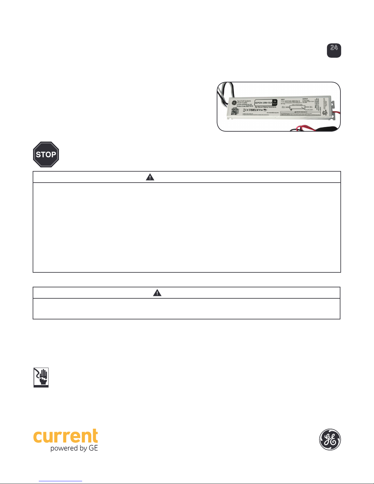
Tetra® LED Systems Power Supply
GEPS24-100U-GLX
Power Supply Features
• Supports Tetra PowerStrip SS, Tetra PowerStrip DS, Tetra miniStrip DS,
Tetra Edgestrip, Tetra Contour, Tetra Contour LS, Tetra miniMAX,
Tetra MS, Tetra MAX, Tetra PowerMAX, Tetra PowerMAX HO and Tetra Stick
LED lighting systems
• UL: Class 2 wiring per NEC Article 725, dry and damp location rated
• IEC: SELV, CE: IP54 rated, must be protected from direct exposure to the weather
BEFORE YOU BEGIN
Read these instructions completely and carefully.
WARNING/AVERTISSEMENT
RISK OF ELECTRIC SHOCK
• Disconnect power at fuse box or circuit breaker before servicing
or installing product.
• Properly ground Tetra® power supply.
• AC input connections shall be suitably enclosed. The power
supply shall be enclosed or made inaccessible to users during
normal use.
RISK OF FIRE
• Minimum power supply spacing to other power supply or other
heat producing component shall be at least 4” (101.6 mm) from
side to side and 1” (25.4mm) from end to end.
• Use only approved wire for input/output connection. Minimum
size 18 AWG (0.82 mm2).
• Follow all local codes.
RISQUES DE DÉCHARGES ÉLECTRIQUES
• Coupez l’alimentation électrique à la boîte de fusibles ou au disjoncteur avant
l’entretien ou l’installation du produit.
• Assurez-vous de correctement mettre à terre l’alimentation électrique Tetra®.
RISQUES D’INCENDIE
• N’utilisez que des ls approuvés pour les entrées/sorties de connexion.
Taille minimum 18 AWG (0.82 mm2).
• Respectez tous les codes locaux.
Installation Guide
24
Volt
RISK OF INJURY
• While performing installations described, gloves, safety glasses
or goggles should be worn.
Save These Instructions
Use only in the manner intended by the manufacturer.
If you have any questions, contact the manufacturer.
Prepare Electrical Wiring
Electrical Requirements
• Limited to use in dry and damp locations.
• The suitability of rain enclosure shall be determined if
intended for wet location.
• The grounding and bonding of the LED Driver shall be
done in accordance with National Electric Code (NEC)
Article 600.
• Follow all National Electric Codes (NEC) and local codes.
CAUTION/ATTENTION
RISQUE DE BLESSURE
• Lors de l’exécution des installations décrites, des gants, des lunettes de
sécurité ou des lunettes de protection doivent être portées.
This device complies with part 15 of the FCC Rules. Operation is subject
to the following two conditions: (1) This device may not cause harmful
interference, and (2) this device must accept any interference received,
including interference that may cause undesired operation.
Note: This equipment has been tested and found to comply with the limits
for a Class A digital device, pursuant to part 15 of the FCC Rules. These
limits are designed to provide reasonable protection against harmful
interference when the equipment is operated in a commercial environment.
This equipment generates, uses, and can radiate radio frequency energy
and, if not installed and used in accordance with the instruction manual,
may cause harmful interference to radio communications. Operation of
this equipment in a residential area is likely to cause harmful interference in
which case the user will be required to correct the interference at his own
expense.
This Class [A] RFLD complies with the Canadian standard ICES-005. Ce DEFR
de la classe [A] est conforme à la NMB-005 du Canada.
1
Power Supply Installation
Input
wires
Red (+)
Black (line)
White (neutral)
AC line
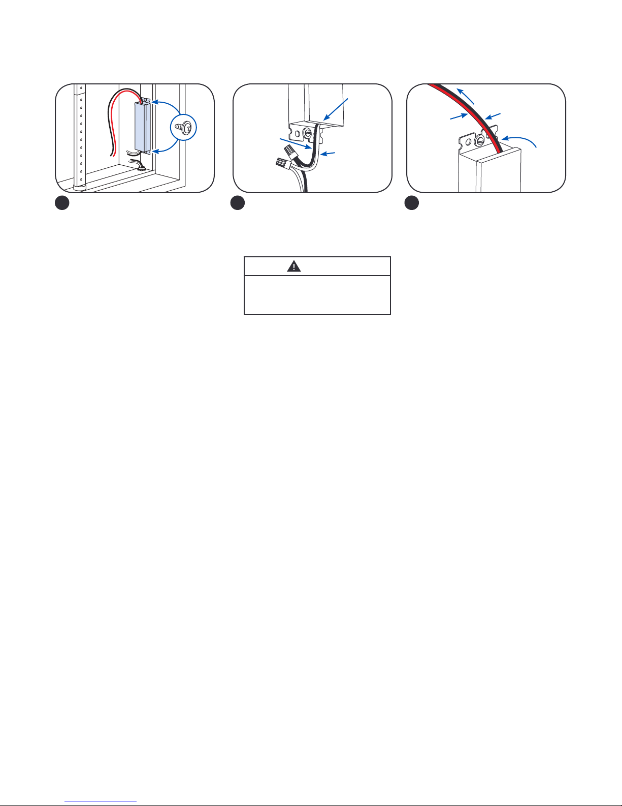
Mount the power supply. Mounting
1
the power supply base directly to
a thermally conductive installation
surface can improve thermal
performance.
NOTE: All electrical connections
should be suitably protected from
mechanical damage and the
environment. Seal all connections
exposed to water with electrical
grade self-hardening silicone.
NOTE: For CSA approval, a disconnect/toggle switch of appropriate rating needs to be placed within 29.5 ft. (9 m) of primary side
of the power supply. The minimum rating of the switch must be either 120 or 220 Volts AC. The switch must also support twice the
amount of input current.
NOTE: When installing power supply, connect to the appropriate sized building breaker or disconnect device for line and neutral
connections, in accordance with local, state or country regulations.
NOTE: The grounding and bonding of the power supply and overall sign shall be done in accordance with National Electric Code
(NEC) Article 600.
Connect the AC line to the black
2
(line) and white (neutral) input
wires of the power supply using
suitable wire connectors.
WARNING
RISK OF ELECTRIC SHOCK
AC input connections shall be
suitably enclosed.
Connect the supply wire that is
3
attached to the Tetra LED System to
the red (+) and black (-) output wires
of the power supply as outlined in
the “Electrical Connections” section
of your LED system’s Installation
Instructions.
To Tetra LED System
Black (-)
Output
wires
Retrot Instructions
1. (Existing Signs Only) Prior to installation, survey the site for information regarding power and accessibility inside and outside the
building. Ensure that the branch circuit supplying the existing transformer or ballast will be within the voltage ratings of the new LED
power supply, and have a current rating not exceeding 20A, or that permitted by applicable local, state, or country electrical codes
(whichever is less).
2. (Existing Signs Only) Remove the existing lighting equipment to be replaced, such as neon tubing or uorescent tubes; and
associated transformers and ballasts. Care should be taken not to break the existing neon or uorescent tubes. NOTE: Follow all
federal and local regulations when disposing of neon tubing, uorescent tubes, transformers and ballasts.
3. (Existing Signs Only) If removal of the existing lighting equipment eliminates the disconnect switch, as required by applicable local,
state, or country electrical codes; a new disconnect switch must be installed.
4. (Existing Signs Only) Make sure the removal of lighting equipment does not compromise the integrity of the sign body (i.e. water
intrusion). Fill in all holes 0.5 in. (13 mm) or smaller with the appropriate amount of rated caulk or sealant. For holes greater than
0.5 in. (13 mm), use an aluminum or zinc coated steel patch with rivets and sealant.
5. Using the layout guidelines within the LED module installation instructions, determine required number of LED modules required to
illuminate the sign.
6. Using the applicable LED module maximum Loading chart, determine the number of Tetra Class 2 Power Supplies required to power
the number of LED modules required to illuminate the sign, so as not to overload any single power supply output.
7. Follow the LED module instructions to properly mount the LED modules.
8. Connect the DC output of the power supply to the LED modules using the Power Supply Installation instructions above.
9. Connect the power unit to the supply in accordance with the applicable local, state, and country electrical codes, and the Power
Supply Installation instructions above.
10. If required, the disconnect switch shall be installed by qualied personnel, in accordance with applicable local, state, and country
electrical codes.
2
 Loading...