

Tetra® 24/24 Module
GESTBR 24/24
24/24 Module Features
• Built to interface between the GEPS24-100U-NA/GEPS24-100U-GL
& GEPS24-180U driver and the GEWHBIP2, GEWHBIP2-50K,
GEWWBIP2-41K, GEWWBIP2, & GEBI56-1 LED modules only.
• UL: Class 2 input.
BEFORE YOU BEGIN
Read these instructions completely and carefully.
WARNING/AVERTISSEMENT
RISK OF ELECTRIC SHOCK
∙ Turn power off before inspection, installation or
removal.
∙ Properly ground GE power supply enclosure.
RISK OF FIRE
∙ Use only UL approved wire for input/output
connections. Minimum size 18 AWG (0.82mm2)
∙ Follow all NEC and local codes.
∙ Not to be submerged or used in a marine environment.
RISK OF FIRE OR ELECTRIC SHOCK
∙ LED Retrot Kit installation requires knowledge of sign
electrical systems. If not qualied, do not attempt
installation. Contact a qualied electrician.
∙ Install this kit only in host signs that have been identied
in the installation instructions and where the input rating
of the retrot kit does not exceed the input rating of the
sign.
∙ Installation of this LED retrot kit may involve drilling or
punching of holes into the structure of the sign. Check
for enclosed wiring and components to avoid damage
to wiring and electrical parts.
∙ Do not make or alter any open holes in an enclosure of
wiring or electrical components during kit installation.
RISQUES DE DÉCHARGES ÉLECTRIQUES
∙ Coupez l’alimentation avant l’inspection, l’installation ou le déplacement.
∙ Assurez-vous de correctement mettre à terre l’alimentation électrique GE.
RISQUES D’INCENDIE
∙ N’utilisez que des ls approuvés par UL pour les entrées/sorties de connexion.
Taille minimum 18 AWG (0.82mm2)
∙ Respectez tous les codes NEC et codes locaux.
∙ Ne pas submerger ou installer dans un environnement marin.
RISQUE D’INCENDIE OU DE CHOC ÉLECTRIQUE
∙ L’installation de l’équipement de remplacement DEL exige Ia connaissance des
systèmes électriques pour enseignes. Si non qualié, ne tentez pas d’installation.
Veuillez contacter un électricien qualié.
∙ Risque d’incendie ou de choc Électrique. Installez cet ensemble seulement dans
des enseignes hôtes qui ont été identiés dans les instructions d’installation et
dont la capacité d’entrée de l’ensemble ne dépasse pas la capacité d’entrée de
l’enseigne.
∙ L’installation de cet équipement de remplacement DEL peut impliquer le perçage
ou le poinçonnage de trous dans la structure du panneau Vériez le câblage et
les composants inclus pour éviter d’endommager le câblage et les composants
électriques.
∙ Ne pas faire ou modier les trous ouverts dans une enceinte de câblage
ou de composants électriques pendant l’installation de cet équipement de
remplacement DEL.
Installation Guide
24
Volt
RISK OF INJURY
• While performing installations described, gloves,
safety glasses or goggles should be worn.
Prepare Electrical Wiring
Electrical Requirements
• Acceptable for use in dry, damp and wet locations.
• The grounding and bonding of the LED Driver shall be done in
accordance with National Electric Code (NEC) Article 600.
• Follow all National Electric Codes (NEC) and local codes.
• These products are only suitable for connection to a circuit
from a Class 2 power source.
• These products have not been evaluated for use when connected to a
power source that does not comply with Class 2 voltage and energy
limited supplies.
CAUTION/ATTENTION
RISQUE DE BLESSURE
• Lors de l’exécution des installations décrites, des gants, des lunettes de
sécurité ou des lunettes de protection doivent être portées.
Save These Instructions
Use only in the manner intended by the manufacturer.
If you have any questions, contact the manufacturer.
RETROFIT SIGN CONVERSION LED KIT FOR USE ONLY IN
ACCORDANCE WITH KIT INSTRUCTIONS.
KIT IS COMPLETE ONLY WHEN ALL PARTS REQUIRED BY
THE INSTRUCTIONS ARE PRESENT.
TROUSSE DE CONVERSION À DEL POUR LA
MODERNISATION DES ENSEIGNES
À UTILISER CONFORMÉMENT AU GUIDE D’INSTALLATION.
1
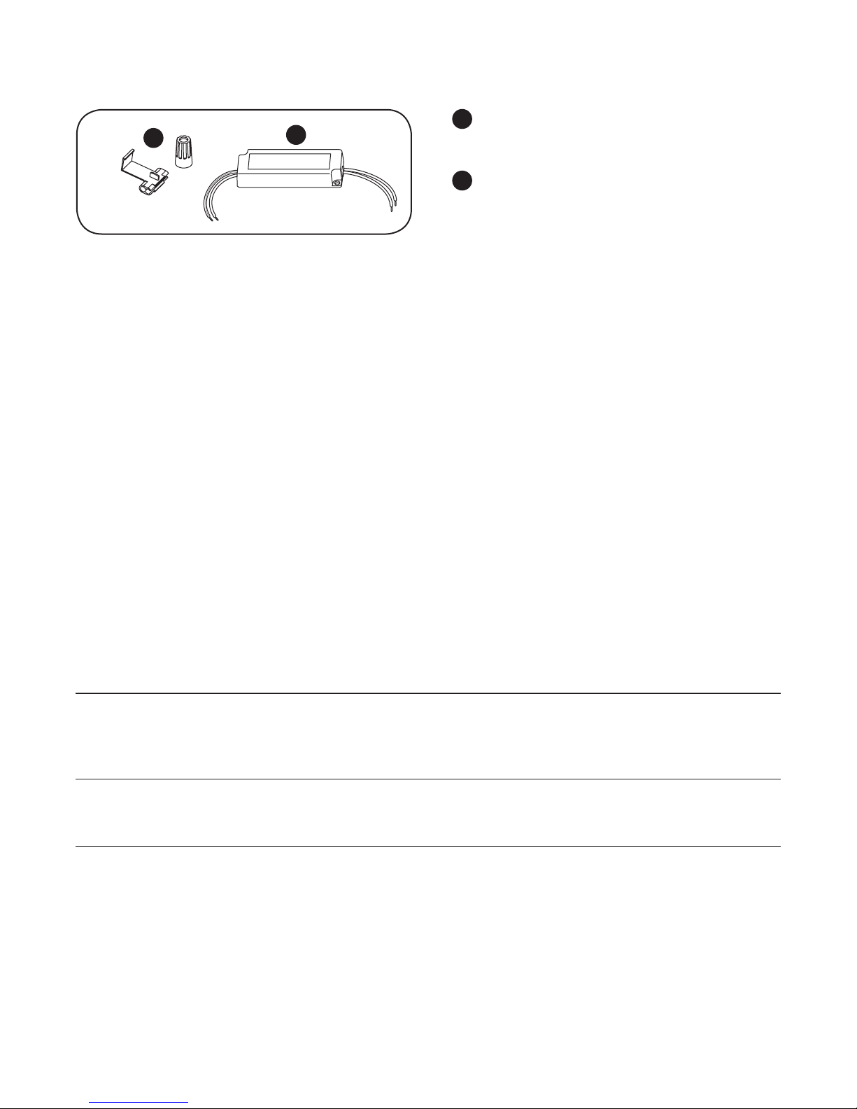
Components
UL certied 22-14 AWG (0.33-2.08 mm2) wire
1
1
2
connectors or 22-18 AWG (0.33-0.82 mm2)
inline/IDC connectors.
Tetra® 24/24 Module.
2
Preparation
If installing a new power supply: Prior to installation, survey the site for information regarding power and accessibility
inside and outside the building. Ensure that the branch circuit supplying the existing LED power supply will be within
the voltage ratings of the new LED power supply, and have a current rating not exceeding 20A, or that permitted by
applicable local, state, or country electrical codes (whichever is less).
If removal of the existing lighting equipment eliminates the disconnect switch, as required by applicable local, state, or
country electrical codes; a new disconnect switch must be installed. If required, the disconnect switch shall be installed
by qualied personnel, in accordance with applicable local, state, and country electrical codes.
Repair and seal any unused openings in the electrical enclosure. Openings greater than 12.7-mm (1/2-in) diameter
require a metal patch secured by screws or rivets and caulked with non-hardening caulk. Smaller openings may be
sealed with non-hardening caulk.
Using the layout guidelines within the LED module installation instructions, determine required number of LED modules
required to illuminate the sign.
The 24/24 Module must be supplied by an output of a Tetra® 24VDC Class 2 Power Supply as listed below. Using the
Maximum Loading chart below, determine the number of Tetra® Class 2 Power Supplies required to power the number of
LED modules required to illuminate the sign, so as not to overload the Tetra® Class 2 Power Supply chosen.
Specications
Maximum Loading per Tetra® 24/24 Module
When used with a
When used with a
24V/100W Power Supply
Note: Load shall not
SKU Rating
GEWHBIP2, GEWHBIP2-50K,
GEWWBIP2-41K, GEWWBIP2
GEBI56-1
Follow the LED module instructions to properly mount the LED modules.
Exceeding the maximum recommended loading above may put the power supply in protection mode
24VDC, 2.40W per module 32 modules/37 ft. (11.28 m)
exceed 4.0A
24V/180W Power Supply
Note: Load shall not exceed
3.8A per 24/24 module on
each (of 2) output channels
32 modules/33 ft. (10.06 m)
per output channel
2
 Loading...