

GE
Measurement & Control
The T8041 and T8042 are CO2
transmitters designed to be
installed in HVAC return air
ducts. The technology is based
on the absorption of light in a
gold-plated reflective light pipe
or waveguide diffusion gas
chamber. A gas permeable
PTFE filter prevents particulate
and water contamination of the
sensor. Light is absorbed in
proportion to the CO
concentration and the
remaining light is measured and converted into an analog signal.
Installation Instructions
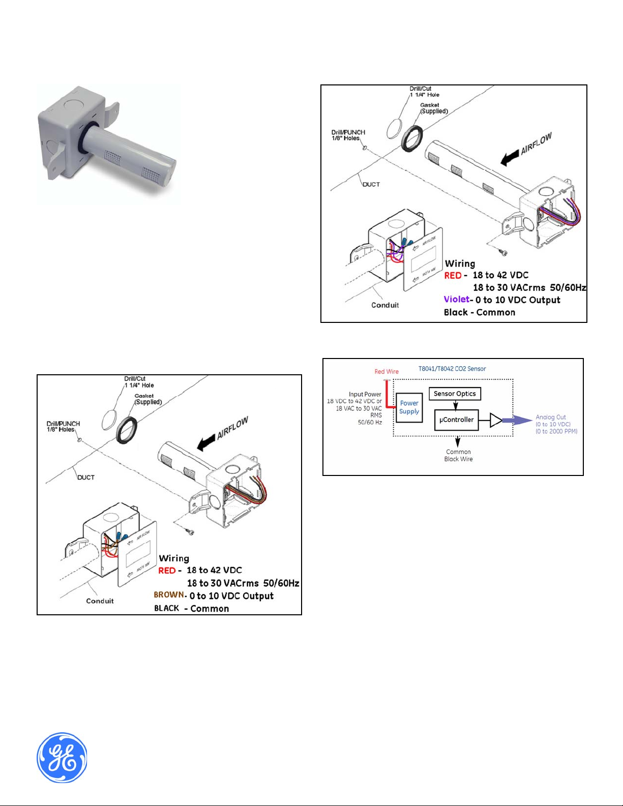
1. Before installing the sensor, note the direction of the airflow. Ensure
all mounting holes are sealed tightly.
2. Drill/cut one 1-1/2” hole and punch/drill two 1/8” holes for
mounting screws.
3. Slide the sensor into 1 ½” hole and secure with #10 sheet metal
screws.
4. Connect the condui t and make necessary wire connections.
5. Install lid, and ensure it snaps into place.
2
Telaire Ventostat™ T8041/T8042
CO
Duct Mount Sensors
2
User Instructions
Figure 2: T8042 Installation
Figure 1: T8041 Installation
Figure 3: Wiring
T63103-005
October 2013
Page 1 of 2

Specifications
Measurement Range
0-2000 PPM fact ory calibrated
Operating Conditions
• Temperature: 0ºC to 50ºC (32ºF to 122ºF)
• Humidity: 0 to 95% relative humidity, non-condensing
Duct Air Velocity
0 to 1500 ft/min (0 to 450 meter/min)
Temperature Dependence
0.2% of full scale per ºC
Stability
<2% of full scale over the life of th e sensor (10 years typical)
*Accuracy
±40 ppm +3% of reading @ 22ºC (72ºF) when compared with a factory
certified reference
Non-linearity
<1% of full scale @ 22ºC (72ºF)
Pressure Dependence
0.13% of reading per mm of mercury
*Calibration
Sensors will be calibrated at zero and span at the factory. Calibration in
the field will not be required. Sensors will be shipped with ABC Lo gic™
turned on.
Storage Conditions
-40ºC to 70ºC (-40ºF to 158ºF)
Output
Voltage 0 to 10 VDC; 0 to 2000 ppm CO2 (100 ohm output impedance)
Power Supply Requirements
18 to 30 VAC RMS, 50/60 Hz or 18 to 42 VDC, polarity protected.
Power Consumption
Typical values (1.65 watts peak, 0.65 watts avg.@ 42 VDC)
*Note: The Telaire product line offers patented ABC Logic™ software
for self correction of drift to better than ±20 pp m per y e ar. The system is
virtually free of maintenance and typically has a lifetime of more than 10
years.
Physical Requirements
Dimensions:
Probe Length: T8041 4.09 in (10.38 cm)
T8042 8.07 in (20.51 cm)
Probe Diameter: 1.24 in (3.15 cm)
Junction Box Depth: 1.58 in (4.02 cm)
Junction Box H x L: 3.05 in x 3.05 in (7.46 cm x 7.46 cm)
Color: Grey (GY6275)
Installation Kit
Response Time
Three minutes typical for a 90% step change at low duct speeds
Included with the transducer are wi re nuts, mounting screws and
installation instructions.
Sampling Rate
Every two seconds
Warm-up Time
< two minutes (operational) ; 1 0 minutes to achieve maximum accuracy
Certifications
RoHS compliance
FCC Part 15,B
CE EMC EN61000-6-2, class B, criterion B*
*Deviations of the output signal may occur during strong electrical fast
transients on the power line
Enclosure flammability rating – UL94-5VA
Page 2 Telaire Ventostat™ T8041/T8042 Series
 Loading...