

GE
H
FLOW
L
Filter must be
attached to the
“H” side of the
pitot tube
Sensing
Telaire Ventostat® 8000 Series CO2 Sensors
User Instructions
Introduction
The GE Telaire Ventostat® 8001/
8002 carbon dioxide (CO
controllers are designed for Demand
Controlled Ventilation (DCV) in
buildings. This approach, using CO2 as
an indicator of occupancy, allows
ventilation based on actual occupancy
while still maintaining ASHARE
recommended per-person ventilation
rates. Over ventilation of buildings can
be reduced, energy can be saved, and
quality can be optimized.
The optional black case (PN 8001B and
PN 8002B) is UL94-V5 rated, making
these models suitable for mounting
directly inside the ductwork. Typical
applications for Ventostat
conference rooms, schools, retail stores, restaurants, gymnasiums, and
movie theatres.
) sensors and
2
®
8001/8002 series include office buildings,
Installing the Sensor
NOTICE!
Use of cellular telephones or radio transceivers within two (2) feet of the
sensor during calibration process could cause sensor interference,
calibration errors and affect sensor accuracy. Please refrain from using
these devices during sensor calibration.
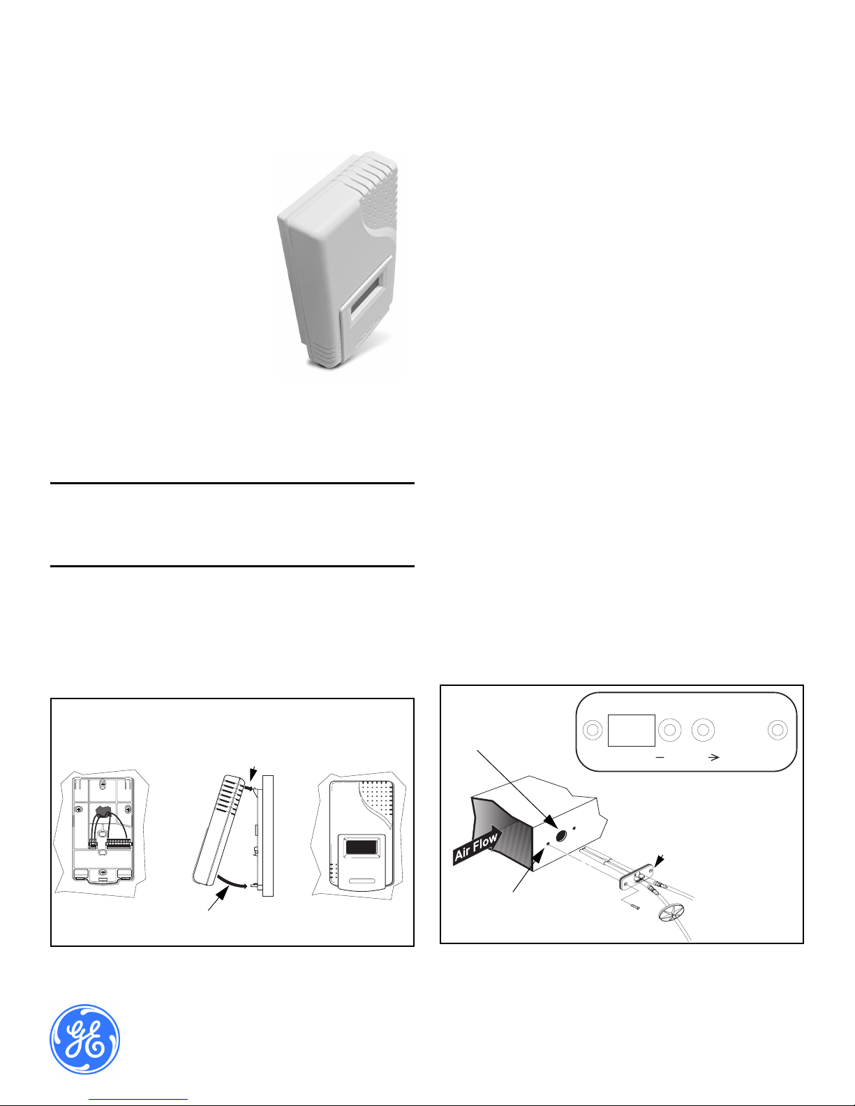
Install the mounting plate and sensor as follows:
1. Prepare for installation by using the mounting holes configured for
US or European junction boxes.
2. Use the mounting plate as a template to mark the mounting holes.
See Figure 1, View A below.
3. Secure the mounting plate to the wall or junction box and make
necessary wire connections.
4. Mount the controller on the base by aligning the top clips and then
securing to the bottom clips, as shown in Figure 1, View B above. A
“snap” sound will indicate that the sensor is secure. The sensor will
now have power. A 2 minute warm-up will take place. After 2
minutes, the sensor will stabilize and display the “Normal Mode”
(current CO
5. At this point one of nine preset programs or one custom channel can
be selected for operation. See the section “Configuring the Sensor”
on page 3.
6. Finish installation by sliding the cover over the menu keys and
secure with the supplied screw.
readings).
2
Mounting the Sensor into the Duct
The 8001B and 8002B have the UL94-V5 rated black case and are
specifically designed for mounting inside the return air ductwork. When
mounting these products inside the ductwork, seal the hole around the
wires and leave the duct insulation in place to prevent condensation
which may damage the sensor.
Pitot Tube Installation for the
8001 and 8002
Install the mounting bracket, then install the pitot tube assembly as
follows:
Note: The length of the Tygon
maintain optimum accuracy, the tubing should not be
lengthened. If the sensor is mounted closer than three
feet, the excess tubing should be shortened to avoid
interference with mechanical or moving devices.
1. To mount the pitot tube, drill one 7/8” hole through the duct as
shown in Figure 2 below.
®
tubing is three feet. In order to
Mounting
Plate
Bottom Clips
View A View B View C
Ventostat
CO
Controller
Top Clips
2
Figure 1: Ventostat® CO2 Controller - Mounting
Sensor/
Drill One Hole
7/8” in Diameter
View in Direction of A
Mounting
Flange
clear
mode
enter
Drill Two Machine
Screw Holes
Figure 2: Pitot Tube - Installation
T62659-007
October 2006
Page 1 of 7
2. Insert the pitot tube and mark the two remaining holes for the
mounting screws.
3. Punch or drill the two marked holes.
4. Note the direction of airflow in the duct (see View in Direction of A)
above.
5. Note the marking on the pitot tube flange and insert the tube so that
it is properly aligned with the airflow.
6. To ensure an airtight seal, make sure the mounting surface of the
duct is clear of dirt or obstructions. Then, attach the pitot tube to the
duct with sheet metal screws or rivets.
7. On top of the sensor, unscrew the protective caps from the tube
connectors.
8. Check the length of the tubing before attaching to the sensor. The
tubing should connect without stretching or pulling. If the length is
long enough to create a loop or bind in the tubing, it should be
shortened.
9. To shorten the tubing, remove the connectors that attach to the
sensor and cut the tubing to the required length.
10. Replace the tubing connectors by using a twisting or screwing
motion.Verify the connection is secure.
Note: If the tubing length has been shortened, be sure the in-
line filter is replaced on the pitot tube connector marked
with an “H” as shown in Figure 2, View in Direction of
A (on the previous page).
11. Complete the installation by screwing the tube connectors to the
input ports on the sensor. The tubing connectors can be attached to
either input port. It will not affect the performance of the sensor.
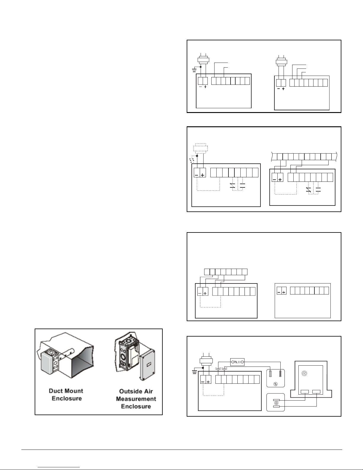
Accessory Enclosures
Three kinds of accessory enclosures are listed below, and two are shown
in Figure 3 below.
• Model 1508 Duct Mount Enclosure (Aspiration Box) - Any 8000
product can be installed inside this enclosure.
• Model 1551 Outside Air Measurement Enclosure - This NEMA-
3R enclosure is weatherproof for measuring outside air CO2 con-
centrations. It also includes heat stabilizers.
• Model 1505 Harsh Environment Enclosure - For extreme envi-
ronments where the sensor might be subjected to condensation or
water spray such as those found in greenhouses or breweriesNEMA-3R rated.
The typical wiring diagrams appear in Figure 4 through Figure 8
below.
AC Power 3-Wire System
L1
L2
18-30 VAC RMS
Use Either Output
0-10Vout
4-20mAout
1
2
Input
MountingBracket
78
6
Ventostat
5
®
Isolated AC Power 4-Wire System
L1
L2
18-30 VAC RMS
1234
1
2
Input
Ventostat
MountingBracket
5
78
6
0-10Vout
SignalGround
4-20mAout
®
1234
Figure 4: AC Power 3/4 Wires System - Diagrams
Using the Relay Contacts
18-30 VAC RMS
L1
L2
5
7
6
8
1
2
Input
Common
Ventostat
Mounting Bracket
3
4
NC NO
COM
®
Lennox L-Series
TB1
12
2
Ventostat MountingBracket
+
24VAC
6
7
1
Input
Common
24VAC
GND
8
8
AC In
Common
24V
9
10
11 121314
7
6
NC NO
5
4
COM
+10VDCIn
16
15
3
12
Figure 5: Relay Contacts and Lennox L-Series
Diagrams
Lennox L-Series w/Johnson Controls
Metasys UNT or Facilitator FA-UNT
+
AC
24V
GND
24VAC
AI-CM
5
4
6
8
7
7
8
1
2
Input
Common
6
Ventostat MountingBracket
AI-3
3
2
TB1
1
5
3
12
4
8-Pin and 2-Pin Terminal
Block Pin Designations on
the Ventostat Mounting Bracket
AC- / GND
AC+ / DC+
0-10V Output
Signal Ground
4-20mA Output
Relay Norm Closed
Relay Common
Relay Norm Open
Not Used
Not Used
5
78
1
2
Input
Ventostat
Mounting Bracket
6
1234
®
Figure 6: Lennox L-Series/Mounting Bracket Diagrams
Figure 3: Accessory Enclosures
Typical Wiring Diagrams
Page 2 Telaire Ventostat™ 8000 Series
Honeywell M7415 Damper Actuator with W7459 Logic Module
(+)
Honeywell Damper
Actuator M7415 and
W7459 Logic Module
PP1
18-30 VAC RMS
L1
L2
1
2
Input
Common
OptionalHigh
and/or Low
Temp Swtich
5
78
6
Ventostat MountingBracket
Honeywell
Q769C 0-10 Vdc
Adaptor
Black
White
3
1
4
2
(-)
Front View
(P1)
(P)
Rear View
Figure 7: Damper Actuator and W7459 Logic Module
Diagrams
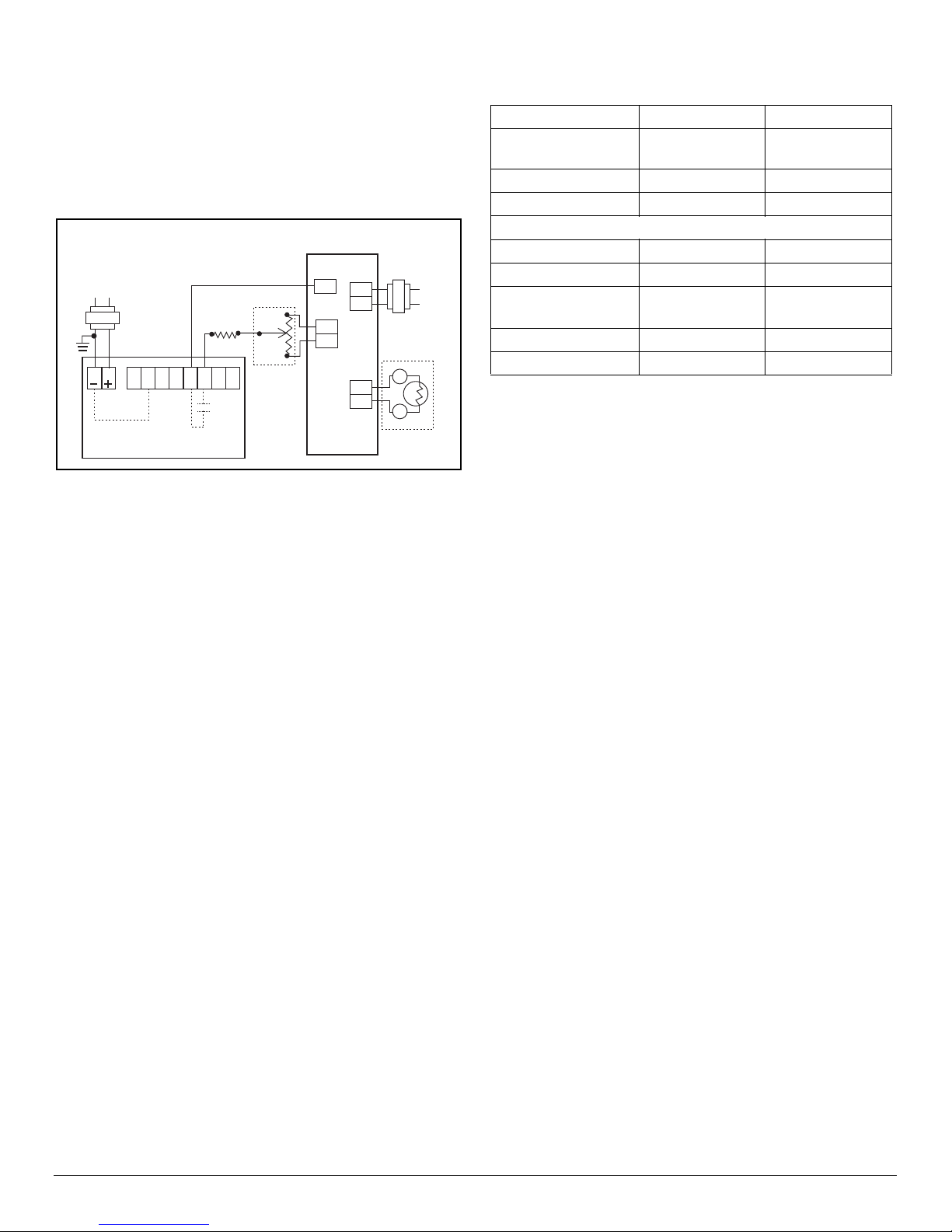
Set minimum position potentiometer to twice the design load. For
example, if the space is designed for 30 people at 15 cfm/person, adjust
the minimum position potentiometer at the economizer logic to 900 cfm.
This will allow the economizer to introduce 450 cfm (1000 ppm CO
level) at the design load. The CO
sensor should use “STDSET#1.”
2
2
Note: For 24V, do not use a HVAC unit transformer. Provide
24 V by using a non-grounding transformer.
Johnson Controls M100E Economizer Actuator with R81EAA-2
Interface Board
L1
L2
1
2
Input
Common
Ventostat MountingBracket
Y45AA-9 Remote Minimum
Position Potentiometer
(1,000-10,000 ohm)
5
78
6
3
4
Common
M100E
8
T2
Open
Close
12
T1
9
10
S2
S1
L1
L2
A91Mixed Air
Thermistor
B
T
R
Figure 8: Economizer Actuator and Interface Board -
Diagrams
Table 1: 8000 Series Adjustment Parameters and
Factory Settings
Adjustment Range Factory Setting
Altitude Above Sea
Level
ABC Logic™ ON/OFF ON
Select Standard Setting 1 to 9 1
Customize Setting:
PPM Range 0 - 10,000 0-2,000
Output Range 4-20 mA/ 0 - 10 V 4 - 20 mA/ 0-10 V
Proportional/
Exponential Output
Relay Setpoint 0 - 10,000 PPM 1000 PPM
Relay Hysteresis 0 - 10,000 PPM 50 PPM
All GE Telaire 8000 series products are calibrated at sea level. As
altitude increases, the accuracy of this sensor, as of all gas sensors,
introduces an error of approximately -3% of the reading per 1,000 ft of
elevation. Users that are in elevations significantly higher than sea level,
such as Denver, Colorado, should consider adjusting the altitude to have
the most accurate reading. The altitude setting can be adjusted on the
unit in 500 ft increments.
0 - 10,000 ft. 0 ft.
Select One Proportional
Configuring the Sensor
The sensor has two different settings:
• User Adjustable Sensor Settings
• Factory Settings
User Adjustable Sensor Settings
The GE Telaire 8000 series includes features which are user adjustable.
These adjustments can be made using the keypad on display units, or by
the PC based UIP program that communicates to the sensor via a custom
RS232 interface cable.
Factory Settings
The default settings are the typical settings used by a building control
system.
If the installation requires changes to the sensor, the user can customize
certain characteristics of the sensor. For example, non-factory settings
may be applicable when the sensor is being connected to equipment that
has a fixed input range (e.g., actuators used with economizer systems).
Sensor Programming Features
Outlined below in Table 1 are the adjustable parameters of the sensor
and the factory setting. In addition to offering these adjustable features,
the programming interface allows for a fast and simple adjustment of
sensor calibration.
ABC Logic™ Self Calibration System
All GE Telaire 8000 series sensors are factory set with the ABC Logic
(Automatic Background Calibration) self calibration feature ON. This
feature allows the sensor to continually re-calibrate itself when the
indoor concentrations drop to outside levels while the building is
unoccupied. Generally a building must be regularly unoccupied for 4
hours or more for this self-calibration system to operate properly. Under
these conditions, the ABC Logic feature should maintain sensor
calibration over the lifetime of the sensor. The ABC Logic feature should
be turned OFF where a building is continuously occupied 24 hours per
day, or where there could be significant sources of non-occupant related
CO
such as greenhouses, breweries and other industrial and food
2
processing applications.
Pre-Programmed Settings
In addition to the factory setting for the 8000 series sensors, nine
standard settings can easily be selected using the keypad (display units
only) or the PC based UIP Program. Table 2 on the next page describes
each of the settings. The definitions for some of the terms used in the
table are described in more detail as part of the custom settings outline in
the “Custom Settings” section on the next page.
Settings 1, 2 and 3 are applicable for automated or computerized
building control systems.
Settings 4 to 7 are specifically designed for operation with economizer
controls and actuators where a 0-10 VDC signal will provide 0-100%
outside air modulation. These control settings provide different
modulation ranges, depending on the target cfm-per-person ventilation
rate desired. As described below, the exponential setting is best used in
applications that have large volumes of air and people, such as
auditoriums, gyms and large conference areas.
Telaire Ventostat™ 8000 Series Page 3
Setting 8 is for use in occupational health and safety applications where
users want to measure concentrations in relation to the 5000 ppm, 8 hour
exposure levels established by OSHA (Occupation Safety and Health
Administration).
 Loading...