

GE Telaire Ventostat 8000 Series User Instructions
Telaire Ventostat™ 8000 Series
CO
2
Sensor
User Instructions
GE
Measurement & Control
T63216-006
January 2012
Page 1 of 4
Installing the Sensor
!WARNING!
Before performing service or maintenance operations on
the systems, turn OFF main power switches to the unit.
Electric shock can cause personal injury. Please read and
follow the wiring instructions precisely; miswiring may
cause permanent damage to the product.
Basic Installation for Non-Display Units
1. Separate the case into its front and rear sections.
2. Secure the rear section of the case to the wall or junction box using
the supplied screws, and make necessary wire connections.
3. Mount the Controller on the base by aligning the top clips and then
securing to the bottom clips. Secure the Ventostat with the supplied
set screw. A one-minute stabilization warmup will take place.
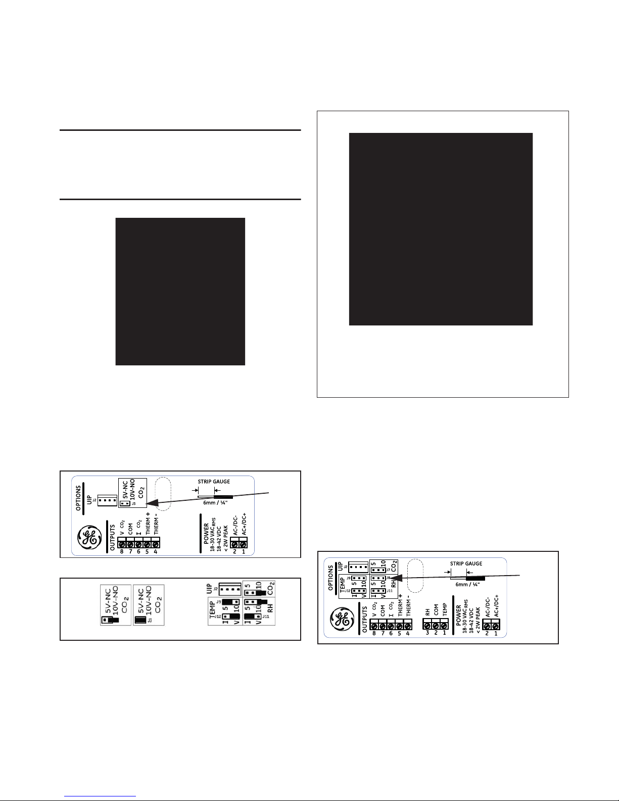
Internal Label for Non-Display Units
Jumper Settings for Non-Display (a) and Display (b)
Units
Note: Example b shows outputs of CO2 — 4-20 mA and CO2 — 0-10
V, humidity— 4-20 mA, and active temperature — 0-5 V.
GE Measurement & Control
6860 Cortona Dr., Suite B
Goleta, CA 93117
www.ge-mcs.com
Basic Installation for Display Units
1. Separate the case into its front and rear sections.
2. Secure the rear section of the case to the wall or junction box using
the supplied screws, and make necessary wire connections.
3. Mount the Controller on the base by aligning the top clips and then
securing to the bottom clips. Secure the Ventostat with the supplied
set screw. A one-minute stabilization warmup will take place.
4. When fitting the T8300 (pitot tube version), complete the
installation by screwing the tube connectors to the input ports on the
sensor. The tubing connectors can be attached to either input port. It
will not affect the performance of the sensor. (See page 3 for further
instructions.)
Internal Label for Display Units
Output
Jumper
Selections
(a)
(b)
0-10V
0-5 V
Output
Jumper
Selections
Page 2 Telaire Ventostat™ 8000 Series
Ventostat Wiring Diagrams
The Ventostat family of products has two basic configurations. One
configuration provides three active outputs (CO
2
, RH and temperature)
and an independent thermistor. It has an output terminal block with pins
#1, 2 and 3. The other configuration provides only CO
2
outputs and an
independent thermistor and has no terminal block with pins 1, 2, and 3
installed. For electrical wiring and power supply requirements, these two
configurations are identical; please follow the specific instructions for
wiring. The recommended wire gauge is 18-22 AWG (1.0 to 0.75
metric).
!WARNING!
Ventostat products have three terminal pins that are
connected inside the sensor to a common/ground: pin
#2, 5 and 7 on the I/O terminal blocks and pin #2 on the
power block. Do NOT connect positive (hot) 24 VAC power
line to terminal number 2 of the terminal block.
Caution!
The T8100 Ventostats are either 3-wire or 4-wire type
configurations, powered by either AC or DC voltage. They
are not 2-wire or loop-powered devices. Wiring the units as
2-wire or loop-powered devices will irreparably damage the
sensors and void the warranty.
Note: For temperature measurements, Ventostat models contain a
passive thermistor (terminal pins #4 and 5), which is
electrically isolated from the other circuitry and should be
wired independently from active CO2/RH/temperature outputs.
The thermistor has no connection to the Ventostat common
ground and/or power.
The active temperature output has the same common (ground)
as CO
2
and RH outputs.
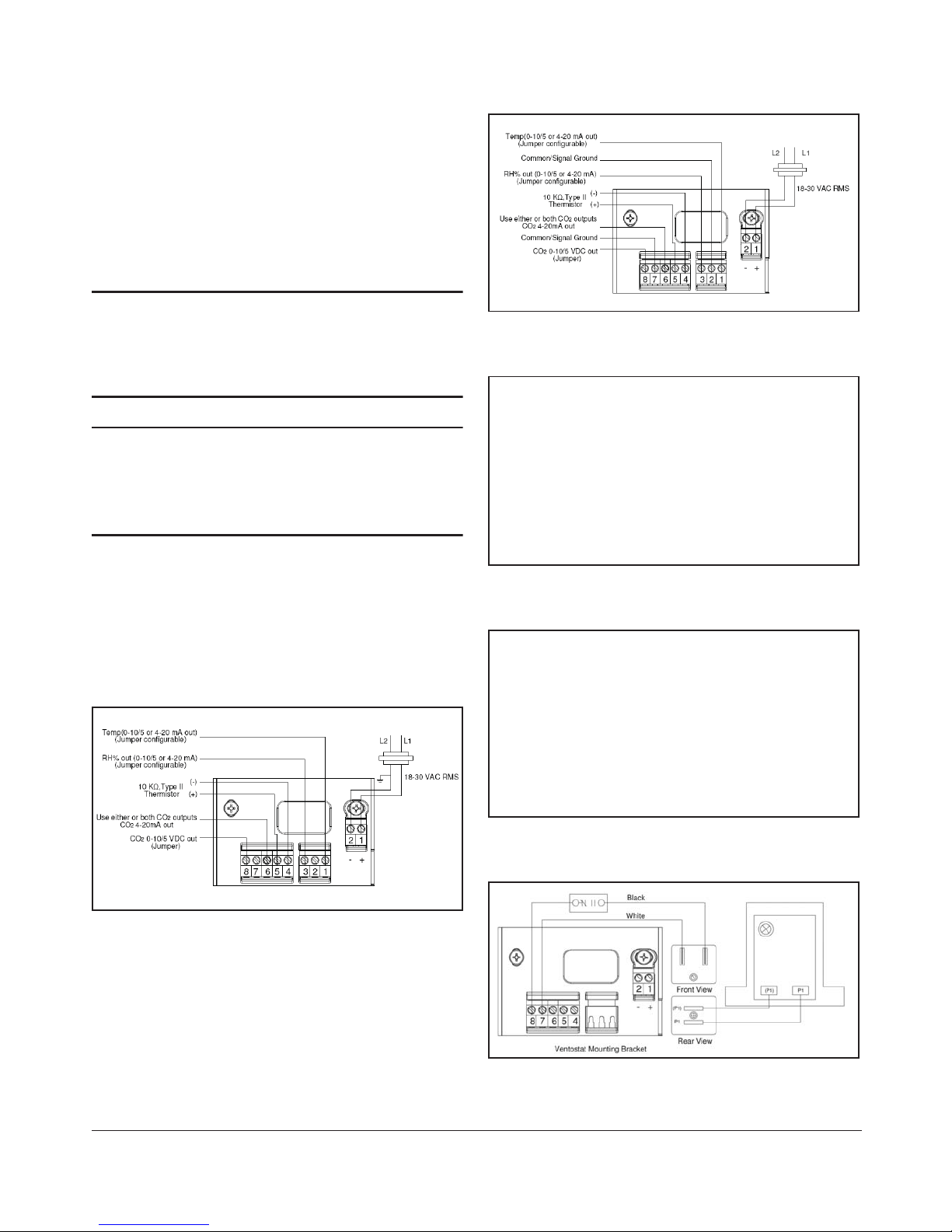
Figure 1: Display Unit Wiring for 3-Wire System, AC
Power
Figure 2: Display Unit Wiring for 4-Wire System, AC
Power
Figure 3: Non-Display Unit Wiring for 3-Wire System,
AC Power
Figure 4: Non-Display Unit Wiring for 4-Wire System,
AC Power
Figure 5: Wiring CO
2
Sensor Voltage Output to
Honeywell M7415 Damper Actuator with W7459 Logic
Module
 Loading...