

GE TBQ440ANDR, TBQ470ANDR, TBR427ANDR, TBG470ANDR, TBR463ANDR Technician Service Manual
...
g GE Appliances Service Training
____________________________
TECHNICIAN
SERVICE MANUAL
Refrigerator
MODELS:
TBG440ANDR TBQ440ANDR TBR427ANDR
TBG470ANDR TBQ470ANDR TBR463ANDR
TBG530ANDR TBQ530ANDR TBR527ANDR
TBG570ANDR TBQ570ANDR TBR565ANDR
TMG432ANDR
TMQ432ANDR
TMR432ANDR
PUB NO. : SPWR1020E
November 2001 - Revised (3)

IMPORTANT SAFETY NOTICE
The information in this service guide is intended for use by
individuals possessing adequate backgrounds of electrical,
electronic and mechanical experience. Any attempt to repair
a major appliance may result in personal injury and property
damage. The manufacturer or seller cannot be responsible
for the interpretation of this information, nor can it assume any
liability in connection with its use.
WARNING
To avoid personal injury, disconnect power before servicing
this product. If electrical power is required for diagnosis or
test purposes, disconnect the power immediately after performing the necessary checks.
RECONNECT ALL GROUNDING DEVICES
If grounding wires, screws, straps, clips, nuts, or washers used
to complete a path to ground are removed for service, they
must be returned to their original position and properly fastened.
Page 2
THE MANUAL COVERS THE
FOLLOWING MODELS
MODEL # COUNTRY
TBR427ANDR
TBR463ANDR
TBR527ANDR
TBR565ANDR
TMR432ANDR
N/A BANGLADESH
N/A CHINA
TBQ440ANDR
TBQ470ANDR
TBQ530ANDR
TBQ570ANDR
AUSTRALIA
HONG KONG
TMQ432ANDR
N/A INDIA
TMG432ANDR INDONESIA
N/A JAPAN
N/A KOREA
N/A MALAYSIA
N/A PAKISTAN
N/A PHILIPPINES
Page 3

THE MANUAL COVERS THE
FOLLOWING MODELS
MODEL # COUNTRY
TBQ440ANDR
TBQ470ANDR
TBQ530ANDR
TBQ570ANDR
TMQ432ANDR
N/A TAIHITI
N/A TAIWAN
TBG440ANDR
TBG470ANDR
TBG530ANDR
TBG570ANDR
SINGAPORE
THAILAND
TMG432ANDR
TMG432ANDR VIETNAM
Page 4

I. SAFETY PRECAUTIONS
PLEASE READ THE FOLLOWINGS BEFORE SERVICING YOUR REGRIGERATOR.
1. Check if an electric leakage occurs in the set.
2. To prevent electric shock, unplug prior to servicing.
3. In case of testing with power on, wear rubber gloves to prevent electric shock.
4. If you use any appliances, check regular current, voltage and capacity.
5. Dont touch metal products in cold freezer with wet hand. It may cause frostbite.
6. Prevent water flowing to electric elements in mechanical parts.
7. When you stand up during observing the lower part with the upper door open, move with care to prevent head would
which may happen by hitting the upper door.
8. When sloping the set, remove any materials on the set, especially thin plate type. (ex.: glass shelf or books.)
9. When servicing evaporator part, wear cotton gloves without fail. It is to prevent wound by sharp fin of evaporator.
10. Leave a breakage of refrigerating cycle to a heavy service center. The gas in cycle inside may soil ambient air.
Page 5
TBR / TBQ / TBG 570 ANDR
TBR / TBQ / TBG 530 ANDR
TBR / TBQ / TBG 470 ANDR
TBR / TBQ / TBG 440 ANDR
TMG / TMR / TMQ432 ANDR
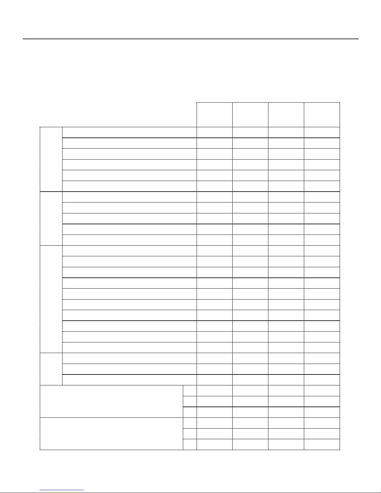
Refrigerant R-134a R-134a R-134a R-134a
Capacities (Liter) 560 500 450 410
Capacities (Cu. Feet) 19.8 17.7 15.9 14.5
Fan cooling ****
Exterior
New Round Face & Arc Design ****
Recessed Handle ****
Automatic Defrosting System ****
Interior Lamp
II. SPECIFICATIONS
565 / 570
ANDR
527 / 530
ANDR
463 / 470
ANDR
427 / 440
/ 432
ANDR
Transparent Plastic Shelf ****
Freezer
Twisted Ice Tray ****
Transparent Door Racks ****
Deodorizing Device ****
Multi Air Flow ****
Temperature Controlled Meat Keeper ****
Transparent Shelf with Steel Frame ****
Large Interior Lamp ****
Vegetable Crisper with Moisture Control * *
Refrigerator
Traditional Vegetable Crisper * *
Transparent Door Racks ****
Large Bottle / Beer Storage Rack ****
Egg Storage Bucket ****
Silver Gray ****
Navy Blue * *
Color
Wine Red ****
Net Dimension (mm)
W 754 754 674 674
Packing Dimension (mm)
H 1803 1701 1776 1676
D 690 690 660 660
W 824 824 744 744
H 1881 1779 1844 1744
D 780 780 780 780
Page 6
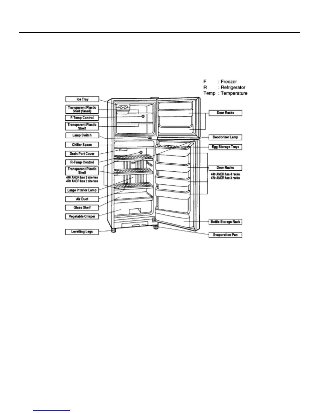
TBG440ANDR / TBG470ANDR
TBQ440ANDR / TBQ470ANDR
TBR427ANDR / TBR463ANDR
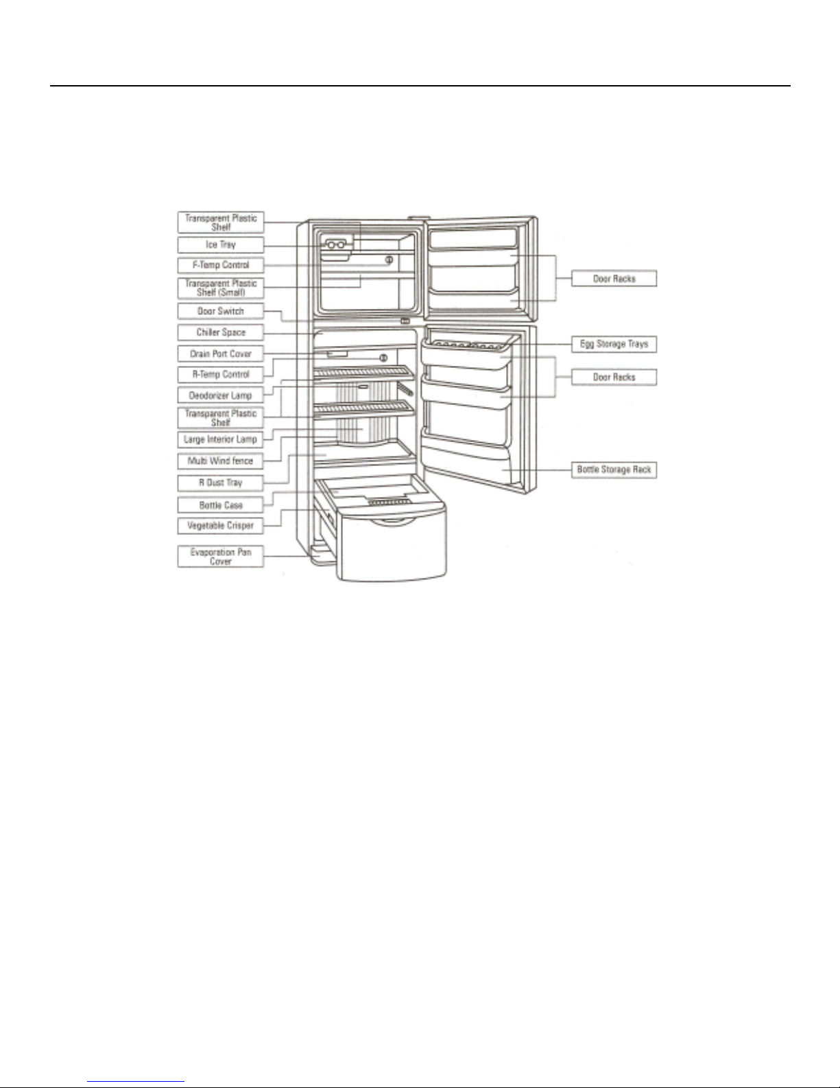
III. PARTS IDENTIFICATION
Note : Because of ice expansion, containers with water may deform in the freezer.
3.1 FEATURES
Ice Tray : Can make and store 1 kg of ice cube.
Temp Controlled Meat Keeper : The fish and meats which will be cooked within 2 days can store here, no
Evaporation Pan : Water discharged from the refrigerator is evaporated here.
Door Racks (F) : Short-term storage of frozen food.
Egg Storage Basket : Can store 16 eggs
Door Racks (R) : Short-term storage of refrigerated food.
Bottle Storage Rack : Can store 5 bottles of beer or soda.
Regulator : For regulation of the refrigerator.
thawing is required.
Page 7
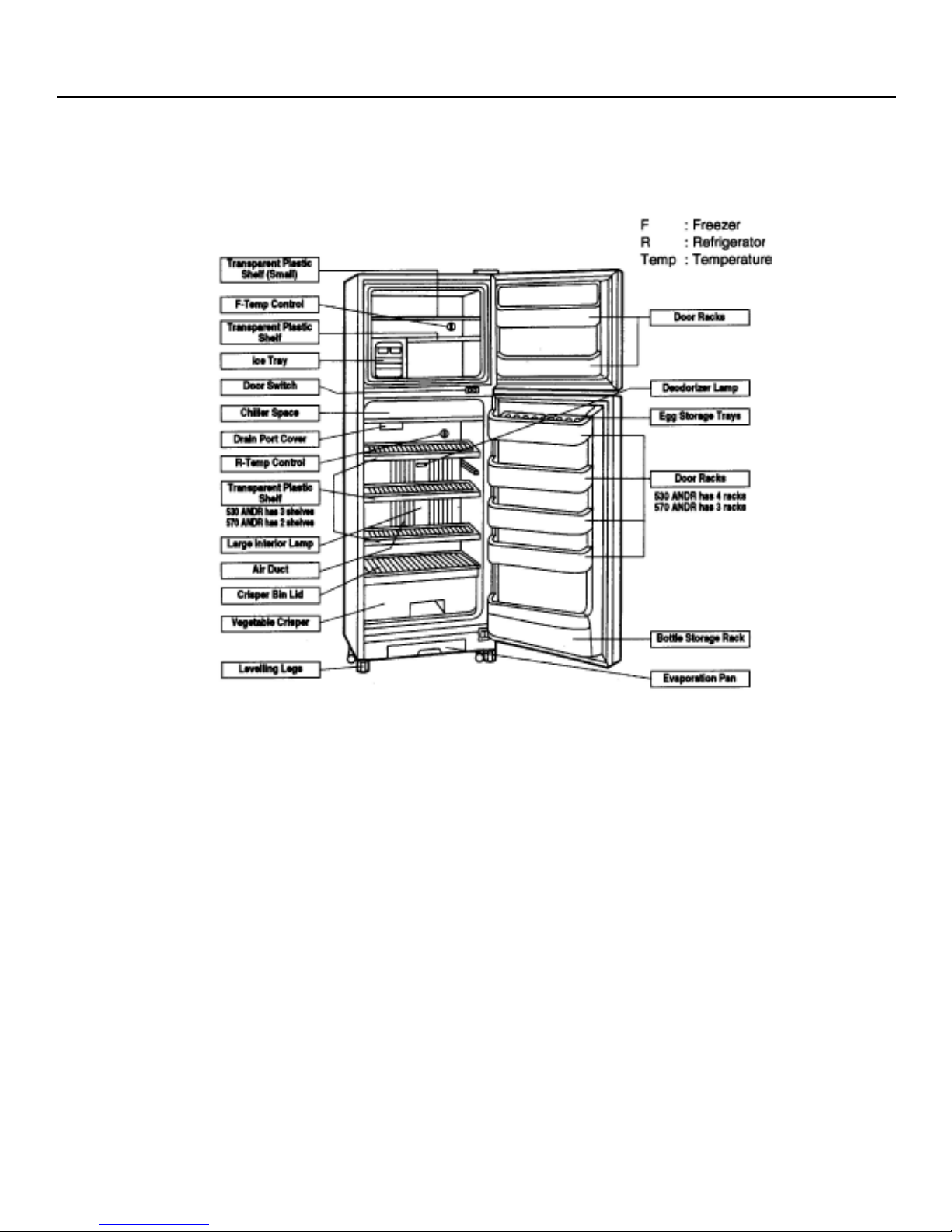
TBG530ANDR / TBG570ANDR
TBQ530ANDR / TBQ570ANDR
TBR527ANDR / TBR565ANDR
III. PARTS IDENTIFICATION
Note : Because of ice expansion, containers with water may deform in the freezer.
3.2 FEATURES
Ice Tray : Can make and store 1 kg of ice cube.
Temp Controlled Meat Keeper : The fish and meats which will be cooked within 2 days can store here, no
Evaporation Pan : Water discharged from the refrigerator is evaporated here.
Door Racks (F) : Short-term storage of frozen food.
Egg Storage Basket : Can store 20 eggs
Door Racks (R) : Short-term storage of refrigerated food.
Bottle Storage Rack : Can store 5 bottles of beer or soda.
Regulator : For regulation of the refrigerator.
thawing is required.
Page 8
TMQ / TMR / TMQ432ANDR
III. PARTS IDENTIFICATION
Note : Because of ice expansion, containers with water may deform in the freezer.
3.3 FEATURES
Ice Tray : Can make and store 1 kg of ice cube.
Temp Controlled Meat Keeper : The fish and meats which will be cooked within 2 days can store here, no
Evaporation Pan : Water discharged from the refrigerator is evaporated here.
Door Racks (F) : Short-term storage of frozen food.
Egg Storage Basket : Can store 20 eggs
Door Racks (R) : Short-term storage of refrigerated food.
Bottle Storage Rack : Can store 5 bottles of beer or soda.
Regulator : For regulation of the refrigerator.
thawing is required.
Page 9

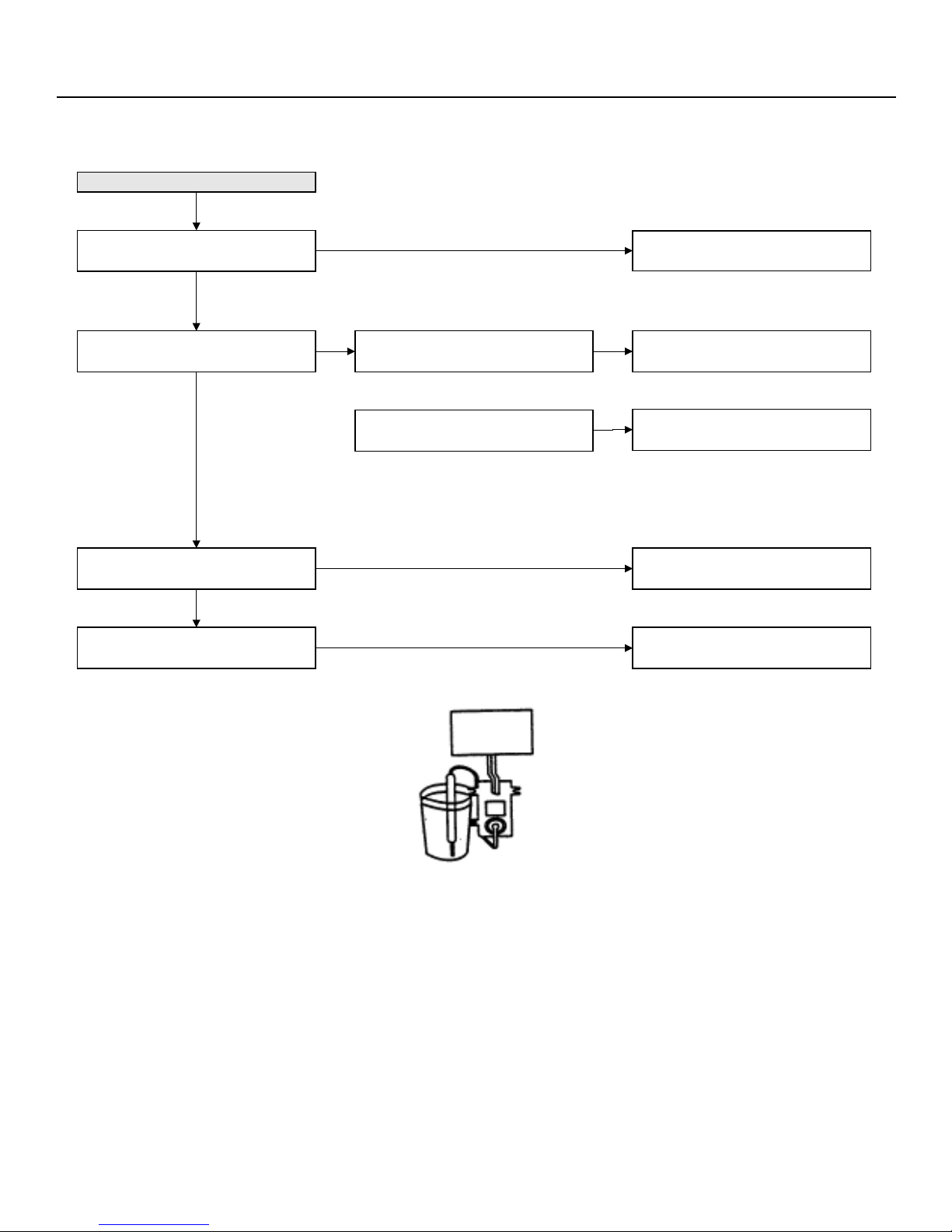
4.1 DEFROSTING
4.1.1 No defrosting operation is
necessary
No defrosting operation is necessary.
As this machine is so designed that a
built-in evaporator cools air and a fan
circulates cooled air, neither the
freezer nor the refrigerator is frosted,
though the evaporator is frosted.
The frosted evaporator is defrosted
automatically due to the function of
defrosting timer and heater, requiring
no defrosting operation.
4.1.2 Where is melted ice brought
IV. FUNCTIONS
i. Melted ice is brought into the
evaporating pan at the bottom of
the set and is evaporated here
by the heat of sub condenser.
ii. Be sure to use the evaporating
pan as inserted so as to be level
with the outer case.
Page 10
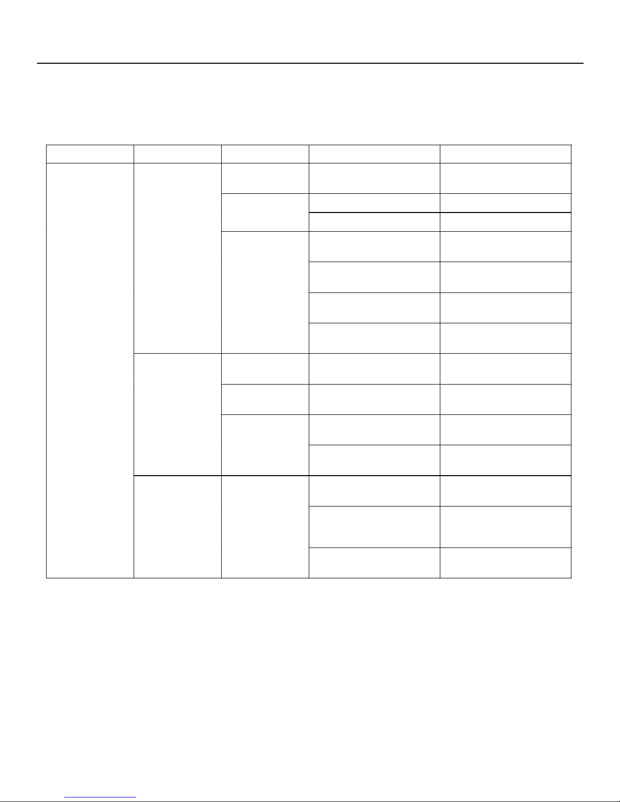
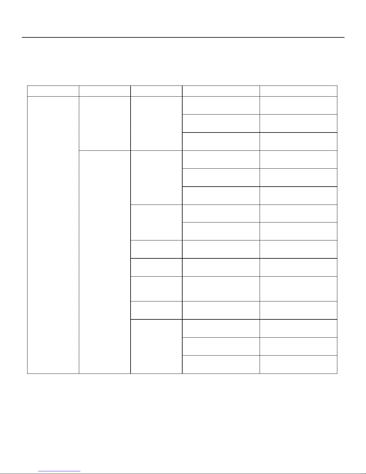
IV. FUNCTIONS
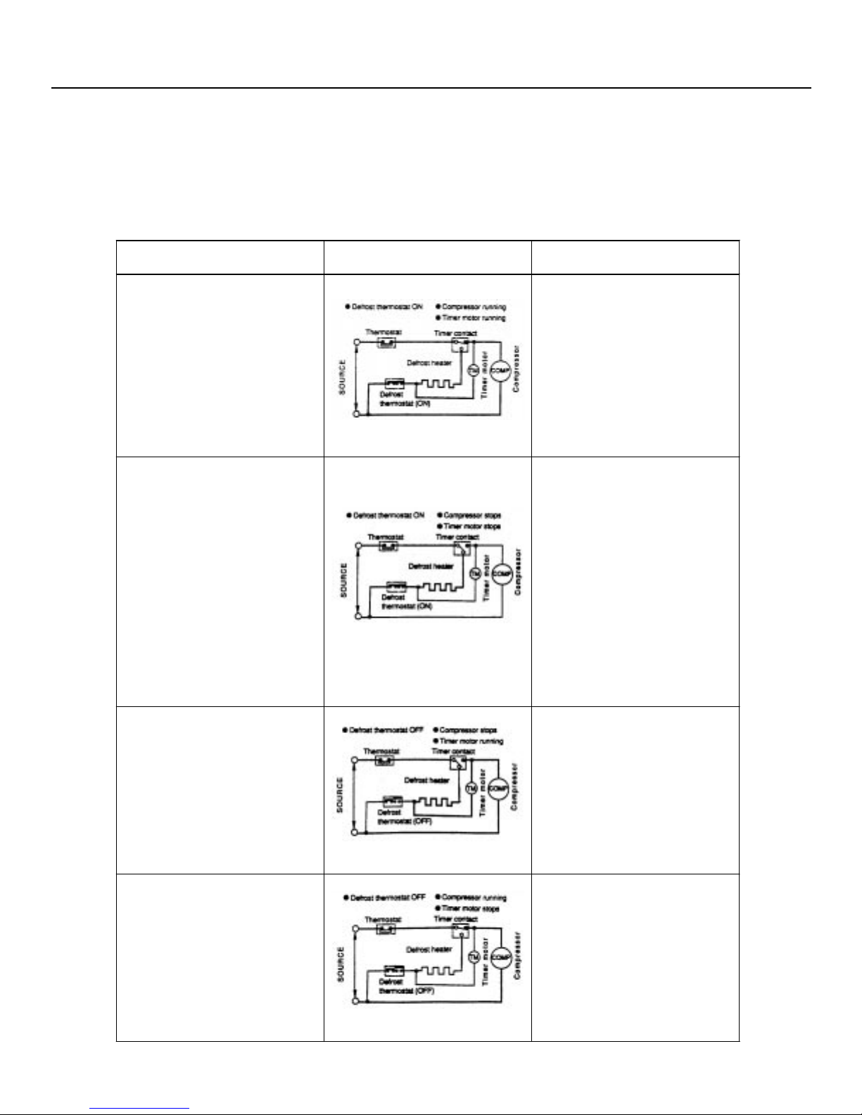
4.1.3 The following circuit diagrams in the table show automatic defrosting function of the refrigerator with time
and defrost thermostat.
Operation Electric Diagram Description
Cooling (Normal)
Defrosting
(Time 20 to 30 min.)
Fig 1
Fig 2
The integration timer
integrates running time of the
compressor. When it reaches
8 hours 50 min. at 50Hz, the
timer contact is changed to
start defrosting.
The timer contact is
·
changed to start
defrosting, the timer motor
stops, and power is
supplied to the defrost
heater.
It takes about 20 to 30
·
min. to defrost. When little
frosted the defrosting
takes little time. When
much frosted, the
defrosting takes much
time.
Drain (Time approx. 3 min.)
Cooling (Start)
(Time approx. 5 min.)
Fig 3
Fig 4
Page 11
When the defrost thermostat
becomes OFF, the timer motor
at rest starts running. During
the operation time (2 MIN, 48
SEC / 50 Hz) defrosted water
is drained outside the
refrigerator.
Timer contact is changed
·
to cooling operation and
the compressor starts
running and the timer
motor stops.
Defrost thermostat contact
·
becomes ON when its
cooled. (Figure F-1)
IV. FUNCTIONS
4.1.4 As a reference to determine the causes of
trouble, malfunction and phenomena are
described below. Refer to the following
when repairing.
i. Disconnection of defrost heater
As off-cycle defrosting is performed, the
defrosting time is extremely prolonged.
Each time defrosting is started, the
freezer temperature rises and a portion
of ice and stored foods are melted.
ii. Melted thermo fuse or opened-circuit
due to the defect of defrost thermostat.
When the above mentioned trouble
occurs in cooling operation, the timer
motor does not run, defrosting will not
take place, and consequently freezing is
caused. In the above mentioned
condition, when the time shaft is turned
by hand to defrost, the timer motor runs
during the operation time. However, the
motor stops from the time wien the
contact is changed, and freezing
causes.
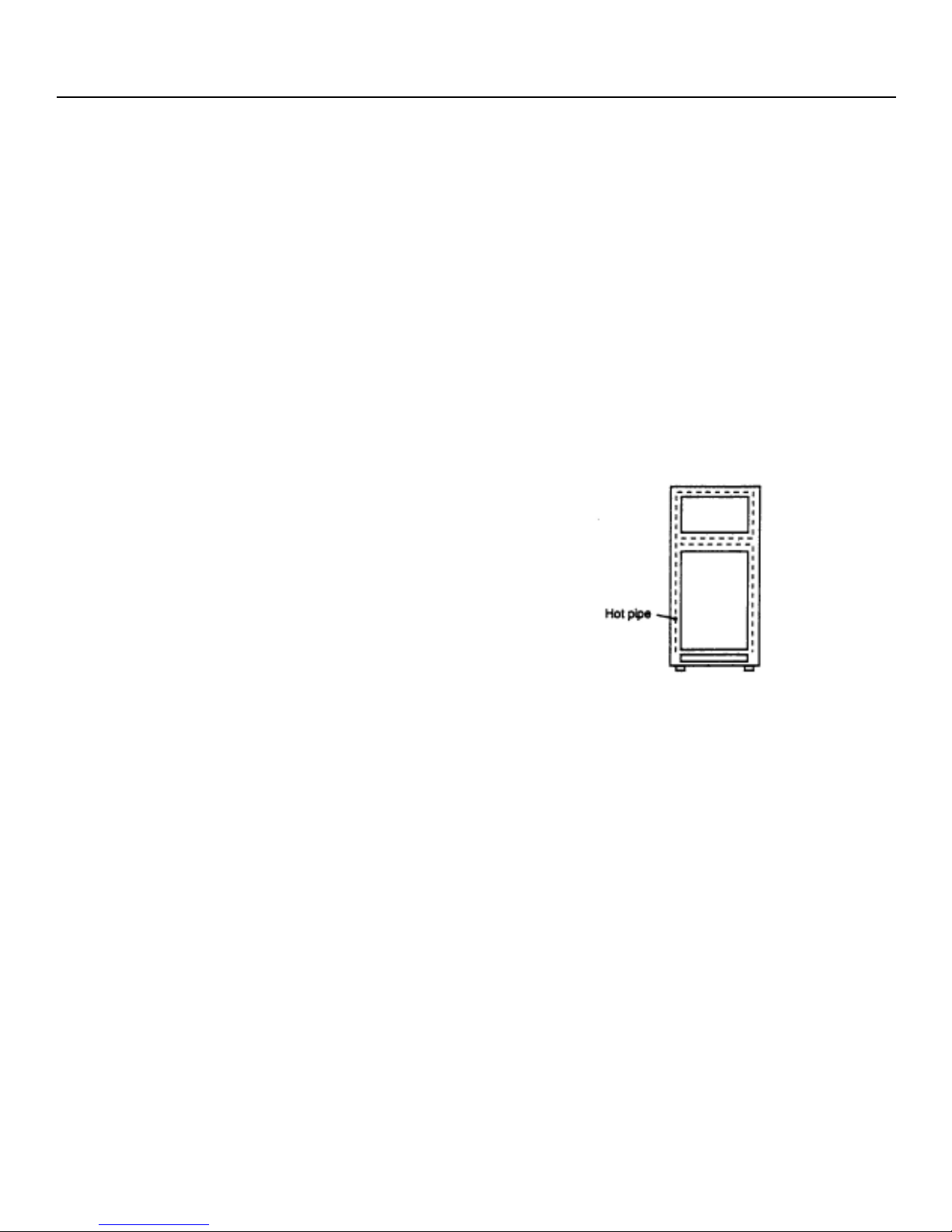
4.2 DEW PREVENTION
The hot pipe, namely D P condenser, is arranged
around the flange part of cabinet and the C-partition
plate, preventing dew from being generated on the
cabinet.
Note :
i. D P Condenser pipe may be felt hot if touched
by hand while the compressor is in operation.
ii. If you are asked about this, please explain that
the hot pipe serve to prevent the dew
generation.
Note :
As the thermo fuse assembly is
intended to prevent dangers, do not use
it under shorted condition even for a
short period.
Page 12

IV. FUNCTIONS
4.3 INSPECTION OF INITIAL STARTING
4.3.1 Inspection of Cooling Unit
i. Set the temperature control knob to
MAX and check that the
compressor starts to operate.
ii. Check that cool air is blown out of
the cold air outlet of the freezer and
the refrigerator.
iii. when the compressor does not
work, check that the timer is not set
to defrost position.
iv. It takes about an hour and a half or
two hours to put food in the
refrigerator after starting operation.
Note :
- After return the temperature
control knob to MED position.
- When the refrigerator is
operated initially after installed,
the compressor may vibrate
excessively for 1 to 2 min.
However, vibration becomes
normal if it is continuously
operated.
4.3.2 Inspection of defrost device
Operate the refrigerator for 20 to 30
min. and then check the defrost device
in the following procedures. Allow 5
min. to restart the compressor since
immediate starting after stopping will
cause unsmooth operation.
i. Turn the timer shaft clockwise with
a screw driver. At this time, make
certains the timer clinks and the
compressor stops.
ii. After more than 5 min., turn the
shaft further to operate. Make
certain cooling operation is started
again.
Note :
- Its not necessary to switch the timer
by changing of source frequency
(50Hz 60Hz)
Page 13
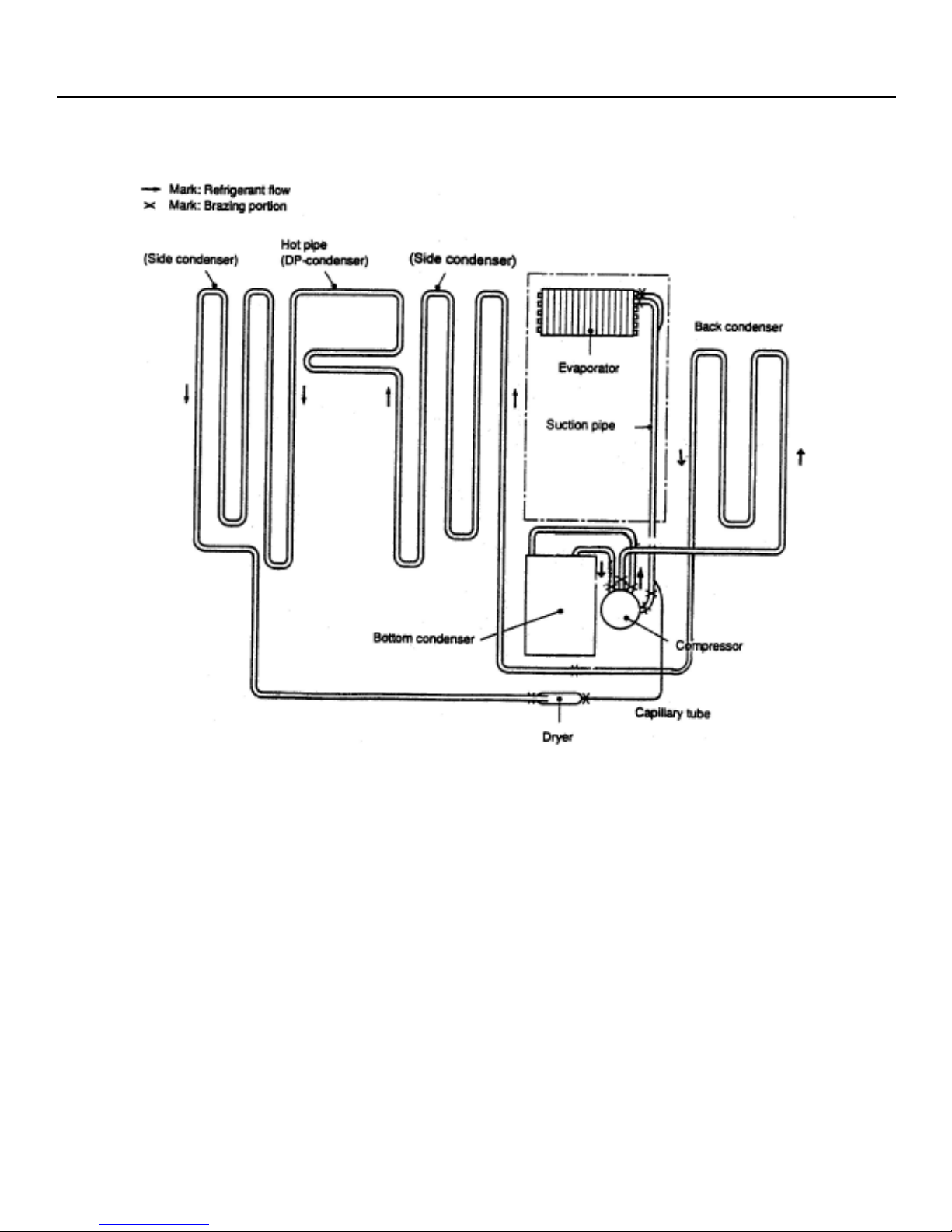
IV. FUNCTIONS
Figure 1 - Cooling Unit
Page 14

V. ADJUSTMENT
5.1 COMPRESSOR
5.1.1 Role
The Compressor inhales low temp.
and low pressure gas evaporated
from Evaporator of the refrigerator,
and condenses this gas to high temp.
and high pressure gas, and then
plays delivering role to Condenser.
5.1.2 Composition
The compressor is composed of
Compressor Apparatus compressing
gas. Compressor Motor moving
Compressor Apparatus and Case
protecting Compressor Apparatus
and Motor.
There are PTC-Starter, and Over
Load Protector in the Compressor
outside.
v. Be careful that dust, humidity, and flux
due to welding dont inflow in
Compressor inside in replacing
Compressor. Dust, humidity, and flux
due to welding which inflows to
Cylinder may cause lock and noise.
On the other hand, because the
Compressor consists of 1/1000mm
processing precision components
and is sealed after producing without
dust or humidity, deal and repair with
care.
5.1.3 Note to Use
i. Be careful not to allow over
voltage and over current.
ii. No Strike
If applying forcible power or strike
(dropping or careless dealing),
poor operation and noise may
occur.
iii. Use proper electric components
appropriate to the compressor.
iv. Note to keep Compressor
If Compressor gets wet in the rain
and dust in the pin of Hermetic
Terminal, poor operation and poor
contact may cause.
Page 15

V. ADJUSTMENT
5.2 PTC-STARTER
5.2.1 Composition of PTC-Starter
i. PTC (Positive Temperature
Coefficient) is no-contact
semiconductor starting device which
uses ceramic material and the
material consists of BaTiO3.
ii. The higher the temperature is, the
higher resistance value becomes.
These features are used as starting
device of motor.
5.2.2 Role of PTC-Starter
i. PTC is attached to hermetic
Compressor used for refrigerator,
show case and starts motor.
ii. Compressor for household
refrigerator applies single-phase
induction motor. For normal
operation of single-phase induction
motor, in the starting operation flows
in both main coil and sub coil. After
the starting is over, the current is cut
off in sub coil. The proper features
of PTC play the above all roles. So,
PTC is used as a starting device of
motor.
5.2.4 Relation of PTC Starter and OLP
i. If power off during operation of
Compressor and power on before
PTC is cooled, (instant shut-off within
2 min. or reconnect a power plug due
to misconnecting), PTC isnt cooled
and a resistance value grows. As a
result, current cant flow to the subcoil and motor cant operate and OLP
operates by flowing over current in
only main-coil.
ii. While the OLP repeats on and off
operation about 3-5 times, PTC is
cooled and Compressor Motor
performs normal operation.
If OLP doesnt operate when PTC is
not cooled, compressor motor is
worn away and cuases circuit-short
and fire. Therefore, use a proper
fixed OLP without fail.
5.2.5 Note to Use PTC-Starter
i. Be careful to over voltage and over
current.
ii. No Strike.
Dont apply a forcible power or strike.
5.2.3 Motor Restarting and PTC Cooling
i. For restarting after power off during
normal Compressor Motor operation,
plug the power cord after 5 min. for
pressure balance of refrigerating
cycle and PTC cooling.
ii. During normal operation of
Compressor Motor, PTC elements
generate heat continuously.
Therefore, if PTC isnt cooled for a
while after power off, Motor cant
operate again.
iii. Keep apart from any liquid
If liquid such as oil or water inflows
into PTC, PTC materials may break
due to insulation breakdown of
material itself.
iv. Dont change PTC at your
convenience.
Dont disassemble PTC and mold.
If damaging to outside of PTCStarter, resistance value alters and
poor starting of Compressor motor
may cause.
v. Use a properly fixed PTC.
Page 16

V. ADJUSTMENT
5.3 OLP (OVER LOAD PROTECTOR)
5.3.1 Definition of OLP
i. OLP (Over Load Protector) is
attached to hermetic Compressor
and protects motor by cutting off
current in Compressor motor by
Bimetal in the OLP in case of overrising temperature.
ii. When oven voltage flows to
Compressor motor, Bimetal works by
heating the heater inside OLP, and
OLP protects motor by cutting off
current which flows to compressor
motor.
5.3.2 Role of OLP
i. OLP is attached to hermetic
Compressor used to refrigerator and
show case and prevents motor coil
form being started in the
Compressor.
ii. Do not turn the Adjust Screw of OLP
in any way from normal operation of
OLP.
Page 17
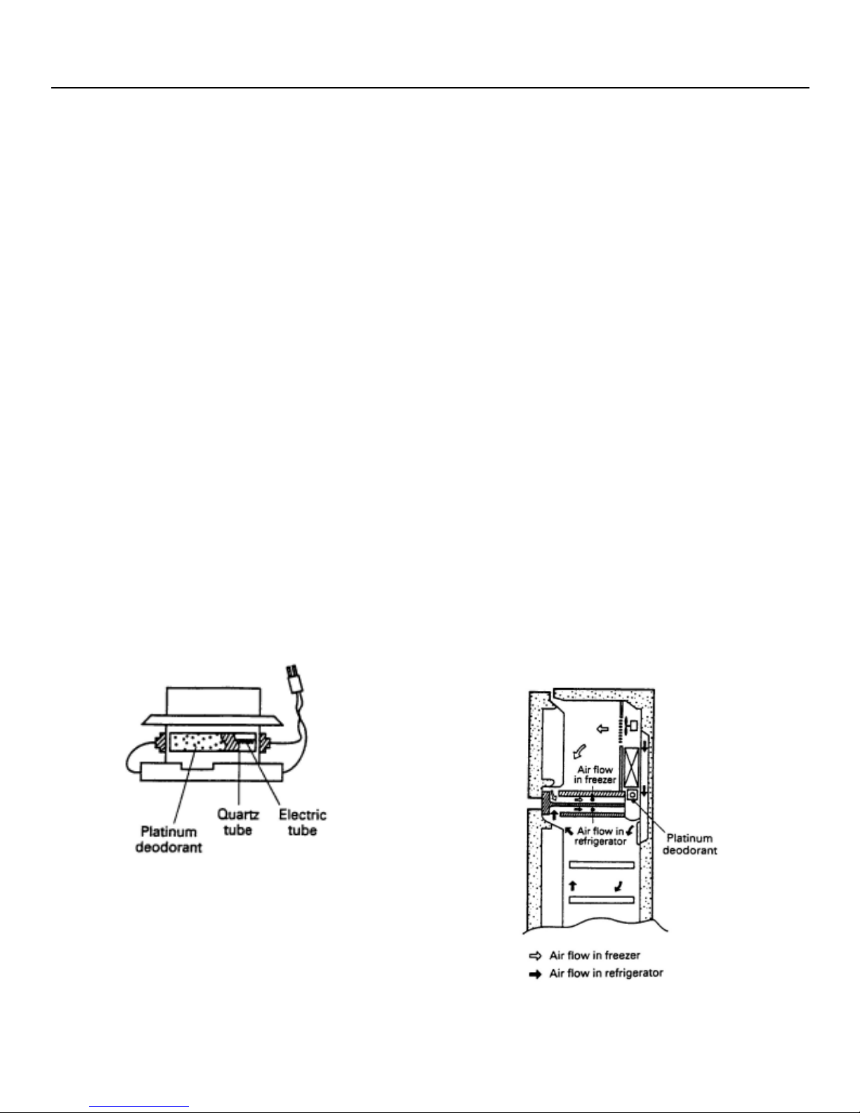
VI. DEODORIZATION WITH PLATINUM
6.1 DEDORIZATION WITH PLATIMUM
6.1.1 This material is used for
Deodorization and defrosting
because of its high temperature
acidification to get rid of odors in the
refrigerator.
6.1.2 This is a platinum-based catalyst
deodorant evenly coated on the
quartz tube. It is a highly active and
adhesive metal.
6.1.3 In the refrigerator, the odor passes
by the deodorant catalyst and is
attracted by the deodorant coated on
the quartz tube.
6.1.4 When defrosting, the 250°C heat
produced in the quartz tube dissolves
the acidified odor and purifies the
cold air in the refrigerator.
6.1.5 After defrosting, the clean and odorfree cold air refrigerates the food. At
the next defrosting, it carries out
Deodorization and this process is
repeated.
6.2 APPLICATION OF PLATINUM AS
DEODORANT
6.2.1 A fan is used in the frost-free refrigerator
for refrigeration.
6.2.2 The Platinum deodorizer is installed
beneath the cooler at the cold air outlet
that cools the freezer compartment.
Because the refrigerator is a sealed
cabinet, the rotating cool air is forced to
rotate by the fan and cause odor to pass
through the deodorizer.
6.2.3 When not defrosting, the deodorant is
highly activated and odor is absorbed.
6.2.4 After running for a while and during the
defrosting stage, the heat produced by the
defrosting heater that goes through the
quartz tube to the deodorant on the
surface at over 250°C, causes odor to
attach to the deodorizer where it is
acidified into pure gas, free of odor.
6.2.5 At the end of defrosting, the fan resumes
work and the high temperature does not
go down. The acidified gas causes the
deodorant to continue to absorb odor.
Diagram of Defrosting Heater
Page 18
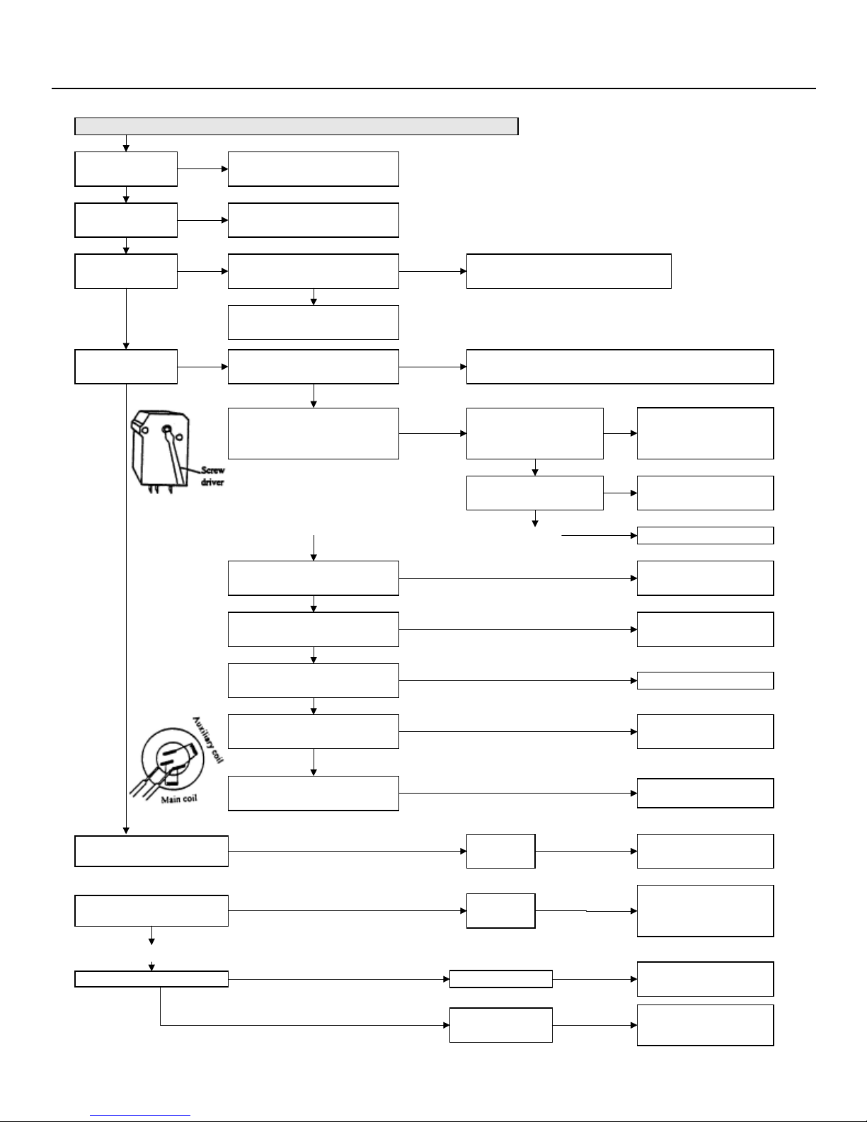
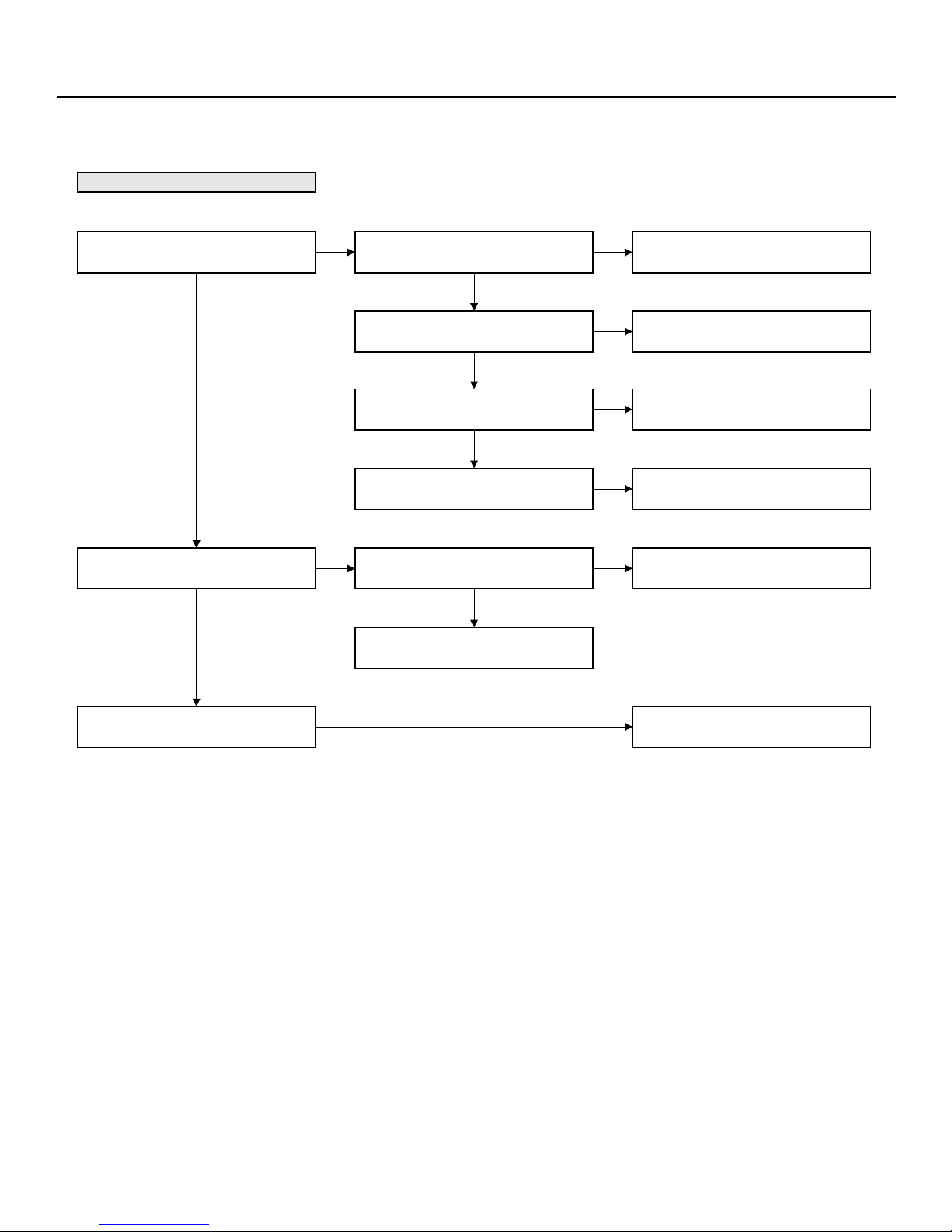
VII. FAILURE DIAGNOSIS
1. Not cold at all (freezing storage and cooling chamber are not cold)
Is the plug being
inserted?
Yes
Is the plug being
inserted?
Yes
Is the voltage over
99V?
Yes
Is the compressor
operating?
No
No
No
No
Insert the power plug.
Any shutdown? Check the abnormal
power cord or switch
Is a special socket used by the
refrigerator?
Is the geographical environment being
using a special one?
Short the F thermostat and see if the
compressor is operating.
When regulat e D meter to cooling
operation side, is the compressor
operation?
Non-operating
No
Yes
Operating
Not operated
Operating
* Turn D time to right side
till heating two noises
Is a socket affected by other electrical wiring?
Change F-THM, then check is it due to the freon leakage of thermo
Is the temperature fuse
Is temperature switch
sensor or by poor contacting point?
No
melted?
Engaged
No
engaged?
Replace the temperature fuse
Replace the temperature
switch
Replace D meter.Engaged
Short the overload protector and see if
the compressor is operation.
Yes
Is the relay of PTC starter normal?
Is the capacitor normal at starting or
The contacting point being poor? Repair the contacting point.
Is the circuit of compressor coil
Ice beads or serious frost formed
Inspection of the frosted cooler
Non defrost
Inspection of freon leakage Freon leakage
No freon leakage
Defective freon circuit Clogged by impurities
The lower pressure tube of
compressor fails to such the air.
in the cooler chamer
Check the leakage
location
operating?
Freon circuit
clogged
Non-operating
Yes
Yes
No
normal?
Operating
Abnormal
Abnormal
Yes
Abnormal
Poorly
defrosted
Poor compression of
the compressor
Replace the overload
protector.
Replace the relay of PTC
starter.
*Impedance short (0Ω) and poor circuit (0∞)
Replace the capacitor.
*In case of the normal item, the needle of the
panel will become (∞Ω) after one vibration.
* Remove the pin from the connecting point and
check if it has turned into black.
Replace the compressor and
drying filter.
* Check the circuit of mail coil, auxiliary coil
and resistance value.
Refer to the mothod of non-
defrost
Poor location be repaired.
Replace the compressorm
drying filter. Clean the freon
circuits.
* When the inner side of compressor is too dirty,
it must be replaced.
Replace the clogged parts.
Replace the drying filter.
Clean the freon circuit
Replace the compressor,
drying filter. Clean the freon
circuit.
Page 19
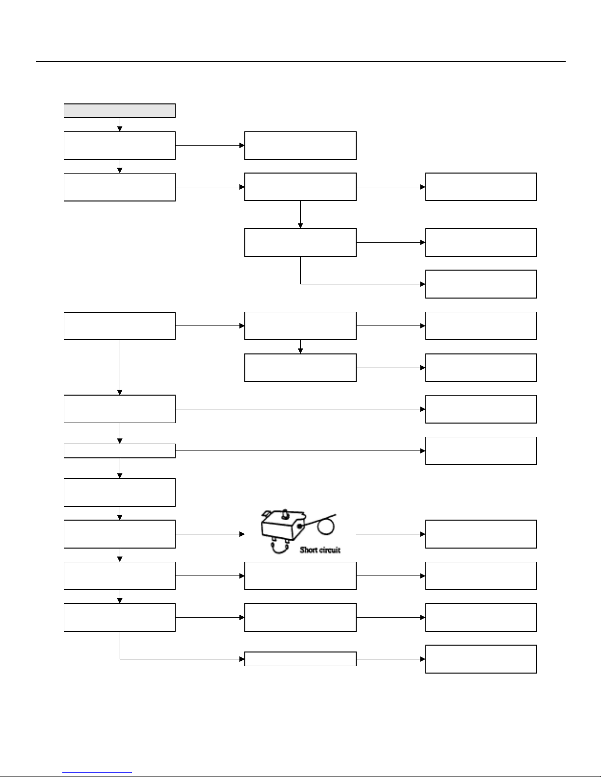
2. Not cold enough
VII. FAILURE DIAGNOSIS
Is the turn button set at "MAX"
position?
No
Setting the temperature of
each chamber in the storage.
High temperature
Set the turn button to
"Medium" and confirm
High temperature
in the freezing storing
and the cooling
chamber
Is the storage environment
appropriate?
Yes
Is the storing method of the
food inside the storage room
appropriate?
Yes
Only freezing
room (including
0°C room)
No Yes
Is the turn button set at "MAX"
position?
Confirm the bumper cohesion
of bumper thermostat
Opened
Any clearance at the door
knob?
No
The ambient space of the
refrigerator being too small
No
The ambient temperature of
the refrigerator being too high.
No
Fully closed
Yes
Yes
Replace bumper thermostat
(Freon leakage at the thermo
sensor of bumper thermostat)
Adjust door and replace the
door knob
Frequent opening of door.
Insufficient convection of cold
air due to over loaded food.
Adjust the storing place of
refrigerator
Avoid direct sun beam or
move the gas stove away from
the refrigerator.
Note if the food stored inside
the storage room being too
much.
Yes
The clearance of door knob
No
Mist and frost formed at the
top of freezing chamber and
quick freezing chamber.
No
Will F thermostat become cold
after the short circuit?
No
Is the fan in the storage room
operated normally?
Yes
Confirm the frosting of the
cooler.
Frozen or frosted in
the cooler chamber
Yes
No
Yes
Is the motor of fan operated
normally?
Inspect the freon leakage
location
Poorly defrosted
Adjust door and replace door
Replace the motor of fan
YesMinor frost
Defect repairs and replace the
Refer to the method of non-
knob
Replace F thermostat
drying filter
defrost
Page 20
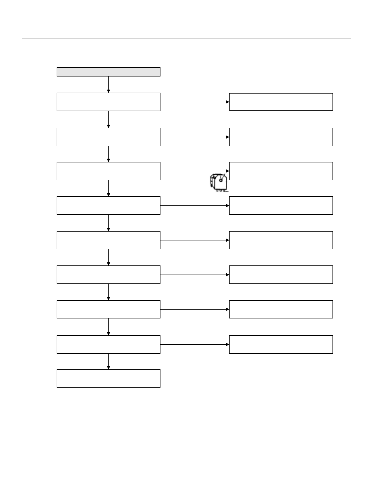
3. Fail to Defrost
VII. FAILURE DIAGNOSIS
Confirm the frosting of the cooler
more
frost
Is the coil circuit of D meter working? Replace D meter (broken coil)
Yes
Turn the pin of D meter to defrost side. Is the
circuit of defrost heater working?
No
Is the circuit at the defrost side of D meter
working?
Yes
Short circuit at the temperature switch, is the
circuit of defrost heater working?
No
Is the circuit of defrost heater working? Replace the defrost heater.
Lesser frost
No
Green & black circuit of D
meter
Defrost
Yes
No
Green & black circuit of D
meter
Yes
No
Clearance of door knob and forget to close the
Agent
Replace D meter (poor operation of D meter)
Replace D meter, (poor contacting point)
freezing chamber door.
Replace the temperature switch.
Yes
Is the circuit of temperature fuse working? Replace temperature fuse.
Yes
Is the circuit of water dripping tray working? Inspect the heater of water dripping tray.
Yes
Clean the water and impurities in the water
dripping tray.
No
No
Page 21
4. Too cold
VII. FAILURE DIAGNOSIS
Is the turn button set at "Strong Position"? Turn the button at "Weak" Position.
No
Temperature set of each chamber in the
storage room.
Turn all the buttons to
"Medium" for
confirmation.
Low temperature
Confirm the cohesion of bumper thermostat Replace the bumper thermostat
Closed
Mist and frost formed at the top of freezing
chamber and quick freezing chamber.
* If setting the button of the freezing chamber at
"Strong" while the cooling chamber is at "Medium",
then the cooling chamber and fressness-keep
chamber will become too cold.
Is the ambient temperature below 5°C?
Only for the freezing of food near the suction
outlet of bumper thermostat.
* When the food containing more moist (bean curd,
vegetable, fruit, etc) is placed at the inner side of
shelve or the freshness-keep chamber, then the food
would be easily frozen. So, it is necessary to change
* Use ice to cool the thermo sensing part for confirmation.
* Freezing phenomenon formed at the bumping part of the
Yes
the storage method.
Opened
Yes
bumper thermostat.
YesNormal
Yes
Turn the button to "Weak" position.
Change the storing method of the food.
Forget to close the freezing chamber door.
Repair the contact of food and door rail.
* When the bumper thermostat is replaced
due to poor cooling, be sure not to install the
cooling chamber bumper correctly and it must
be secured on the original leverage.
* Put iced water in to the cup or placed it into
the freezing chamber to cool it down, so as to
confirm the action of the bumper.
Page 22
5. Unusual Noise
VII. FAILURE DIAGNOSIS
Unusual noise during the compressor running
in the mechanical room.
If any unusual noise of the fan (upon opening
the door)?
No
unusual
noise
Yes
Yes Yes
Is the ground horizontally flat?
Yes
If the mechanical piping being slanted or
contacted.
No
If all the piping in the mechanical room are
resonant.
No
Inspect the vibration of compressor and adjust
the rubber pad to reduce vibration.
Check if the fan is contacting EV cover or the
grate.
No
Inspect the assembly of fan and grate and
adjust it to create air tightness with the inner
case.
No
Yes
Yes
Yes
Adjust by the adjusting foot.
Be properly adjusted.
Adjust the location of counter-weight
Change the storage method of the food.
Press down the fan to the end to confirm that
the fan will not contact the grate.
Unusual noise in D meter
Open the electrical case and replace new D
meter.
Page 23
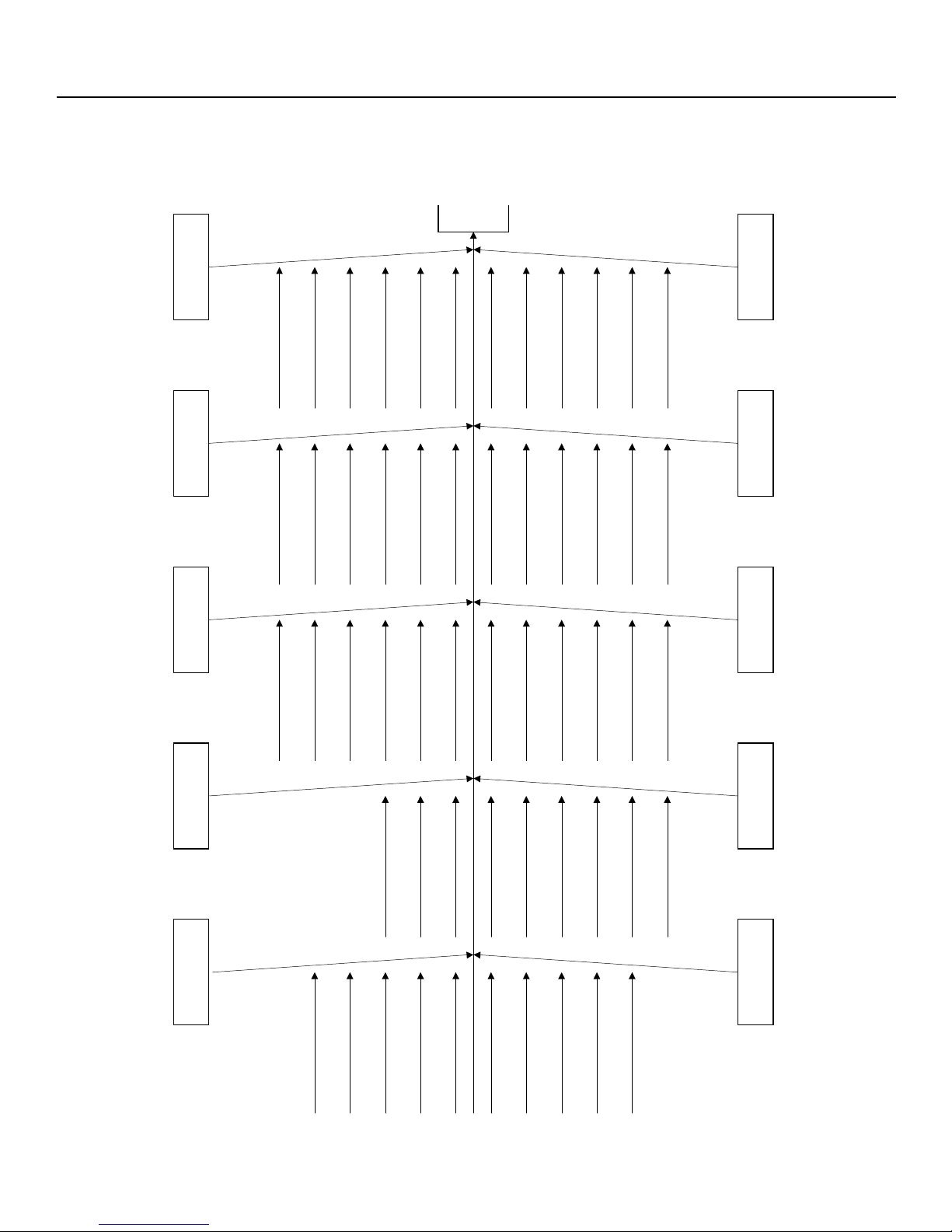
VII. FAILURE DIAGNOSIS
g
o
r
in
sto
High
refri
C. Slight air leakage A. Too much freon.
Discharge tube temp. being
(suction tube)
E. Clogged by dusts
Slight raise of heatdissipater
tube.
High suction pressure.
not too high.
temperature
Frosted or fogged suction
Low suction pressure Fair heat dissipater temp. High current & power
over -18°C
and heat dissipater
Inadequate coldness
High temp. at discharge tube
Evaporator temperature being
Low current & power
Frosting being clogged
Almost no frosting
Inadequate coldness
Inadequate coldness
Without flowing sound
Almost no frosting
Poor freezing effect
Low current & power
Cycle frost & mist
Change of current & power
Change of suction pressure
Inadequate coldness
High current & power
Frosting being clogged
Low suction pressure
Low heat dissipater temp.
Low discharge tube temp.
Intermittent raise of
dissipater temperature
Intermittent raise of heat
Intermittent flowing sound
Low suction pressure
compressor temperature
clogged by dust
Unusual noise at the
High compressor temp.
discharge section due to
D. Water clogging B. Insufficient Freon
exhaust
F. Dusts clog the
cannot be
condensated.
G. Containing air that
I. Air leakage
dissipator not raised
Temperature at the heat
High current & power
High suction pressure
low
low.
Without flowing sound Low current & power Low suction pressure
Current & power being too
Temp. discharged being too
Inadequate temperature
Being not cold
Inadequate coldness
Normal frosting
Page 24
Low current & power
High suction pressure
High current & power
Low heat dissipater temp
Sound of oil flow
Normal suction pressure
suction tube
cannot be frosted
No temperature difference
between discharge tube and
No flowing sound and almost
J. Over filled oil H. Poor compressing
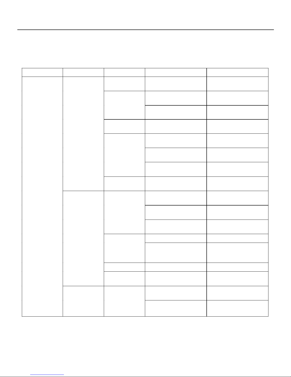
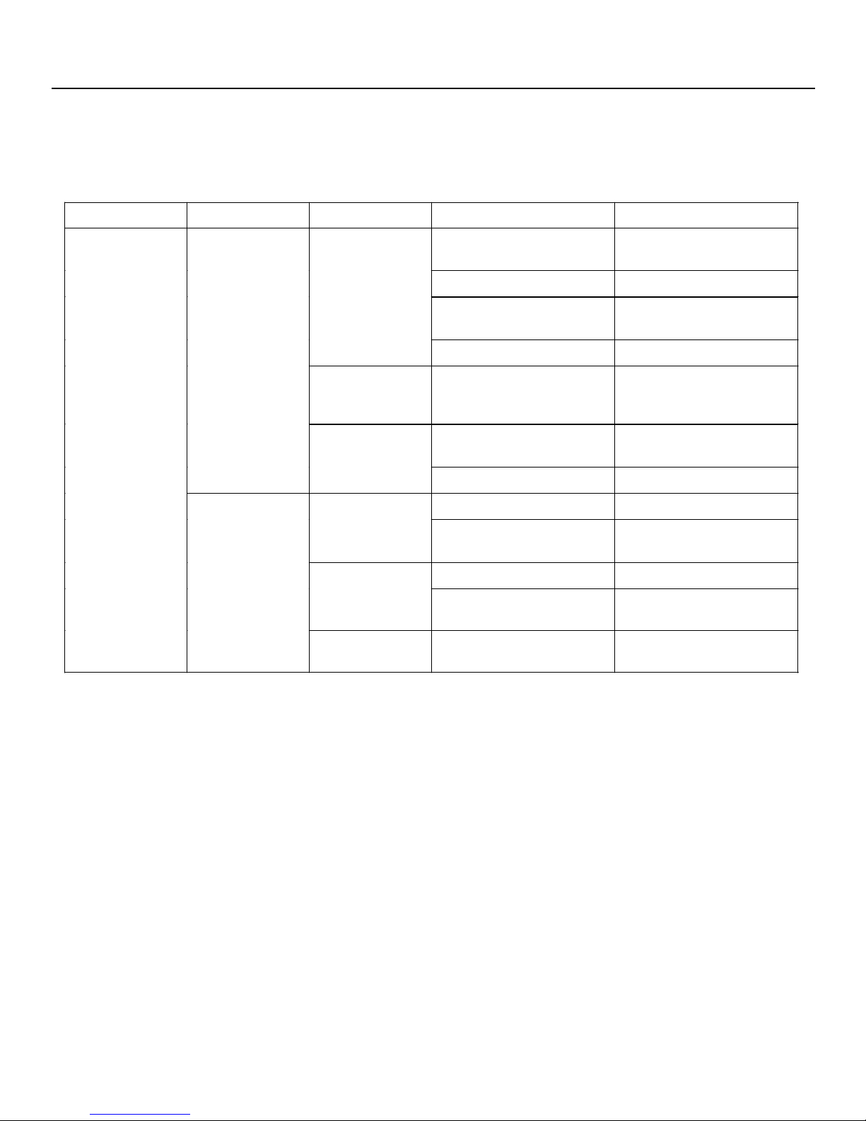
VII. FAILURE DIAGNOSIS
CAUSES & TREATMENT OF REFRIGERATOR FAILURES
Phenomenon Failure Condition Inspection Part Causes Treatment Actions
Refrigerator fails
to operate
Electric current
meter remains
still
Instant power
stop of major
motor
Electric power 1. Power cord not being
engaged
Compressor
Relay Broken electrical heating
Control Switch
Defrost Switch 1. Poor practice
Compressor
1. Broken main coil of the
motor.
2. Broken wiring of the
refrigerator.
wire
1. Button set at OFF
position.
2. Poor practice
3. Air leakage (freon).
1. Choking
2. Short circuit between
motor
Any power shut off or
·
melted fuse?
Replace the
·
compressor
Check & repairs
·
Replace the relay
·
Replace the control
·
switch
Replace the control
·
switch
Replace the control
·
switch
Replace the defrost
·
switch
Replace the
·
compressor
Replace the
·
compressor
Defrost switch
fails to recover
or longer time
needed for
recovery
3. Broken auxiliary coil of
the motor.
Starter
Capacitor 1. Burnt out
Power 1. Abnormal voltage
Defrost switch
1. Poor practice
2. Poor contacting point
1. Poor practice
2. Low room temperature
Page 25
Replace the
·
compressor
Replace the starter
·
Contacting point be
·
polished or replaced
with a new one.
Replace the capacitor
·
Explanation for the
·
customer.
Replace the defrost
·
switch
Explanation for the
·
customer.
VII. FAILURE DIAGNOSIS
CAUSES & TREATMENT OF REFRIGERATOR FAILURES
Phenomenon Failure Condition Inspection Part Causes Treatment Actions
Operation time
being too long
Compressor fails
to control the
stop
Bigger power
consumption
Control Switch 1. Poor practice
Door Knob
Others
Control Switch 1. Inappropriate position
Electric power 1. Voltage being too high.
Others
1. Poor knob
2. Poor door clearance
1. Too much food being
stored.
2. The food stored being
too warm.
3. Door opening being too
frequent.
4. Improper storage
location.
of turn button.
1. Too much food being
stored.
2. Improper storage
location.
Replace the control
·
switch
Replace the door knob
·
Be adjusted.
·
Explanation for the
·
customer.
Explanation for the
·
customer.
Explanation for the
·
customer.
Explanation for the
·
customer.
Explanation for the
·
customer.
Explanation for the
·
customer.
Explanation for the
·
customer.
Explanation for the
·
customer.
Temperature
being too low
Control Switch
1. Inappropriate position
of turn button.
2. Poor contact between
thermo-sensing tube
and evaporator.
3. Poor practice.
Page 26
Explanation for the
·
customer.
Be adjusted.
·
Replace the control
·
switch.
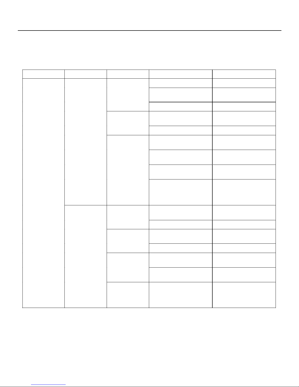
VII. FAILURE DIAGNOSIS
CAUSES & TREATMENT OF REFRIGERATOR FAILURES
Phenomenon Failure Condition Inspection Part Causes Treatment Actions
The refrigerator
being operated
but not cold.
Not cold at all Freezing System
Not cold even
after longer time
of operation
Freezing system
Door knob
Evaporator 1. Too thick of frost
Control Switch 1. Inappropriate position
1. Freon leakage.
2. Clogged by dusts and
moisture.
3. Defective pressure
exhaustion.
1. Insufficient freon
2. Clogged by dusts and
oil
3. Poor discharge
1. Poor clearance of door
knob
2. Defective door knob
of the turn button.
Replace / Repair the
·
freezing system
Replace / Repair the
·
freezing system
Replace / Repair the
·
freezing system
Replace / repair the
·
freezing system
Replace / repair the
·
freezing system
Replace / repair the
·
freezing system
Be adjusted.
·
Replace the door
·
knob.
Explanation for the
·
customer.
Explanation for the
·
customer.
Motor of the fan 1. Fails to turn.
Condenser 1. Being dirty or poorly
ventilated.
Others
1. Too much food being
stored.
2. Door opening being too
frequent.
3. Improper storage
location.
Page 27
Defrost switch, door
·
opening and wiring be
Inspected.
Explanation for the
·
customer.
Explanation for the
·
customer.
Explanation for the
·
customer.
Explanation for the
·
customer.
VII. FAILURE DIAGNOSIS
CAUSES & TREATMENT OF REFRIGERATOR FAILURES
Phenomenon Failure Condition Inspection Part Causes Treatment Actions
Noise
Louder noise
during the
operation and at
start, stop
Vibration during
start, stop and
operation (noise
heard from the
stored food and
from the articles
on the board)
Compressor
Contacting
vibration of each
part.
Noise from the
evaporating tray
Installation
Tubing
Compressor 1. Screw locking being
1. Being unusual inside.
2. Poor installation.
3. Voltage being too low
(below 90V).
4. Contacting noise
1. Poor installation and
fixed contact.
1. Inappropriate position
of the evaporating tray.
2. Poor flatness of base.
1. Poor leg regulating.
2. The floor being to
weak.
1. Tubing contact.
2. Poor shock absorption
of the tubing.
too tight.
Replace the
·
compressor.
Be adjusted.
·
Explanation for the
·
customer.
Be adjusted.
·
Be adjusted.
·
Explanation for the
·
customer.
Be adjusted.
·
Be adjusted.
·
Explanation for the
·
customer.
Be adjusted.
·
Be adjusted.
·
Be adjusted.
·
Page 28
VII. FAILURE DIAGNOSIS
CAUSES & TREATMENT OF REFRIGERATOR FAILURES
Phenomenon Failure Condition Inspection Part Causes Treatment Actions
Sweating
Sweating at the
outer surface
Overflow or
leakage or
internal sweating
Insulator
Anti-mist electric
heater.
Others
Door
Drainage device
being clogged
1. Poor mounting method.
2. Poor heat-insulating of
the tubing.
3. Wet insulator.
1. Broken wires.
2. Poor wiring.
1. Humidity being very
high.
2. Being stored highly
humidified place.
3. Incorrect using method
4. Poor generator being
installed
1. Poor clearance of door
sealing gasket.
2. Loosen door opening
1. Poorly sealed drainage
valve.
Accurate installation.
·
Add more insulator.
·
Replace the insulator.
·
Replace the anti-mist
·
electric heater.
Inspection & repairs.
·
Explanation for the
·
customer.
Explanation for the
·
customer.
Explanation for the
·
customer.
Improve the
·
installation and
replenish the
insulation.
Replace the door
·
sealing gasket.
Be adjusted.
·
Be adjusted.
·
Poor method
being used
Dripping tray
being unable to
sustain the
frosted water.
2. Clogged drainage tube.
1. Moisturized food being
unwrapped.
2. Frequent opening
during summer time.
1. Inappropriate storing
location.
Page 29
Clear for draining.
·
Explanation for the
·
customer.
Explanation for the
·
customer.
Explanation for the
·
customer.

VII. FAILURE DIAGNOSIS
CAUSES & TREATMENT OF REFRIGERATOR FAILURES
Phenomenon Failure Condition Inspection Part Causes Treatment Actions
Other
Electricity
leakage
Door opening
being not
smooth
Door opening
lamp not shown
Wiring & other
electrical
appliances
Door hinges and
stop lever.
Door knob 1. Defective clearance
Internal 1. Slanted door.
Lamp switch
inside the
refrigerator.
Lamp inside the
refrigerator
1. Insulation defect.
2. Static capacity
1. Loosening fixed part
2. Poor practice
3. Wearing
1. Defective contact
1. Broken wires
2. Poor lamp holder
3. Defective wiring
Repair the defective
·
part, and provide
explanation for the
customer, or use
earthing termina.
Repair the defective
·
part, and provide
explanation for the
customer, or use
earthing termina.
Be adjusted.
·
Be adjusted.
·
Be replaced.
·
Door be adjusted.
·
Be adjusted or
·
replaced.
Be adjusted.
·
Be adjusted.
·
Be adjusted.
·
Be inspected or
·
repaired.
Page 30
 Loading...