

GE
IISO 9001
G
N
E
I
L
M
I
U
T
L
T
E
S
I
R
G
E
E
D
R
LISTED
52TL
IND.CONT. EQ.
E83849
Grid Solutions
T60
Transformer Protection System
Instruction Manual
Product version: 7.4x
GE publication code: 1601-0090-AE3 (GEK-130989B)
1601-0090-AE3

Copyright © 2017 GE Multilin Inc. All rights reserved.
T60 Transformer Protection System Instruction Manual for version 7.4x.
T60, FlexLogic, FlexElement, FlexCurve, FlexAnalog, FlexInteger, FlexState, EnerVista,
CyberSentry, HardFiber, Multilin, and GE Multilin are trademarks or registered trademarks
of GE Multilin Inc.
The contents of this manual are the property of GE Multilin Inc. This documentation is
furnished on license and may not be reproduced in whole or in part without the permission
of GE Multilin. The content of this manual is for informational use only and is subject to
change without notice.
Part number: 1601-0090-AE3 (April 2017)

T60 Transformer Protection System
Table of contents
1 INTRODUCTION 1.1 Safety symbols and definitions.....................................................................1-1
1.1.1 General cautions and warnings ....................................................................................1-1
1.2 For further assistance .................................................................................... 1-2
2PRODUCT
DESCRIPTION
2.1 Product description......................................................................................... 2-1
2.2 Security.............................................................................................................. 2-4
2.3 Order codes ...................................................................................................... 2-8
2.3.1 Order codes with enhanced CT/VT modules........................................................... 2-8
2.3.2 Order codes with process bus modules ..................................................................2-14
2.3.3 Replacement modules .....................................................................................................2-20
2.4 Signal processing...........................................................................................2-23
2.4.1 UR signal processing ........................................................................................................2-23
2.5 Specifications ................................................................................................. 2-25
2.5.1 Protection elements ..........................................................................................................2-25
2.5.2 User-programmable elements ....................................................................................2-33
2.5.3 Monitoring..............................................................................................................................2-34
2.5.4 Metering..................................................................................................................................2-35
2.5.5 Inputs .......................................................................................................................................2-36
2.5.6 Power supply........................................................................................................................2-38
2.5.7 Outputs....................................................................................................................................2-39
2.5.8 Communication protocols..............................................................................................2-41
2.5.9 Inter-relay communications..........................................................................................2-42
2.5.10 CyberSentry security.........................................................................................................2-43
2.5.11 Environmental......................................................................................................................2-43
2.5.12 Type tests...............................................................................................................................2-44
2.5.13 Production tests..................................................................................................................2-44
2.5.14 Approvals ...............................................................................................................................2-45
2.5.15 Maintenance.........................................................................................................................2-45
3 INSTALLATION 3.1 Unpack and inspect......................................................................................... 3-1
3.2 Panel cutouts.................................................................................................... 3-2
3.2.1 Horizontal units ..................................................................................................................... 3-2
3.2.2 Vertical units........................................................................................................................... 3-3
3.2.3 Rear terminal layout ........................................................................................................... 3-8
T60 TRANSFORMER PROTECTION SYSTEM – INSTRUCTION MANUAL iii

TABLE OF CONTENTS
3.3 Wiring ..............................................................................................................3-10
3.3.1 Typical wiring....................................................................................................................... 3-10
3.3.2 Dielectric strength ............................................................................................................. 3-11
3.3.3 Control power......................................................................................................................3-11
3.3.4 CT/VT modules ....................................................................................................................3-12
3.3.5 Process bus modules ....................................................................................................... 3-14
3.3.6 Contact inputs and outputs ..........................................................................................3-14
3.3.7 Transducer inputs and outputs...................................................................................3-25
3.3.8 RS232 faceplate port........................................................................................................ 3-26
3.3.9 CPU communication ports ............................................................................................ 3-27
3.3.10 IRIG-B....................................................................................................................................... 3-29
3.4 Direct input and output communications ................................................3-30
3.4.1 Description............................................................................................................................ 3-30
3.4.2 Fiber: LED and ELED transmitters...............................................................................3-33
3.4.3 Fiber laser transmitters...................................................................................................3-33
3.4.4 G.703 interface....................................................................................................................3-34
3.4.5 RS422 interface...................................................................................................................3-38
3.4.6 RS422 and fiber interface ..............................................................................................3-40
3.4.7 G.703 and fiber interface................................................................................................ 3-41
3.4.8 IEEE C37.94 interface .......................................................................................................3-41
3.4.9 C37.94SM interface...........................................................................................................3-44
3.5 Activate relay .................................................................................................3-47
3.6 Install software ..............................................................................................3-48
3.6.1 EnerVista communication overview ......................................................................... 3-48
3.6.2 System requirements.......................................................................................................3-49
3.6.3 Install software.................................................................................................................... 3-50
3.7 Add device to software.................................................................................3-51
3.7.1 Set IP address in UR..........................................................................................................3-51
3.7.2 Configure serial connection.......................................................................................... 3-57
3.7.3 Configure Ethernet connection ...................................................................................3-58
3.7.4 Configure modem connection..................................................................................... 3-60
3.7.5 Automatic discovery of UR devices........................................................................... 3-60
3.8 Connect to the T60 ........................................................................................3-61
3.8.1 Connect to the T60 in EnerVista..................................................................................3-61
3.8.2 Use Quick Connect via the front panel RS232 port............................................3-62
3.8.3 Use Quick Connect via a rear Ethernet port..........................................................3-63
3.9 Set up CyberSentry and change default password.................................3-63
3.10 Import settings...............................................................................................3-64
4 INTERFACES 4.1 EnerVista software interface......................................................................... 4-1
4.1.1 Introduction .............................................................................................................................4-1
4.1.2 Settings files ............................................................................................................................4-1
4.1.3 Event viewing..........................................................................................................................4-2
4.1.4 File support ..............................................................................................................................4-3
4.1.5 EnerVista main window .....................................................................................................4-3
4.1.6 Protection summary window ..........................................................................................4-4
4.1.7 Settings templates................................................................................................................4-5
4.1.8 Secure and lock FlexLogic equations ..........................................................................4-9
4.1.9 Settings file traceability...................................................................................................4-12
4.2 Front panel interface ....................................................................................4-15
4.2.1 Front panel display............................................................................................................4-15
4.2.2 Front panel keypad ........................................................................................................... 4-16
4.2.3 Menu navigation ................................................................................................................4-16
4.2.4 Menu hierarchy...................................................................................................................4-16
iv T60 TRANSFORMER PROTECTION SYSTEM – INSTRUCTION MANUAL

TABLE OF CONTENTS
4.2.5 Changing settings ..............................................................................................................4-17
4.2.6 Faceplate................................................................................................................................4-19
4.2.7 LED indicators ......................................................................................................................4-20
4.2.8 Custom LED labeling.........................................................................................................4-23
4.2.9 Breaker control....................................................................................................................4-28
4.2.10 Change passwords............................................................................................................4-29
4.2.11 Invalid password entry ....................................................................................................4-30
4.3 Logic diagrams...............................................................................................4-31
4.4 FlexLogic design and monitoring using Engineer....................................4-32
4.4.1 Design logic...........................................................................................................................4-34
4.4.2 Send file to and from device .........................................................................................4-44
4.4.3 Monitor logic.........................................................................................................................4-45
4.4.4 View front panel and print labels................................................................................4-46
4.4.5 Generate connectivity report........................................................................................4-47
4.4.6 Preferences ...........................................................................................................................4-47
4.4.7 Toolbars ..................................................................................................................................4-51
5 SETTINGS 5.1 Settings menu .................................................................................................. 5-1
5.2 Overview ...........................................................................................................5-4
5.2.1 Introduction to elements .................................................................................................. 5-4
5.2.2 Introduction to AC sources .............................................................................................. 5-6
5.3 Product setup................................................................................................... 5-7
5.3.1 Security ..................................................................................................................................... 5-7
5.3.2 Display properties ..............................................................................................................5-25
5.3.3 Clear relay records.............................................................................................................5-27
5.3.4 Communications ................................................................................................................5-28
5.3.5 Modbus user map ..............................................................................................................5-94
5.3.6 Real-time clock....................................................................................................................5-94
5.3.7 User-programmable fault report................................................................................5-98
5.3.8 Oscillography........................................................................................................................5-99
5.3.9 Data logger ........................................................................................................................5-102
5.3.10 Demand ...............................................................................................................................5-103
5.3.11 User-programmable LEDs ..........................................................................................5-104
5.3.12 User-programmable self-tests .................................................................................5-108
5.3.13 Control pushbuttons......................................................................................................5-108
5.3.14 User-programmable pushbuttons..........................................................................5-110
5.3.15 Flex state parameters ...................................................................................................5-114
5.3.16 User-definable displays................................................................................................ 5-115
5.3.17 Direct inputs and outputs............................................................................................5-117
5.3.18 Teleprotection...................................................................................................................5-123
5.3.19 Installation.......................................................................................................................... 5-124
5.4 Remote resources........................................................................................5-124
5.4.1 Remote resources configuration .............................................................................5-124
5.5 System setup................................................................................................5-126
5.5.1 AC inputs .............................................................................................................................5-126
5.5.2 Power system....................................................................................................................5-127
5.5.3 Signal sources...................................................................................................................5-128
5.5.4 Transformer .......................................................................................................................5-131
5.5.5 Breakers...............................................................................................................................5-143
5.5.6 Disconnect switches ......................................................................................................5-148
5.5.7 FlexCurves...........................................................................................................................5-151
5.5.8 Phasor Measurement Unit ..........................................................................................5-158
5.6 FlexLogic........................................................................................................5-178
5.6.1 FlexLogic operands ........................................................................................................ 5-178
5.6.2 FlexLogic rules ..................................................................................................................5-191
T60 TRANSFORMER PROTECTION SYSTEM – INSTRUCTION MANUAL v

TABLE OF CONTENTS
5.6.3 FlexLogic evaluation...................................................................................................... 5-192
5.6.4 FlexLogic example..........................................................................................................5-192
5.6.5 FlexLogic equation editor............................................................................................ 5-197
5.6.6 FlexLogic timers............................................................................................................... 5-197
5.6.7 FlexElements ..................................................................................................................... 5-197
5.6.8 Non-volatile latches.......................................................................................................5-202
5.7 Grouped elements .......................................................................................5-204
5.7.1 Overview ............................................................................................................................. 5-204
5.7.2 Setting group 1................................................................................................................. 5-204
5.7.3 Distance............................................................................................................................... 5-204
5.7.4 Power swing detect (ANSI 68)....................................................................................5-225
5.7.5 Load encroachment ...................................................................................................... 5-234
5.7.6 Transformer....................................................................................................................... 5-235
5.7.7 Phase current ................................................................................................................... 5-244
5.7.8 Neutral current.................................................................................................................5-256
5.7.9 Ground current ................................................................................................................ 5-264
5.7.10 Negative sequence current........................................................................................ 5-271
5.7.11 Breaker failure (ANSI 50BF)......................................................................................... 5-277
5.7.12 Voltage elements ............................................................................................................ 5-287
5.7.13 Sensitive directional power (ANSI 32) .................................................................... 5-298
5.8 Control elements .........................................................................................5-301
5.8.1 Overview ............................................................................................................................. 5-301
5.8.2 Trip bus ................................................................................................................................ 5-301
5.8.3 Setting groups ..................................................................................................................5-303
5.8.4 Selector switch................................................................................................................. 5-305
5.8.5 Underfrequency (ANSI 81U)........................................................................................ 5-311
5.8.6 Overfrequency (ANSI 81O) .......................................................................................... 5-312
5.8.7 Frequency rate of change (ANSI 81R)....................................................................5-313
5.8.8 Synchrocheck (ANSI 25) ............................................................................................... 5-315
5.8.9 Digital elements............................................................................................................... 5-320
5.8.10 Digital counters................................................................................................................5-323
5.8.11 Monitoring elements .....................................................................................................5-325
5.9 Inputs/outputs .............................................................................................5-342
5.9.1 Contact inputs.................................................................................................................. 5-342
5.9.2 Virtual inputs .....................................................................................................................5-344
5.9.3 Contact outputs............................................................................................................... 5-345
5.9.4 Virtual outputs.................................................................................................................. 5-349
5.9.5 Resetting ............................................................................................................................. 5-349
5.9.6 Direct inputs and outputs ........................................................................................... 5-349
5.9.7 Teleprotection................................................................................................................... 5-353
5.10 Transducer inputs/outputs........................................................................5-355
5.10.1 DCmA inputs......................................................................................................................5-355
5.10.2 RTD inputs .......................................................................................................................... 5-356
5.10.3 RRTD inputs........................................................................................................................5-357
5.10.4 DCmA outputs .................................................................................................................. 5-361
5.11 Testing ...........................................................................................................5-364
5.11.1 Test mode function ........................................................................................................5-364
5.11.2 Test mode forcing........................................................................................................... 5-365
5.11.3 Phasor Measurement Unit test values.................................................................. 5-365
5.11.4 Force contact inputs ..................................................................................................... 5-367
5.11.5 Force contact outputs .................................................................................................. 5-367
6 ACTUAL VALUES 6.1 Actual Values menu.........................................................................................6-1
6.2 Front panel........................................................................................................ 6-3
6.3 Status.................................................................................................................6-4
vi T60 TRANSFORMER PROTECTION SYSTEM – INSTRUCTION MANUAL

TABLE OF CONTENTS
6.3.1 Contact inputs ....................................................................................................................... 6-4
6.3.2 Virtual inputs...........................................................................................................................6-4
6.3.3 RxGOOSE boolean inputs.................................................................................................. 6-5
6.3.4 RxGOOSE DPS inputs ..........................................................................................................6-5
6.3.5 Teleprotection inputs.......................................................................................................... 6-5
6.3.6 Contact outputs ....................................................................................................................6-5
6.3.7 Virtual outputs ....................................................................................................................... 6-6
6.3.8 RxGOOSE status.................................................................................................................... 6-6
6.3.9 RxGOOSE statistics .............................................................................................................. 6-6
6.3.10 Digital counters ..................................................................................................................... 6-7
6.3.11 Selector switches.................................................................................................................. 6-7
6.3.12 Flex States................................................................................................................................ 6-7
6.3.13 Ethernet .................................................................................................................................... 6-7
6.3.14 Real time clock synchronizing........................................................................................ 6-8
6.3.15 Direct inputs............................................................................................................................6-8
6.3.16 Direct devices status .......................................................................................................... 6-9
6.3.17 EGD protocol status ............................................................................................................6-9
6.3.18 Teleprotection channel tests ........................................................................................6-10
6.3.19 Remaining connection status.......................................................................................6-10
6.3.20 Parallel Redundancy Protocol (PRP)...........................................................................6-11
6.3.21 TxGOOSE status ..................................................................................................................6-11
6.4 Metering .......................................................................................................... 6-12
6.4.1 Metering conventions.......................................................................................................6-12
6.4.2 Transformer ..........................................................................................................................6-16
6.4.3 Sources....................................................................................................................................6-17
6.4.4 Sensitive directional power ...........................................................................................6-23
6.4.5 Synchrocheck.......................................................................................................................6-23
6.4.6 Tracking frequency............................................................................................................6-24
6.4.7 Frequency rate of change..............................................................................................6-24
6.4.8 FlexElements.........................................................................................................................6-24
6.4.9 RxGOOSE analogs ..............................................................................................................6-25
6.4.10 Phasor Measurement Unit .............................................................................................6-25
6.4.11 PMU aggregator..................................................................................................................6-26
6.4.12 Volts per hertz......................................................................................................................6-26
6.4.13 Restricted ground fault....................................................................................................6-26
6.4.14 Transducer inputs and outputs ...................................................................................6-27
6.4.15 Distance..................................................................................................................................6-27
6.5 Records............................................................................................................6-28
6.5.1 User-programmable fault reports..............................................................................6-28
6.5.2 Event records .......................................................................................................................6-29
6.5.3 Oscillography........................................................................................................................6-30
6.5.4 Data logger ...........................................................................................................................6-30
6.5.5 Phasor Measurement Unit records............................................................................6-30
6.5.6 Breaker maintenance.......................................................................................................6-31
6.6 Product information......................................................................................6-32
6.6.1 Model information..............................................................................................................6-32
6.6.2 Firmware revisions ............................................................................................................6-32
7 COMMANDS AND
TARGETS
T60 TRANSFORMER PROTECTION SYSTEM – INSTRUCTION MANUAL vii
7.1 Commands menu ............................................................................................7-1
7.1.1 Virtual inputs...........................................................................................................................7-2
7.1.2 Clear records .......................................................................................................................... 7-2
7.1.3 Set date and time................................................................................................................. 7-3
7.1.4 Relay maintenance.............................................................................................................. 7-3
7.1.5 Phasor Measurement Unit one-shot........................................................................... 7-4
7.1.6 Security ..................................................................................................................................... 7-6

TABLE OF CONTENTS
7.2 Targets menu ................................................................................................... 7-6
7.2.1 Target messages...................................................................................................................7-7
7.2.2 Relay self-tests .......................................................................................................................7-7
8 COMMISSIONING 8.1 Differential characteristic test...................................................................... 8-1
8.1.1 Description...............................................................................................................................8-1
8.2 Differential characteristic test examples ................................................... 8-3
8.2.1 Overview ...................................................................................................................................8-3
8.2.2 Test example 1.......................................................................................................................8-4
8.2.3 Test example 2.......................................................................................................................8-9
8.2.4 Test example 3.................................................................................................................... 8-10
8.2.5 Test example 4.................................................................................................................... 8-11
8.3 Inrush inhibit test ..........................................................................................8-13
8.3.1 Inrush inhibit test procedure ........................................................................................8-13
8.4 Overexcitation inhibit test ...........................................................................8-14
8.4.1 Overexcitation inhibit test procedure.......................................................................8-14
8.5 Frequency element tests..............................................................................8-14
8.5.1 Testing underfrequency and overfrequency elements....................................8-14
8.6 Blank test tables ............................................................................................8-16
8.6.1 Differential restraint tests ..............................................................................................8-16
8.6.2 Inrush inhibit tests ............................................................................................................. 8-17
8.6.3 Overexcitation inhibit tests............................................................................................8-17
9 THEORY OF
OPERATION
9.1 Saturation detector......................................................................................... 9-1
9.1.1 CT saturation detection......................................................................................................9-1
10 MAINTENANCE 10.1 Monitoring.......................................................................................................10-1
10.1.1 Devices with Site Targets ...............................................................................................10-1
10.1.2 Data with Modbus Analyzer.......................................................................................... 10-1
10.2 General maintenance ...................................................................................10-3
10.2.1 In-service maintenance..................................................................................................10-3
10.2.2 Out-of-service maintenance ........................................................................................10-3
10.2.3 Unscheduled maintenance (system interruption) ..............................................10-3
10.3 Retrieve files ...................................................................................................10-3
10.3.1 CyberSentry security event files..................................................................................10-4
10.4 Copy settings to other device......................................................................10-5
10.5 Compare settings ..........................................................................................10-5
10.5.1 Compare against defaults .............................................................................................10-5
10.5.2 Compare two devices ...................................................................................................... 10-6
10.6 Back up and restore settings.......................................................................10-6
10.6.1 Back up settings ................................................................................................................. 10-7
10.6.2 Restore settings.................................................................................................................. 10-9
10.7 Upgrade software........................................................................................10-11
10.8 Upgrade firmware .......................................................................................10-12
10.9 Replace module............................................................................................10-13
10.10 Battery...........................................................................................................10-14
10.10.1 Replace battery for SH/SL power supply ............................................................. 10-14
10.10.2 Dispose of battery ..........................................................................................................10-15
10.11 Clear files and data after uninstall...........................................................10-19
10.12 Repairs...........................................................................................................10-19
10.13 Storage ..........................................................................................................10-20
10.14 Disposal.........................................................................................................10-20
viii T60 TRANSFORMER PROTECTION SYSTEM – INSTRUCTION MANUAL

TABLE OF CONTENTS
AFLEXANALOG
A.1 FlexAnalog items .............................................................................................A-1
OPERANDS
B RADIUS SERVER
B.1 RADIUS server configuration .........................................................................B-1
CONFIGURATION
C COMMAND LINE
C.1 Command line interface .................................................................................C-1
INTERFACE
D MISCELLANEOUS D.1 Warranty ...........................................................................................................D-1
D.2 Revision history ...............................................................................................D-1
ABBREVIATIONS
INDEX
T60 TRANSFORMER PROTECTION SYSTEM – INSTRUCTION MANUAL ix

TABLE OF CONTENTS
x T60 TRANSFORMER PROTECTION SYSTEM – INSTRUCTION MANUAL

T60 Transformer Protection System
Chapter 1: Introduction
Introduction
This chapter outlines safety and technical support information.
1.1 Safety symbols and definitions
Before attempting to install or use the device, review all safety indicators in this document to help prevent injury,
equipment damage, or downtime.
The following safety and equipment symbols are used in this document.
Indicates a hazardous situation which, if not avoided, will result in death or serious injury.
Indicates a hazardous situation which, if not avoided, could result in death or serious injury.
Indicates a hazardous situation which, if not avoided, could result in minor or moderate injury.
Indicates practices not related to personal injury.
1.1.1 General cautions and warnings
The following general safety precautions and warnings apply.
Ensure that all connections to the product are correct so as to avoid accidental risk of shock
and/or fire, for example such as can arise from high voltage connected to low voltage terminals.
Follow the requirements of this manual, including adequate wiring size and type, terminal torque settings, voltage,
current magnitudes applied, and adequate isolation/clearance in external wiring from high to low voltage circuits.
Use the device only for its intended purpose and application.
Ensure that all ground paths are uncompromised for safety purposes during device operation and service.
Ensure that the control power applied to the device, the AC current, and voltage input match the ratings specified on
the relay nameplate. Do not apply current or voltage in excess of the specified limits.
T60 TRANSFORMER PROTECTION SYSTEM – INSTRUCTION MANUAL 1-1

1
FOR FURTHER ASSISTANCE CHAPTER 1: INTRODUCTION
Only qualified personnel are to operate the device. Such personnel must be thoroughly familiar with all safety
cautions and warnings in this manual and with applicable country, regional, utility, and plant safety regulations.
Hazardous voltages can exist in the power supply and at the device connection to current transformers, voltage
transformers, control, and test circuit terminals. Make sure all sources of such voltages are isolated prior to
attempting work on the device.
Hazardous voltages can exist when opening the secondary circuits of live current transformers. Make sure that
current transformer secondary circuits are shorted out before making or removing any connection to the current
transformer (CT) input terminals of the device.
For tests with secondary test equipment, ensure that no other sources of voltages or currents are connected to such
equipment and that trip and close commands to the circuit breakers or other switching apparatus are isolated,
unless this is required by the test procedure and is specified by appropriate utility/plant procedure.
When the device is used to control primary equipment, such as circuit breakers, isolators, and other switching
apparatus, all control circuits from the device to the primary equipment must be isolated while personnel are working
on or around this primary equipment to prevent any inadvertent command from this device.
Use an external disconnect to isolate the mains voltage supply.
Personal safety can be affected if the product is physically modified by the end user. Modifications to the product
outside of recommended wiring configuration, hardware, or programming boundaries is not recommended end-use
practice. Product disassembly and repairs are not permitted. All service needs to be conducted by the factory.
LED transmitters are classified as IEC 60825-1 Accessible Emission Limit (AEL) Class 1M. Class 1M
devices are considered safe to the unaided eye. Do not view directly with optical instruments.
This product is rated to Class A emissions levels and is to be used in Utility, Substation Industrial
environments. Not to be used near electronic devices rated for Class B levels.
1.2 For further assistance
For product support, contact the information and call center as follows:
GE Grid Solutions
650 Markland Street
Markham, Ontario
Canada L6C 0M1
Worldwide telephone: +1 905 927 7070
Europe/Middle East/Africa telephone: +34 94 485 88 54
North America toll-free: 1 800 547 8629
Fax: +1 905 927 5098
Worldwide e-mail: multilin.tech@ge.com
Europe e-mail: multilin.tech.euro@ge.com
Website: http://www.gegridsolutions.com/multilin
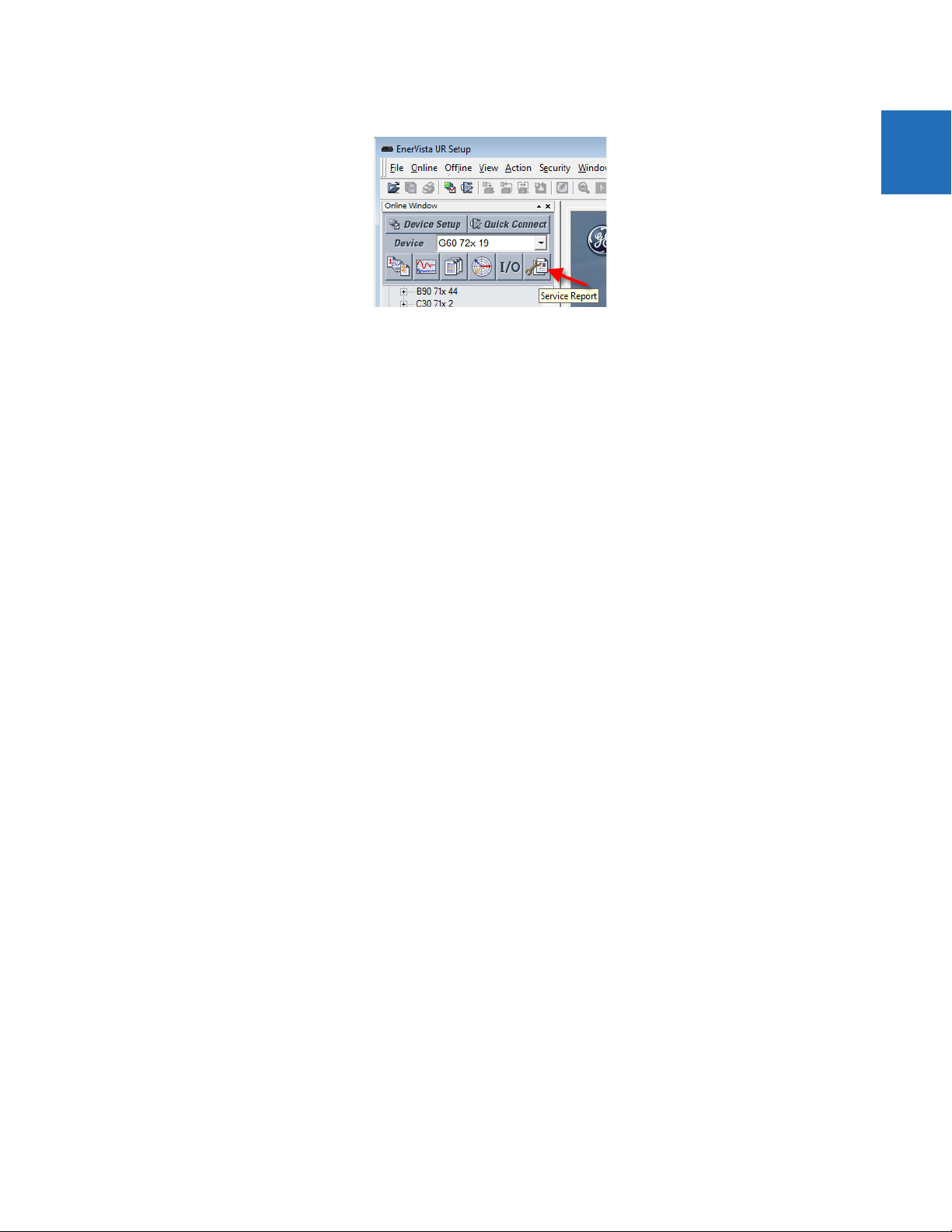
When contacting GE by e-mail, optionally include a device information file, which is generated in the EnerVista software by
clicking the Service Report button.
1-2 T60 TRANSFORMER PROTECTION SYSTEM – INSTRUCTION MANUAL
CHAPTER 1: INTRODUCTION FOR FURTHER ASSISTANCE
Figure 1-1: Generate service report
1
T60 TRANSFORMER PROTECTION SYSTEM – INSTRUCTION MANUAL 1-3

1
FOR FURTHER ASSISTANCE CHAPTER 1: INTRODUCTION
1-4 T60 TRANSFORMER PROTECTION SYSTEM – INSTRUCTION MANUAL

T60 Transformer Protection System
Chapter 2: Product description
Product description
This chapter outlines the product, order codes, and specifications.
2.1 Product description
The T60 Transformer Protection System is part of the Universal Relay (UR) series of products. It is a microprocessor-based
relay for protection of small, medium, and large three-phase power transformers. The relay can be configured for a
maximum of six three-phase current inputs and six ground current inputs, and can satisfy applications with transformer
windings connected between two breakers, such as in a ring bus or in breaker-and-a-half configurations. The T60
performs magnitude and phase shift compensation internally, eliminating requirements for external CT connections and
auxiliary CTs.
The percent differential element is the main protection device in the T60. Instantaneous differential protection, volts-perhertz, restricted ground fault, and many current, voltage, and frequency-based protection elements are also incorporated.
The T60 includes 16 programmable universal comparators, or FlexElements™, that provide additional flexibility by allowing
the user to customize their own protection functions that respond to any signals measured or calculated by the relay.
The metering functions of the T60 include true root mean square (RMS) and phasors for currents and voltages, current
harmonics and total harmonic distortion (THD), symmetrical components, frequency, power, power factor, and energy.
Diagnostic features include an event recorder capable of storing 1024 time-tagged events, oscillography capable of
storing up to 64 records with programmable trigger, content, and sampling rate, as well as data logger acquisition of up to
16 channels, with programmable content and sampling rate. The internal clock used for time-tagging can be synchronized
with an IRIG-B signal, using the Simple Network Time Protocol (SNTP) over the Ethernet port, or using the Precision Time
Protocol (PTP). This precise time stamping allows the sequence of events to be determined throughout the system. Events
can also be programmed (via FlexLogic™ equations) to trigger oscillography data capture that can be set to record the
measured parameters before and after the event for viewing on a computer. These tools significantly reduce
troubleshooting time and simplify report generation in the event of a system fault.
Several options are available for communication. A faceplate RS232 port can be used to connect to a computer to
program settings and monitor actual values. The rear RS485 port allows independent access by operating and engineering
staff. It can be connected to system computers with baud rates up to 115.2 kbps. All serial ports use the Modbus RTU
protocol. The IEC 60870-5-103 protocol is supported on the RS485 interface. IEC 60870-5-103, DNP, and Modbus cannot be
enabled simultaneously on this interface. Also only one of the DNP, IEC 60870-5-103, and IEC 60870-5-104 protocols can
be enabled at any time on the relay. When the IEC 60870-5-103 protocol is chosen, the RS485 port has a fixed even parity
and the baud rate can be either 9.6 kbps or 19.2 kbps. The 100Base-FX or 100Base-TX Ethernet interface provides fast,
reliable communications in noisy environments. The Ethernet port supports IEC 61850, IEC 61850-90-5, Modbus/TCP, TFTP,
and PTP (according to IEEE Std. 1588-2008 or IEC 61588), and it allows access to the relay via any standard web browser
(T60 web pages). The IEC 60870-5-104 protocol is supported on the Ethernet port. The Ethernet port also supports the
T60 TRANSFORMER PROTECTION SYSTEM – INSTRUCTION MANUAL 2-1

2
PRODUCT DESCRIPTION CHAPTER 2: PRODUCT DESCRIPTION
Parallel Redundancy Protocol (PRP) of IEC 62439-3 (clause 4, 2012) when purchased as an option.
Secure Routable GOOSE (R-GOOSE) is supported with software options.
Settings and actual values can be accessed from the front panel or EnerVista software.
The T60 uses flash memory technology that allows field upgrading as new features are added. Firmware and software are
upgradable.
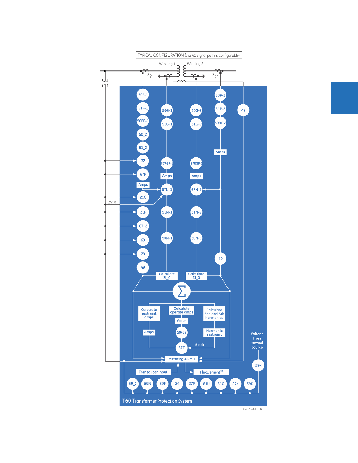
The following single-line diagram illustrates the relay functionality using American National Standards Institute (ANSI)
device numbers.
Table 2-1: ANSI device numbers and functions supported
Device
number
21G Ground distance 51P Phase time overcurrent
21P Phase distance 51_2 Negative-sequence time overcurrent
24 Volts per hertz 59N Neutral overvoltage
25 Synchrocheck 59P Phase overvoltage
27P Phase undervoltage 59X Auxiliary overvoltage
27X Auxiliary undervoltage 59_2 Negative-sequence overvoltage
32 Sensitive directional power 67N Neutral directional overcurrent
49 Thermal overload protection 67P Phase directional overcurrent
50/87 Instantaneous differential overcurrent 67_2 Negative-sequence directional overcurrent
50BF Breaker failure 68 Power swing blocking
50G Ground instantaneous overcurrent 78 Out-of-step tripping
50N Neutral instantaneous overcurrent 81O Overfrequency
50P Phase instantaneous overcurrent 81R Rate of change frequency
50_2 Negative-sequence instantaneous overcurrent 81U Underfrequency
51G Ground time overcurrent 87RGF Restricted ground fault
51N Neutral time overcurrent 87T Transformer differential
Function Device
number
Function
2-2 T60 TRANSFORMER PROTECTION SYSTEM – INSTRUCTION MANUAL
CHAPTER 2: PRODUCT DESCRIPTION PRODUCT DESCRIPTION
Figure 2-1: Single-line diagram
2
T60 TRANSFORMER PROTECTION SYSTEM – INSTRUCTION MANUAL 2-3
2
SECURITY CHAPTER 2: PRODUCT DESCRIPTION
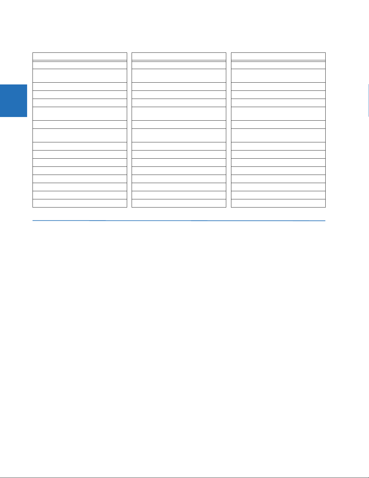
Table 2-2: Other device functions
FUNCTION FUNCTION FUNCTION
Breaker arcing current I
Breaker control FlexElements (16) Time synchronization over IRIG-B or IEEE
Breaker flashover FlexLogic equations Time synchronization over SNTP
Breaker restrike IEC 60870-5-103 communications Transducer inputs and outputs
Contact inputs (up to 96) IEC 61850 communications Transformer aging factor
Contact outputs (up to 64) IEC 62351-9 data and communications
Control pushbuttons Load encroachment Transformer loss-of-life
CT failure detector Metering: current, voltage, power, power
CyberSentry™ security Modbus communications User-definable displays
Data logger Modbus user map User-programmable fault reports
Digital counters (8) Non-volatile latches User-programmable LEDs
Digital elements (48) Non-volatile selector switch User-programmable pushbuttons
Direct inputs and outputs (32) Oscillography User-programmable self-tests
Disconnect switches Remote RTD inputs Virtual inputs (64)
DNP 3.0 or IEC 60870-5-104 protocol RTD inputs Virtual outputs (96)
Ethernet Global Data protocol Setting groups (6) VT fuse failure
2
t Event recorder Synchrophasor (PMU)
1588
security
factor, energy, frequency, harmonics, THD
Transformer hottest-spot temperature
Trip bus
2.2 Security
The following security features are available:
• Password security — Basic security present by default
• EnerVista security — Role-based access to various EnerVista software screens and configuration elements. The
feature is present by default in the EnerVista software.
• CyberSentry security — Advanced security available using a software option. When purchased, the option is
automatically enabled, and the default Password security and EnerVista security are disabled.
2.2.0.1 EnerVista security
The EnerVista security management system is a role-based access control (RBAC) system that allows an administrator to
manage the privileges of multiple users. This allows for access control of UR devices by multiple personnel within a
substation and conforms to the principles of RBAC as defined in ANSI INCITS 359-2004. The EnerVista security
management system is disabled by default to allow the administrator direct access to the EnerVista software after
installation. It is recommended that security be enabled before placing the device in service.
Basic password or enhanced CyberSentry security applies, depending on purchase.
2.2.0.2 Password security
Password security is a basic security feature present by default.
Two levels of password security are provided: command and setting. Use of a password for each level controls whether
users can enter commands and/or change settings.
The T60 supports password entry from a local or remote connection. Local access is defined as any access to settings or
commands via the faceplate interface. This includes both keypad entry and the through the faceplate RS232 port. Remote
access is defined as any access to settings or commands via any rear communications port. This includes both Ethernet
and RS485 connections. Any changes to the local or remote passwords enables this functionality.
2-4 T60 TRANSFORMER PROTECTION SYSTEM – INSTRUCTION MANUAL
CHAPTER 2: PRODUCT DESCRIPTION SECURITY
When entering a settings or command password via EnerVista or any serial interface, the user must enter the
corresponding connection password. If the connection is to the back of the T60, the remote password must be used. If the
connection is to the RS232 port of the faceplate, the local password applies.
Password access events are logged in the Event Recorder.
2.2.0.3 CyberSentry security
CyberSentry embedded security is available using a software option (Level 1) that provide advanced security services.
When the option is purchased, the basic password security is disabled automatically.
CyberSentry provides security through the following features:
• An Authentication, Authorization, Accounting (AAA) Remote Authentication Dial-In User Service (RADIUS) client that is
centrally managed, enables user attribution, provides accounting of all user activities, and uses secure standardsbased strong cryptography for authentication and credential protection
• A Role-Based Access Control (RBAC) system that provides a permission model that allows access to UR device
operations and configurations based on specific roles and individual user accounts configured on the AAA server (that
is, Administrator, Supervisor, Engineer, Operator, Observer roles)
• Security event reporting through the Syslog protocol for supporting Security Information Event Management (SIEM)
systems for centralized cybersecurity monitoring
• Strong encryption of all access and configuration network messages between the EnerVista software and UR devices
using the Secure Shell (SSH) protocol, the Advanced Encryption Standard (AES), and 128-bit keys in Galois Counter
Mode (GCM) as specified in the U.S. National Security Agency Suite B extension for SSH and approved by the National
Institute of Standards and Technology (NIST) FIPS-140-2 standards for cryptographic systems
2
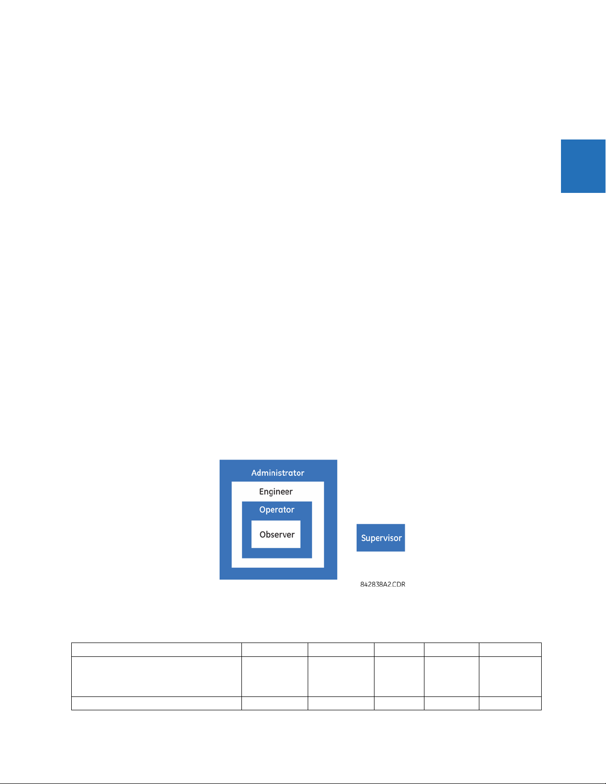
CyberSentry user roles
CyberSentry user roles (Administrator, Engineer, Operator, Supervisor, Observer) limit the levels of access to various UR
device functions. This means that the EnerVista software allows for access to functionality based on the user’s logged in
role.
Example: Administrative functions can be segmented away from common operator functions, or engineering type access,
all of which are defined by separate roles (see figure) so that access of UR devices by multiple personnel within a
substation is allowed.
Figure 2-2: CyberSentry user roles
The table lists user roles and their corresponding capabilities.
Table 2-3: Permissions by user role for CyberSentry
Roles Administrator Engineer Operator Supervisor Observer
Complete access Complete access
except for
CyberSentry
Security
Device Definition R R R R R
T60 TRANSFORMER PROTECTION SYSTEM – INSTRUCTION MANUAL 2-5
Command
menu
Authorizes
writing
Default role

2
SECURITY CHAPTER 2: PRODUCT DESCRIPTION
Roles Administrator Engineer Operator Supervisor Observer
Settings
|---------- Product Setup
|--------------- Security
(CyberSentry)
|--------------- Supervisory See table notes R R See table
|--------------- Display Properties RW RW R R R
|--------------- Clear Relay Records
(settings)
|--------------- Communications RW RW R R R
|--------------- Modbus User Map RW RW R R R
|--------------- Real Time Clock RW RW R R R
|--------------- Oscillography RW RW R R R
|--------------- Data Logger RW RW R R R
|--------------- Demand RW RW R R R
|--------------- User-Programmable
LEDs
|--------------- User-Programmable
Self Tests
|--------------- Control Pushbuttons RW RW R R R
|--------------- User-Programmable
Pushbuttons
|--------------- Flex state
Parameters
|--------------- User-Definable
Displays
|--------------- Direct I/O RW RW R R R
|--------------- Teleprotection RW RW R R R
|--------------- Installation RW RW R R R
|---------- System Setup RW RW R R R
|---------- FlexLogic RW RW R R R
|---------- Grouped Elements RW RW R R R
|---------- Control Elements RW RW R R R
|---------- Inputs / Outputs RW RW R R R
|--------------- Contact Inputs RW RW R R R
|--------------- Contact Input
threshold
|--------------- Virtual Inputs RW RW R R R
|--------------- Contact Outputs RW RW R R R
|--------------- Virtual Outputs RW RW R R R
|--------------- Resetting RW RW R R R
|--------------- Direct Inputs RW RW R R R
|--------------- Direct Outputs RW RW R R R
|--------------- Teleprotection RW RW R R R
|--------------- Direct Analogs RW RW R R R
|--------------- Direct Integers RW RW R R R
|---------- Transducer I/O RW RW R R R
|---------- Testing RW RW R R R
|---------- Front Panel Labels Designer NA NA NA NA NA
RW R R R R
R
notes
RW RW R R R
RW RW R R R
RW RW R R R
RW RW R R R
RW RW R R R
RW RW R R R
RW RW R R R
2-6 T60 TRANSFORMER PROTECTION SYSTEM – INSTRUCTION MANUAL

CHAPTER 2: PRODUCT DESCRIPTION SECURITY
Roles Administrator Engineer Operator Supervisor Observer
|---------- Protection Summary NA NA NA NA NA
Commands RW RW RW R R
|---------- Virtual Inputs RW RW RW R R
|---------- Clear Records RW RW RW R R
|---------- Set Date and Time RW RW RW R R
User Displays R R R R R
Targets R R R R R
Actual Values R R R R R
|---------- Front panel labels designer R R R R R
|---------- Status R R R R R
|---------- Metering R R R R R
|---------- Transducer I/O R R R R R
|---------- Records R R R R R
|---------- Product Info R R R R R
Maintenance RW RW R R R
|---------- Modbus Analyzer NA NA NA NA NA
|---------- Change front panel RW RW RW R R
|---------- Update firmware Yes No No No No
|---------- Retrieve file Yes No No No No
2
Table Notes:
RW = read and write access
R = read access
Supervisor = RW (default), Administrator = R (default), Administrator = RW (only if Supervisor role is disabled)
NA = the permission is not enforced by CyberSentry security
CyberSentry user authentication
The following types of authentication are supported by CyberSentry to access the UR device:
• Device Authentication (local UR device authenticates)
• Server Authentication (RADIUS server authenticates)
The EnerVista software allows access to functionality that is determined by the user role, which comes either from the local
UR device or the RADIUS server.
The EnerVista software has a device authentication option on the login screen for accessing the UR device. When the
"Device" button is selected, the UR uses its local authentication database and not the RADIUS server to authenticate the
user. In this case, it uses its built-in roles (Administrator, Engineer, Supervisor, Observer, Operator, or Administrator and
Supervisor when Device Authentication is disabled) as login names and the associated passwords are stored on the UR
device. As such, when using the local accounts, access is not user-attributable.
In cases where user-attributable access is required especially to facilitate auditable processes for compliance reasons, use
RADIUS authentication only.
When the "Server" Authentication Type option is selected, the UR uses the RADIUS server and not its local authentication
database to authenticate the user.
No password or security information is displayed in plain text by the EnerVista software or UR device, nor is such
information ever transmitted without cryptographic protection.
CyberSentry server authentication
The UR has been designed to direct automatically the authentication requests based on user names. In this respect, local
account names on the UR are considered as reserved and not used on a RADIUS server.
T60 TRANSFORMER PROTECTION SYSTEM – INSTRUCTION MANUAL 2-7

ORDER CODES CHAPTER 2: PRODUCT DESCRIPTION
The UR detects automatically whether an authentication request is to be handled remotely or locally. As there are five local
accounts possible on the UR, if the user ID credential does not match one of the five local accounts, the UR forwards
automatically the request to a RADIUS server when one is provided.
If a RADIUS server is provided, but is unreachable over the network, server authentication requests are denied. In this
situation, use local UR accounts to gain access to the UR system.
2
2.3 Order codes
The order code is on the product label and indicates the product options applicable.
The T60 is available as a 19-inch rack horizontal mount or reduced-size (¾) vertical unit. It consists of the following
modules: power supply, CPU, CT/VT, contact input and output, transducer input and output, and inter-relay
communications. Module options are specified at the time of ordering.
The order codes shown here are subject to change without notice. See the web page for the product for the latest options.
The order code depends on the mounting option (horizontal or vertical) and the type of CT/VT modules (enhanced
diagnostic CT/VT modules or HardFiber
HardFiber Bricks.
The R-GOOSE protocol described in IEC 61850-8-1 is available through the IEC 61850 software option. If R-GOOSE
security is required, the CyberSentry software option also must be purchased.
2.3.1 Order codes with enhanced CT/VT modules
The maximum number of Sources with three DSPs is four without the "six windings" software option and is six with
the "six windings" software option.
Table 2-4: T60 order codes for horizontal units
BASE UNIT T60 | | | | | | | | | | | Base Unit
CPU T | | | | | | | | | | RS485 and Three Multi-mode fiber 100Base-FX (SFP with LC)
SOFTWARE 00 | | | | | | | | | No Software Options
T60 - * ** - * * * - F ** - H ** - M ** - P ** - U ** - W/X ** Full Size Horizontal Mount
U | | | | | | | | | | RS485 and Two Multi-mode fiber 100Base-FX (SFP with LC), One 10/100Base-TX
V | | | | | | | | | | RS485 and Three 10/100Base-TX (SFP with RJ45)
01 | | | | | | | | | Ethernet Global Data (EGD);
03 | | | | | | | | | IEC 61850
04 | | | | | | | | | Ethernet Global Data (EGD) and IEC 61850
06 | | | | | | | | | Phasor Measurement Unit (PMU)
07 | | | | | | | | | IEC 61850 communications and Phasor Measurement Unit (PMU)
10 | | | | | | | | | Synchrocheck
11 | | | | | | | | | Synchrocheck and IEC 61850
20 | | | | | | | | | Six windings
21 | | | | | | | | | Six windings and Ethernet Global Data (EGD) protocol
22 | | | | | | | | | Six windings and IEC 61850 protocol
23 | | | | | | | | | Six windings, Ethernet Global Data (EGD) protocol, and IEC 61850 protocol
33 | | | | | | | | | Phasor Measurement Unit (PMU) and synchrocheck
34 | | | | | | | | | Phasor Measurement Unit (PMU), IEC 61850 protocol, and synchrocheck
A0 | | | | | | | | | CyberSentry Lvl 1
A1 | | | | | | | | | CyberSentry Lvl 1 and Ethernet Global Data (EGD)
A3 | | | | | | | | | CyberSentry Lvl 1 and IEC 61850
A4 | | | | | | | | | CyberSentry Lvl 1 and IEC 61850 and Ethernet Global Data (EGD)
A6 | | | | | | | | | CyberSentry Lvl 1 and Phasor Measurement Unit (PMU)
A7 | | | | | | | | | CyberSentry Lvl 1 and IEC 61850 and Phasor Measurement Unit (PMU)
AA | | | | | | | | | CyberSentry Lvl 1 and synchrocheck
AB | | | | | | | | | CyberSentry Lvl 1 and IEC 61850 and synchrocheck
AK | | | | | | | | | CyberSentry Lvl 1 and six windings
AL | | | | | | | | | CyberSentry Lvl 1 and Ethernet Global Data (EGD) and six windings
AM | | | | | | | | | CyberSentry Lvl 1 and IEC 61850 and six windings
AN | | | | | | | | | CyberSentry Lvl 1 and IEC 61850 and Ethernet Global Data (EGD) and six windings
AX | | | | | | | | | CyberSentry Lvl 1 and Phasor Measurement Unit (PMU) and synchrocheck
AY | | | | | | | | | CyberSentry Lvl 1 and IEC 61850 and Phasor Measurement Unit (PMU) and
B0 | | | | | | | | | IEEE 1588
B1 | | | | | | | | | IEEE 1588 and Ethernet Global Data (EGD)
B3 | | | | | | | | | IEEE 1588 and IEC 61850
B4 | | | | | | | | | IEEE 1588 and IEC 61850 and Ethernet Global Data (EGD)
B6 | | | | | | | | | IEEE 1588 and Phasor Measurement Unit (PMU)
B7 | | | | | | | | | IEEE 1588 and IEC 61850 and Phasor Measurement Unit (PMU)
BA | | | | | | | | | IEEE 1588 and synchrocheck
BB | | | | | | | | | IEEE 1588 and IEC 61850 and synchrocheck
BK | | | | | | | | | IEEE 1588 and six windings
BL | | | | | | | | | IEEE 1588 and Ethernet Global Data (EGD) and six windings
TM
process bus module). The process bus module provides an interface to
(SFP with RJ45)
synchrocheck
2-8 T60 TRANSFORMER PROTECTION SYSTEM – INSTRUCTION MANUAL

CHAPTER 2: PRODUCT DESCRIPTION ORDER CODES
BASE UNIT T60 | | | | | | | | | | | Base Unit
T60 - * ** - * * * - F ** - H ** - M ** - P ** - U ** - W/X ** Full Size Horizontal Mount
BM | | | | | | | | | IEEE 1588 and IEC 61850 and six windings
BN | | | | | | | | | IEEE 1588 and IEC 61850 and Ethernet Global Data (EGD) and six windings
BX | | | | | | | | | IEEE 1588 and Phasor Measurement Unit (PMU) and synchrocheck
BY | | | | | | | | | IEEE 1588 and IEC 61850 and Phasor Measurement Unit (PMU) and synchrocheck
C0 | | | | | | | | | Parallel Redundancy Protocol (PRP)
C1 | | | | | | | | | PRP and Ethernet Global Data (EGD)
C3 | | | | | | | | | PRP and IEC 61850
C4 | | | | | | | | | PRP, Ethernet Global Data (EGD), and IEC 61850
C6 | | | | | | | | | PRP and PMU
C7 | | | | | | | | | PRP, IEC 61850, and PMU
CA | | | | | | | | | PRP and Synchrocheck
CB | | | | | | | | | PRP, IEC 61850, and Synchrocheck
CK | | | | | | | | | PRP and six windings
CL | | | | | | | | | PRP, six windings, and Ethernet Global Data
CM | | | | | | | | | PRP, six windings, and IEC 61850
CN | | | | | | | | | PRP, six windings, Ethernet Global Data, and IEC 61850
CX | | | | | | | | | PRP, PMU, and Synchrocheck
CY | | | | | | | | | PRP, PMU, IEC 61850, and Synchrocheck
D0 | | | | | | | | | IEEE 1588 and CyberSentry Lvl 1
D1 | | | | | | | | | IEEE 1588 and CyberSentry Lvl 1 and Ethernet Global Data (EGD)
D3 | | | | | | | | | IEEE 1588 and CyberSentry Lvl 1 and IEC 61850
D4 | | | | | | | | | IEEE 1588 and CyberSentry Lvl 1 and IEC 61850 and Ethernet Global Data (EGD)
D6 | | | | | | | | | IEEE 1588 and CyberSentry Lvl 1 and Phasor Measurement Unit (PMU)
D7 | | | | | | | | | IEEE 1588 and CyberSentry Lvl 1 and IEC 61850 and Phasor Measurement Unit
DA | | | | | | | | | IEEE 1588 and CyberSentry Lvl 1 and synchrocheck
DB | | | | | | | | | IEEE 1588 and CyberSentry Lvl 1 IEC 61850 and synchrocheck
DK | | | | | | | | | IEEE 1588 and CyberSentry Lvl 1 and six windings
DL | | | | | | | | | IEEE 1588 and CyberSentry Lvl 1 and Ethernet Global Data (EGD) and six windings
DM | | | | | | | | | IEEE 1588 and CyberSentry Lvl 1 and IEC 61850 and six windings
DN | | | | | | | | | IEEE 1588 and CyberSentry Lvl 1 and IEC 61850 and Ethernet Global Data (EGD)
DX | | | | | | | | | IEEE 1588 and CyberSentry Lvl 1 and Phasor Measurement Unit (PMU) and
DY | | | | | | | | | IEEE 1588 and CyberSentry Lvl 1 and IEC 61850 and Phasor Measurement Unit
E0 | | | | | | | | | IEEE 1588 and PRP
E1 | | | | | | | | | IEEE 1588, PRP, and Ethernet Global Dada
E3 | | | | | | | | | IEEE 1588, PRP, and IEC 61850
E4 | | | | | | | | | IEEE 1588, PRP, Ethernet Global Data, and IEC 61850
E6 | | | | | | | | | IEEE 1588, PRP, and PMU
E7 | | | | | | | | | IEEE 1588, PRP, IEC 61850, and PMU
EA | | | | | | | | | IEEE 1588, PRP, and Synchrocheck
EB | | | | | | | | | IEEE 1588, PRP, IEC 61850, and Synchrocheck
EK | | | | | | | | | IEEE 1588, PRP, and six windings
EL | | | | | | | | | IEEE 1588, PRP, six windings, and Ethernet Global Data
EM | | | | | | | | | IEEE 1588, PRP, six windings, and IEC 61850
EN | | | | | | | | | IEEE 1588, PRP, six windings, Ethernet Global Data, and IEC 61850
EX | | | | | | | | | IEEE 1588, PRP, PMU, and Synchrocheck
EY | | | | | | | | | IEEE 1588, PRP, PMU, IEC 61850, and Synchrocheck
F0 | | | | | | | | | PRP and CyberSentry Lvl1
F1 | | | | | | | | | PRP, CyberSentry Lvl1, and Ethernet Global Data
F3 | | | | | | | | | PRP, CyberSentry Lvl 1, and IEC 61850
F4 | | | | | | | | | PRP, CyberSentry Lvl 1, Ethernet Global Data, and IEC 61850
F6 | | | | | | | | | PRP, CyberSentry Lvl 1, and PMU
F7 | | | | | | | | | PRP, CyberSentry Lvl 1, IEC 61850, and PMU
FA | | | | | | | | | PRP, CyberSentry Lvl 1, and Synchrocheck
FB | | | | | | | | | PRP, CyberSentry Lvl 1, IEC 61850, and Synchrocheck
FK | | | | | | | | | PRP, CyberSentry Lvl 1, and six windings
FL | | | | | | | | | PRP, CyberSentry Lvl 1, six windings, and Ethernet Global Data
FM | | | | | | | | | PRP, CyberSentry Lvl 1, six windings, and IEC 61850
FN | | | | | | | | | PRP, CyberSentry Lvl 1, six windings, Ethernet Global Data, and IEC 61850
FX | | | | | | | | | PRP, CyberSentry Lvl 1, PMU, and Synchrocheck
FY | | | | | | | | | PRP, CyberSentry Lvl 1, PMU, IEC 61850, and Synchrocheck
G0 | | | | | | | | | IEEE 1588, PRP, and CyberSentry Lvl 1
G1 | | | | | | | | | IEEE 1588, PRP, CyberSentry Lvl 1, Ethernet Global Data
G3 | | | | | | | | | IEEE 1588, PRP, CyberSentry Lvl 1, and IEC 61850
G4 | | | | | | | | | IEEE 1588, PRP, CyberSentry Lvl 1, Ethernet Global Data, and IEC 61850
G6 | | | | | | | | | IEEE 1588, PRP, CyberSentry Lvl 1, and PMU
G7 | | | | | | | | | IEEE 1588, PRP, CyberSentry Lvl 1, IEC 61850, and PMU
GA | | | | | | | | | IEEE 1588, PRP, CyberSentry Lvl 1, and Synchrocheck
GB | | | | | | | | | IEEE 1588, PRP, CyberSentry Lvl 1, IEC 61850, and Synchrocheck
GK | | | | | | | | | IEEE 1588, PRP, CyberSentry Lvl 1, and six windings
GL | | | | | | | | | IEEE 1588, PRP, CyberSentry Lvl 1, six windings, and Ethernet Global Data
GM | | | | | | | | | IEEE 1588, PRP, CyberSentry Lvl 1, six windings, and IEC 61850
GN | | | | | | | | | IEEE 1588, PRP, CyberSentry Lvl 1, six windings, Ethernet Global Data, and IEC
GX | | | | | | | | | IEEE 1588, PRP, CyberSentry Lvl 1, PMU, and Synchrocheck
GY | | | | | | | | | IEEE 1588, PRP, CyberSentry Lvl 1, PMU, IEC 61850, and Synchrocheck
J0 | | | | | | | | | IEC 60870-5-103
J1 | | | | | | | | | IEC 60870-5-103 + EGD
J3 | | | | | | | | | IEC 60870-5-103 + IEC 61850
J4 | | | | | | | | | IEC 60870-5-103 + EGD + IEC 61850
J6 | | | | | | | | | IEC 60870-5-103 + PMU
J7 | | | | | | | | | IEC 60870-5-103 + IEC 61850 + PMU
JA | | | | | | | | | IEC 60870-5-103 + Synchrocheck
JB | | | | | | | | | IEC 60870-5-103 + IEC 61850 + Synchrocheck
JK | | | | | | | | | IEC 60870-5-103 + six windings
JL | | | | | | | | | IEC 60870-5-103 + six windings + EGD
JM | | | | | | | | | IEC 60870-5-103 + six windings + IEC 61850
JN | | | | | | | | | IEC 60870-5-103 + six windings + EGD + IEC 61850
JX | | | | | | | | | IEC 60870-5-103 + PMU + Synchrocheck
JY | | | | | | | | | IEC 60870-5-103 + PMU + IEC 61850 + Synchrocheck
K0 | | | | | | | | | IEEE1588 + PRP + IEC 60870-5-103
K1 | | | | | | | | | IEEE1588 + PRP + IEC 60870-5-103 + EGD
K3 | | | | | | | | | IEEE1588 + PRP + IEC 60870-5-103 + IEC 61850
K4 | | | | | | | | | IEEE1588 + PRP + IEC 60870-5-103 + EGD + IEC 61850
K6 | | | | | | | | | IEEE1588 + PRP + IEC 60870-5-103 + PMU
K7 | | | | | | | | | IEEE1588 + PRP + IEC 60870-5-103 + IEC 61850 + PMU
KA | | | | | | | | | IEEE1588 + PRP + IEC 60870-5-103 + Synchrocheck
KB | | | | | | | | | IEEE1588 + PRP + IEC 60870-5-103 + IEC 61850 + Synchrocheck
(PMU)
and six windings
synchrocheck
(PMU) and synchrocheck
61850
2
T60 TRANSFORMER PROTECTION SYSTEM – INSTRUCTION MANUAL 2-9

ORDER CODES CHAPTER 2: PRODUCT DESCRIPTION
2
BASE UNIT T60 | | | | | | | | | | | Base Unit
MOUNT/COATING H | | | | | | | | Horizontal (19” rack)
FACEPLATE/DISPLAY C | | | | | | | English display
T60 - * ** - * * * - F ** - H ** - M ** - P ** - U ** - W/X ** Full Size Horizontal Mount
KK | | | | | | | | | IEEE1588 + PRP + IEC 60870-5-103 + six windings
KL | | | | | | | | | IEEE1588 + PRP + IEC 60870-5-103 + six windings + EGD
KM | | | | | | | | | IEEE1588 + PRP + IEC 60870-5-103 + six windings + IEC 61850
KN | | | | | | | | | IEEE1588 + PRP + IEC 60870-5-103 + six windings + EGD + IEC 61850
KX | | | | | | | | | IEEE1588 + PRP + IEC 60870-5-103 + PMU + Synchrocheck
KY | | | | | | | | | IEEE1588 + PRP + IEC 60870-5-103 + PMU + IEC 61850 + Synchrocheck
L0 | | | | | | | | | IEC 60870-5-103 + IEEE 1588 + PRP + CyberSentry Lvl 1
L1 | | | | | | | | | IEC 60870-5-103 + IEEE 1588 + PRP + CyberSentry Lvl 1 + EGD
L3 | | | | | | | | | IEC 60870-5-103 + IEEE 1588 + PRP + CyberSentry Lvl 1 + IEC 61850
L4 | | | | | | | | | IEC 60870-5-103 + IEEE 1588 + PRP + CyberSentry Lvl 1 + EGD + IEC 61850
L6 | | | | | | | | | IEC 60870-5-103 + IEEE 1588 + PRP + CyberSentry Lvl 1 + PMU
L7 | | | | | | | | | IEC 60870-5-103 + IEEE 1588 + PRP + CyberSentry Lvl 1 + IEC 61850 + PMU
LA | | | | | | | | | IEC 60870-5-103 + IEEE 1588 + PRP + CyberSentry Lvl 1 + Synchrocheck
LB | | | | | | | | | IEC 60870-5-103 + IEEE 1588 + PRP + CyberSentry Lvl 1 + IEC 61850 +
LK | | | | | | | | | IEC 60870-5-103 + IEEE 1588 + PRP + CyberSentry Lvl 1 + six windings
LL | | | | | | | | | IEC 60870-5-103 + IEEE 1588 + PRP + CyberSentry Lvl 1 + six windings + EGD
LM | | | | | | | | | IEC 60870-5-103 + IEEE 1588 + PRP + CyberSentry Lvl 1 + six windings + IEC 61850
LN | | | | | | | | | IEC 60870-5-103 + IEEE 1588 + PRP + CyberSentry Lvl 1 + six windings + EG D + IEC
LX | | | | | | | | | IEC 60870-5-103 + IEEE 1588 + PRP + CyberSentry Lvl 1 + PMU + Synchrocheck
LY | | | | | | | | | IEC 60870-5-103 + IEEE 1588 + PRP + CyberSentry Lvl 1 + PMU + IEC 61850 +
M0 | | | | | | | | | IEC 61850 + PMU + 61850-90-5
M5 | | | | | | | | | PMU + IEC 61850 + Synchrocheck + 61850-90-5
M7 | | | | | | | | | CyberSentry UR Lvl 1 + IEC 61850 + PMU + 61850-90-5
MC | | | | | | | | | CyberSentry UR Lvl 1 + PMU + IEC 61850 + Synchrocheck + 61850-90-5
MD | | | | | | | | | IEEE 1588 + IEC 61850 + PMU + 61850-90-5
MI | | | | | | | | | IEEE 1588 + PMU + IEC 61850 + Synchrocheck + 61850-90-5
MJ | | | | | | | | | PRP + IEC 61850 + PMU + 61850-90-5
MO | | | | | | | | | PRP + PMU + IEC 61850 + Synchrocheck + 61850-90-5
MP | | | | | | | | | IEEE 1588 + CyberSentry UR Lvl 1 + IEC 61850 + PMU + 61850-90-5
MU | | | | | | | | | IEEE 1588 + CyberSentry UR Lvl 1 + PMU + IEC 61850 + Synchrocheck + 61850-90-
MV | | | | | | | | | IEEE 1588 + PRP + IEC 61850 + PMU + 61850-90-5
N0 | | | | | | | | | IEEE 1588 + PRP + PMU + IEC 61850 + Synchrocheck + 61850-90-5
N1 | | | | | | | | | PRP + CyberSentry UR Lvl 1 + IEC 61850 + PMU + 61850-90-5
N6 | | | | | | | | | PRP + CyberSentry UR Lvl 1 + PMU + IEC 61850 + Synchrocheck + 61850-90-5
N7 | | | | | | | | | IEEE 1588 + PRP + CyberSentry UR Lvl 1 + IEC 61850 + PMU + 61850-90-5
NC | | | | | | | | | IEEE 1588 + PRP + CyberSentry UR Lvl 1 + PMU + IEC 61850 + Synchrocheck +
ND | | | | | | | | | IEC 60870-5-103 + IEC 61850 + PMU + 61850-90-5
NI | | | | | | | | | IEC 60870-5-103 + PMU + IEC 61850 + Synchrocheck + 61850-90-5
NJ | | | | | | | | | IEEE 1588 + PRP + IEC 60870-5-103 + IEC 61850 + PMU + 61850-90-5
NO | | | | | | | | | IEEE 1588 + PRP + IEC 60870-5-103 + PMU + IEC 61850 + Synchrocheck + 61850-
NP | | | | | | | | | IEC 60870-5-103 + IEEE 1588 + PRP + CyberSentry UR Lvl 1 + IEC 61850 + PMU +
NU | | | | | | | | | IEC 60870-5-103 + IEEE 1588 + PRP + CyberSentry UR Lvl 1 + PMU + IEC 61850 +
A | | | | | | | | Horizontal (19” rack) with harsh environmental coating
D | | | | | | | French display
R | | | | | | | Russian display
A | | | | | | | Chinese display
P | | | | | | | English display with 4 small and 12 large programmable pushbuttons
G | | | | | | | French display with 4 small and 12 large programmable pushbuttons
S | | | | | | | Russian display with 4 small and 12 large programmable pushbuttons
B | | | | | | | Chinese display with 4 small and 12 large programmable pushbuttons
K | | | | | | | Enhanced front panel with English display
M | | | | | | | Enhanced front panel with French display
Q | | | | | | | Enhanced front panel with Russian display
U | | | | | | | Enhanced front panel with Chinese display
L | | | | | | | Enhanced front panel with English display and user-programmable pushbuttons
N | | | | | | | Enhanced front panel with French display and user-programmable pushbuttons
T | | | | | | | Enhanced front panel with Russian display and user-programmable pushbuttons
V | | | | | | | Enhanced front panel with Chinese display and user-programmable pushbuttons
W | | | | | | | Enhan ced front panel with Turkish display
Y | | | | | | | Enhanced front panel with Turkish display and user-programmable pushbuttons
I | | | | | | | Enhan ced front panel with German display
J | | | | | | | Enh anced front panel with German display and user-programmable pushbuttons
Synchrocheck
61850
Synchrocheck
5
61850-90-5
90-5
61850-90-5
Synchrocheck + 61850-90-5
2-10 T60 TRANSFORMER PROTECTION SYSTEM – INSTRUCTION MANUAL

CHAPTER 2: PRODUCT DESCRIPTION ORDER CODES
BASE UNIT T60 | | | | | | | | | | | Base Unit
POWER SUPPLY
(redundant supply must be same
type as main supply)
ENHANCED DIAGNOSTICS CT/VT DSP
(requires all DSP to be enhanced
diagnostic)
CONTACT INPUTS/OUTPUTS XX XX XX XX XX No Module
TRANSDUCER
INPUTS/OUTPUTS
(select a maximum of 3 per unit)
INTER-RELAY
COMMUNICATIONS
(select a maximum of 1 per unit)
T60 - * ** - * * * - F ** - H ** - M ** - P ** - U ** - W/X ** Full Size Horizontal Mount
H | | | | | | 125 / 250 V AC/DC power supply
H | | | | | SH 125 / 250 V AC/DC with redundant 125 / 250 V AC/DC power supply
L | | | | | | 24 to 48 V (DC only) power supply
L | | | | | SL 24 to 48 V (DC only) with redundant 24 to 48 V DC power supply
| | XX | XX | No DSP module (slots M and U only)
8L | 8L | 8L | Standard 4CT/4VT with enhanced diagnostics
8M | 8M | 8M | Sensitive Ground 4CT/4VT with enhanced diagnostics
8N | 8N | 8N | Standard 8CT with enhanced diagnostics
8R | 8R | 8R | Sensitive Ground 8CT with enhanced diagnostics
4A 4A 4A 4A 4A 4 Solid-State (no monitoring) MOSFET outputs
4B 4B 4B 4B 4B 4 Solid-State (voltage with optional current) MOSFET outputs
4C 4C 4C 4C 4C 4 Solid-State (current with optional voltage) MOSFET outputs
4D 4D 4D 4D 4D 16 Contact inputs with Auto-Burnishing (maximum of three modules within a
4L 4L 4L 4L 4L 14 Form-A (no monitoring) Latching outputs
67 67 67 67 67 8 Form-A (no monitoring) outputs
6A 6A 6A 6A 6A 2 Form-A (voltage with optional current) and 2 Form-C outputs, 8 contact inputs
6B 6B 6B 6B 6B 2 Form-A (voltage with optional current) and 4 Form-C outputs, 4 contact inputs
6C 6C 6C 6C 6C 8 Form-C outputs
6D 6D 6D 6D 6D 16 Contact inputs
6E 6E 6E 6E 6E 4 Form-C outputs, 8 contact inputs
6F 6F 6F 6F 6F 8 Fast Form-C outputs
6G 6G 6G 6G 6G 4 Form-A (voltage with optional current) outputs, 8 contact inputs
6H 6H 6H 6H 6H 6 Form-A (voltage with optional current) outputs, 4 contact inputs
6K 6K 6K 6K 6K 4 Form-C and 4 Fast Form-C outputs
6L 6L 6L 6L 6L 2 Form-A (current with optional voltage) and 2 Form-C outputs, 8 contact inputs
6M 6M 6M 6M 6M 2 Form-A (current with optional voltage) and 4 Form-C outputs, 4 contact inputs
6N 6N 6N 6N 6N 4 Form-A (current with optional voltage) outputs, 8 contact inputs
6P 6P 6P 6P 6P 6 Form-A (current with optional voltage) outputs, 4 contact inputs
6R 6R 6R 6R 6R 2 Form-A (no monitoring) and 2 Form-C outputs, 8 contact inputs
6S 6S 6S 6S 6S 2 Form-A (no monitoring) and 4 Form-C outputs, 4 contact inputs
6T 6T 6T 6T 6T 4 Form-A (no monitoring) outputs, 8 contact inputs
6U 6U 6U 6U 6U 6 Form-A (no monitoring) outputs, 4 contact inputs
6V 6V 6V 6V 6V 2 Form-A outputs, 1 Form-C output , 2 Form-A (no monitoring) latching outputs, 8
5A 5A 5A 5A 5A 4 DCmA inputs, 4 DCmA outputs (only one 5A module is allowed)
5C 5C 5C 5C 5C 8 RTD inputs
5D 5D 5D 5D 5D 4 RTD inputs, 4 DCmA outputs (only one 5D module is allowed)
5E 5E 5E 5E 5E 4 RTD inputs, 4 DCmA inputs
5F 5F 5F 5F 5F 8 DCmA inputs
case)
contact inputs
2A C37.94SM, 1300 nm single-mode, ELED, 1 channel single-mode
2B C37.94SM, 1300 nm single-mode, ELED, 2 channel single-mode
2E Bi-phase, single channel
2F Bi-phase, dual channel
2G IEEE C37.94, 820 nm, 128 kbps, multimode, LED, 1 Channel
2H IEEE C37.94, 820 nm, 128 kbps, multimode, LED, 2 Channels
2I Channel 1 - IEEE C37.94, MM, 64/128 kbps; Channel 2 - 1300 nm, single-mode,
Laser
2J Channel 1 - IEEE C37.94, MM, 64/128 kbps; Channel 2 - 1550 nm, single-mode,
Laser
72 1550 nm, single-mode, Laser, 1 Channel
73 1550 nm, single-mode, Laser, 2 Channel
74 Channel 1 - RS422; Channel 2 - 1550 nm, single-mode, Laser
75 Channel 1 - G.703; Channel 2 - 1550 nm, single-mode Laser
76 IEEE C37.94, 820 nm, 64 kbps, multimode, LED, 1 Channel
77 IEEE C37.94, 820 nm, 64 kbps, multimode, LED, 2 Channels
7A 820 nm, multimode, LED, 1 Channel
7B 1300 nm, multimode, LED, 1 Channel
7C 1300 nm, single-mode, ELED, 1 Channel
7D 1300 nm, single-mode, Laser, 1 Channel
7E Channel 1 - G.703; Channel 2 - 820 nm, multimode
7F Channel 1 - G.703; Channel 2 - 1300 nm, multimode
7G Channel 1 - G.703; Channel 2 - 1300 nm, single-mode ELED
7H 820 nm, multimode, LED, 2 Channels
7I 1300 nm, multimode, LED, 2 Channels
7J 1300 nm, single-mode, ELED, 2 Channels
7K 1300 nm, single-mode, Laser, 2 Channels
7L Channel 1 - RS422; Channel 2 - 820 nm, multimode, LED
7M Channel 1 - RS422; Channel 2 - 1300 nm, multimode, LED
7N Channel 1 - RS422; Channel 2 - 1300 nm, single-mode, ELED
7P Channel 1 - RS422; Channel 2 - 1300 nm, single-mode, Laser
7Q Channel 1 - G.703; Channel 2 - 1300 nm, single-mode Laser
7R G.703, 1 Channel
7S G.703, 2 Channels
7T RS422, 1 Channel
7W RS422, 2 Channels
2
Table 2-5: T60 order codes for reduced-size vertical units
BASE UNIT T60 | | | | | | | | | Base Unit
CPU T | | | | | | | | RS485 and Three Multi-mode fiber 100Base-FX (SFP with LC)
SOFTWARE 00 | | | | | | | No Software Options
T60 TRANSFORMER PROTECTION SYSTEM – INSTRUCTION MANUAL 2-11
T60 - * ** - * * * - F ** - H ** - M ** - P/R ** Reduced Size Vertical Mount (see note regarding P/R slot below)
U | | | | | | | | RS485 and Two Multi-mode fiber 100Base-FX (SFP with LC), One 10/100Base-TX (SFP with RJ45)
V | | | | | | | | RS485 and Three 10/100Base-TX (SFP with RJ45)
01 | | | | | | | Ethernet Global Data (EGD)
03 | | | | | | | IEC 61850
04 | | | | | | | Ethernet Global Data (EGD) and IEC 61850
06 | | | | | | | Phasor Measurement Unit (PMU)
07 | | | | | | | IEC 61850 communications and Phasor Measurement Unit (PMU)

ORDER CODES CHAPTER 2: PRODUCT DESCRIPTION
2
T60 - * ** - * * * - F ** - H ** - M ** - P/R ** Reduced Size Vertical Mount (see note regarding P/R slot below)
10 | | | | | | | Synchrocheck
11 | | | | | | | Synchrocheck and IEC 61850
20 | | | | | | | Six windings with breaker failure
21 | | | | | | | Six windings with breaker failure and Ethernet Global Data (EGD) protocol
22 | | | | | | | Six windings with breaker failure and IEC 61850 protocol
23 | | | | | | | Six windings with breaker failure, Ethernet Global Data (EGD) protocol, and IEC 61850 protocol
33 | | | | | | | Phasor Measurement Unit (PMU) and synchrocheck
34 | | | | | | | Phasor Measurement Unit (PMU), IEC 61850 protocol, and synchrocheck
A0 | | | | | | | CyberSentry Lvl 1
A1 | | | | | | | CyberSentry Lvl 1 and Ethernet Global Data (EGD)
A3 | | | | | | | CyberSentry Lvl 1 and IEC 61850
A4 | | | | | | | CyberSentry Lvl 1 and IEC 61850 and Ethernet Global Data (EGD)
A6 | | | | | | | CyberSentry Lvl 1 and Phasor Measurement Unit (PMU)
A7 | | | | | | | CyberSentry Lvl 1 and IEC 61850 and Phasor Measurement Unit (PMU)
AA | | | | | | | CyberSentry Lvl 1 and synchrocheck
AB | | | | | | | CyberSentry Lvl 1 and IEC 61850 and synchrocheck
AK | | | | | | | CyberSentry Lvl 1 and six windings
AL | | | | | | | CyberSentry Lvl 1 and Ethernet Global Data (EGD) and six windings
AM | | | | | | | CyberSentry Lvl 1 and IEC 61850 and six windings
AN | | | | | | | CyberSentry Lvl 1 and IEC 61850 and Ethernet Global Data (EGD) and six windings
AX | | | | | | | CyberSentry Lvl 1 and Phasor Measurement Unit (PMU) and synchrocheck
AY | | | | | | | CyberSentry Lvl 1 and IEC 61850 and Phasor Measurement Unit (PMU) and synchrocheck
B0 | | | | | | | IEEE 1588
B1 | | | | | | | IEEE 1588 and Ethernet Global Data (EGD)
B3 | | | | | | | IEEE 1588 and IEC 61850
B4 | | | | | | | IEEE 1588 and IEC 61850 and Ethernet Global Data (EGD)
B6 | | | | | | | IEEE 1588 and Phasor Measurement Unit (PMU)
B7 | | | | | | | IEEE 1588 and IEC 61850 and Phasor Measurement Unit (PMU)
BA | | | | | | | IEEE 1588 and synchrocheck
BB | | | | | | | IEEE 1588 and IEC 61850 and synchrocheck
BK | | | | | | | IEEE 1588 and six windings
BL | | | | | | | IEEE 1588 and Ethernet Global Data (EGD) and six windings
BM | | | | | | | IEEE 1588 and IEC 61850 and six windings
BN | | | | | | | IEEE 1588 and IEC 61850 and Ethernet Global Data (EGD) and six windings
BX | | | | | | | IEEE 1588 and Phasor Measurement Unit (PMU) and synchrocheck
BY | | | | | | | IEEE 1588 and IEC 61850 and Phasor Measurement Unit (PMU) and synchrocheck
C0 | | | | | | | PRP and CyberSentry Lvl1
C1 | | | | | | | PRP, CyberSentry Lvl1, and Ethernet Global Data
C3 | | | | | | | PRP, CyberSentry Lvl 1, and IEC 61850
C4 | | | | | | | PRP, CyberSentry Lvl 1, Ethernet Global Data, and IEC 61850
C6 | | | | | | | PRP, CyberSentry Lvl 1, and PMU
C7 | | | | | | | PRP, CyberSentry Lvl 1, IEC 61850, and PMU
CA | | | | | | | PRP, CyberSentry Lvl 1, and Synchrocheck
CB | | | | | | | PRP, CyberSentry Lvl 1, IEC 61850, and Synchrocheck
CK | | | | | | | PRP, CyberSentry Lvl 1, and six windings
CL | | | | | | | PRP, CyberSentry Lvl 1, six windings, and Ethernet Global Data
CM | | | | | | | PRP, CyberSentry Lvl 1, six windings, and IEC 61850
CN | | | | | | | PRP, CyberSentry Lvl 1, six windings, Ethernet Global Data, and IEC 61850
CX | | | | | | | PRP, CyberSentry Lvl 1, PMU, and Synchrocheck
CY | | | | | | | PRP, CyberSentry Lvl 1, PMU, IEC 61850, and Synchrocheck
D0 | | | | | | | IEEE 1588 and CyberSentry Lvl 1
D1 | | | | | | | IEEE 1588 and CyberSentry Lvl 1 and Ethernet Global Data (EGD)
D3 | | | | | | | IEEE 1588 and CyberSentry Lvl 1 and IEC 61850
D4 | | | | | | | IEEE 1588 and CyberSentry Lvl 1 and IEC 61850 and Ethernet Global Data (EGD)
D6 | | | | | | | IEEE 1588 and CyberSentry Lvl 1 and Phasor Measurement Unit (PMU)
D7 | | | | | | | IEEE 1588 and CyberSentry Lvl 1 and IEC 61850 and Phasor Measurement Unit (PMU)
DA | | | | | | | IEEE 1588 and CyberSentry Lvl 1 and synchrocheck
DB | | | | | | | IEEE 1588 and CyberSentry Lvl 1 IEC 61850 and synchrocheck
DK | | | | | | | IEEE 1588 and CyberSentry Lvl 1 and six windings
DL | | | | | | | IEEE 1588 and CyberSentry Lvl 1 and Ethernet Global Data (EGD) and six windings
DM | | | | | | | IEEE 1588 and CyberSentry Lvl 1 and IEC 61850 and six windings
DN | | | | | | | IEEE 1588 and CyberSentry Lvl 1 and IEC 61850 and Ethernet Global Data (EGD) and six windings
DX | | | | | | | IEEE 1588 and CyberSentry Lvl 1 and Phasor Measurement Unit (PMU) and synchrocheck
DY | | | | | | | IEEE 1588 and CyberSentry Lvl 1 and IEC 61850 and Phasor Measurement Unit (PMU) and synchrocheck
E0 | | | | | | | IEEE 1588 and PRP
E1 | | | | | | | IEEE 1588, PRP, and Ethernet Global Dada
E3 | | | | | | | IEEE 1588, PRP, and IEC 61850
E4 | | | | | | | IEEE 1588, PRP, Ethernet Global Data, and IEC 61850
E6 | | | | | | | IEEE 1588, PRP, and PMU
E7 | | | | | | | IEEE 1588, PRP, IEC 61850, and PMU
EA | | | | | | | IEEE 1588, PRP, and Synchrocheck
EB | | | | | | | IEEE 1588, PRP, IEC 61850, and Synchrocheck
EK | | | | | | | IEEE 1588, PRP, and six windings
EL | | | | | | | IEEE 1588, PRP, six windings, and Ethernet Global Data
EM | | | | | | | IEEE 1588, PRP, six windings, and IEC 61850
EN | | | | | | | IEEE 1588, PRP, six windings, Ethernet Global Data, and IEC 61850
EX | | | | | | | IEEE 1588, PRP, PMU, and Synchrocheck
EY | | | | | | | IEEE 1588, PRP, PMU, IEC 61850, and Synchrocheck
F0 | | | | | | | PRP and CyberSentry Lvl1
F1 | | | | | | | PRP, CyberSentry Lvl1, and Ethernet Global Data
F3 | | | | | | | PRP, CyberSentry Lvl 1, and IEC 61850
F4 | | | | | | | PRP, CyberSentry Lvl 1, Ethernet Global Data, and IEC 61850
F6 | | | | | | | PRP, CyberSentry Lvl 1, and PMU
F7 | | | | | | | PRP, CyberSentry Lvl 1, IEC 61850, and PMU
FA | | | | | | | PRP, CyberSentry Lvl 1, and Synchrocheck
FB | | | | | | | PRP, CyberSentry Lvl 1, IEC 61850, and Synchrocheck
FK | | | | | | | PRP, CyberSentry Lvl 1, and six windings
FL | | | | | | | PRP, CyberSentry Lvl 1, six windings, and Ethernet Global Data
FM | | | | | | | PRP, CyberSentry Lvl 1, six windings, and IEC 61850
FN | | | | | | | PRP, CyberSentry Lvl 1, six windings, Ethernet Global Data, and IEC 61850
FX | | | | | | | PRP, CyberSentry Lvl 1, PMU, and Synchrocheck
FY | | | | | | | PRP, CyberSentry Lvl 1, PMU, IEC 61850, and Synchrocheck
G0 | | | | | | | IEEE 1588, PRP, and CyberSentry Lvl 1
G1 | | | | | | | IEEE 1588, PRP, CyberSentry Lvl 1, Ethernet Global Data
G3 | | | | | | | IEEE 1588, PRP, CyberSentry Lvl 1, and IEC 61850
G4 | | | | | | | IEEE 1588, PRP, CyberSentry Lvl 1, Ethernet Global Data, and IEC 61850
G6 | | | | | | | IEEE 1588, PRP, CyberSentry Lvl 1, and PMU
G7 | | | | | | | IEEE 1588, PRP, CyberSentry Lvl 1, IEC 61850, and PMU
GA | | | | | | | IEEE 1588, PRP, CyberSentry Lvl 1, and Synchrocheck
GB | | | | | | | IEEE 1588, PRP, CyberSentry Lvl 1, IEC 61850, and Synchrocheck
GK | | | | | | | IEEE 1588, PRP, CyberSentry Lvl 1, and six windings
GL | | | | | | | IEEE 1588, PRP, CyberSentry Lvl 1, six windings, and Ethernet Global Data
GM | | | | | | | IEEE 1588, PRP, CyberSentry Lvl 1, six windings, and IEC 61850
2-12 T60 TRANSFORMER PROTECTION SYSTEM – INSTRUCTION MANUAL

CHAPTER 2: PRODUCT DESCRIPTION ORDER CODES
T60 - * ** - * * * - F ** - H ** - M ** - P/R ** Reduced Size Vertical Mount (see note regarding P/R slot below)
MOUNT/COATING V | | | | | | Vertical (3/4 rack)
FACEPLATE/DISPLAY F | | | | | English display
GN | | | | | | | IEEE 1588, PRP, CyberSentry Lvl 1, six windings, Ethernet Global Data, and IEC 61850
GX | | | | | | | IEEE 1588, PRP, CyberSentry Lvl 1, PMU, and Synchrocheck
GY | | | | | | | IEEE 1588, PRP, CyberSentry Lvl 1, PMU, IEC 61850, and Synchrocheck
J0 | | | | | | | IEC 60870-5-103
J1 | | | | | | | IEC 60870-5-103 + EGD
J3 | | | | | | | IEC 60870-5-103 + IEC 61850
J4 | | | | | | | IEC 60870-5-103 + EGD + IEC 61850
J6 | | | | | | | IEC 60870-5-103 + PMU
J7 | | | | | | | IEC 60870-5-103 + IEC 61850 + PMU
JA | | | | | | | IEC 60870-5-103 + Synchrocheck
JB | | | | | | | IEC 60870-5-103 + IEC 61850 + Synchrocheck
JK | | | | | | | IEC 60870-5-103 + six windings
JL | | | | | | | IEC 60870-5-103 + six windings + EGD
JM | | | | | | | IEC 60870-5-103 + six windings + IEC 61850
JN | | | | | | | IEC 60870-5-103 + six windings + EGD + IEC 61850
JX | | | | | | | IEC 60870-5-103 + PMU + Synchrocheck
JY | | | | | | | IEC 60870-5-103 + PMU + IEC 61850 + Synchrocheck
K0 | | | | | | | IEEE1588 + PRP + IEC 60870-5-103
K1 | | | | | | | IEEE1588 + PRP + IEC 60870-5-103 + EGD
K3 | | | | | | | IEEE1588 + PRP + IEC 60870-5-103 + IEC 61850
K4 | | | | | | | IEEE1588 + PRP + IEC 60870-5-103 + EGD + IEC 61850
K6 | | | | | | | IEEE1588 + PRP + IEC 60870-5-103 + PMU
K7 | | | | | | | IEEE1588 + PRP + IEC 60870-5-103 + IEC 61850 + PMU
KA | | | | | | | IEEE1588 + PRP + IEC 60870-5-103 + Synchrocheck
KB | | | | | | | IEEE1588 + PRP + IEC 60870-5-103 + IEC 61850 + Synchrocheck
KK | | | | | | | IEEE1588 + PRP + IEC 60870-5-103 + six windings
KL | | | | | | | IEEE1588 + PRP + IEC 60870-5-103 + six wind ings + EGD
KM | | | | | | | IEEE1588 + PRP + IEC 60870-5-103 + six windings + IEC 61850
KN | | | | | | | IEEE1588 + PRP + IEC 60870-5-103 + six windings + EGD + IEC 61850
KX | | | | | | | IEEE1588 + PRP + IEC 60870-5-103 + PMU + Synchrocheck
KY | | | | | | | IEEE1588 + PRP + IEC 60870-5-103 + PMU + IEC 61850 + Synchrocheck
L0 | | | | | | | IEC 60870-5-103 + IEEE 1588 + PRP + CyberSentry Lvl 1
L1 | | | | | | | IEC 60870-5-103 + IEEE 1588 + PRP + CyberSentry Lvl 1 + EGD
L3 | | | | | | | IEC 60870-5-103 + IEEE 1588 + PRP + CyberSentry Lvl 1 + IEC 61850
L4 | | | | | | | IEC 60870-5-103 + IEEE 1588 + PRP + CyberSentry Lvl 1 + EGD + IEC 61850
L6 | | | | | | | IEC 60870-5-103 + IEEE 1588 + PRP + CyberSentry Lvl 1 + PMU
L7 | | | | | | | IEC 60870-5-103 + IEEE 1588 + PRP + CyberSentry Lvl 1 + IEC 61850 + PMU
LA | | | | | | | IEC 60870-5-103 + IEEE 1588 + PRP + CyberSentry Lvl 1 + Synchrocheck
LB | | | | | | | IEC 60870-5-103 + IEEE 1588 + PRP + CyberSentry Lvl 1 + IEC 61850 + Synchrocheck
LK | | | | | | | IEC 60870-5-103 + IEEE 1588 + PRP + CyberSentry Lvl 1 + six windings
LL | | | | | | | IEC 60870-5-103 + IEEE 1588 + PRP + CyberSentry Lvl 1 + six windings + EGD
LM | | | | | | | IEC 60870-5-103 + IEEE 1588 + PRP + CyberSentry Lvl 1 + six windings + IEC 61850
LN | | | | | | | IEC 60870-5-103 + IEEE 1588 + PRP + CyberSentry Lvl 1 + six windings + EGD + IEC 61850
LX | | | | | | | IEC 60870-5-103 + IEEE 1588 + PRP + CyberSentry Lvl 1 + PMU + Synchrocheck
LY | | | | | | | IEC 60870-5-103 + IEEE 1588 + PRP + CyberSentry Lvl 1 + PMU + IEC 61850 + Synchrocheck
M0 | | | | | | | IEC 61850 + PMU + 61850-90-5
M5 | | | | | | | PMU + IEC 61850 + Synchrocheck + 61850-90-5
M7 | | | | | | | CyberSentry UR Lvl 1 + IEC 61850 + PMU + 61850-90-5
MC | | | | | | | CyberSentry UR Lvl 1 + PMU + IEC 61850 + Synchrocheck + 61850-90-5
MD | | | | | | | IEEE 1588 + IEC 61850 + PMU + 61850-90-5
MI | | | | | | | IEEE 1588 + PMU + IEC 61850 + Synchrocheck + 61850-90-5
MJ | | | | | | | PRP + IEC 61850 + PMU + 61850-90-5
MO | | | | | | | PRP + PMU + IEC 61850 + Synchrocheck + 61850-90-5
MP | | | | | | | IEEE 1588 + CyberSentry UR Lvl 1 + IEC 61850 + PMU + 61850-90-5
MU | | | | | | | IEEE 1588 + CyberSentry UR Lvl 1 + PMU + IEC 61850 + Synchrocheck + 61850-90-5
MV | | | | | | | IEEE 1588 + PRP + IEC 61850 + PMU + 61850-90-5
N0 | | | | | | | IEEE 1588 + PRP + PMU + IEC 61850 + Synchrocheck + 61850-90-5
N1 | | | | | | | PRP + CyberSentry UR Lvl 1 + IEC 61850 + PMU + 61850-90-5
N6 | | | | | | | PRP + CyberSentry UR Lvl 1 + PMU + IEC 61850 + Synchrocheck + 61850-90-5
N7 | | | | | | | IEEE 1588 + PRP + CyberSentry UR Lvl 1 + IEC 61850 + PMU + 61850-90-5
NC | | | | | | | IEEE 1588 + PRP + CyberSentry UR Lvl 1 + PMU + IEC 61850 + Synchrocheck + 61850-90-5
ND | | | | | | | IEC 60870-5-103 + IEC 61850 + PMU + 61850-90-5
NI | | | | | | | IEC 60870-5-103 + PMU + IEC 61850 + Synchrocheck + 61850-90-5
NJ | | | | | | | IEEE 1588 + PRP + IEC 60870-5-103 + IEC 61850 + PMU + 61850-90-5
NO | | | | | | | IEEE 1588 + PRP + IEC 60870-5-103 + PMU + IEC 61850 + Synchrocheck + 61850-90-5
NP | | | | | | | IEC 60870-5-103 + IEEE 1588 + PRP + CyberSentry UR Lvl 1 + IEC 61850 + PMU + 61850-90-5
NU | | | | | | | IEC 60870-5-103 + IEEE 1588 + PRP + CyberSentry UR Lvl 1 + PMU + IEC 61850 + Synchrocheck + 61850-
B | | | | | | Vertical (3/4 rack) with harsh environmental coating
D | | | | | French display
R | | | | | Russian display
A | | | | | Chinese display
K | | | | | Enhanced front panel with English display
M | | | | | Enhanced front panel with French display
Q | | | | | Enhanced front panel with Russian display
U | | | | | Enhanced front panel with Chinese display
L | | | | | Enhanced front panel with English display and user-programmable pushbutt ons
N | | | | | Enhanced front panel with French display and user-programmable pushbuttons
T | | | | | Enhanced front panel with Russian display and user-programmable pushbuttons
V | | | | | Enhanced front panel with Chinese display and user-programmable pushbuttons
W | | | | | Enhanced front panel with Turkish display
Y | | | | | Enhanced front panel with Turkish display and user-programmable pushbuttons
I | | | | | Enhanced front panel with German display
J | | | | | Enhanced front panel with German d isplay and user-programmable pushbuttons
90-5
2
T60 TRANSFORMER PROTECTION SYSTEM – INSTRUCTION MANUAL 2-13

ORDER CODES CHAPTER 2: PRODUCT DESCRIPTION
2
POWER SUPPLY H | | | | 125 / 250 V AC/DC power supply
ENHANCED DIAGNOSTICS CT/VT
DSP
(requires all DSP to be enhanced
diagnostic)
CONTACT INPUTS/OUTPUTS XX XX XX No Module
TRANSDUCER
INPUTS/OUTPUTS
(select a maximum of 3 per unit)
INTER-RELAY
COMMUNICATIONS
(select a maximum of 1 per unit)
T60 - * ** - * * * - F ** - H ** - M ** - P/R ** Reduced Size Vertical Mount (see note regarding P/R slot below)
L | | | | 24 to 48 V (DC only) power supply
XX | XX | No DSP module (slots M and U only)
8L | 8L | Standard 4CT/4VT with enhanced diagnostics
8M | 8M | Sensitive Ground 4CT/4VT with enhanced diagnostics
8N | 8N | Standard 8CT with enhanced diagnostics
8R | 8R | Sensitive Ground 8CT with enhanced diagnostics
4A 4A 4A 4 Solid-State (no monitoring) MOSFET outputs
4B 4B 4B 4 Solid-State (voltage with optional current) MOSFET outputs
4C 4C 4C 4 Solid-State (current with optional voltage) MOSFET outputs
4D 4D 4D 16 Contact inputs with Auto-Burnishing (maximum of three modules within a case)
4L 4L 4L 14 Form-A (no monitoring) Latching outputs
67 67 67 8 Form-A (no monitoring) outputs
6A 6A 6A 2 Form-A (voltage with optional current) and 2 Form-C outputs, 8 contact inputs
6B 6B 6B 2 Form-A (voltage with optional current) and 4 Form-C outputs, 4 contact inputs
6C 6C 6C 8 Form-C outputs
6D 6D 6D 16 Contact inputs
6E 6E 6E 4 Form-C outputs, 8 contact inputs
6F 6F 6F 8 Fast Form-C outputs
6G 6G 6G 4 Form-A (voltage with optional current) outputs, 8 contact inputs
6H 6H 6H 6 Form-A (voltage with optional current) outputs, 4 contact inputs
6K 6K 6K 4 Form-C and 4 Fast Form-C outputs
6L 6L 6L 2 Form-A (current with optional voltage) and 2 Form-C outputs, 8 contact inputs
6M 6M 6M 2 Form-A (current with optional voltage) and 4 Form-C outputs, 4 contact inputs
6N 6N 6N 4 Form-A (current with optional voltage) outputs, 8 contact inputs
6P 6P 6P 6 Form-A (current with optional voltage) outputs, 4 contact inputs
6R 6R 6R 2 Form-A (no monit oring) and 2 Form-C outputs, 8 contact inputs
6S 6S 6S 2 Form-A (no monitoring) and 4 Form-C outputs, 4 contact inputs
6T 6T 6T 4 Form-A (no monitoring) outputs, 8 contact inputs
6U 6U 6U 6 Form-A (no monitoring) outputs, 4 contact inputs
6V 6V 6V 2 Form-A outputs, 1 Form-C output , 2 Form-A (no monitoring) latching outputs, 8 contact inputs
5A 5A 5A 4 DCmA inputs, 4 DCmA outputs (only one 5A module is allowed)
5C 5C 5C 8 RTD inputs
5D 5D 5D 4 RTD inputs, 4 DCmA outputs (only one 5D module is allowed)
5E 5E 5E 4 RTD inputs, 4 DCmA inputs
5F 5F 5F 8 DCmA inputs
2A C37.94SM, 1300 nm single-mode, ELED, 1 channel single-mode
2B C37.94SM, 1300 nm single-mode, ELED, 2 channel single-mode
2E Bi-phase, single channel
2F Bi-phase, dual channel
2G IEEE C37.94, 820 nm, 128 kbps, multimode, LED, 1 Channel
2H IEEE C37.94, 820 nm, 128 kbps, multimode, LED, 2 Channels
2I Channel 1 - IEEE C37.94, MM, 64/128 kbps; Channel 2 - 1300 nm, single-mode, Laser
2J Channel 1 - IEEE C37.94, MM, 64/128 kbps; Channel 2 - 1550 nm, single-mode, Laser
72 1550 nm, single-mode, Laser, 1 Channel
73 1550 nm, single-mode, Laser, 2 Channel
74 Channel 1 - RS422; Channel 2 - 1550 nm, single-mode, Laser
75 Channel 1 - G.703; Channel 2 - 1550 nm, Single-mode Laser
76 IEEE C37.94, 820 nm, 64 kbps, multimode, LED, 1 Channel
77 IEEE C37.94, 820 nm, 64 kbps, multimode, LED, 2 Channels
7A 820 nm, multimode, LED, 1 Channel
7B 1300 nm, multimode, LED, 1 Channel
7C 1300 nm, single-mode, ELED, 1 Channel
7D 1300 nm, single-mode, Laser, 1 Channel
7E Channel 1 - G.703; Channel 2 - 820 nm, multimode
7F Channel 1 - G.703; Channel 2 - 1300 nm, multimode
7G Channel 1 - G.703; Channel 2 - 1300 nm, single-mode ELED
7H 820 nm, multimode, LED, 2 Channels
7I 1300 nm, multimode, LED, 2 Channels
7J 1300 nm, single-mode, ELED, 2 Channels
7K 1300 nm, single-mode, Laser, 2 Channels
7L Channel 1 - RS422; Channel 2 - 820 nm, multimode, LED
7M Channel 1 - RS422; Channel 2 - 1300 nm, multimode, LED
7N Channel 1 - RS422; Channel 2 - 1300 nm, single-mode, ELED
7P Channel 1 - RS422; Channel 2 - 1300 nm, single-mode, Laser
7Q Channel 1 - G.703; Channel 2 - 1300 nm, single-mode Laser
7R G.703, 1 Channel
7S G.703, 2 Channels
7T RS422, 1 Channel
7W RS422, 2 Channels
2.3.2 Order codes with process bus modules
Table 2-6: T60 order codes for horizontal units with process bus
BASE UNIT T60 | | | | | | | | | | | Base Unit
CPU T | | | | | | | | | | RS485 and Three Multi-mode fiber 100Base-FX (SFP with LC)
SOFTWARE 00 | | | | | | | | | No Software Options
2-14 T60 TRANSFORMER PROTECTION SYSTEM – INSTRUCTION MANUAL
T60 - * ** - * * * - F ** - H ** - M ** - P ** - U ** - W/X ** Full Size Horizontal Mount
U | | | | | | | | | | RS485 and Two Multi-mode fiber 100Base-FX (SFP with LC), One 10/100Base-TX
V | | | | | | | | | | RS485 and Three 10/100Base-TX (SFP with RJ45)
01 | | | | | | | | | Ethernet Global Data (EGD)
03 | | | | | | | | | IEC 61850
04 | | | | | | | | | Ethernet Global Data (EGD) and IEC 61850
06 | | | | | | | | | Phasor Measurement Unit (PMU)
07 | | | | | | | | | IEC 61850 communications and Phasor Measurement Unit (PMU)
10 | | | | | | | | | Synchrocheck
11 | | | | | | | | | Synchrocheck and IEC 61850
20 | | | | | | | | | Six windings
21 | | | | | | | | | Six windings and Ethernet Global Data (EGD) protocol
22 | | | | | | | | | Six windings and IEC 61850 protocol
23 | | | | | | | | | Six windings, Ethernet Global Data (EGD) protocol, and IEC 61850 protocol
33 | | | | | | | | | Phasor Measurement Unit (PMU) and synchrocheck
34 | | | | | | | | | Phasor Measurement Unit (PMU), IEC 61850 protocol, and synchrocheck
A0 | | | | | | | | | CyberSentry Lvl 1
A1 | | | | | | | | | CyberSentry Lvl 1 and Ethernet Global Data (EGD)
A3 | | | | | | | | | CyberSentry Lvl 1 and IEC 61850
(SFP with RJ45)

CHAPTER 2: PRODUCT DESCRIPTION ORDER CODES
BASE UNIT T60 | | | | | | | | | | | Base Unit
T60 - * ** - * * * - F ** - H ** - M ** - P ** - U ** - W/X ** Full Size Horizontal Mount
A4 | | | | | | | | | CyberSentry Lvl 1 and IEC 61850 and Ethernet Global Data (EGD)
A6 | | | | | | | | | CyberSentry Lvl 1 and Phasor Measurement Unit (PMU)
A7 | | | | | | | | | CyberSentry Lvl 1 and IEC 61850 and Phasor Measurement Unit (PMU)
AA | | | | | | | | | CyberSentry Lvl 1 and synchrocheck
AB | | | | | | | | | CyberSentry Lvl 1 and IEC 61850 and synchrocheck
AK | | | | | | | | | CyberSentry Lvl 1 and six windings
AL | | | | | | | | | CyberSentry Lvl 1 and Ethernet Global Data (EGD) and six windings
AM | | | | | | | | | CyberSentry Lvl 1 and IEC 61850 and six windings
AN | | | | | | | | | CyberSentry Lvl 1 and IEC 61850 and Ethernet Global Data (EGD) and six windings
AX | | | | | | | | | CyberSentry Lvl 1 and Phasor Measurement Unit (PMU) and synchrocheck
AY | | | | | | | | | CyberSentry Lvl 1 and IEC 61850 and Phasor Measurement Unit (PMU) and
B0 | | | | | | | | | IEEE 1588
B1 | | | | | | | | | IEEE 1588 and Ethernet Global Data (EGD)
B3 | | | | | | | | | IEEE 1588 and IEC 61850
B4 | | | | | | | | | IEEE 1588 and IEC 61850 and Ethernet Global Data (EGD)
B6 | | | | | | | | | IEEE 1588 and Phasor Measurement Unit (PMU)
B7 | | | | | | | | | IEEE 1588 and IEC 61850 and Phasor Measurement Unit (PMU)
BA | | | | | | | | | IEEE 1588 and synchrocheck
BB | | | | | | | | | IEEE 1588 and IEC 61850 and synchrocheck
BK | | | | | | | | | IEEE 1588 and six windings
BL | | | | | | | | | IEEE 1588 and Ethernet Global Data (EGD) and six windings
BM | | | | | | | | | IEEE 1588 and IEC 61850 and six windings
BN | | | | | | | | | IEEE 1588 and IEC 61850 and Ethernet Global Data (EGD) and six windings
BX | | | | | | | | | IEEE 1588 and Phasor Measurement Unit (PMU) and synchrocheck
BY | | | | | | | | | IEEE 1588 and IEC 61850 and Phasor Measurement Unit (PMU) and synchrocheck
C0 | | | | | | | | | Parallel Redundancy Protocol (PRP)
C1 | | | | | | | | | PRP and Ethernet Global Data (EGD)
C3 | | | | | | | | | PRP and IEC 61850
C4 | | | | | | | | | PRP, Ethernet Global Data (EGD), and IEC 61850
C6 | | | | | | | | | PRP and PMU
C7 | | | | | | | | | PRP, IEC 61850, and PMU
CA | | | | | | | | | PRP and Synchrocheck
CB | | | | | | | | | PRP, IEC 61850, and Synchrocheck
CK | | | | | | | | | PRP and six windings
CL | | | | | | | | | PRP, six windings, and Ethernet Global Data
CM | | | | | | | | | PRP, six windings, and IEC 61850
CN | | | | | | | | | PRP, six windings, Ethernet Global Data, and IEC 61850
CX | | | | | | | | | PRP, PMU, and Synchrocheck
CY | | | | | | | | | PRP, PMU, IEC 61850, and Synchrocheck
D0 | | | | | | | | | IEEE 1588 and CyberSentry Lvl 1
D1 | | | | | | | | | IEEE 1588 and CyberSentry Lvl 1 and Ethernet Global Data (EGD)
D3 | | | | | | | | | IEEE 1588 and CyberSentry Lvl 1 and IEC 61850
D4 | | | | | | | | | IEEE 1588 and CyberSentry Lvl 1 and IEC 61850 and Ethernet Global Data (EGD)
D6 | | | | | | | | | IEEE 1588 and CyberSentry Lvl 1 and Phasor Measurement Unit (PMU)
D7 | | | | | | | | | IEEE 1588 and CyberSentry Lvl 1 and IEC 61850 and Phasor Measurement Unit
DA | | | | | | | | | IEEE 1588 and CyberSentry Lvl 1 and synchrocheck
DB | | | | | | | | | IEEE 1588 and CyberSentry Lvl 1 IEC 61850 and synchrocheck
DK | | | | | | | | | IEEE 1588 and CyberSentry Lvl 1 and six windings
DL | | | | | | | | | IEEE 1588 and CyberSentry Lvl 1 and Ethernet Global Data (EGD) and six windings
DM | | | | | | | | | IEEE 1588 and CyberSentry Lvl 1 and IEC 61850 and six windings
DN | | | | | | | | | IEEE 1588 and CyberSentry Lvl 1 and IEC 61850 and Ethernet Global Data (EGD)
DX | | | | | | | | | IEEE 1588 and CyberSentry Lvl 1 and Phasor Measurement Unit (PMU) and
DY | | | | | | | | | IEEE 1588 and CyberSentry Lvl 1 and IEC 61850 and Phasor Measurement Unit
E0 | | | | | | | | | IEEE 1588 and PRP
E1 | | | | | | | | | IEEE 1588, PRP, and Ethernet Global Dada
E3 | | | | | | | | | IEEE 1588, PRP, and IEC 61850
E4 | | | | | | | | | IEEE 1588, PRP, Ethernet Global Data, and IEC 61850
E6 | | | | | | | | | IEEE 1588, PRP, and PMU
E7 | | | | | | | | | IEEE 1588, PRP, IEC 61850, and PMU
EA | | | | | | | | | IEEE 1588, PRP, and Synchrocheck
EB | | | | | | | | | IEEE 1588, PRP, IEC 61850, and Synchrocheck
EK | | | | | | | | | IEEE 1588, PRP, and six windings
EL | | | | | | | | | IEEE 1588, PRP, six windings, and Ethernet Global Data
EM | | | | | | | | | IEEE 1588, PRP, six windings, and IEC 61850
EN | | | | | | | | | IEEE 1588, PRP, six windings, Ethernet Global Data, and IEC 61850
EX | | | | | | | | | IEEE 1588, PRP, PMU, and Synchrocheck
EY | | | | | | | | | IEEE 1588, PRP, PMU, IEC 61850, and Synchrocheck
F0 | | | | | | | | | PRP and CyberSentry Lvl1
F1 | | | | | | | | | PRP, CyberSentry Lvl1, and Ethernet Global Data
F3 | | | | | | | | | PRP, CyberSentry Lvl 1, and IEC 61850
F4 | | | | | | | | | PRP, CyberSentry Lvl 1, Ethernet Global Data, and IEC 61850
F6 | | | | | | | | | PRP, CyberSentry Lvl 1, and PMU
F7 | | | | | | | | | PRP, CyberSentry Lvl 1, IEC 61850, and PMU
FA | | | | | | | | | PRP, CyberSentry Lvl 1, and Synchrocheck
FB | | | | | | | | | PRP, CyberSentry Lvl 1, IEC 61850, and Synchrocheck
FK | | | | | | | | | PRP, CyberSentry Lvl 1, and six windings
FL | | | | | | | | | PRP, CyberSentry Lvl 1, six windings, and Ethernet Global Data
FM | | | | | | | | | PRP, CyberSentry Lvl 1, six windings, and IEC 61850
FN | | | | | | | | | PRP, CyberSentry Lvl 1, six windings, Ethernet Global Data, and IEC 61850
FX | | | | | | | | | PRP, CyberSentry Lvl 1, PMU, and Synchrocheck
FY | | | | | | | | | PRP, CyberSentry Lvl 1, PMU, IEC 61850, and Synchrocheck
G0 | | | | | | | | | IEEE 1588, PRP, and CyberSentry Lvl 1
G1 | | | | | | | | | IEEE 1588, PRP, CyberSentry Lvl 1, Ethernet Global Data
G3 | | | | | | | | | IEEE 1588, PRP, CyberSentry Lvl 1, and IEC 61850
G4 | | | | | | | | | IEEE 1588, PRP, CyberSentry Lvl 1, Ethernet Global Data, and IEC 61850
G6 | | | | | | | | | IEEE 1588, PRP, CyberSentry Lvl 1, and PMU
G7 | | | | | | | | | IEEE 1588, PRP, CyberSentry Lvl 1, IEC 61850, and PMU
GA | | | | | | | | | IEEE 1588, PRP, CyberSentry Lvl 1, and Synchrocheck
GB | | | | | | | | | IEEE 1588, PRP, CyberSentry Lvl 1, IEC 61850, and Synchrocheck
GK | | | | | | | | | IEEE 1588, PRP, CyberSentry Lvl 1, and six windings
GL | | | | | | | | | IEEE 1588, PRP, CyberSentry Lvl 1, six windings, and Ethernet Global Data
GM | | | | | | | | | IEEE 1588, PRP, CyberSentry Lvl 1, six windings, and IEC 61850
GN | | | | | | | | | IEEE 1588, PRP, CyberSentry Lvl 1, six windings, Ethernet Global Data, and IEC
GX | | | | | | | | | IEEE 1588, PRP, CyberSentry Lvl 1, PMU, and Synchrocheck
GY | | | | | | | | | IEEE 1588, PRP, CyberSentry Lvl 1, PMU, IEC 61850, and Synchrocheck
synchrocheck
(PMU)
and six windings
synchrocheck
(PMU) and synchrocheck
61850
2
T60 TRANSFORMER PROTECTION SYSTEM – INSTRUCTION MANUAL 2-15

ORDER CODES CHAPTER 2: PRODUCT DESCRIPTION
2
BASE UNIT T60 | | | | | | | | | | | Base Unit
MOUNT/COATING H | | | | | | | | Horizontal (19” rack)
FACEPLATE/ DISPLAY C | | | | | | | English display
T60 - * ** - * * * - F ** - H ** - M ** - P ** - U ** - W/X ** Full Size Horizontal Mount
J0 | | | | | | | | | IEC 60870-5-103
J1 | | | | | | | | | IEC 60870-5-103 + EGD
J3 | | | | | | | | | IEC 60870-5-103 + IEC 61850
J4 | | | | | | | | | IEC 60870-5-103 + EGD + IEC 61850
J6 | | | | | | | | | IEC 60870-5-103 + PMU
J7 | | | | | | | | | IEC 60870-5-103 + IEC 61850 + PMU
JA | | | | | | | | | IEC 60870-5-103 + Synchrocheck
JB | | | | | | | | | IEC 60870-5-103 + IEC 61850 + Synchrocheck
JK | | | | | | | | | IEC 60870-5-103 + six windings
JL | | | | | | | | | IEC 60870-5-103 + six windings + EGD
JM | | | | | | | | | IEC 60870-5-103 + six windings + IEC 61850
JN | | | | | | | | | IEC 60870-5-103 + six windings + EGD + IEC 61850
JX | | | | | | | | | IEC 60870-5-103 + PMU + Synchrocheck
JY | | | | | | | | | IEC 60870-5-103 + PMU + IEC 61850 + Synchrocheck
K0 | | | | | | | | | IEEE1588 + PRP + IEC 60870-5-103
K1 | | | | | | | | | IEEE1588 + PRP + IEC 60870-5-103 + EGD
K3 | | | | | | | | | IEEE1588 + PRP + IEC 60870-5-103 + IEC 61850
K4 | | | | | | | | | IEEE1588 + PRP + IEC 60870-5-103 + EGD + IEC 61850
K6 | | | | | | | | | IEEE1588 + PRP + IEC 60870-5-103 + PMU
K7 | | | | | | | | | IEEE1588 + PRP + IEC 60870-5-103 + IEC 61850 + PMU
KA | | | | | | | | | IEEE1588 + PRP + IEC 60870-5-103 + Synchrocheck
KB | | | | | | | | | IEEE1588 + PRP + IEC 60870-5-103 + IEC 61850 + Synchrocheck
KK | | | | | | | | | IEEE1588 + PRP + IEC 60870-5-103 + six windings
KL | | | | | | | | | IEEE1588 + PRP + IEC 60870-5-103 + six windings + EGD
KM | | | | | | | | | IEEE1588 + PRP + IEC 60870-5-103 + six windings + IEC 61850
KN | | | | | | | | | IEEE1588 + PRP + IEC 60870-5-103 + six windings + EGD + IEC 61850
KX | | | | | | | | | IEEE1588 + PRP + IEC 60870-5-103 + PMU + Synchrocheck
KY | | | | | | | | | IEEE1588 + PRP + IEC 60870-5-103 + PMU + IEC 61850 + Synchrocheck
L0 | | | | | | | | | IEC 60870-5-103 + IEEE 1588 + PRP + CyberSentry Lvl 1
L1 | | | | | | | | | IEC 60870-5-103 + IEEE 1588 + PRP + CyberSentry Lvl 1 + EGD
L3 | | | | | | | | | IEC 60870-5-103 + IEEE 1588 + PRP + CyberSentry Lvl 1 + IEC 61850
L4 | | | | | | | | | IEC 60870-5-103 + IEEE 1588 + PRP + CyberSentry Lvl 1 + EGD + IEC 61850
L6 | | | | | | | | | IEC 60870-5-103 + IEEE 1588 + PRP + CyberSentry Lvl 1 + PMU
L7 | | | | | | | | | IEC 60870-5-103 + IEEE 1588 + PRP + CyberSentry Lvl 1 + IEC 61850 + PMU
LA | | | | | | | | | IEC 60870-5-103 + IEEE 1588 + PRP + CyberSentry Lvl 1 + Synchrocheck
LB | | | | | | | | | IEC 60870-5-103 + IEEE 1588 + PRP + CyberSentry Lvl 1 + IEC 61850 +
LK | | | | | | | | | IEC 60870-5-103 + IEEE 1588 + PRP + CyberSentry Lvl 1 + six windings
LL | | | | | | | | | IEC 60870-5-103 + IEEE 1588 + PRP + CyberSentry Lvl 1 + six windings + EGD
LM | | | | | | | | | IEC 60870-5-103 + IEEE 1588 + PRP + CyberSentry Lvl 1 + six windings + IEC 61850
LN | | | | | | | | | IEC 60870-5-103 + IEEE 1588 + PRP + CyberSentry Lvl 1 + six windings + EG D + IEC
LX | | | | | | | | | IEC 60870-5-103 + IEEE 1588 + PRP + CyberSentry Lvl 1 + PMU + Synchrocheck
LY | | | | | | | | | IEC 60870-5-103 + IEEE 1588 + PRP + CyberSentry Lvl 1 + PMU + IEC 61850 +
M0 | | | | | | | | | IEC 61850 + PMU + 61850-90-5
M5 | | | | | | | | | PMU + IEC 61850 + Synchrocheck + 61850-90-5
M7 | | | | | | | | | CyberSentry UR Lvl 1 + IEC 61850 + PMU + 61850-90-5
MC | | | | | | | | | CyberSentry UR Lvl 1 + PMU + IEC 61850 + Synchrocheck + 61850-90-5
MD | | | | | | | | | IEEE 1588 + IEC 61850 + PMU + 61850-90-5
MI | | | | | | | | | IEEE 1588 + PMU + IEC 61850 + Synchrocheck + 61850-90-5
MJ | | | | | | | | | PRP + IEC 61850 + PMU + 61850-90-5
MO | | | | | | | | | PRP + PMU + IEC 61850 + Synchrocheck + 61850-90-5
MP | | | | | | | | | IEEE 1588 + CyberSentry UR Lvl 1 + IEC 61850 + PMU + 61850-90-5
MU | | | | | | | | | IEEE 1588 + CyberSentry UR Lvl 1 + PMU + IEC 61850 + Synchrocheck + 61850-90-
MV | | | | | | | | | IEEE 1588 + PRP + IEC 61850 + PMU + 61850-90-5
N0 | | | | | | | | | IEEE 1588 + PRP + PMU + IEC 61850 + Synchrocheck + 61850-90-5
N1 | | | | | | | | | PRP + CyberSentry UR Lvl 1 + IEC 61850 + PMU + 61850-90-5
N6 | | | | | | | | | PRP + CyberSentry UR Lvl 1 + PMU + IEC 61850 + Synchrocheck + 61850-90-5
N7 | | | | | | | | | IEEE 1588 + PRP + CyberSentry UR Lvl 1 + IEC 61850 + PMU + 61850-90-5
NC | | | | | | | | | IEEE 1588 + PRP + CyberSentry UR Lvl 1 + PMU + IEC 61850 + Synchrocheck +
ND | | | | | | | | | IEC 60870-5-103 + IEC 61850 + PMU + 61850-90-5
NI | | | | | | | | | IEC 60870-5-103 + PMU + IEC 61850 + Synchrocheck + 61850-90-5
NJ | | | | | | | | | IEEE 1588 + PRP + IEC 60870-5-103 + IEC 61850 + PMU + 61850-90-5
NO | | | | | | | | | IEEE 1588 + PRP + IEC 60870-5-103 + PMU + IEC 61850 + Synchrocheck + 61850-
NP | | | | | | | | | IEC 60870-5-103 + IEEE 1588 + PRP + CyberSentry UR Lvl 1 + IEC 61850 + PMU +
NU | | | | | | | | | IEC 60870-5-103 + IEEE 1588 + PRP + CyberSentry UR Lvl 1 + PMU + IEC 61850 +
A | | | | | | | | Horizontal (19” rack) with harsh environmental coating
D | | | | | | | French display
R | | | | | | | Russian display
A | | | | | | | Chinese display
P | | | | | | | English display with 4 small and 12 large programmable pushbuttons
G | | | | | | | French display with 4 small and 12 large programmable pushbuttons
S | | | | | | | Russian display with 4 small and 12 large programmable pushbuttons
B | | | | | | | Chinese display with 4 small and 12 large programmable pushbuttons
K | | | | | | | Enhanced front panel with English display
M | | | | | | | Enhanced front panel with French display
Q | | | | | | | Enhanced front panel with Russian display
U | | | | | | | Enhanced front panel with Chinese display
L | | | | | | | Enhanced front panel with English display and user-programmable pushbuttons
N | | | | | | | Enhanced front panel with French display and user-programmable pushbuttons
T | | | | | | | Enhanced front panel with Russian display and user-programmable pushbuttons
V | | | | | | | Enhanced front panel with Chinese display and user-programmable pushbuttons
W | | | | | | | Enhan ced front panel with Turkish display
Y | | | | | | | Enhanced front panel with Turkish display and user-programmable pushbuttons
I | | | | | | | Enhan ced front panel with German display
J | | | | | | | Enh anced front panel with German display and user-programmable pushbuttons
Synchrocheck
61850
Synchrocheck
5
61850-90-5
90-5
61850-90-5
Synchrocheck + 61850-90-5
2-16 T60 TRANSFORMER PROTECTION SYSTEM – INSTRUCTION MANUAL
 Loading...