

Page 1

g
Title Page
GE Industrial Systems
T35 Transformer Management Relay
UR Series Instruction Manual
T35 Revision: 4.6x
Manual P/N: 1601-0114-K1 (GEK-113015)
Copyright © 2005 GE Multilin
GE Multilin
215 Anderson Avenue, Markham, Ontario
Canada L6E 1B3
Tel: (905) 294-6222 Fax: (905) 201-2098
Internet: http://www.GEindustrial.com/multilin
828742A1.CDR
T
E
S
I
R
E
G
D
E
R
ISO9001:2000
G
E
GE Multilin's Quality Management
System is registered to
ISO9001:2000
QMI # 005094
UL # A3775
N
I
M
L
I
U
T
L
Page 2

Page 3

g
Addendum
GE Industrial Systems
ADDENDUM
This Addendum contains information that relates to the T35 Transformer Management Relay relay, version 4.6x. This
addendum lists a number of information items that appear in the instruction manual GEK-113015 (revision K1) but are
not included in the current T35 operations.
The following functions/items are not yet available with the current version of the T35 relay:
•N/A
Version 4.0x and higher releases of the T35 relay includes new hardware (CPU and CT/VT modules).
• The new CPU modules are specified with the following order codes: 9E, 9G, and 9H.
• The new CT/VT modules are specified with the following order codes: 8F, 8G, 8H, 8J.
The following table maps the relationship between the old CPU and CT/VT modules to the newer versions:
MODULE OLD NEW DESCRIPTION
CPU 9A 9E RS485 and RS485 (Modbus RTU, DNP)
9C 9G RS485 and 10Base-F (Ethernet, Modbus TCP/IP, DNP)
9D 9H RS485 and Redundant 10Base-F (Ethernet, Modbus TCP/IP, DNP)
CT/VT 8A 8F Standard 4CT/4VT
8B 8G Sensitive Ground 4CT/4VT
8C 8H Standard 8CT
8D 8J Sensitive Ground 8CT/8VT
The new CT/VT modules can only be used with the new CPUs (9E, 9G, 9H), and the old CT/VT modules can only be
used with the old CPU modules (9A, 9C, 9D). To prevent any hardware mismatches, the new CPU and CT/VT modules
have blue labels and a warning sticker stating “Attn.: Ensure CPU and DSP module label colors are the same!”. In
the event that there is a mismatch between the CPU and CT/VT module, the relay will not function and a
HARDWARE MISMATCH error will be displayed.
All other input/output modules are compatible with the new hardware.
With respect to the firmware, firmware versions 4.0x and higher are only compatible with the new CPU and CT/VT modules. Previous versions of the firmware (3.4x and earlier) are only compatible with the older CPU and CT/VT modules.
DSP ERROR or
Page 4

Page 5

Table of Contents
TABLE OF CONTENTS
1. GETTING STARTED 1.1 IMPORTANT PROCEDURES
1.1.1 CAUTIONS AND WARNINGS ........................................................................... 1-1
1.1.2 INSPECTION CHECKLIST ................................................................................ 1-1
1.2 UR OVERVIEW
1.2.1 INTRODUCTION TO THE UR ........................................................................... 1-2
1.2.2 HARDWARE ARCHITECTURE......................................................................... 1-3
1.2.3 SOFTWARE ARCHITECTURE.......................................................................... 1-4
1.2.4 IMPORTANT CONCEPTS ................................................................................. 1-4
1.3 ENERVISTA UR SETUP SOFTWARE
1.3.1 PC REQUIREMENTS ........................................................................................ 1-5
1.3.2 INSTALLATION.................................................................................................. 1-5
1.3.3 CONNECTING ENERVISTA UR SETUP WITH THE T35................................. 1-7
1.4 UR HARDWARE
1.4.1 MOUNTING AND WIRING............................................................................... 1-10
1.4.2 COMMUNICATIONS........................................................................................ 1-10
1.4.3 FACEPLATE DISPLAY.................................................................................... 1-10
1.5 USING THE RELAY
1.5.1 FACEPLATE KEYPAD..................................................................................... 1-11
1.5.2 MENU NAVIGATION ....................................................................................... 1-11
1.5.3 MENU HIERARCHY ........................................................................................ 1-11
1.5.4 RELAY ACTIVATION....................................................................................... 1-12
1.5.5 RELAY PASSWORDS..................................................................................... 1-12
1.5.6 FLEXLOGIC™ CUSTOMIZATION................................................................... 1-12
1.5.7 COMMISSIONING ........................................................................................... 1-13
2. PRODUCT DESCRIPTION 2.1 INTRODUCTION
2.1.1 OVERVIEW........................................................................................................ 2-1
2.1.2 ORDERING........................................................................................................ 2-2
2.2 SPECIFICATIONS
2.2.1 PROTECTION ELEMENTS ............................................................................... 2-5
2.2.2 USER-PROGRAMMABLE ELEMENTS............................................................. 2-6
2.2.3 MONITORING.................................................................................................... 2-7
2.2.4 METERING ........................................................................................................ 2-7
2.2.5 INPUTS ..............................................................................................................2-8
2.2.6 POWER SUPPLY .............................................................................................. 2-8
2.2.7 OUTPUTS .......................................................................................................... 2-9
2.2.8 COMMUNICATIONS........................................................................................ 2-10
2.2.9 INTER-RELAY COMMUNICATIONS............................................................... 2-10
2.2.10 ENVIRONMENTAL .......................................................................................... 2-11
2.2.11 TYPE TESTS ................................................................................................... 2-11
2.2.12 PRODUCTION TESTS .................................................................................... 2-11
2.2.13 APPROVALS ................................................................................................... 2-11
2.2.14 MAINTENANCE ............................................................................................... 2-11
3. HARDWARE 3.1 DESCRIPTION
3.1.1 PANEL CUTOUT ............................................................................................... 3-1
3.1.2 MODULE WITHDRAWAL AND INSERTION ..................................................... 3-2
3.1.3 REAR TERMINAL LAYOUT............................................................................... 3-3
3.2 WIRING
3.2.1 TYPICAL WIRING.............................................................................................. 3-4
3.2.2 DIELECTRIC STRENGTH ................................................................................. 3-5
3.2.3 CONTROL POWER ........................................................................................... 3-6
3.2.4 CT/VT MODULES .............................................................................................. 3-6
3.2.5 CONTACT INPUTS/OUTPUTS ......................................................................... 3-8
3.2.6 TRANSDUCER INPUTS/OUTPUTS................................................................3-14
3.2.7 RS232 FACEPLATE PORT ............................................................................. 3-15
3.2.8 CPU COMMUNICATIONS PORTS.................................................................. 3-16
3.2.9 IRIG-B .............................................................................................................. 3-18
GE Multilin T35 Transformer Management Relay v
Page 6

TABLE OF CONTENTS
3.3 DIRECT I/O COMMUNICATIONS
3.3.1 DESCRIPTION .................................................................................................3-19
3.3.2 FIBER: LED AND ELED TRANSMITTERS ......................................................3-21
3.3.3 FIBER-LASER TRANSMITTERS .....................................................................3-21
3.3.4 G.703 INTERFACE...........................................................................................3-22
3.3.5 RS422 INTERFACE .........................................................................................3-24
3.3.6 RS422 AND FIBER INTERFACE .....................................................................3-27
3.3.7 G.703 AND FIBER INTERFACE ......................................................................3-27
3.3.8 IEEE C37.94 INTERFACE................................................................................3-28
4. HUMAN INTERFACES 4.1 ENERVISTA UR SETUP SOFTWARE INTERFACE
4.1.1 INTRODUCTION ................................................................................................4-1
4.1.2 CREATING A SITE LIST ....................................................................................4-1
4.1.3 ENERVISTA UR SETUP OVERVIEW................................................................4-1
4.1.4 ENERVISTA UR SETUP MAIN WINDOW..........................................................4-3
4.2 FACEPLATE INTERFACE
4.2.1 FACEPLATE.......................................................................................................4-4
4.2.2 LED INDICATORS..............................................................................................4-4
4.2.3 DISPLAY.............................................................................................................4-7
4.2.4 KEYPAD .............................................................................................................4-7
4.2.5 MENUS...............................................................................................................4-7
4.2.6 CHANGING SETTINGS .....................................................................................4-9
5. SETTINGS 5.1 OVERVIEW
5.1.1 SETTINGS MAIN MENU ....................................................................................5-1
5.1.2 INTRODUCTION TO ELEMENTS......................................................................5-3
5.1.3 INTRODUCTION TO AC SOURCES..................................................................5-4
5.2 PRODUCT SETUP
5.2.1 PASSWORD SECURITY....................................................................................5-7
5.2.2 DISPLAY PROPERTIES ....................................................................................5-8
5.2.3 CLEAR RELAY RECORDS ..............................................................................5-10
5.2.4 COMMUNICATIONS ........................................................................................5-11
5.2.5 MODBUS USER MAP ......................................................................................5-21
5.2.6 REAL TIME CLOCK .........................................................................................5-21
5.2.7 USER-PROGRAMMABLE FAULT REPORT....................................................5-22
5.2.8 OSCILLOGRAPHY ...........................................................................................5-23
5.2.9 DATA LOGGER................................................................................................5-24
5.2.10 USER-PROGRAMMABLE LEDS .....................................................................5-25
5.2.11 USER-PROGRAMMABLE SELF TESTS .........................................................5-28
5.2.12 CONTROL PUSHBUTTONS ............................................................................5-29
5.2.13 USER-PROGRAMMABLE PUSHBUTTONS....................................................5-30
5.2.14 FLEX STATE PARAMETERS ..........................................................................5-31
5.2.15 USER-DEFINABLE DISPLAYS ........................................................................5-32
5.2.16 DIRECT INPUTS/OUTPUTS ............................................................................5-34
5.2.17 INSTALLATION ................................................................................................5-39
5.3 SYSTEM SETUP
5.3.1 AC INPUTS.......................................................................................................5-40
5.3.2 POWER SYSTEM ............................................................................................5-42
5.3.3 SIGNAL SOURCES..........................................................................................5-43
5.3.4 TRANSFORMER ..............................................................................................5-45
5.3.5 FLEXCURVES™ ..............................................................................................5-56
5.4 FLEXLOGIC™
5.4.1 INTRODUCTION TO FLEXLOGIC™................................................................5-63
5.4.2 FLEXLOGIC™ RULES .....................................................................................5-68
5.4.3 FLEXLOGIC™ EVALUATION ..........................................................................5-68
5.4.4 FLEXLOGIC™ EXAMPLE ................................................................................5-69
5.4.5 FLEXLOGIC™ EQUATION EDITOR................................................................5-73
5.4.6 FLEXLOGIC™ TIMERS ...................................................................................5-73
5.4.7 FLEXELEMENTS™..........................................................................................5-74
5.4.8 NON-VOLATILE LATCHES..............................................................................5-78
vi T35 Transformer Management Relay GE Multilin
Page 7

TABLE OF CONTENTS
5.5 GROUPED ELEMENTS
5.5.1 OVERVIEW...................................................................................................... 5-79
5.5.2 SETTING GROUP ...........................................................................................5-79
5.5.3 TRANSFORMER ELEMENTS......................................................................... 5-79
5.5.4 PHASE CURRENT .......................................................................................... 5-85
5.5.5 GROUND CURRENT....................................................................................... 5-92
5.6 CONTROL ELEMENTS
5.6.1 OVERVIEW...................................................................................................... 5-93
5.6.2 SETTING GROUPS ......................................................................................... 5-93
5.6.3 SELECTOR SWITCH....................................................................................... 5-94
5.6.4 DIGITAL COUNTERS ...................................................................................... 5-99
5.6.5 MONITORING ELEMENTS ........................................................................... 5-101
5.7 INPUTS/OUTPUTS
5.7.1 CONTACT INPUTS........................................................................................ 5-103
5.7.2 VIRTUAL INPUTS.......................................................................................... 5-105
5.7.3 CONTACT OUTPUTS.................................................................................... 5-106
5.7.4 VIRTUAL OUTPUTS...................................................................................... 5-108
5.7.5 REMOTE DEVICES....................................................................................... 5-109
5.7.6 REMOTE INPUTS.......................................................................................... 5-110
5.7.7 REMOTE OUTPUTS...................................................................................... 5-111
5.7.8 RESETTING................................................................................................... 5-111
5.7.9 DIRECT INPUTS/OUTPUTS ......................................................................... 5-112
5.8 TRANSDUCER I/O
5.8.1 DCMA INPUTS ..............................................................................................5-116
5.8.2 RTD INPUTS.................................................................................................. 5-117
5.8.3 DCMA OUTPUTS ..........................................................................................5-117
5.9 TESTING
5.9.1 TEST MODE .................................................................................................. 5-121
5.9.2 FORCE CONTACT INPUTS .......................................................................... 5-121
5.9.3 FORCE CONTACT OUTPUTS ...................................................................... 5-122
6. ACTUAL VALUES 6.1 OVERVIEW
6.1.1 ACTUAL VALUES MAIN MENU ........................................................................ 6-1
6.2 STATUS
6.2.1 CONTACT INPUTS............................................................................................ 6-3
6.2.2 VIRTUAL INPUTS.............................................................................................. 6-3
6.2.3 REMOTE INPUTS.............................................................................................. 6-3
6.2.4 CONTACT OUTPUTS........................................................................................ 6-4
6.2.5 VIRTUAL OUTPUTS.......................................................................................... 6-4
6.2.6 REMOTE DEVICES........................................................................................... 6-4
6.2.7 DIGITAL COUNTERS ........................................................................................ 6-5
6.2.8 SELECTOR SWITCHES.................................................................................... 6-5
6.2.9 FLEX STATES ................................................................................................... 6-5
6.2.10 ETHERNET ........................................................................................................ 6-6
6.2.11 DIRECT INPUTS................................................................................................ 6-6
6.2.12 DIRECT DEVICES STATUS .............................................................................. 6-7
6.2.13 EGD PROTOCOL STATUS ............................................................................... 6-7
6.3 METERING
6.3.1 METERING CONVENTIONS............................................................................. 6-8
6.3.2 TRANSFORMER ............................................................................................. 6-11
6.3.3 SOURCES ....................................................................................................... 6-12
6.3.4 TRACKING FREQUENCY ............................................................................... 6-14
6.3.5 FLEXELEMENTS™ ......................................................................................... 6-15
6.3.6 TRANSDUCER INPUTS/OUTPUTS................................................................6-15
6.4 RECORDS
6.4.1 USER-PROGRAMMABLE FAULT REPORTS ................................................ 6-16
6.4.2 EVENT RECORDS .......................................................................................... 6-16
6.4.3 OSCILLOGRAPHY .......................................................................................... 6-16
6.4.4 DATA LOGGER ............................................................................................... 6-17
6.4.5 BREAKER MAINTENANCE............................................................................. 6-17
GE Multilin T35 Transformer Management Relay vii
Page 8

TABLE OF CONTENTS
6.5 PRODUCT INFORMATION
6.5.1 MODEL INFORMATION...................................................................................6-18
6.5.2 FIRMWARE REVISIONS..................................................................................6-18
7. COMMANDS AND
TARGETS
7.1 COMMANDS
7.1.1 COMMANDS MENU...........................................................................................7-1
7.1.2 VIRTUAL INPUTS ..............................................................................................7-1
7.1.3 CLEAR RECORDS.............................................................................................7-1
7.1.4 SET DATE AND TIME ........................................................................................7-2
7.1.5 RELAY MAINTENANCE.....................................................................................7-2
7.2 TARGETS
7.2.1 TARGETS MENU ...............................................................................................7-3
7.2.2 TARGET MESSAGES ........................................................................................7-3
7.2.3 RELAY SELF-TESTS .........................................................................................7-3
8. COMMISSIONING 8.1 DIFFERENTIAL CHARACTERISTIC TEST
8.1.1 DESCRIPTION ...................................................................................................8-1
8.2 DIFFERENTIAL CHARACTERISTIC TEST EXAMPLES
8.2.1 INTRODUCTION ................................................................................................8-3
8.2.2 TEST EXAMPLE 1..............................................................................................8-4
8.2.3 TEST EXAMPLE 2..............................................................................................8-9
8.2.4 TEST EXAMPLE 3............................................................................................8-10
8.2.5 TEST EXAMPLE 4............................................................................................8-11
8.3 INRUSH INHIBIT TEST
8.3.1 INRUSH INHIBIT TEST PROCEDURE ............................................................8-12
8.4 OVEREXCITATION INHIBIT TEST
8.4.1 OVEREXCITATION INHIBIT TEST PROCEDURE ..........................................8-13
8.5 COMMISSIONING TEST TABLES
8.5.1 DIFFERENTIAL RESTRAINT TESTS ..............................................................8-14
8.5.2 INRUSH INHIBIT TESTS..................................................................................8-14
8.5.3 OVEREXCITATION INHIBIT TESTS................................................................8-15
A. FLEXANALOG
A.1 FLEXANALOG LIST
PARAMETERS
B. MODBUS
COMMUNICATIONS
viii T35 Transformer Management Relay GE Multilin
B.1 MODBUS RTU PROTOCOL
B.1.1 INTRODUCTION ............................................................................................... B-1
B.1.2 PHYSICAL LAYER ............................................................................................ B-1
B.1.3 DATA LINK LAYER ........................................................................................... B-1
B.1.4 CRC-16 ALGORITHM ....................................................................................... B-2
B.2 MODBUS FUNCTION CODES
B.2.1 SUPPORTED FUNCTION CODES ................................................................... B-3
B.2.2 READ ACTUAL VALUES OR SETTINGS (FUNCTION CODE 03/04H) ...........B-3
B.2.3 EXECUTE OPERATION (FUNCTION CODE 05H)........................................... B-4
B.2.4 STORE SINGLE SETTING (FUNCTION CODE 06H)....................................... B-4
B.2.5 STORE MULTIPLE SETTINGS (FUNCTION CODE 10H)................................ B-5
B.2.6 EXCEPTION RESPONSES............................................................................... B-5
B.3 FILE TRANSFERS
B.3.1 OBTAINING UR FILES VIA MODBUS ..............................................................B-6
B.3.2 MODBUS PASSWORD OPERATION............................................................... B-7
B.4 MEMORY MAPPING
B.4.1 MODBUS MEMORY MAP ................................................................................. B-8
Page 9

TABLE OF CONTENTS
B.4.2 DATA FORMATS .............................................................................................B-40
C. IEC 61850
COMMUNICATIONS
C.1 INTRODUCTION
C.1.1 OVERVIEW........................................................................................................C-1
C.1.2 COMMUNICATION PROFILES .........................................................................C-1
C.1.3 MMS PROTOCOL..............................................................................................C-1
C.1.4 PEER-TO-PEER COMMUNICATION................................................................C-1
C.1.5 FILE SERVICES ................................................................................................C-1
C.1.6 COMMUNICATION SOFTWARE UTILITIES .....................................................C-2
C.1.7 NON-IEC 61850 DATA ......................................................................................C-2
C.1.8 TCP CONNECTION TIMING .............................................................................C-2
C.1.9 LOGICAL NODE MMXU DATA MAPPING ........................................................C-2
C.1.10 LOGICAL NODE GGIO DATA MAPPING..........................................................C-2
C.1.11 OTHER LOGICAL NODE MAPPING .................................................................C-2
C.2 ASCI CONFORMANCE
C.2.1 ASCI BASIC CONFORMANCE STATEMENT...................................................C-3
C.2.2 ASCI MODELS CONFORMANCE STATEMENT ..............................................C-3
C.2.3 ASCI SERVICES CONFORMANCE STATEMENT ...........................................C-4
C.3 LOGICAL NODES
C.3.1 LOGICAL NODES TABLE .................................................................................C-7
D. IEC 60870-5-104
COMMUNICATIONS
D.1 IEC 60870-5-104 PROTOCOL
D.1.1 INTEROPERABILITY.........................................................................................D-1
D.1.2 POINT LIST......................................................................................................D-10
E. DNP COMMUNICATIONS E.1 DNP PROTOCOL
E.1.1 DEVICE PROFILE DOCUMENT........................................................................E-1
E.1.2 IMPLEMENTATION TABLE............................................................................... E-4
E.2 DNP POINT LISTS
E.2.1 BINARY INPUTS................................................................................................E-8
E.2.2 BINARY AND CONTROL RELAY OUTPUTS..................................................E-13
E.2.3 COUNTERS .....................................................................................................E-14
E.2.4 ANALOG INPUTS ............................................................................................E-15
F. MISCELLANEOUS F.1 CHANGE NOTES
F.1.1 REVISION HISTORY ......................................................................................... F-1
F.1.2 CHANGES TO THE T35 MANUAL ....................................................................F-1
F.2 ABBREVIATIONS
F.2.1 STANDARD ABBREVIATIONS ......................................................................... F-4
F.3 WARRANTY
F.3.1 GE MULTILIN WARRANTY ............................................................................... F-6
GE Multilin T35 Transformer Management Relay ix
Page 10

TABLE OF CONTENTS
x T35 Transformer Management Relay GE Multilin
Page 11
1 GETTING STARTED 1.1 IMPORTANT PROCEDURES
®
®
Technical Support:
Tel: (905) 294-6222
Fax: (905) 201-2098
http://www.GEindustrial.com/multilin
Model:
Mods:
Wiring Diagram:
Inst. Manual:
Serial Number:
Firmware:
Mfg. Date:
T35H00HCHF8FH6AM6BP8GX7A
000
828747
D
MAZB98000029
D
1998/01/05
Control Power:
Contact Inputs:
Contact Outputs:
88-300V DC @ 35W / 77-265V AC @ 35VA
300V DC Max 10mA
Standard Pilot Duty / 250V AC 7.5A
360V A Resistive / 125V DC Break
4A @ L/R = 40mS / 300W
RATINGS:
T35
Transformer Management Relay
GE Multilin
Made in
Canada
- M A A B 9 7 0 0 0 0 9 9 -
1 GETTING STARTED 1.1IMPORTANT PROCEDURES
Please read this chapter to help guide you through the initial setup of your new relay.
1.1.1 CAUTIONS AND WARNINGS
Before attempting to install or use the relay, it is imperative that all WARNINGS and CAUTIONS in this manual are reviewed to help prevent personal injury, equipment damage, and/
WARNING CAUTION
or downtime.
1.1.2 INSPECTION CHECKLIST
• Open the relay packaging and inspect the unit for physical damage.
• View the rear nameplate and verify that the correct model has been ordered.
Figure 1–1: REAR NAMEPLATE (EXAMPLE)
• Ensure that the following items are included:
• Instruction Manual
• GE enerVista CD (includes the EnerVista UR Setup software and manuals in PDF format)
• mounting screws
• registration card (attached as the last page of the manual)
• Fill out the registration form and return to GE Multilin (include the serial number located on the rear nameplate).
• For product information, instruction manual updates, and the latest software updates, please visit the GE Multilin web-
site at http://www.GEindustrial.com/multilin
.
If there is any noticeable physical damage, or any of the contents listed are missing, please contact GE
Multilin immediately.
NOTE
1
GE MULTILIN CONTACT INFORMATION AND CALL CENTER FOR PRODUCT SUPPORT:
GE Multilin
215 Anderson Avenue
Markham, Ontario
Canada L6E 1B3
TELEPHONE: (905) 294-6222, 1-800-547-8629 (North America only)
FAX: (905) 201-2098
E-MAIL: gemultilin@indsys.ge.com
HOME PAGE: http://www.GEindustrial.com/multilin
GE Multilin T35 Transformer Management Relay 1-1
Page 12

1.2 UR OVERVIEW 1 GETTING STARTED
1.2UR OVERVIEW 1.2.1 INTRODUCTION TO THE UR
1
Historically, substation protection, control, and metering functions were performed with electromechanical equipment. This
first generation of equipment was gradually replaced by analog electronic equipment, most of which emulated the singlefunction approach of their electromechanical precursors. Both of these technologies required expensive cabling and auxiliary equipment to produce functioning systems.
Recently, digital electronic equipment has begun to provide protection, control, and metering functions. Initially, this equipment was either single function or had very limited multi-function capability, and did not significantly reduce the cabling and
auxiliary equipment required. However, recent digital relays have become quite multi-functional, reducing cabling and auxiliaries significantly. These devices also transfer data to central control facilities and Human Machine Interfaces using electronic communications. The functions performed by these products have become so broad that many users now prefer the
term IED (Intelligent Electronic Device).
It is obvious to station designers that the amount of cabling and auxiliary equipment installed in stations can be even further
reduced, to 20% to 70% of the levels common in 1990, to achieve large cost reductions. This requires placing even more
functions within the IEDs.
Users of power equipment are also interested in reducing cost by improving power quality and personnel productivity, and
as always, in increasing system reliability and efficiency. These objectives are realized through software which is used to
perform functions at both the station and supervisory levels. The use of these systems is growing rapidly.
High speed communications are required to meet the data transfer rates required by modern automatic control and monitoring systems. In the near future, very high speed communications will be required to perform protection signaling with a
performance target response time for a command signal between two IEDs, from transmission to reception, of less than 3
milliseconds. This has been established by the IEC 61850 standard.
IEDs with the capabilities outlined above will also provide significantly more power system data than is presently available,
enhance operations and maintenance, and permit the use of adaptive system configuration for protection and control systems. This new generation of equipment must also be easily incorporated into automation systems, at both the station and
enterprise levels. The GE Multilin Universal Relay (UR) has been developed to meet these goals.
1-2 T35 Transformer Management Relay GE Multilin
Page 13

1 GETTING STARTED 1.2 UR OVERVIEW
1.2.2 HARDWARE ARCHITECTURE
a) UR BASIC DESIGN
The UR is a digital-based device containing a central processing unit (CPU) that handles multiple types of input and output
signals. The UR can communicate over a local area network (LAN) with an operator interface, a programming device, or
another UR device.
Input Elements
Contact Inputs Contact Outputs
Virtual Inputs
Analog Inputs
CT Inputs
VT Inputs
Remote Inputs
Direct Inputs
Input
Status
Table
CPU Module Output Elements
Protective Elements
Logic Gates
Pickup
Dropout
Operate
Output
Status
Table
Virtual Outputs
Analog Outputs
Remote Outputs
-DNA
-USER
Direct Outputs
LAN
Programming
Device
Figure 1–2: UR CONCEPT BLOCK DIAGRAM
The CPU module contains firmware that provides protection elements in the form of logic algorithms, as well as programmable logic gates, timers, and latches for control features.
Input elements accept a variety of analog or digital signals from the field. The UR isolates and converts these signals into
logic signals used by the relay.
Output elements convert and isolate the logic signals generated by the relay into digital or analog signals that can be used
to control field devices.
Operator
Interface
827822A2.CDR
1
b) UR SIGNAL TYPES
The contact inputs and outputs are digital signals associated with connections to hard-wired contacts. Both ‘wet’ and ‘dry’
contacts are supported.
The virtual inputs and outputs are digital signals associated with UR-series internal logic signals. Virtual inputs include
signals generated by the local user interface. The virtual outputs are outputs of FlexLogic™ equations used to customize
the device. Virtual outputs can also serve as virtual inputs to FlexLogic™ equations.
The analog inputs and outputs are signals that are associated with transducers, such as Resistance Temperature Detec-
tors (RTDs).
The CT and VT inputs refer to analog current transformer and voltage transformer signals used to monitor AC power lines.
The UR-series relays support 1 A and 5 A CTs.
The remote inputs and outputs provide a means of sharing digital point state information between remote UR-series
devices. The remote outputs interface to the remote inputs of other UR-series devices. Remote outputs are FlexLogic™
operands inserted into IEC 61850 GSSE and GOOSE messages.
The direct inputs and outputs provide a means of sharing digital point states between a number of UR-series IEDs over a
dedicated fiber (single or multimode), RS422, or G.703 interface. No switching equipment is required as the IEDs are connected directly in a ring or redundant (dual) ring configuration. This feature is optimized for speed and intended for pilotaided schemes, distributed logic applications, or the extension of the input/output capabilities of a single relay chassis.
GE Multilin T35 Transformer Management Relay 1-3
Page 14

1.2 UR OVERVIEW 1 GETTING STARTED
c) UR SCAN OPERATION
The UR-series devices operate in a cyclic scan fashion. The device reads the inputs into an input status table, solves the
1
logic program (FlexLogic™ equation), and then sets each output to the appropriate state in an output status table. Any
resulting task execution is priority interrupt-driven.
Read Inputs
Protection elements
serviced by sub-scan
Protective Elements
Solve Logic
PKP
DPO
OP
Set Outputs
827823A1.CDR
Figure 1–3: UR-SERIES SCAN OPERATION
1.2.3 SOFTWARE ARCHITECTURE
The firmware (software embedded in the relay) is designed in functional modules which can be installed in any relay as
required. This is achieved with Object-Oriented Design and Programming (OOD/OOP) techniques.
Object-Oriented techniques involve the use of ‘objects’ and ‘classes’. An ‘object’ is defined as “a logical entity that contains
both data and code that manipulates that data”. A ‘class’ is the generalized form of similar objects. By using this concept,
one can create a Protection Class with the Protection Elements as objects of the class such as Time Overcurrent, Instantaneous Overcurrent, Current Differential, Undervoltage, Overvoltage, Underfrequency, and Distance. These objects represent completely self-contained software modules. The same object-class concept can be used for Metering, Input/Output
Control, HMI, Communications, or any functional entity in the system.
Employing OOD/OOP in the software architecture of the Universal Relay achieves the same features as the hardware
architecture: modularity, scalability, and flexibility. The application software for any Universal Relay (e.g. Feeder Protection,
Transformer Protection, Distance Protection) is constructed by combining objects from the various functionality classes.
This results in a ’common look and feel’ across the entire family of UR-series platform-based applications.
1.2.4 IMPORTANT CONCEPTS
As described above, the architecture of the UR-series relays differ from previous devices. To achieve a general understanding of this device, some sections of Chapter 5 are quite helpful. The most important functions of the relay are contained in
“elements”. A description of the UR-series elements can be found in the Introduction to Elements section in Chapter 5. An
example of a simple element, and some of the organization of this manual, can be found in the Digital Elements section. An
explanation of the use of inputs from CTs and VTs is in the Introduction to AC Sources section in Chapter 5. A description of
how digital signals are used and routed within the relay is contained in the Introduction to FlexLogic™ section in Chapter 5.
1-4 T35 Transformer Management Relay GE Multilin
Page 15

1 GETTING STARTED 1.3 ENERVISTA UR SETUP SOFTWARE
1.3ENERVISTA UR SETUP SOFTWARE 1.3.1 PC REQUIREMENTS
The faceplate keypad and display or the EnerVista UR Setup software interface can be used to communicate with the relay.
The EnerVista UR Setup software interface is the preferred method to edit settings and view actual values because the PC
monitor can display more information in a simple comprehensible format.
The following minimum requirements must be met for the EnerVista UR Setup software to properly operate on a PC.
• Pentium class or higher processor (Pentium II 300 MHz or higher recommended)
• Windows 95, 98, 98SE, ME, NT 4.0 (Service Pack 4 or higher), 2000, XP
• Internet Explorer 4.0 or higher
• 128 MB of RAM (256 MB recommended)
• 200 MB of available space on system drive and 200 MB of available space on installation drive
• Video capable of displaying 800 x 600 or higher in high-color mode (16-bit color)
• RS232 and/or Ethernet port for communications to the relay
The following qualified modems have been tested to be compliant with the T35 and the EnerVista UR Setup software.
• US Robotics external 56K FaxModem 5686
• US Robotics external Sportster 56K X2
• PCTEL 2304WT V.92 MDC internal modem
1.3.2 INSTALLATION
After ensuring the minimum requirements for using EnerVista UR Setup are met (see previous section), use the following
procedure to install the EnerVista UR Setup from the enclosed GE enerVista CD.
1. Insert the GE enerVista CD into your CD-ROM drive.
2. Click the Install Now button and follow the installation instructions to install the no-charge enerVista software.
3. When installation is complete, start the enerVista Launchpad application.
4. Click the IED Setup section of the Launch Pad window.
1
5. In the enerVista Launch Pad window, click the Install Software button and select the “T35 Transformer Management
Relay” from the Install Software window as shown below. Select the “Web” option to ensure the most recent software
GE Multilin T35 Transformer Management Relay 1-5
Page 16

1.3 ENERVISTA UR SETUP SOFTWARE 1 GETTING STARTED
release, or select “CD” if you do not have a web connection, then click the Check Now button to list software items for
the T35.
1
6. Select the T35 software program and release notes (if desired) from the list and click the Download Now button to
obtain the installation program.
7. enerVista Launchpad will obtain the installation program from the Web or CD. Once the download is complete, doubleclick the installation program to install the EnerVista UR Setup software.
8. Select the complete path, including the new directory name, where the EnerVista UR Setup will be installed.
9. Click on Next to begin the installation. The files will be installed in the directory indicated and the installation program
will automatically create icons and add EnerVista UR Setup to the Windows start menu.
1-6 T35 Transformer Management Relay GE Multilin
Page 17

1 GETTING STARTED 1.3 ENERVISTA UR SETUP SOFTWARE
10. Click Finish to end the installation. The T35 device will be added to the list of installed IEDs in the enerVista Launch-
pad window, as shown below.
1.3.3 CONNECTING ENERVISTA UR SETUP WITH THE T35
1
This section is intended as a quick start guide to using the EnerVista UR Setup software. Please refer to the EnerVista UR
Setup Help File and Chapter 4 of this manual for more information.
a) CONFIGURING AN ETHERNET CONNECTION
Before starting, verify that the Ethernet network cable is properly connected to the Ethernet port on the back of the relay. To
setup the relay for Ethernet communications, it will be necessary to define a Site, then add the relay as a Device at that site.
1. Install and start the latest version of the EnerVista UR Setup software (available from the GE enerVista CD or online
from http://www.GEindustrial.com/multilin
2. Select the “UR” device from the enerVista Launchpad to start EnerVista UR Setup.
3. Click the Device Setup button to open the Device Setup window, then click the Add Site button to define a new site.
4. Enter the desired site name in the “Site Name” field. If desired, a short description of site can also be entered along
with the display order of devices defined for the site. Click the OK button when complete.
5. The new site will appear in the upper-left list in the EnerVista UR Setup window. Click on the new site name and then
click the Device Setup button to re-open the Device Setup window.
6. Click the Add Device button to define the new device.
7. Enter the desired name in the “Device Name” field and a description (optional) of the site.
8. Select “Ethernet” from the Interface drop-down list. This will display a number of interface parameters that must be
entered for proper Ethernet functionality.
• Enter the relay IP address (from
in the “IP Address” field.
• Enter the relay Modbus address (from the PRODUCT SETUP !" COMMUNICATIONS !" MODBUS PROTOCOL ! MOD-
BUS SLAVE ADDRESS
• Enter the Modbus port address (from the PRODUCT SETUP !" COMMUNICATIONS !" MODBUS PROTOCOL !"
MODBUS TCP PORT NUMBER setting) in the “Modbus Port” field.
9. Click the Read Order Code button to connect to the T35 device and upload the order code. If an communications error
occurs, ensure that the three EnerVista UR Setup values entered in the previous step correspond to the relay setting
values.
setting) in the “Slave Address” field.
(see previous section for installation instructions).
SETTINGS ! PRODUCT SETUP !" COMMUNICATIONS !" NETWORK ! IP ADDRESS)
GE Multilin T35 Transformer Management Relay 1-7
Page 18

1.3 ENERVISTA UR SETUP SOFTWARE 1 GETTING STARTED
10. Click OK when the relay order code has been received. The new device will be added to the Site List window (or
1
Online window) located in the top left corner of the main EnerVista UR Setup window.
The Site Device has now been configured for Ethernet communications. Proceed to Section c) below to begin communications.
b) CONFIGURING AN RS232 CONNECTION
Before starting, verify that the RS232 serial cable is properly connected to the RS232 port on the front panel of the relay.
1. Install and start the latest version of the EnerVista UR Setup software (available from the GE enerVista CD or online
from http://www.GEindustrial.com/multilin
2. Select the Device Setup button to open the Device Setup window and click the Add Site button to define a new site.
3. Enter the desired site name in the “Site Name” field. If desired, a short description of site can also be entered along
with the display order of devices defined for the site. Click the OK button when complete.
4. The new site will appear in the upper-left list in the EnerVista UR Setup window. Click on the new site name and then
click the Device Setup button to re-open the Device Setup window.
5. Click the Add Device button to define the new device.
6. Enter the desired name in the “Device Name” field and a description (optional) of the site.
7. Select “Serial” from the Interface drop-down list. This will display a number of interface parameters that must be
entered for proper serial communications.
• Enter the relay slave address and COM port values (from the
!" SERIAL PORTS menu) in the “Slave Address” and “COM Port” fields.
• Enter the physical communications parameters (baud rate and parity settings) in their respective fields.
8. Click the Read Order Code button to connect to the T35 device and upload the order code. If an communications error
occurs, ensure that the EnerVista UR Setup serial communications values entered in the previous step correspond to
the relay setting values.
9. Click “OK” when the relay order code has been received. The new device will be added to the Site List window (or
Online window) located in the top left corner of the main EnerVista UR Setup window.
The Site Device has now been configured for RS232 communications. Proceed to Section c) Connecting to the Relay
below to begin communications.
.
SETTINGS ! PRODUCT SETUP !" COMMUNICATIONS
c) CONNECTING TO THE RELAY
1. Open the Display Properties window through the Site List tree as shown below:
1-8 T35 Transformer Management Relay GE Multilin
Page 19

1 GETTING STARTED 1.3 ENERVISTA UR SETUP SOFTWARE
Expand the Site List by double-clicking
or by selecting the [+] box
1
Communications Status Indicator
Green LED = OK, Red LED = No Communications
UR icon = report open
842743A1.CDR
2. The Display Properties window will open with a status indicator on the lower left of the EnerVista UR Setup window.
3. If the status indicator is red, verify that the Ethernet network cable is properly connected to the Ethernet port on the
back of the relay and that the relay has been properly setup for communications (steps A and B earlier).
If a relay icon appears in place of the status indicator, than a report (such as an oscillography or event record) is open.
Close the report to re-display the green status indicator.
4. The Display Properties settings can now be edited, printed, or changed according to user specifications.
Refer to Chapter 4 in this manual and the EnerVista UR Setup Help File for more information about the
using the EnerVista UR Setup software interface.
NOTE
GE Multilin T35 Transformer Management Relay 1-9
Page 20

1.4 UR HARDWARE 1 GETTING STARTED
1.4UR HARDWARE 1.4.1 MOUNTING AND WIRING
1
Please refer to Chapter 3: Hardware for detailed mounting and wiring instructions. Review all WARNINGS and CAUTIONS
carefully.
1.4.2 COMMUNICATIONS
The EnerVista UR Setup software communicates to the relay via the faceplate RS232 port or the rear panel RS485 / Ethernet ports. To communicate via the faceplate RS232 port, a standard “straight-through” serial cable is used. The DB-9 male
end is connected to the relay and the DB-9 or DB-25 female end is connected to the PC COM1 or COM2 port as described
in the CPU Communications Ports section of Chapter 3.
Figure 1–4: RELAY COMMUNICATIONS OPTIONS
To communicate through the T35 rear RS485 port from a PC RS232 port, the GE Multilin RS232/RS485 converter box is
required. This device (catalog number F485) connects to the computer using a “straight-through” serial cable. A shielded
twisted-pair (20, 22, or 24 AWG) connects the F485 converter to the T35 rear communications port. The converter terminals (+, –, GND) are connected to the T35 communication module (+, –, COM) terminals. Refer to the CPU Communica-
tions Ports section in Chapter 3 for option details. The line should be terminated with an R-C network (i.e. 120 Ω, 1 nF) as
described in the Chapter 3.
1.4.3 FACEPLATE DISPLAY
All messages are displayed on a 2 × 20 character vacuum fluorescent display to make them visible under poor lighting conditions. An optional liquid crystal display (LCD) is also available. Messages are displayed in English and do not require the
aid of an instruction manual for deciphering. While the keypad and display are not actively being used, the display will
default to defined messages. Any high priority event driven message will automatically override the default message and
appear on the display.
1-10 T35 Transformer Management Relay GE Multilin
Page 21

1 GETTING STARTED 1.5 USING THE RELAY
1.5USING THE RELAY 1.5.1 FACEPLATE KEYPAD
Display messages are organized into ‘pages’ under the following headings: Actual Values, Settings, Commands, and Targets. The key navigates through these pages. Each heading page is broken down further into logical subgroups.
The MESSAGE keys navigate through the subgroups. The VALUE keys scroll increment or decrement
numerical setting values when in programming mode. These keys also scroll through alphanumeric values in the text edit
mode. Alternatively, values may also be entered with the numeric keypad.
The key initiates and advance to the next character in text edit mode or enters a decimal point. The key may be
pressed at any time for context sensitive help messages. The key stores altered setting values.
1.5.2 MENU NAVIGATION
Press the key to select the desired header display page (top-level menu). The header title appears momentarily followed by a header display page menu item. Each press of the key advances through the main heading pages as
illustrated below.
!!!
ACTUAL VALUES SETTINGS COMMANDS TARGETS
""""
## ACTUAL VALUES
## STATUS
## SETTINGS
## PRODUCT SETUP
## COMMANDS
## VIRTUAL INPUTS
No Active
Targets
!
USER DISPLAYS
(when in use)
"
1
User Display 1
1.5.3 MENU HIERARCHY
The setting and actual value messages are arranged hierarchically. The header display pages are indicated by double
scroll bar characters (##), while sub-header pages are indicated by single scroll bar characters (#). The header display
pages represent the highest level of the hierarchy and the sub-header display pages fall below this level. The MESSAGE
and keys move within a group of headers, sub-headers, setting values, or actual values. Continually pressing the
MESSAGE key from a header display displays specific information for the header category. Conversely, continually
pressing the MESSAGE key from a setting value or actual value display returns to the header display.
HIGHEST LEVEL LOWEST LEVEL (SETTING VALUE)
## SETTINGS
## PRODUCT SETUP
## SETTINGS
## SYSTEM SETUP
# PASSWORD
# SECURITY
ACCESS LEVEL:
Restricted
GE Multilin T35 Transformer Management Relay 1-11
Page 22

1.5 USING THE RELAY 1 GETTING STARTED
1.5.4 RELAY ACTIVATION
1
The relay is defaulted to the “Not Programmed” state when it leaves the factory. This safeguards against the installation of
a relay whose settings have not been entered. When powered up successfully, the Trouble LED will be on and the In Service LED off. The relay in the “Not Programmed” state will block signaling of any output relay. These conditions will remain
until the relay is explicitly put in the “Programmed” state.
Select the menu message
RELAY SETTINGS:
Not Programmed
To put the relay in the “Programmed” state, press either of the VALUE keys once and then press . The faceplate Trouble LED will turn off and the In Service LED will turn on. The settings for the relay can be programmed manually
(refer to Chapter 5) via the faceplate keypad or remotely (refer to the EnerVista UR Setup Help file) via the EnerVista UR
Setup software interface.
It is recommended that passwords be set up for each security level and assigned to specific personnel. There are two user
password security access levels, COMMAND and SETTING:
1. COMMAND
The COMMAND access level restricts the user from making any settings changes, but allows the user to perform the following operations:
• change state of virtual inputs
• clear event records
• clear oscillography records
• operate user-programmable pushbuttons
2. SETTING
The SETTING access level allows the user to make any changes to any of the setting values.
Refer to the Changing Settings section in Chapter 4 for complete instructions on setting up security level
passwords.
NOTE
SETTINGS ! PRODUCT SETUP !" INSTALLATION ! RELAY SETTINGS
1.5.5 RELAY PASSWORDS
1.5.6 FLEXLOGIC™ CUSTOMIZATION
FlexLogic™ equation editing is required for setting up user-defined logic for customizing the relay operations. See the FlexLogic™ section in Chapter 5 for additional details.
1-12 T35 Transformer Management Relay GE Multilin
Page 23

1 GETTING STARTED 1.5 USING THE RELAY
1.5.7 COMMISSIONING
Templated tables for charting all the required settings before entering them via the keypad are available from the GE Multilin website at http://www.GEindustrial.com/multilin
The T35 requires a minimum amount of maintenance when it is commissioned into service. The T35 is a microprocessorbased relay and its characteristics do not change over time. As such no further functional tests are required.
Furthermore the T35 performs a number of ongoing self-tests and takes the necessary action in case of any major errors
(see the Relay Self-Test section in Chapter 7 for details). However, it is recommended that maintenance on the T35 be
scheduled with other system maintenance. This maintenance may involve the following.
In-service maintenance:
1. Visual verification of the analog values integrity such as voltage and current (in comparison to other devices on the cor-
responding system).
2. Visual verification of active alarms, relay display messages, and LED indications.
3. LED test.
4. Visual inspection for any damage, corrosion, dust, or loose wires.
5. Event recorder file download with further events analysis.
Out-of-service maintenance:
1. Check wiring connections for firmness.
2. Analog values (currents, voltages, RTDs, analog inputs) injection test and metering accuracy verification. Calibrated
test equipment is required.
3. Protection elements setpoints verification (analog values injection or visual verification of setting file entries against
relay settings schedule).
4. Contact inputs and outputs verification. This test can be conducted by direct change of state forcing or as part of the
system functional testing.
5. Visual inspection for any damage, corrosion, or dust.
6. Event recorder file download with further events analysis.
7. LED Test and pushbutton continuity check.
Unscheduled maintenance such as during a disturbance causing system interruption:
1. View the event recorder and oscillography or fault report for correct operation of inputs, outputs, and elements.
If it is concluded that the relay or one of its modules is of concern, contact GE Multilin or one of its representatives for
prompt service.
.
1
GE Multilin T35 Transformer Management Relay 1-13
Page 24

1
1.5 USING THE RELAY 1 GETTING STARTED
1-14 T35 Transformer Management Relay GE Multilin
Page 25

2 PRODUCT DESCRIPTION 2.1 INTRODUCTION
2 PRODUCT DESCRIPTION 2.1INTRODUCTION 2.1.1 OVERVIEW
The T35 Transformer Management Relay is a microprocessor-based relay intended for protecting small, medium, and large
three-phase power transformers involved in complicated power system configurations. The relay is available with two to six
banks of three-phase inputs: either CTs or CTs and VTs. Typical T35 applications include:
• Transformers with windings connected between two or more breakers,
• Transformers with windings without associated breakers, where the only available ones are those on buses, lines, or
feeders.
The percent and instantaneous differential elements are the primary protection elements. The backup protection elements,
such as instantaneous overcurrent, can be expressed in fully configurable FlexElements™. The relay can also be configured to protect transformers with any phase shift between the windings and handle up to 32 times the ratio mismatch (see
the Phase and Magnitude Compensation descriptions).
Voltage, current, and power metering is built into the relay as a standard feature. Current parameters are available as total
waveform RMS magnitude, or as fundamental frequency only RMS magnitude and angle (phasor).
The internal clock used for time-tagging can be synchronized with an IRIG-B signal or via the SNTP protocol over the
Ethernet port. This precise time stamping allows the sequence of events to be determined throughout the system. Events
can also be programmed (via FlexLogic™ equations) to trigger oscillography data capture which may be set to record the
measured parameters before and after the event for viewing on a personal computer (PC). These tools significantly reduce
troubleshooting time and simplify report generation in the event of a system fault.
A faceplate RS232 port may be used to connect to a PC for the programming of settings and the monitoring of actual values. A variety of communications modules are available. Two rear RS485 ports allow independent access by operating and
engineering staff. All serial ports use the Modbus
®
RTU protocol. The RS485 ports may be connected to system computers
with baud rates up to 115.2 kbps. The RS232 port has a fixed baud rate of 19.2 kbps. Optional communications modules
include a 10BaseF Ethernet interface which can be used to provide fast, reliable communications in noisy environments.
Another option provides two 10BaseF fiber optic ports for redundancy. The Ethernet port supports IEC 61850, Modbus
TCP, and TFTP protocols, and allows access to the relay via any standard web browser (T35 web pages). The IEC 608705-104 protocol is supported on the Ethernet port. DNP 3.0 and IEC 60870-5-104 cannot be enabled at the same time.
The T35 IEDs use flash memory technology which allows field upgrading as new features are added. The following Single
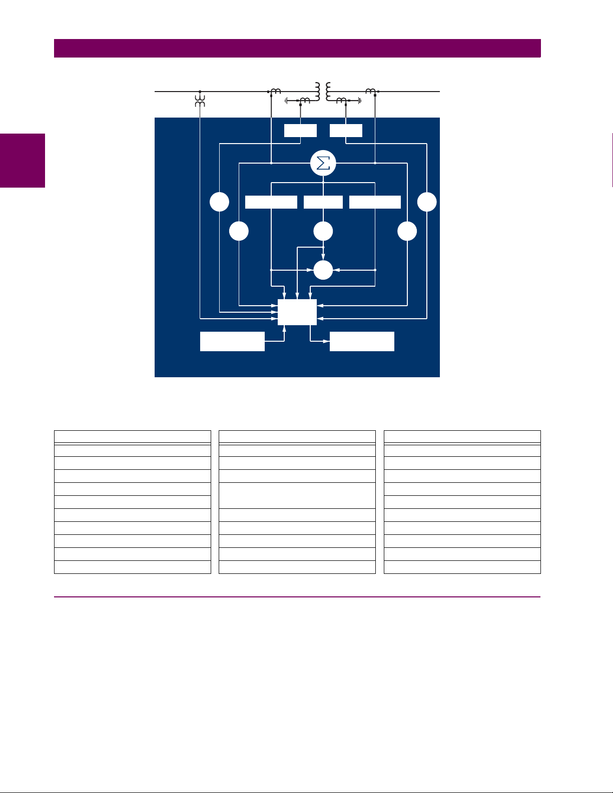
Line Diagram illustrates the relay functionality using ANSI (American National Standards Institute) device numbers.
2
®
/
Table 2–1: DEVICE NUMBERS AND FUNCTIONS
DEVICE
NUMBER
50/87 Instantaneous Differential Overcurrent
51G Ground Time Overcurrent
51P Phase Time Overcurrent
87T Transformer Differential
FUNCTION
GE Multilin T35 Transformer Management Relay 2-1
Page 26
2.1 INTRODUCTION 2 PRODUCT DESCRIPTION
2
Measure
3I_0
51P-1
Calculate
Restraint Amps
Metering
51G
Transducer Input
T35 Transformer Management Relay
Figure 2–1: SINGLE LINE DIAGRAM
Calculate
Operate Amps
50/87
87T
Measure
3I_0
Calculate
2nd, 5th harmonics
FlexElement
51G
51P-2
TM
828725A3.CDR
Table 2–2: OTHER DEVICE FUNCTIONS
FUNCTION FUNCTION FUNCTION
Breaker Arcing Current I
Contact Inputs (up to 96) FlexLogic™ Equations Time Synchronization over SNTP
Contact Outputs (up to 64) IEC 61850 Communications Transducer Inputs/Outputs
Control Pushbuttons Metering: Current, Voltage, Power,
Data Logger User-Programmable Fault Reports
Digital Counters Modbus Communications User Programmable LEDs
Direct Inputs/Outputs (32) Modbus User Map User Programmable Pushbuttons
DNP 3.0 or IEC 60870-5-104 Protocol Non-Volatile Latches User Programmable Self-Tests
Ethernet Global Data (EGD) Protocol Non-Volatile Selector Switch Virtual Inputs (32)
Event Recorder Oscillography Virtual Outputs (64)
2
t FlexElements™ Setting Groups (6)
Power Factor, Frequency
User Definable Displays
2.1.2 ORDERING
The relay is available as a 19-inch rack horizontal mount unit and consists of the following modules: power supply, CPU,
CT/VT, digital input/output, transducer input/output. Each of these modules can be supplied in a number of configurations
specified at the time of ordering. The information required to completely specify the relay is provided in the following table
(see Chapter 3 for full details of relay modules).
2-2 T35 Transformer Management Relay GE Multilin
Page 27

2 PRODUCT DESCRIPTION 2.1 INTRODUCTION
Table 2–3: T35 ORDER CODES
T35 - * 00 - H * * - F ** - H ** - M ** - P ** - U ** - W **
BASE UNIT
CPU
SOFTWARE
MOUNTING
FACEPLATE/ DISPLAY
(applicable only to
horizontal mount units)
POWER SUPPLY
(redundant supply only
available in horizontal units; must
be same type as main supply)
CT/VT MODULES
DIGITAL INPUTS/OUTPUTS
TRANSDUCER
INPUTS/OUTPUTS
(select a maximum of 3 per unit)
INTER-RELAY
COMMUNICATIONS
(select a maximum of 1 per unit)
NOTE
T35 - * 00 - V F * - F ** - H ** - M ** -#**
T35 | | ||| | | | | | |
E
| | | | | | | | | |
G
| | | | | | | | | |
H
| | | | | | | | | |
00
||| | | | | | |
01 ||| | | | | | |
03 ||| | | | | | |
04 ||| | | | | | |
H|| | | | | | |
V F
| | | | | | |
C || | | | | |
P || | | | | |
A || | | | | |
B || | | | | |
D || | | | | |
G || | | | | |
R || | | | | |
S || | | | | |
H | | | | | |
H | | | | | RH
L | | | | | |
L | | | | | RL
8F | 8F | 8F |
8G | 8G | 8G |
8H | 8H | 8H |
8J | 8J | 8J |
For vertical mounting units, # = slot P for digital and transducer
input/output modules; # = slot R for inter-relay communications
modules
XX XX XX XX XX
4A 4A 4A 4A 4A
4B 4B 4B 4B 4B
4C 4C 4C 4C 4C
4L 4L 4L 4L 4L
67 67 67 67 67
6A 6A 6A 6A 6A
6B 6B 6B 6B 6B
6C 6C 6C 6C 6C
6D 6D 6D 6D 6D
6E 6E 6E 6E 6E
6F 6F 6F 6F 6F
6G 6G 6G 6G 6G
6H 6H 6H 6H 6H
6K 6K 6K 6K 6K
6L 6L 6L 6L 6L
6M 6M 6M 6M 6M
6N 6N 6N 6N 6N
6P 6P 6P 6P 6P
6R 6R 6R 6R 6R
6S 6S 6S 6S 6S
6T 6T 6T 6T 6T
6U 6U 6U 6U 6U
5A 5A 5A 5A 5A
5C 5C 5C 5C 5C
5D 5D 5D 5D 5D
5E 5E 5E 5E 5E
5F 5F 5F 5F 5F
For Full Size Horizontal Mount
Reduced Size Vertical Mount (see note below for value of slot #)
Base Unit
RS485 + RS485 (ModBus RTU, DNP)
RS485 + 10BaseF (Ethernet, Modbus TCP/IP, DNP)
RS485 + Redundant 10BaseF (Ethernet, Modbus TCP/IP, DNP)
No Software Options
Ethernet Global Data (EGD); only available with Type G and H CPUs
IEC 61850
Ethernet Global Data and IEC 61850; only available with Type G and H CPUs
Horizontal (19” rack)
Vertical (3/4 rack) with English display
English display
English display with 4 small and 12 large programmable pushbuttons
Chinese display
Chinese display with 4 small and 12 large programmable pushbuttons
French display
French display with 4 small and 12 large programmable pushbuttons
Russian display
Russian display with 4 small and 12 large programmable pushbuttons
125 / 250 V AC/DC power supply
125 / 250 V AC/DC with redundant 125 / 250 V AC/DC power supply
24 to 48 V (DC only) power supply
24 to 48 V (DC only) with redundant 24 to 48 V DC power supply
Standard 4CT/4VT
Sensitive Ground 4CT/4VT
Standard 8CT
Sensitive Ground 8CT
No Module
4 Solid-State (No Monitoring) MOSFET Outputs
4 Solid-State (Voltage w/ opt Current) MOSFET Outputs
4 Solid-State (Current w/ opt Voltage) MOSFET Outputs
14 Form-A (No Monitoring) Latching Outputs
8 Form-A (No Monitoring) Outputs
2 Form-A (Volt w/ opt Curr) & 2 Form-C outputs, 8 Digital Inputs
2 Form-A (Volt w/ opt Curr) & 4 Form-C Outputs, 4 Digital Inputs
8 Form-C Outputs
16 Digital Inputs
4 Form-C Outputs, 8 Digital Inputs
8 Fast Form-C Outputs
4 Form-A (Voltage w/ opt Current) Outputs, 8 Digital Inputs
6 Form-A (Voltage w/ opt Current) Outputs, 4 Digital Inputs
4 Form-C & 4 Fast Form-C Outputs
2 Form-A (Curr w/ opt Volt) & 2 Form-C Outputs, 8 Digital Inputs
2 Form-A (Curr w/ opt Volt) & 4 Form-C Outputs, 4 Digital Inputs
4 Form-A (Current w/ opt Voltage) Outputs, 8 Digital Inputs
6 Form-A (Current w/ opt Voltage) Outputs, 4 Digital Inputs
2 Form-A (No Monitoring) & 2 Form-C Outputs, 8 Digital Inputs
2 Form-A (No Monitoring) & 4 Form-C Outputs, 4 Digital Inputs
4 Form-A (No Monitoring) Outputs, 8 Digital Inputs
6 Form-A (No Monitoring) Outputs, 4 Digital Inputs
4 dcmA Inputs, 4 dcmA Outputs (only one 5A module is allowed)
8 RTD Inputs
4 RTD Inputs, 4 dcmA Outputs (only one 5D module is allowed)
4 RTD Inputs, 4 dcmA Inputs
8 dcmA Inputs
C37.94SM, 1300nm single-mode, ELED, 1 channel single-mode
2A
C37.94SM, 1300nm single-mode, ELED, 2 channel single-mode
2B
Bi-phase, single channel
2E
Bi-phase, dual channel
2F
1550 nm, single-mode, LASER, 1 Channel
72
1550 nm, single-mode, LASER, 2 Channel
73
Channel 1 - RS422; Channel 2 - 1550 nm, single-mode, LASER
74
Channel 1 - G.703; Channel 2 - 1550 nm, Single-mode LASER
75
IEEE C37.94, 820 nm, multimode, LED, 1 Channel
76
IEEE C37.94, 820 nm, multimode, LED, 2 Channels
77
820 nm, multi-mode, LED, 1 Channel
7A
1300 nm, multi-mode, LED, 1 Channel
7B
1300 nm, single-mode, ELED, 1 Ch annel
7C
1300 nm, single-mode, LASER, 1 Channel
7D
Channel 1 - G.703; Channel 2 - 820 nm, multi-mode
7E
Channel 1 - G.703; Channel 2 - 1300 nm, multi-mode
7F
Channel 1 - G.703; Channel 2 - 1300 nm, single-mode ELED
7G
820 nm, multi-mode, LED, 2 Channels
7H
1300 nm, multi-mode, LED, 2 Channels
7I
1300 nm, single-mode, ELED, 2 Channels
7J
1300 nm, single-mode, LASER, 2 Channels
7K
Channel 1 - RS422; Channel 2 - 820 nm, multi-mode, LED
7L
Channel 1 - RS422; Channel 2 - 1300 nm, multi-mode, LED
7M
Channel 1 - RS422; Channel 2 - 1300 nm, single-mode, ELED
7N
Channel 1 - RS422; Channel 2 - 1300 nm, single-mode, LASER
7P
Channel 1 - G.703; Channel 2 - 1300 nm, single-mode LASER
7Q
G.703, 1 Channel
7R
G.703, 2 Channels
7S
RS422, 1 Channel
7T
RS422, 2 Channels
7W
2
GE Multilin T35 Transformer Management Relay 2-3
Page 28

2.1 INTRODUCTION 2 PRODUCT DESCRIPTION
The order codes for replacement modules to be ordered separately are shown in the following table. When ordering a
replacement CPU module or faceplate, please provide the serial number of your existing unit.
Table 2–4: ORDER CODES FOR REPLACEMENT MODULES
POWER SUPPLY
(redundant supply only
available in horizontal units; must
be same type as main supply)
CPU | 9E | RS485 and RS485 (ModBus RTU, DNP 3.0)
2
FACEPLATE/DISPLAY | 3C | Horizontal faceplate with keypad and English display
DIGITAL
INPUTS/OUTPUTS
CT/VT
MODULES
(NOT AVAILABLE FOR THE C30)
UR INTER-RELAY COMMUNICATIONS
TRANSDUCER
INPUTS/OUTPUTS
UR - ** -
| 1H | 125 / 250 V AC/DC
| 1L | 24 to 48 V (DC only)
| RH | redundant 125 / 250 V AC/DC
| RH | redundant 24 to 48 V (DC only)
| 9G | RS485 and 10Base-F (Ethernet, Modbus TCP/IP, DNP 3.0)
| 9H | RS485 and Redundant 10Base-F (Ethernet, ModBus TCP/IP, DNP 3.0)
| 3F | Vertical faceplate with display and keypad
| 3P | Horizontal faceplate with keypad, user-programmable pushbuttons, and English display
| 3R | Horizontal faceplate with keypad and Russian display
| 3S | Horizontal faceplate with keypad, user-programmable pushbuttons, and Russian display
| 4A | 4 Solid-State (no monitoring) MOSFET Outputs
| 4B | 4 Solid-State (voltage with optional current) MOSFET Outputs
| 4C | 4 Solid-State (current with optional voltage) MOSFET Outputs
| 4L | 14 Form-A (no monitoring) Latching Outputs
| 67 | 8 Form-A (no monitoring) Outputs
| 6A | 2 Form-A (voltage with optional current) and 2 Form-C Outputs, 8 Digital Inputs
| 6B | 2 Form-A (voltage with optional current) and 4 Form-C Outputs, 4 Digital Inputs
| 6C | 8 Form-C Outputs
| 6D | 16 Digital Inputs
| 6E | 4 Form-C Outputs, 8 Digital Inputs
| 6F | 8 Fast Form-C Outputs
| 6G | 4 Form-A (voltage with optional current) Outputs, 8 Digital Inputs
| 6H | 6 Form-A (voltage with optional current) Outputs, 4 Digital Inputs
| 6K | 4 Form-C & 4 Fast Form-C Outputs
| 6L | 2 Form-A (current with optional voltage) and 2 Form-C Outputs, 8 Digital Inputs
| 6M | 2 Form-A (current with optional voltage) and 4 Form-C Outputs, 4 Digital Inputs
| 6N | 4 Form-A (current with optional voltage) Outputs, 8 Digital Inputs
| 6P | 6 Form-A (current with optional voltage) Outputs, 4 Digital Inputs
| 6R | 2 Form-A (no monitoring) and 2 Form-C Outputs, 8 Digital Inputs
| 6S | 2 Form-A (no monitoring) and 4 Form-C Outputs, 4 Digital Inputs
| 6T | 4 Form-A (no monitorin g) Outputs, 8 Digital Inputs
| 6U | 6 Form-A (no monitoring) Outputs, 4 Digital Inputs
| 8F | Standard 4CT/4VT
| 8G | Sensitive Ground 4CT/4VT
| 8H | Standard 8CT
| 8J | Sensitive Ground 8CT
|
|
|
|
|
|
|
|
|
|
|
|
|
|
|
|
|
|
|
|
|
|
|
|
|
|
| 5A | 4 dcmA Inputs, 4 dcmA Outputs (only one 5A module is allowed)
| 5C | 8 RTD Inputs
| 5D | 4 RTD Inputs, 4 dcmA Outputs (only one 5D module is allowed)
| 5E | 4 dcmA Inputs, 4 RTD Inputs
| 5F | 8 dcmA Inputs
| C37.94SM, 1300nm single-mode, ELED, 1 channel single-mode
2A
| C37.94SM, 1300nm single-mode, ELED, 2 channel single-mode
2B
| 1550 nm, single-mode, LASER, 1 Channel
72
| 1550 nm, single-mode, LASER, 2 Channel
73
| Channel 1 - RS422; Channel 2 - 1550 nm, single-mode, LASER
74
| Channel 1 - G.703; Channel 2 - 1550 nm, Single-mode LASER
75
| IEEE C37.94, 820 nm, multimode, LED, 1 Channel
76
| IEEE C37.94, 820 nm, multimode, LED, 2 Channels
77
| 820 nm, multi-mode, LED, 1 Channel
7A
| 1300 nm, multi-mode, LED, 1 Channel
7B
| 1300 nm, single-mode, ELED, 1 Channel
7C
| 1300 nm, single-mode, LASER, 1 Channel
7D
| Channel 1 - G.703; Channel 2 - 820 nm, multi-mode
7E
| Channel 1 - G.703; Channel 2 - 1300 nm, multi-mode
7F
| Channel 1 - G.703; Channel 2 - 1300 nm, single-mode ELED
7G
| 820 nm, multi-mode, LED, 2 Channels
7H
| 1300 nm, multi-mode, LED, 2 Channels
7I
| 1300 nm, single-mode, ELED, 2 Channels
7J
| 1300 nm, single-mode, LASER, 2 Channels
7K
| Channel 1 - RS422; Channe l 2 - 820 nm, multi-mode, LED
7L
| Channel 1 - RS422; Channel 2 - 1300 nm, multi-mode, LED
7M
| Channel 1 - RS422; Channel 2 - 1300 nm, single-mode, ELED
7N
| Channel 1 - RS422; Channel 2 - 1300 nm, single-mode, LASER
7P
| Channel 1 - G.703; Channel 2 - 1300 nm, single-mode LASER
7Q
| G.703, 1 Channel
7R
| G.703, 2 Channels
7S
7T
7W
RS422, 1 Channel
RS422, 2 Channels
2-4 T35 Transformer Management Relay GE Multilin
Page 29

2 PRODUCT DESCRIPTION 2.2 SPECIFICATIONS
2.2SPECIFICATIONSSPECIFICATIONS ARE SUBJECT TO CHANGE WITHOUT NOTICE
2.2.1 PROTECTION ELEMENTS
The operating times below include the activation time of a trip rated Form-A output contact unless otherwise indicated. FlexLogic™ operands of a given element are 4 ms faster. This should be taken into account when using
NOTE
FlexLogic™ to interconnect with other protection or control elements of the relay, building FlexLogic™ equations, or
interfacing with other IEDs or power system devices via communications or different output contacts.
PERCENT DIFFERENTIAL
Characteristic: Differential Restraint pre-set
Number of zones: 2
Minimum pickup: 0.05 to 1.00 pu in steps of 0.001
Slope 1 range: 15 to 100% in steps of 1%
Slope 2 range: 50 to 100% in steps of 1%
Kneepoint 1: 1.0 to 2.0 pu in steps of 0.0001
Kneepoint 2: 2.0 to 30.0 pu in steps of 0.0001
nd
harmonic inhibit level: 1.0 to 40.0% in steps of 0.1
2
nd
harmonic inhibit function: Adaptive, Traditional, Disabled
2
nd
harmonic inhibit mode: Per-phase, 2-out-of-3, Average
2
th
harmonic inhibit range: 1.0 to 40.0% in steps of 0.1
5
Operate times:
Harmonic inhibits selected: 20 to 30 ms
No harmonic inhibits selected: 5 to 20 ms
Dropout level: 97 to 98% of pickup
Level accuracy: ±0.5% of reading or ±1% of rated
(whichever is greater)
INSTANTANEOUS DIFFERENTIAL
Pickup level: 2.00 to 30.00 pu in steps of 0.01
Dropout level: 97 to 98% of pickup
Level accuracy: ±0.5% of reading or ±1% of rated
(whichever is greater)
Operate time: < 20 ms at 3 × pickup at 60 Hz
PHASE/GROUND TOC
Current: Phasor or RMS
Pickup level: 0.000 to 30.000 pu in steps of 0.001
Dropout level: 97% to 98% of Pickup
Level accuracy:
for 0.1 to 2.0 × CT: ±0.5% of reading or ±1% of rated
(whichever is greater)
for > 2.0 × CT: ±1.5% of reading > 2.0 × CT rating
Curve shapes: IEEE Moderately/Very/Extremely
Curve multiplier: Time Dial = 0.00 to 600.00 in steps of
Reset type: Instantaneous/Timed (per IEEE)
Timing accuracy: Operate at > 1.03 × actual Pickup
Inverse; IEC (and BS) A/B/C and Short
Inverse; GE IAC Inverse, Short/Very/
Extremely Inverse; I
(programmable); Definite Time (0.01 s
base curve)
0.01
±3.5% of operate time or ±½ cycle
(whichever is greater)
2
t; FlexCurves™
BREAKER ARCING CURRENT
Principle: accumulates breaker duty (I2t) and mea-
Initiation: programmable per phase from any Flex-
Compensation for auxiliary relays: 0 to 65.535 s in steps of 0.001
Alarm threshold: 0 to 50000 kA2-cycle in steps of 1
Fault duration accuracy: 0.25 of a power cycle
Availability: 1 per CT bank with a minimum of 2
sures fault duration
Logic™ operand
2
GE Multilin T35 Transformer Management Relay 2-5
Page 30

2.2 SPECIFICATIONS 2 PRODUCT DESCRIPTION
2.2.2 USER-PROGRAMMABLE ELEMENTS
FLEXLOGIC™
Programming language: Reverse Polish Notation with graphical
visualization (keypad programmable)
Lines of code: 512
Internal variables: 64
Supported operations: NOT, XOR, OR (2 to 16 inputs), AND (2
2
Inputs: any logical variable, contact, or virtual
Number of timers: 32
Pickup delay: 0 to 60000 (ms, sec., min.) in steps of 1
Dropout delay: 0 to 60000 (ms, sec., min.) in steps of 1
to 16 inputs), NOR (2 to 16 inputs),
NAND (2 to 16 inputs), Latch (Reset
dominant), Edge Detectors, Timers
input
FLEXCURVES™
Number: 4 (A through D)
Reset points: 40 (0 through 1 of pickup)
Operate points: 80 (1 through 20 of pickup)
Time delay: 0 to 65535 ms in steps of 1
FLEX STATES
Number: up to 256 logical variables grouped
Programmability: any logical variable, contact, or virtual
under 16 Modbus addresses
input
FLEXELEMENTS™
Number of elements: 16
Operating signal: any analog actual value, or two values in
differential mode
Operating signal mode: Signed or Absolute Value
Operating mode: Level, Delta
Comparator direction: Over, Under
Pickup Level: –30.000 to 30.000 pu in steps of 0.001
Hysteresis: 0.1 to 50.0% in steps of 0.1
Delta dt: 20 ms to 60 days
Pickup & dropout delay: 0.000 to 65.535 s in steps of 0.001
NON-VOLATILE LATCHES
Type: Set-dominant or Reset-dominant
Number: 16 (individually programmed)
Output: Stored in non-volatile memory
Execution sequence: As input prior to protection, control, and
FlexLogic™
USER-PROGRAMMABLE LEDs
Number: 48 plus Trip and Alarm
Programmability: from any logical variable, contact, or vir-
tual input
Reset mode: Self-reset or Latched
LED TEST
Initiation: from any digital input or user-program-
mable condition
Number of tests: 3, interruptible at any time
Duration of full test: approximately 3 minutes
Test sequence 1: all LEDs on
Test sequence 2: all LEDs off, one LED at a time on for 1 s
Test sequence 3: all LEDs on, one LED at a time off for 1 s
USER-DEFINABLE DISPLAYS
Number of displays: 16
Lines of display: 2 × 20 alphanumeric characters
Parameters: up to 5, any Modbus register addresses
Invoking and scrolling: keypad, or any user-programmable con-
dition, including pushbuttons
CONTROL PUSHBUTTONS
Number of pushbuttons: 7
Operation: drive FlexLogic™ operands
USER-PROGRAMMABLE PUSHBUTTONS (OPTIONAL)
Number of pushbuttons: 12
Mode: Self-Reset, Latched
Display message: 2 lines of 20 characters each
SELECTOR SWITCH
Number of elements: 2
Upper position limit: 1 to 7 in steps of 1
Selecting mode: Time-out or Acknowledge
Time-out timer: 3.0 to 60.0 s in steps of 0.1
Control inputs: step-up and 3-bit
Power-up mode: restore from non-volatile memory or syn-
chronize to a 3-bit control input
2-6 T35 Transformer Management Relay GE Multilin
Page 31

2 PRODUCT DESCRIPTION 2.2 SPECIFICATIONS
2.2.3 MONITORING
OSCILLOGRAPHY
Maximum records: 64
Sampling rate: 64 samples per power cycle
Triggers: Any element pickup, dropout or operate
Digital input change of state
Digital output change of state
FlexLogic™ equation
Data: AC input channels
Element state
Digital input state
Digital output state
Data storage: In non-volatile memory
EVENT RECORDER
Capacity: 1024 events
Time-tag: to 1 microsecond
Triggers: Any element pickup, dropout or operate
Digital input change of state
Digital output change of state
Self-test events
Data storage: In non-volatile memory
RMS CURRENT: PHASE, NEUTRAL, AND GROUND
Accuracy at
0.1 to 2.0 × CT rating: ±0.25% of reading or ±0.1% of rated
(whichever is greater)
> 2.0 × CT rating: ±1.0% of reading
RMS VOLTAGE
Accuracy: ±0.5% of reading from 10 to 208 V
REAL POWER (WATTS)
Accuracy: ±1.0% of reading at
–0.8 < PF ≤ –1.0 and 0.8 < PF ≤ 1.0
USER-PROGRAMMABLE FAULT REPORT
Number of elements: 2
Pre-fault trigger: any FlexLogic™ operand
Fault trigger: any FlexLogic™ operand
Recorder quantities: 32 (any FlexAnalog value)
DATA LOGGER
Number of channels: 1 to 16
Parameters: Any available analog actual value
Sampling rate: 1 sec.; 1, 5, 10, 15, 20, 30, 60 min.
Storage capacity: (NN is dependent on memory)
1-second rate: 01 channel for NN days
16 channels for NN days
↓↓
60-minute rate: 01 channel for NN days
16 channels for NN days
2.2.4 METERING
REACTIVE POWER (VARS)
Accuracy: ±1.0% of reading at –0.2 ≤ PF ≤ 0.2
APPARENT POWER (VA)
Accuracy: ±1.0% of reading
FREQUENCY
Accuracy at
V = 0.8 to 1.2 pu: ±0.01 Hz (when voltage signal is used
for frequency measurement)
I = 0.1 to 0.25 pu: ±0.05 Hz
I > 0.25 pu: ±0.02 Hz (when current signal is used for
frequency measurement)
2
GE Multilin T35 Transformer Management Relay 2-7
Page 32

2.2 SPECIFICATIONS 2 PRODUCT DESCRIPTION
2.2.5 INPUTS
AC CURRENT
CT rated primary: 1 to 50000 A
CT rated secondary: 1 A or 5 A by connection
Nominal frequency: 20 to 65 Hz
Relay burden: < 0.2 VA at rated secondary
Conversion range:
2
Standard CT: 0.02 to 46 × CT rating RMS symmetrical
Sensitive Ground module:
0.002 to 4.6 × CT rating RMS symmetrical
Current withstand: 20 ms at 250 times rated
1 sec. at 100 times rated
continuous at 3 times rated
AC VOLTAGE
VT rated secondary: 50.0 to 240.0 V
VT ratio: 1.00 to 24000.00
Nominal frequency: 20 to 65 Hz
Relay burden: < 0.25 VA at 120 V
Conversion range: 1 to 275 V
Voltage withstand: continuous at 260 V to neutral
1 min./hr at 420 V to neutral
CONTACT INPUTS
Dry contacts: 1000 Ω maximum
Wet contacts: 300 V DC maximum
Selectable thresholds: 17 V, 33 V, 84 V, 166 V
Tolerance: ±10%
Recognition time: < 1 ms
Debounce timer: 0.0 to 16.0 ms in steps of 0.5
DCMA INPUTS
Current input (mA DC): 0 to –1, 0 to +1, –1 to +1, 0 to 5, 0 to 10,
Input impedance: 379 Ω ±10%
Conversion range: –1 to + 20 mA DC
Accuracy: ±0.2% of full scale
Type: Passive
0 to 20, 4 to 20 (programmable)
RTD INPUTS
Types (3-wire): 100 Ω Platinum, 100 & 120 Ω Nickel, 10
Ω Copper
Sensing current: 5 mA
Range: –50 to +250°C
Accuracy: ±2°C
Isolation: 36 V pk-pk
IRIG-B INPUT
Amplitude modulation: 1 to 10 V pk-pk
DC shift: TTL
Input impedance: 22 kΩ
Isolation: 2 kV
REMOTE INPUTS (MMS GOOSE)
Number of input points: 32, configured from 64 incoming bit pairs
Number of remote devices:16
Default states on loss of comms.: On, Off, Latest/Off, Latest/On
DIRECT INPUTS
Number of input points: 32
No. of remote devices: 16
Default states on loss of comms.: On, Off, Latest/Off, Latest/On
Ring configuration: Yes, No
Data rate: 64 or 128 kbps
CRC: 32-bit
CRC alarm:
Responding to: Rate of messages failing the CRC
Monitoring message count: 10 to 10000 in steps of 1
Alarm threshold: 1 to 1000 in steps of 1
Unreturned message alarm:
Responding to: Rate of unreturned messages in the ring
configuration
Monitoring message count: 10 to 10000 in steps of 1
Alarm threshold: 1 to 1000 in steps of 1
2.2.6 POWER SUPPLY
LOW RANGE
Nominal DC voltage: 24 to 48 V at 3 A
Min/max DC voltage: 20 / 60 V
NOTE: Low range is DC only.
HIGH RANGE
Nominal DC voltage: 125 to 250 V at 0.7 A
Min/max DC voltage: 88 / 300 V
Nominal AC voltage: 100 to 240 V at 50/60 Hz, 0.7 A
Min/max AC voltage: 88 / 265 V at 48 to 62 Hz
ALL RANGES
Volt withstand: 2 × Highest Nominal Voltage for 10 ms
Voltage loss hold-up: 50 ms duration at nominal
Power consumption: Typical = 15 VA; Max. = 30 VA
INTERNAL FUSE
RATINGS
Low range power supply: 7.5 A / 600 V
High range power supply: 5 A / 600 V
INTERRUPTING CAPACITY
AC: 100 000 A RMS symmetrical
DC: 10 000 A
2-8 T35 Transformer Management Relay GE Multilin
Page 33

2 PRODUCT DESCRIPTION 2.2 SPECIFICATIONS
2.2.7 OUTPUTS
FORM-A RELAY
Make and carry for 0.2 s: 30 A as per ANSI C37.90
Carry continuous: 6 A
Break at L/R of 40 ms: 0.25 A DC max. at 48 V
0.10 A DC max. at 125 V
Operate time: < 4 ms
Contact material: Silver alloy
LATCHING RELAY
Make and carry for 0.2 s: 30 A as per ANSI C37.90
Carry continuous: 6 A
Break at L/R of 40 ms: 0.25 A DC max.
Operate time: < 4 ms
Contact material: Silver alloy
Control: separate operate and reset inputs
Control mode: operate-dominant or reset-dominant
FORM-A VOLTAGE MONITOR
Applicable voltage: approx. 15 to 250 V DC
Trickle current: approx. 1 to 2.5 mA
FORM-A CURRENT MONITOR
Threshold current: approx. 80 to 100 mA
FORM-C AND CRITICAL FAILURE RELAY
Make and carry for 0.2 s: 10 A
Carry continuous: 6 A
Break at L/R of 40 ms: 0.25 A DC max. at 48 V
0.10 A DC max. at 125 V
Operate time: < 8 ms
Contact material: Silver alloy
FAST FORM-C RELAY
Make and carry: 0.1 A max. (resistive load)
Minimum load impedance:
INPUT
VOLTAGE
250 V DC 20 KΩ 50 KΩ
120 V DC 5 KΩ 2 KΩ
48 V DC 2 KΩ 2 KΩ
24 V DC 2 KΩ 2 KΩ
Note: values for 24 V and 48 V are the same due to a
required 95% voltage drop across the load impedance.
Operate time: < 0.6 ms
Internal Limiting Resistor: 100 Ω, 2 W
2 W RESISTOR 1 W RESISTOR
IMPEDANCE
SOLID-STATE OUTPUT RELAY
Operate and release time: <100 µs
Maximum voltage: 265 V DC
Maximum continuous current: 5 A at 45°C; 4 A at 65°C
Make and carry for 0.2 s: as per ANSI C37.90
Breaking capacity:
Operations/
interval
Break
capability
(0 to 250 V
DC)
IEC 647-5 / UL508 Utility
5000 ops /
1 s-On, 9 s-Off
1000 ops /
0.5 s-On, 0.5 s-Off
3.2 A
L/R = 10 ms
1.6 A
L/R = 20 ms
0.8 A
L/R = 40 ms
application
(autoreclose
scheme)
5ops/
0.2 s-On,
0.2 s-Off
within 1
minute
10 A
L/R = 40 ms
Industrial
application
10000 ops /
0.2 s-On,
30 s-Off
10 A
L/R = 40 ms
IRIG-B OUTPUT
Amplitude: 10 V peak-peak RS485 level
Maximum load: 100 ohms
Time delay: 1 ms for AM input
40 µs for DC-shift input
Isolation: 2 kV
CONTROL POWER EXTERNAL OUTPUT
(FOR DRY CONTACT INPUT)
Capacity: 100 mA DC at 48 V DC
Isolation: ±300 Vpk
REMOTE OUTPUTS (IEC 61850 GSSE/GOOSE)
Standard output points: 32
User output points: 32
DIRECT OUTPUTS
Output points: 32
DCMA OUTPUTS
Range: –1 to 1 mA, 0 to 1 mA, 4 to 20 mA
Max. load resistance: 12 kΩ for –1 to 1 mA range
12 kΩ for 0 to 1 mA range
600 Ω for 4 to 20 mA range
Accuracy: ±0.75% of full-scale for 0 to 1 mA range
99% Settling time to a step change: 100 ms
Isolation: 1.5 kV
Driving signal: any FlexAnalog quantity
Upper and lower limit for the driving signal: –90 to 90 pu in steps of
±0.5% of full-scale for –1 to 1 mA range
±0.75% of full-scale for 0 to 20 mA range
0.001
2
GE Multilin T35 Transformer Management Relay 2-9
Page 34
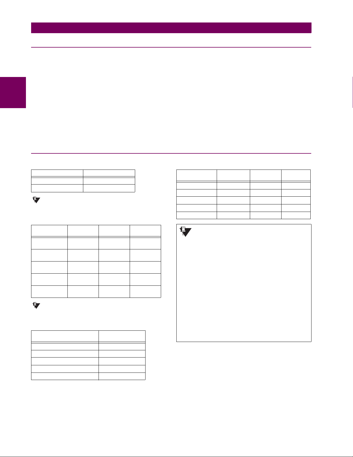
2.2 SPECIFICATIONS 2 PRODUCT DESCRIPTION
2.2.8 COMMUNICATIONS
RS232
Front port: 19.2 kbps, Modbus® RTU
RS485
1 or 2 rear ports: Up to 115 kbps, Modbus® RTU, isolated
Typical distance: 1200 m
2
Isolation: 2 kV
together at 36 Vpk
SHIELDED TWISTED-PAIR INTERFACE OPTIONS
INTERFACE TYPE TYPICAL DISTANCE
RS422 1200 m
G.703 100 m
RS422 distance is based on transmitter power
NOTE
and does not take into consideration the clock
source provided by the user.
LINK POWER BUDGET
EMITTER,
FIBER TYPE
820 nm LED,
Multimode
1300 nm LED,
Multimode
1300 nm ELED,
Singlemode
1300 nm Laser,
Singlemode
1550 nm Laser,
Singlemode
TRANSMIT
POWER
–20 dBm –30 dBm 10 dB
–21 dBm –30 dBm 9 dB
–21 dBm –30 dBm 9 dB
–1 dBm –30 dBm 29 dB
+5 dBm –30 dBm 35 dB
RECEIVED
SENSITIVITY
These Power Budgets are calculated from the
NOTE
manufacturer’s worst-case transmitter power
and worst case receiver sensitivity.
MAXIMUM OPTICAL INPUT POWER
EMITTER, FIBER TYPE MAX. OPTICAL
820 nm LED, Multimode –7.6 dBm
1300 nm LED, Multimode –11 dBm
1300 nm ELED, Singlemode –14 dBm
1300 nm Laser, Singlemode –14 dBm
1550 nm Laser, Singlemode –14 dBm
INPUT POWER
POWER
BUDGET
ETHERNET PORT
10Base-F: 820 nm, multi-mode, supports half-
duplex/full-duplex fiber optic with ST
connector
Redundant 10Base-F: 820 nm, multi-mode, half-duplex/full-
10Base-T: RJ45 connector
Power budget: 10 db
Max optical input power: –7.6 dBm
Max optical output power: –20 dBm
Receiver sensitivity: –30 dBm
Typical distance: 1.65 km
SNTP clock synchronization error: <10 ms (typical)
duplex fiber optic with ST connector
2.2.9 INTER-RELAY COMMUNICATIONS
TYPICAL LINK DISTANCE
EMITTER TYPE FIBER TYPE CONNECTOR
820 nm LED Multimode ST 1.65 km
1300 nm LED Multimode ST 3.8 km
1300 nm ELED Singlemode ST 11.4 km
1300 nm Laser Singlemode ST 64 km
1550 nm Laser Singlemode ST 105 km
TYPE
TYPICAL
DISTANCE
Typical distances listed are based on the following assumptions for system loss. As
NOTE
actual losses will vary from one installation to
another, the distance covered by your system
may vary.
CONNECTOR LOSSES (TOTAL OF BOTH ENDS)
ST connector 2 dB
FIBER LOSSES
820 nm multimode 3 dB/km
1300 nm multimode 1 dB/km
1300 nm singlemode 0.35 dB/km
1550 nm singlemode 0.25 dB/km
Splice losses: One splice every 2 km,
at 0.05 dB loss per splice.
SYSTEM MARGIN
3 dB additional loss added to calculations to compensate for
all other losses.
Compensated difference in transmitting and receiving (channel
asymmetry) channel delays using GPS satellite clock: 10 ms
2-10 T35 Transformer Management Relay GE Multilin
Page 35

2 PRODUCT DESCRIPTION 2.2 SPECIFICATIONS
NOTE
2.2.10 ENVIRONMENTAL
OPERATING TEMPERATURES
Cold: IEC 60028-2-1, 16 h at –40°C
Dry Heat: IEC 60028-2-2, 16 h at +85°C
Electrical fast transient: ANSI/IEEE C37.90.1
IEC 61000-4-4
IEC 60255-22-4
Oscillatory transient: ANSI/IEEE C37.90.1
IEC 61000-4-12
Insulation resistance: IEC 60255-5
Dielectric strength: IEC 60255-6
ANSI/IEEE C37.90
Electrostatic discharge: EN 61000-4-2
Surge immunity: EN 61000-4-5
RFI susceptibility: ANSI/IEEE C37.90.2
IEC 61000-4-3
IEC 60255-22-3
Ontario Hydro C-5047-77
THERMAL
Products go through an environmental test based upon an
Accepted Quality Level (AQL) sampling process.
OTHER
Humidity (noncondensing): IEC 60068-2-30, 95%, Variant 1, 6
days
Altitude: Up to 2000 m
Installation Category: II
2.2.11 TYPE TESTS
Conducted RFI: IEC 61000-4-6
Voltage dips/interruptions/variations:
IEC 61000-4-11
IEC 60255-11
Power frequency magnetic field immunity:
IEC 61000-4-8
Vibration test (sinusoidal): IEC 60255-21-1
Shock and bump: IEC 60255-21-2
Type test report available upon request.
2.2.12 PRODUCTION TESTS
2
APPROVALS
UL Listed for the USA and Canada
MOUNTING
Attach mounting brackets using 20 inch-pounds (±2 inch-pounds)
of torque.
2.2.13 APPROVALS
CE:
LVD 73/23/EEC: IEC 1010-1
EMC 81/336/EEC: EN 50081-2, EN 50082-2
2.2.14 MAINTENANCE
CLEANING
Normally, cleaning is not required; but for situations where dust
has accumulated on the faceplate display, a dry cloth can be used.
GE Multilin T35 Transformer Management Relay 2-11
Page 36

2
2.2 SPECIFICATIONS 2 PRODUCT DESCRIPTION
2-12 T35 Transformer Management Relay GE Multilin
Page 37

3 HARDWARE 3.1 DESCRIPTION
3 HARDWARE 3.1DESCRIPTION 3.1.1 PANEL CUTOUT
The relay is available as a 19-inch rack horizontal mount unit with a removable faceplate. The modular design allows the
relay to be easily upgraded or repaired by a qualified service person. The faceplate is hinged to allow easy access to the
removable modules, and is itself removable to allow mounting on doors with limited rear depth. There is also a removable
dust cover that fits over the faceplate, which must be removed when attempting to access the keypad or RS232 communications port.
The horizontal case dimensions are shown below, along with panel cutout details for panel mounting. When planning the
location of your panel cutout, ensure that provision is made for the faceplate to swing open without interference to or from
adjacent equipment.
The relay must be mounted such that the faceplate sits semi-flush with the panel or switchgear door, allowing the operator
access to the keypad and the RS232 communications port. The relay is secured to the panel with the use of four screws
supplied with the relay.
3
Figure 3–1: T35 HORIZONTAL MOUNTING AND DIMENSIONS
GE Multilin T35 Transformer Management Relay 3-1
Page 38

3.1 DESCRIPTION 3 HARDWARE
3.1.2 MODULE WITHDRAWAL AND INSERTION
Module withdrawal and insertion may only be performed when control power has been removed from the
WARNING
unit. Inserting an incorrect module type into a slot may result in personal injury, damage to the unit or connected equipment, or undesired operation!
Proper electrostatic discharge protection (i.e. a static strap) must be used when coming in contact with
WARNING
modules while the relay is energized!
The relay, being modular in design, allows for the withdrawal and insertion of modules. Modules must only be replaced with
like modules in their original factory configured slots. The faceplate can be opened to the left, once the sliding latch on the
right side has been pushed up, as shown below. This allows for easy accessibility of the modules for withdrawal.
3
Figure 3–2: UR MODULE WITHDRAWAL/INSERTION
• MODULE WITHDRAWAL: The ejector/inserter clips, located at the top and bottom of each module, must be pulled
simultaneously to release the module for removal. Before performing this action, control power must be removed
from the relay. Record the original location of the module to ensure that the same or replacement module is inserted
into the correct slot. Modules with current input provide automatic shorting of external CT circuits.
• MODULE INSERTION: Ensure that the correct module type is inserted into the correct slot position. The ejector/
inserter clips located at the top and at the bottom of each module must be in the disengaged position as the module is
smoothly inserted into the slot. Once the clips have cleared the raised edge of the chassis, engage the clips simultaneously. When the clips have locked into position, the module will be fully inserted.
Type 9G and 9H CPU modules are equipped with 10Base-T and 10Base-F Ethernet connectors. These connectors
must be individually disconnected from the module before the it can be removed from the chassis.
NOTE
The version 4.0 release of the T35 relay includes new hardware (CPU and CT/VT modules). The new CPU modules are specified with the following order codes: 9E, 9G, and 9H. The new CT/VT modules are specified with the
NOTE
following order codes: 8F, 8G, 8H, 8J.
The new CT/VT modules (8F, 8G, 8H, 8J) can only be used with the new CPUs (9E, 9G, 9H); similarly, the old CT/
VT modules (8A, 8B, 8C, 8D) can only be used with the old CPUs (9A, 9C, 9D). To prevent hardware mismatches,
the new CPU and CT/VT modules have blue labels and a warning sticker stating “Attn.: Ensure CPU and DSP
module label colors are the same!”. In the event that there is a mismatch between the CPU and CT/VT module,
the relay will not function and a
DSP ERROR or HARDWARE MISMATCH error will be displayed.
All other input/output modules are compatible with the new hardware. Firmware versions 4.0x and higher are only
compatible with the new CPU and CT/VT modules. Previous versions of the firmware (3.4x and earlier) are only
compatible with the older CPU and CT/VT modules.
3-2 T35 Transformer Management Relay GE Multilin
Page 39
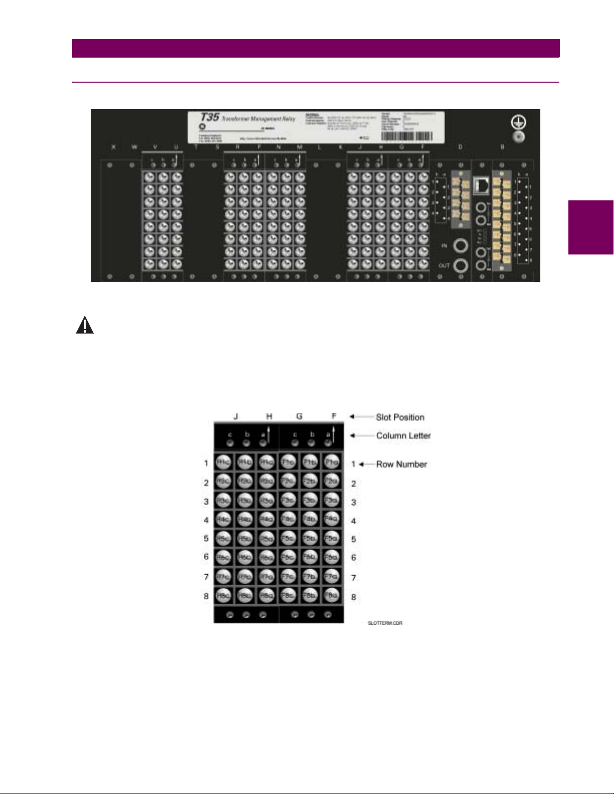
3 HARDWARE 3.1 DESCRIPTION
WARNING
3.1.3 REAR TERMINAL LAYOUT
828746A1.CDR
Figure 3–3: REAR TERMINAL VIEW
Do not touch any rear terminals while the relay is energized!
3
The relay follows a convention with respect to terminal number assignments which are three characters long assigned in
order by module slot position, row number, and column letter. Two-slot wide modules take their slot designation from the
first slot position (nearest to CPU module) which is indicated by an arrow marker on the terminal block. See the following
figure for an example of rear terminal assignments.
Figure 3–4: EXAMPLE OF MODULES IN F AND H SLOTS
GE Multilin T35 Transformer Management Relay 3-3
Page 40

3.2 WIRING 3 HARDWARE
3.2WIRING 3.2.1 TYPICAL WIRING
25 PIN
6
6
6
6a
H
6
H
TRANSFORMER MANAGEMENT RELAY
T35
POWER
LO
6b
B
B
CONNECTOR
5
4
22
8
9
7
PERSONAL
COMPUTER
9 PIN
7
9
8
CONNECTOR
6c
6b
H
H
V
6D
DIGITAL I/O
POWER SUPPLY 1
FILTER
SURGE
6a
8b
8a
B
B
D1b
RS485
COM 1
D2b
P
8
6C
P
7
P
6
P
5
P
4
P
3
P
2
P
1
DIGITAL I/O
SURGE
U
U
RS485
com
D3b
D1a
D2a
RS-232
DB-9
828747A3.CDR
(front)
P
8c
P
8b
8a
P
7c
P
P
7b
P
7a
6c
P
6b
P
6a
P
5c
P
P
5b
P
5a
P
4c
P
4b
P
4a
P
3c
P
3b
3a
P
P
2c
P
2b
P
2a
1c
P
P
1b
P
1a
U
8b
COMMON 7b
7b
UU
8c
UU
CONTACT IN 8c
8a
CONTACT IN 8a
UU
CONTACT IN 7c
7c
UU
7a
CONTACT IN 7a
UU
COMMON 5b
5b
UU
6c
UU
CONTACT IN 6c
6a
CONTACT IN 6a
UU
5c
CONTACT IN 5c
UU
5a
UU
CONTACT IN 5a
3b
COMMON 3b
U
UU
CONTACT IN 4c
4c
4a
CONTACT IN 4a
UU
3c
CONTACT IN 3c
UU
3a
CONTACT IN 3a
UU
1b
UU
COMMON 1b
2c
UU
CONTACT IN 2c
2a
UU
CONTACT IN 2a
1c
UU
CONTACT IN 1c
1a
U
CONTACT IN 1a
CPU 9E
IRIG-B
Input
IRIG-B
Output
COM 2
com
BNC
BNC
D3a
D4b
GROUND BUS
D4a
1
B
Power
Supply
9
D
CPU
F
8
G
CT/VT
H
6
I/O
J
K
MXL
(Rear View)
6
CT
N
MODULE ARRANGEMENT
6
*
I/O
R
SP
T
U
6
*
I/O
V
W
* Optional
WITH NO
CONTROL POWER
CONTACTS SHOWN
3
TYPICAL CONFIGURATION
THE AC SIGNAL PATH IS CONFIGURABLE
OPEN DELTA
B
C
A
(5 amp CTs)
WINDING 2
WINDING 1
VT CONNECTION (ABC)
B
A
(5 amp CTs)
WINDING 3
TXD
RXD
SGND
2
8
7
3
20
1
2
3
4
5
COMPUTER
1
2
3
4
5
UR
TXD
RXD
C
VOLT &
CURRENT SUPV.
IG1
M
8c
M
8b
M
8a
M
7c
M
7b
M
7a
M
6c
M
6b
M
6a
M
5c
M
5b
M
5a
M
4c
M
4b
M
4a
M
3c
3b
M
M
3a
M
2c
M
2b
M
2a
M
1c
M
1b
M
1a
4c
F
4b
F
4a
F
3c
F
3b
F
3a
F
2c
F
2b
F
2a
F
1c
F
1b
F
1a
F
8c
F
8a
F
7c
F
7a
F
6c
F
6a
F
F
5c
F
5a
7c
F
F
7a
6c
F
F
6a
F
5c
F
5a
IG
IC
IB
IA
IG
IC
IB
IA
IG
IC
IB
IA
VX
VC
VB
VA
VC
VB
VA
IG5
IC1
IC5
IB1
IB5
IA1
IA5
IG1
IG5
IC1
IC5
IB1
IB5
IA1
IA5
IG1
IG5
IC1
IC5
IB1
IB5
IA1
IA5
VX
VC
VB
VA
VC
VB
VA
1a
1c
1b
H
H
H
I
V
1
H
6H
8H / 8J
CURRENT INPUTS
CURRENT INPUTS
8F/ 8G
VOLTAGE INPUTS
DIGITAL I/O
H
H
H
CONTACT IN 8a
CONTACT IN 7a
CONTACT IN 7c
VOLTAGE INPUTS
7c
8a
7a
H
H
H
2a
3a
2c
2b
H
H
H
H
I
I
V
2
H
H
H
SURGE
COMMON 7b
CONTACT IN 8c
7b
8c
8b
H
H
H
VOLTAGE SUPV.
1
TC
SGND
2
TC
5a
4a
4c
5c
3c
4b
5b
3b
H
H
H
H
H
H
H
H
I
IVI
V
V
4
5
3
H
H
H
GE Multilin
48 VDC
FAILURE
OUTPUT
CRITICAL
CONTROL
HI
MED
3b
2b
1b
1a
3a
5a
5b
B
B
B
B
B
B
B
C
B
A
DC
( DC ONLY )
AC or DC
Shielded
twisted pairs
Device
Remote
Ground at
Co-axial *
Co-axial
No. 10AWG
Co-axial
Minimum
PROVIDED
TERMINAL IS
GROUNDED IF
MODULES MUST BE
only use one
terminal as input
Co-axial * - For IRIG-B Input
This diagram is based on the following order code: T35-E00-HCH-F8F-H6H-K6D-M8H-P6C-U8H-WXX.
The purpose of this diagram is to provide an example of how the relay is typically wired, not specifically how to wire your own relay. Please refer to the following pages for
examples to help you wire your relay correctly based on your own relay configuration and order code.
CAUTION
Figure 3–5: TYPICAL WIRING DIAGRAM
3-4 T35 Transformer Management Relay GE Multilin
Page 41
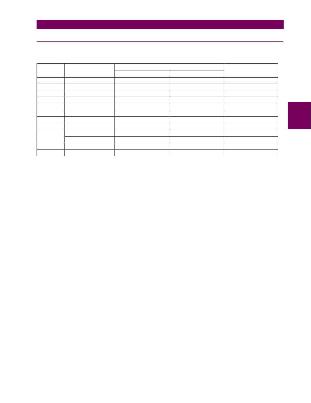
3 HARDWARE 3.2 WIRING
3.2.2 DIELECTRIC STRENGTH
The dielectric strength of the UR-series module hardware is shown in the following table:
Table 3–1: DIELECTRIC STRENGTH OF UR-SERIES MODULE HARDWARE
MODULE
TYPE
1 Power Supply High (+); Low (+); (–) Chassis 2000 V AC for 1 minute
1 Power Supply 48 V DC (+) and (–) Chassis 2000 V AC for 1 minute
1 Power Supply Relay Terminals Chassis 2000 V AC for 1 minute
2 Reserved N/A N/A N/A
3 Reserved N/A N/A N/A
4 Reserved N/A N/A N/A
5 Analog Inputs/Outputs All except 8b Chassis < 50 V DC
6 Digital Inputs/Outputs All (See Precaution 2) Chassis 2000 V AC for 1 minute
7
8 CT/VT All Chassis 2000 V AC for 1 minute
9 CPU All Chassis 2000 V AC for 1 minute
MODULE FUNCTION TERMINALS DIELECTRIC STRENGTH
FROM TO
G.703 All except 2b, 3a, 7b, 8a Chassis 2000 V AC for 1 minute
RS422 All except 6a, 7b, 8a Chassis < 50 V DC
(AC)
Filter networks and transient protection clamps are used in module hardware to prevent damage caused by high peak voltage transients, radio frequency interference (RFI) and electromagnetic interference (EMI). These protective components
can be damaged by application of the ANSI/IEEE C37.90 specified test voltage for a period longer than the specified one
minute.
3
GE Multilin T35 Transformer Management Relay 3-5
Page 42

3.2 WIRING 3 HARDWARE
3.2.3 CONTROL POWER
CONTROL POWER SUPPLIED TO THE RELAY MUST BE CONNECTED TO THE MATCHING POWER SUPPLY
RANGE OF THE RELAY. IF THE VOLTAGE IS APPLIED TO THE WRONG TERMINALS, DAMAGE MAY
CAUTION
OCCUR!
The T35 relay, like almost all electronic relays, contains electrolytic capacitors. These capacitors are well
known to be subject to deterioration over time if voltage is not applied periodically. Deterioration can be
NOTE
avoided by powering the relays up once a year.
The power supply module can be ordered for two possible voltage ranges. Each range has a dedicated input connection for
proper operation. The ranges are as shown below (see the Technical Specifications section for additional details):
• LO range: 24 to 48 V (DC only) nominal
• HI range: 125 to 250 V nominal
3
The power supply module provides power to the relay and supplies power for dry contact input connections.
The power supply module provides 48 V DC power for dry contact input connections and a critical failure relay (see the
Typical Wiring Diagram earlier). The critical failure relay is a Form-C that will be energized once control power is applied
and the relay has successfully booted up with no critical self-test failures. If on-going self-test diagnostic checks detect a
critical failure (see the Self-Test Errors table in Chapter 7) or control power is lost, the relay will de-energize.
Figure 3–6: CONTROL POWER CONNECTION
3.2.4 CT/VT MODULES
A CT/VT module may have voltage inputs on Channels 1 through 4 inclusive, or Channels 5 through 8 inclusive. Channels
1 and 5 are intended for connection to Phase A, and are labeled as such in the relay. Channels 2 and 6 are intended for
connection to Phase B, and are labeled as such in the relay. Channels 3 and 7 are intended for connection to Phase C and
are labeled as such in the relay. Channels 4 and 8 are intended for connection to a single phase source. If voltage, this
channel is labelled the auxiliary voltage (VX). If current, this channel is intended for connection to a CT between a system
neutral and ground, and is labelled the ground current (IG).
a) CT INPUTS
VERIFY THAT THE CONNECTION MADE TO THE RELAY NOMINAL CURRENT OF 1 A OR 5 A MATCHES
THE SECONDARY RATING OF THE CONNECTED CTs. UNMATCHED CTs MAY RESULT IN EQUIPMENT
CAUTION
DAMAGE OR INADEQUATE PROTECTION.
3-6 T35 Transformer Management Relay GE Multilin
Page 43

3 HARDWARE 3.2 WIRING
The CT/VT module may be ordered with a standard ground current input that is the same as the phase current inputs (Type
8F) or with a sensitive ground input (Type 8G) which is 10 times more sensitive (see the Technical Specifications section for
additional details). Each AC current input has an isolating transformer and an automatic shorting mechanism that shorts the
input when the module is withdrawn from the chassis. There are no internal ground connections on the current inputs. Current transformers with 1 to 50000 A primaries and 1 A or 5 A secondaries may be used.
CT connections for both ABC and ACB phase rotations are identical as shown in the Typical Wiring Diagram.
The exact placement of a zero-sequence CT so that ground fault current will be detected is shown below. Twisted pair
cabling on the zero-sequence CT is recommended.
3
Figure 3–7: ZERO-SEQUENCE CORE BALANCE CT INSTALLATION
b) VT INPUTS
The phase voltage channels are used for most metering and protection purposes. The auxiliary voltage channel is used as
input for the Synchrocheck and Volts/Hertz features.
827831AA-X5.CDR
827831AA-X3.CDR
Figure 3–8: CT/VT MODULE WIRING
Wherever a tilde “~” symbol appears, substitute with the Slot Position of the module.
NOTE
GE Multilin T35 Transformer Management Relay 3-7
Page 44

3.2 WIRING 3 HARDWARE
d
3.2.5 CONTACT INPUTS/OUTPUTS
Every digital input/output module has 24 terminal connections. They are arranged as 3 terminals per row, with 8 rows in
total. A given row of three terminals may be used for the outputs of one relay. For example, for Form-C relay outputs, the
terminals connect to the normally open (NO), normally closed (NC), and common contacts of the relay. For a Form-A output, there are options of using current or voltage detection for feature supervision, depending on the module ordered. The
terminal configuration for contact inputs is different for the two applications. When a digital input/output module is ordered
with contact inputs, they are arranged in groups of four and use two rows of three terminals. Ideally, each input would be
totally isolated from any other input. However, this would require that every input have two dedicated terminals and limit the
available number of contacts based on the available number of terminals. So, although each input is individually optically
isolated, each group of four inputs uses a single common as a reasonable compromise. This allows each group of four outputs to be supplied by wet contacts from different voltage sources (if required) or a mix of wet and dry contacts.
The tables and diagrams on the following pages illustrate the module types (6A, etc.) and contact arrangements that may
be ordered for the relay. Since an entire row is used for a single contact output, the name is assigned using the module slot
3
position and row number. However, since there are two contact inputs per row, these names are assigned by module slot
position, row number, and column position.
UR-SERIES FORM-A / SOLID STATE (SSR) OUTPUT CONTACTS:
Some Form-A/SSR outputs include circuits to monitor the DC voltage across the output contact when it is open, and the DC
current through the output contact when it is closed. Each of the monitors contains a level detector whose output is set to
logic “On = 1” when the current in the circuit is above the threshold setting. The voltage monitor is set to “On = 1” when the
current is above about 1 to 2.5 mA, and the current monitor is set to “On = 1” when the current exceeds about 80 to 100
mA. The voltage monitor is intended to check the health of the overall trip circuit, and the current monitor can be used to
seal-in the output contact until an external contact has interrupted current flow. The block diagrams of the circuits are below
above for the Form-A outputs with:
a) optional voltage monitor
b) optional current monitor
c) with no monitoring
a) Voltage with optional
current monitoring
V
b) Current with optional
voltage monitoring
c) No monitoring
If Idc 80mA, Cont Op x Ion
~
~#a
I
If Idc 1mA, Cont Op x Von
~#b
V
~#c
Voltage monitoring only
~#a
~#b
I
~#c
Current monitoring only Both voltage and current monitoring
~#a
~#b
~#c
~
otherwise Cont Op x Voff
If Idc 80mA, Cont Op x Ion
~
otherwise Cont Op x Ioff
-
Load
+
V
-
Load
+
-
Load
+
I
V
Both voltage and current monitoring
I
(external jumper a-b is required)
otherwise Cont Op x Ioff
~#a
If Idc 1mA, Cont Op x Von
~
otherwise Cont Op x Voff
~#b
~#c
If Idc 80mA, Cont Op x Ion
~
otherwise Cont Op x Ioff
~#a
If Idc 1mA, Cont Op x Von
~
otherwise Cont Op x Voff
~#b
~#c
-
Loa
+
-
Load
+
827821A5.CDR
Figure 3–9: FORM-A /SOLID STATE CONTACT FUNCTIONS
3-8 T35 Transformer Management Relay GE Multilin
Page 45

3 HARDWARE 3.2 WIRING
WARNING
The operation of voltage and current monitors is reflected with the corresponding FlexLogic™ operands (Cont Op # Von, Cont
Op # Voff
, Cont Op # Ion, and Cont Op # Ioff) which can be used in protection, control and alarm logic. The typical application of
the voltage monitor is breaker trip circuit integrity monitoring; a typical application of the current monitor is seal-in of the
control command. Refer to the Digital Elements section of Chapter 5 for an example of how Form-A/SSR contacts can be
applied for breaker trip circuit integrity monitoring.
Relay contacts must be considered unsafe to touch when the unit is energized! If the relay contacts need to
be used for low voltage accessible applications, it is the customer’s responsibility to ensure proper insulation levels!
USE OF FORM-A/SSR OUTPUTS IN HIGH IMPEDANCE CIRCUITS
For Form-A/SSR output contacts internally equipped with a voltage measuring cIrcuit across the contact, the circuit
NOTE
has an impedance that can cause a problem when used in conjunction with external high input impedance monitoring equipment such as modern relay test set trigger circuits. These monitoring circuits may continue to read the
Form-A contact as being closed after it has closed and subsequently opened, when measured as an impedance.
The solution to this problem is to use the voltage measuring trigger input of the relay test set, and connect the
Form-A contact through a voltage-dropping resistor to a DC voltage source. If the 48 V DC output of the power supply is used as a source, a 500 Ω, 10 W resistor is appropriate. In this configuration, the voltage across either the
Form-A contact or the resistor can be used to monitor the state of the output.
Wherever a tilde “~” symbol appears, substitute with the Slot Position of the module; wherever a number
sign "#" appears, substitute the contact number
NOTE
When current monitoring is used to seal-in the Form-A/SSR contact outputs, the FlexLogic™ operand driving the contact output should be given a reset delay of 10 ms to prevent damage of the output contact (in
NOTE
situations when the element initiating the contact output is bouncing, at values in the region of the pickup
value).
3
Table 3–2: DIGITAL INPUT/OUTPUT MODULE ASSIGNMENTS
~6A I/O MODULE ~6B I/O MODULE ~6C I/O MODULE ~6D I/O MODULE
TERMINAL
ASSIGNMENT
~1 Form-A ~1 Form-A ~1 Form-C ~1a, ~1c 2 Inputs
~2 Form-A ~2 Form-A ~2 Form-C ~2a, ~2c 2 Inputs
~3 Form-C ~3 Form-C ~3 Form-C ~3a, ~3c 2 Inputs
~4 Form-C ~4 Form-C ~4 Form-C ~4a, ~4c 2 Inputs
~5a, ~5c 2 Inputs ~5 Form-C ~5 Form-C ~5a, ~5c 2 Inputs
~6a, ~6c 2 Inputs ~6 Form-C ~6 Form-C ~6a, ~6c 2 Inputs
~7a, ~7c 2 Inputs ~7a, ~7c 2 Inputs ~7 Form-C ~7a, ~7c 2 Inputs
~8a, ~8c 2 Inputs ~8a, ~8c 2 Inputs ~8 Form-C ~8a, ~8c 2 Inputs
~6E I/O MODULE ~6F I/O MODULE ~6G I/O MODULE ~6H I/O MODULE
TERMINAL
ASSIGNMENT
~1Form-C ~1Fast Form-C ~1 Form-A ~1 Form-A
~2Form-C ~2Fast Form-C ~2 Form-A ~2 Form-A
~3Form-C ~3Fast Form-C ~3 Form-A ~3 Form-A
~4Form-C ~4Fast Form-C ~4 Form-A ~4 Form-A
~5a, ~5c 2 Inputs ~5Fast Form-C ~5a, ~5c 2 Inputs ~5 Form-A
~6a, ~6c 2 Inputs ~6Fast Form-C ~6a, ~6c 2 Inputs ~6 Form-A
~7a, ~7c 2 Inputs ~7Fast Form-C ~7a, ~7c 2 Inputs ~7a, ~7c 2 Inputs
~8a, ~8c 2 Inputs ~8Fast Form-C ~8a, ~8c 2 Inputs ~8a, ~8c 2 Inputs
OUTPUT OR
INPUT
OUTPUT OR
INPUT
TER MINA L
ASSIGNMENT
TER MINA L
ASSIGNMENT
OUTPUT OR
INPUT
OUTPUT TERMINAL
TERMINAL
ASSIGNMENT
ASSIGNMENT
OUTPUT TE RMI NAL
OUTPUT OR
INPUT
ASSIGNMENT
TER MINA L
ASSIGNMENT
OUTPUT OR
OUTPUT
INPUT
GE Multilin T35 Transformer Management Relay 3-9
Page 46

3
3.2 WIRING 3 HARDWARE
~6K I/O MODULE ~6L I/O MODULE ~6M I/O MODULE ~6N I/O MODULE
TERMINAL
ASSIGNMENT
~1 Form-C ~1Form-A ~1Form-A ~1Form-A
~2 Form-C ~2Form-A ~2Form-A ~2Form-A
~3 Form-C ~3Form-C ~3Form-C ~3Form-A
~4 Form-C ~4Form-C ~4Form-C ~4Form-A
~5 Fast Form-C ~5a, ~5c 2 Inputs ~5Form-C ~5a, ~5c 2 Inputs
~6 Fast Form-C ~6a, ~6c 2 Inputs ~6Form-C ~6a, ~6c 2 Inputs
~7 Fast Form-C ~7a, ~7c 2 Inputs ~7a, ~7c 2 Inputs ~7a, ~7c 2 Inputs
~8 Fast Form-C ~8a, ~8c 2 Inputs ~8a, ~8c 2 Inputs ~8a, ~8c 2 Inputs
~6P I/O MODULE ~6R I/O MODULE ~6S I/O MODULE ~6T I/O MODULE
TERMINAL
ASSIGNMENT
~1 Form-A ~1Form-A ~1Form-A ~1Form-A
~2 Form-A ~2Form-A ~2Form-A ~2Form-A
~3 Form-A ~3Form-C ~3Form-C ~3Form-A
~4 Form-A ~4Form-C ~4Form-C ~4Form-A
~5 Form-A ~5a, ~5c 2 Inputs ~5Form-C ~5a, ~5c 2 Inputs
~6 Form-A ~6a, ~6c 2 Inputs ~6Form-C ~6a, ~6c 2 Inputs
~7a, ~7c 2 Inputs ~7a, ~7c 2 Inputs ~7a, ~7c 2 Inputs ~7a, ~7c 2 Inputs
~8a, ~8c 2 Inputs ~8a, ~8c 2 Inputs ~8a, ~8c 2 Inputs ~8a, ~8c 2 Inputs
OUTPUT TE RMI NAL
OUTPUT OR
INPUT
ASSIGNMENT
TER MINA L
ASSIGNMENT
OUTPUT OR
INPUT
OUTPUT OR
INPUT
TERMINAL
ASSIGNMENT
TERMINAL
ASSIGNMENT
OUTPUT OR
INPUT
OUTPUT OR
INPUT
TER MINA L
ASSIGNMENT
TER MINA L
ASSIGNMENT
OUTPUT OR
INPUT
OUTPUT OR
INPUT
~6U I/O MODULE ~67 I/O MODULE ~4A I/O MODULE ~4B I/O MODULE
TERMINAL
ASSIGNMENT
~1 Form-A ~1Form-A ~1Not Used ~1Not Used
~2 Form-A ~2Form-A ~2 Solid-State ~2 Solid-State
~3 Form-A ~3Form-A ~3Not Used ~3Not Used
~4 Form-A ~4Form-A ~4 Solid-State ~4 Solid-State
~5 Form-A ~5Form-A ~5Not Used ~5Not Used
~6 Form-A ~6Form-A ~6 Solid-State ~6 Solid-State
~7a, ~7c 2 Inputs ~7Form-A ~7Not Used ~7Not Used
~8a, ~8c 2 Inputs ~8Form-A ~8 Solid-State ~8 Solid-State
~4C I/O MODULE ~4L I/O MODULE
TERMINAL
ASSIGNMENT
~1 Not Used ~1 2 Outputs
~2 Solid-State ~2 2 Outputs
~3 Not Used ~3 2 Outputs
~4 Solid-State ~4 2 Outputs
~5 Not Used ~5 2 Outputs
~6 Solid-State ~6 2 Outputs
~7Not Used ~7 2 Outputs
~8Solid-State ~8Not Used
OUTPUT OR
INPUT
OUTPUT TE RMI NAL
TER MINA L
ASSIGNMENT
ASSIGNMENT
OUTPUT TERMINAL
OUTPUT
ASSIGNMENT
OUTPUT TE RMI NAL
ASSIGNMENT
OUTPUT
3-10 T35 Transformer Management Relay GE Multilin
Page 47

3 HARDWARE 3.2 WIRING
3
827719CY-X1.dwg
Figure 3–10: DIGITAL INPUT/OUTPUT MODULE WIRING (1 of 2)
GE Multilin T35 Transformer Management Relay 3-11
Page 48
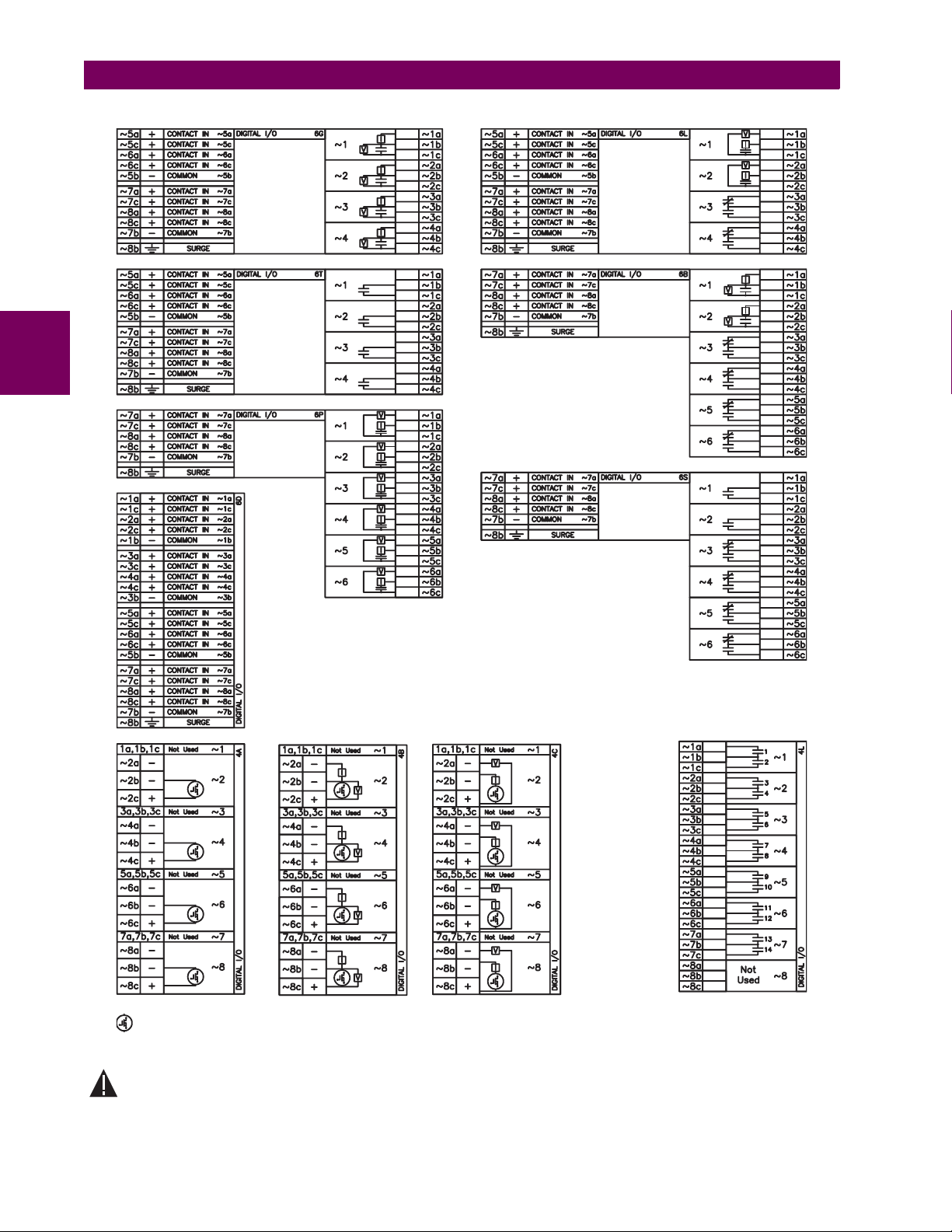
3
3.2 WIRING 3 HARDWARE
– MOSFET Solid State Contact
Figure 3–11: DIGITAL INPUT/OUTPUT MODULE WIRING (2 of 2)
CORRECT POLARITY MUST BE OBSERVED FOR ALL CONTACT INPUT AND SOLID STATE OUTPUT CONNECTIONS FOR PROPER FUNCTIONALITY.
CAUTION
3-12 T35 Transformer Management Relay GE Multilin
827719CY-X2.dwg
Page 49

3 HARDWARE 3.2 WIRING
A dry contact has one side connected to Terminal B3b. This is the positive 48 V DC voltage rail supplied by the power supply module. The other side of the dry contact is connected to the required contact input terminal. Each contact input group
has its own common (negative) terminal which must be connected to the DC negative terminal (B3a) of the power supply
module. When a dry contact closes, a current of 1 to 3 mA will flow through the associated circuit.
A wet contact has one side connected to the positive terminal of an external DC power supply. The other side of this contact
is connected to the required contact input terminal. In addition, the negative side of the external source must be connected
to the relay common (negative) terminal of each contact input group. The maximum external source voltage for this
arrangement is 300 V DC.
The voltage threshold at which each group of four contact inputs will detect a closed contact input is programmable as
17 V DC for 24 V sources, 33 V DC for 48 V sources, 84 V DC for 110 to 125 V sources, and 166 V DC for 250 V sources.
DIGITAL I/O 6B
7a
~
~7c
~
8a
~
8c
~
7b
~
8b
1bB
1a
B
2b
B
3a -
B
3b +
B
5b HI+
B
6b LO+
B
6a
B
8a
B
8b
B
+
CONTACT IN 7a
+
CONTACT IN 7c
+
CONTACT IN 8a
+
CONTACT IN 8c
-
COMMON 7b
CRITICAL
FAILURE
48 VDC
OUTPUT
CONTROL
POWER
SURGE
FILTER
SURGE
~
~
~
~
~
24-250V
POWER SUPPLY 1
(Wet)(Dry)
DIGITAL I/O 6B
~
7a
~
7c
~
8a
~
8c
~
7b
~
8b
+
CONTACT IN 7a
+
CONTACT IN 7c
+
CONTACT IN 8a
+
CONTACT IN 8c
-
COMMON 7b
SURGE
827741A4.CDR
~
~
~
~
~
Figure 3–12: DRY AND WET CONTACT INPUT CONNECTIONS
Wherever a tilde “~” symbol appears, substitute with the Slot Position of the module.
NOTE
Contact outputs may be ordered as Form-A or Form-C. The Form A contacts may be connected for external circuit supervision. These contacts are provided with voltage and current monitoring circuits used to detect the loss of DC voltage in the
circuit, and the presence of DC current flowing through the contacts when the Form-A contact closes. If enabled, the current monitoring can be used as a seal-in signal to ensure that the Form-A contact does not attempt to break the energized
inductive coil circuit and weld the output contacts.
There is no provision in the relay to detect a DC ground fault on 48 V DC control power external output. We
recommend using an external DC supply.
NOTE
3
GE Multilin T35 Transformer Management Relay 3-13
Page 50
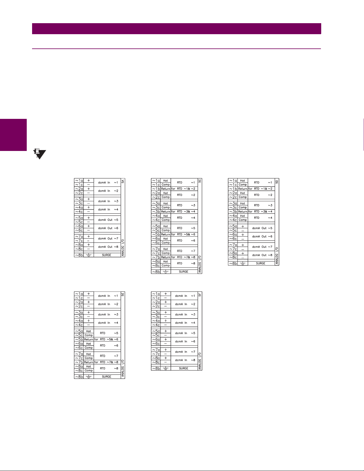
3.2 WIRING 3 HARDWARE
3.2.6 TRANSDUCER INPUTS/OUTPUTS
Transducer input modules can receive input signals from external dcmA output transducers (dcmA In) or resistance temperature detectors (RTD). Hardware and software is provided to receive signals from these external transducers and convert these signals into a digital format for use as required.
Transducer output modules provide DC current outputs in several standard dcmA ranges. Software is provided to configure
virtually any analog quantity used in the relay to drive the analog outputs.
Every transducer input/output module has a total of 24 terminal connections. These connections are arranged as three terminals per row with a total of eight rows. A given row may be used for either inputs or outputs, with terminals in column "a"
having positive polarity and terminals in column "c" having negative polarity. Since an entire row is used for a single input/
output channel, the name of the channel is assigned using the module slot position and row number.
Each module also requires that a connection from an external ground bus be made to Terminal 8b. The current outputs
require a twisted-pair shielded cable, where the shield is grounded at one end only. The figure below illustrates the trans-
3
ducer module types (5A, 5C, 5D, 5E, and 5F) and channel arrangements that may be ordered for the relay.
Wherever a tilde “~” symbol appears, substitute with the Slot Position of the module.
NOTE
827831AB-X1.CDR
Figure 3–13: TRANSDUCER INPUT/OUTPUT MODULE WIRING
3-14 T35 Transformer Management Relay GE Multilin
Page 51
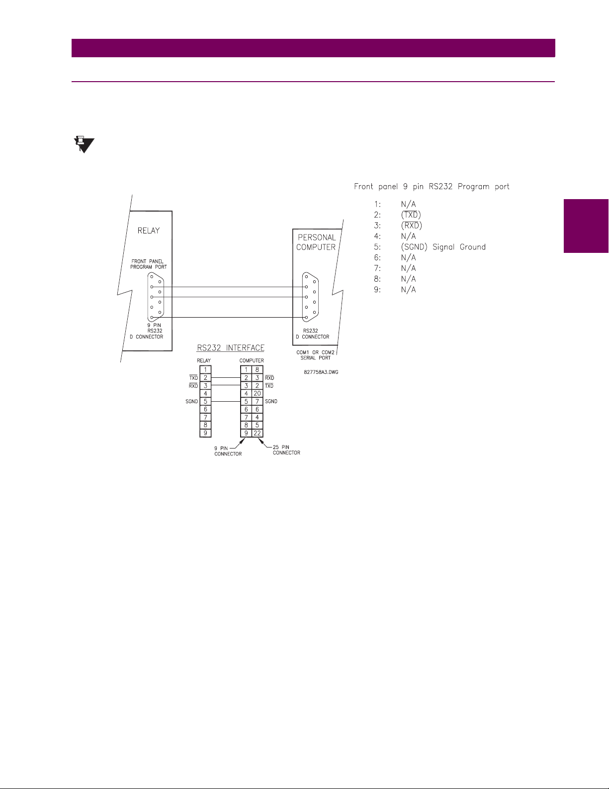
3 HARDWARE 3.2 WIRING
3.2.7 RS232 FACEPLATE PORT
A 9-pin RS232C serial port is located on the relay’s faceplate for programming with a portable (personal) computer. All that
is required to use this interface is a personal computer running the EnerVista UR Setup software provided with the relay.
Cabling for the RS232 port is shown in the following figure for both 9 pin and 25 pin connectors.
The baud rate for this port is fixed at 19200 bps.
NOTE
3
Figure 3–14: RS232 FACEPLATE PORT CONNECTION
GE Multilin T35 Transformer Management Relay 3-15
Page 52

3.2 WIRING 3 HARDWARE
3.2.8 CPU COMMUNICATIONS PORTS
a) OPTIONS
In addition to the RS232 port on the faceplate, the relay provides the user with two additional communication port(s)
depending on the CPU module installed.
The 9E, 9G, and 9H CPU modules do not require a surge ground connection.
NOTE
CPU TYPE COM1 COM2
9E RS485 RS485
9G 10Base-F and 10Base-T RS485
3
9H Redundant 10Base-F RS485
827831AB-X6.DWG
Figure 3–15: CPU MODULE COMMUNICATIONS WIRING
b) RS485 PORTS
RS485 data transmission and reception are accomplished over a single twisted pair with transmit and receive data alternating over the same two wires. Through the use of these port(s), continuous monitoring and control from a remote computer,
SCADA system or PLC is possible.
To minimize errors from noise, the use of shielded twisted pair wire is recommended. Correct polarity must also be
observed. For instance, the relays must be connected with all RS485 “+” terminals connected together, and all RS485 “–”
terminals connected together. The COM terminal should be connected to the common wire inside the shield, when provided. To avoid loop currents, the shield should be grounded at one point only. Each relay should also be daisy chained to
the next one in the link. A maximum of 32 relays can be connected in this manner without exceeding driver capability. For
larger systems, additional serial channels must be added. It is also possible to use commercially available repeaters to
increase the number of relays on a single channel to more than 32. Star or stub connections should be avoided entirely.
Lightning strikes and ground surge currents can cause large momentary voltage differences between remote ends of the
communication link. For this reason, surge protection devices are internally provided at both communication ports. An isolated power supply with an optocoupled data interface also acts to reduce noise coupling. To ensure maximum reliability, all
equipment should have similar transient protection devices installed.
Both ends of the RS485 circuit should also be terminated with an impedance as shown below.
3-16 T35 Transformer Management Relay GE Multilin
Page 53
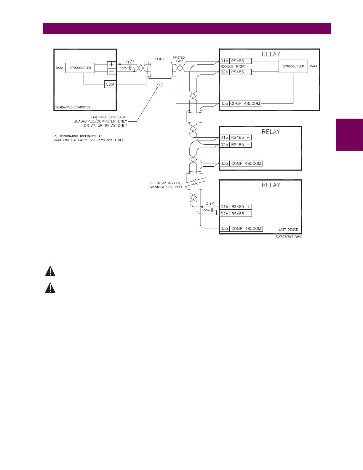
3 HARDWARE 3.2 WIRING
CAUTION
CAUTION
3
Figure 3–16: RS485 SERIAL CONNECTION
c) 10BASE-F FIBER OPTIC PORT
ENSURE THE DUST COVERS ARE INSTALLED WHEN THE FIBER IS NOT IN USE. DIRTY OR SCRATCHED
CONNECTORS CAN LEAD TO HIGH LOSSES ON A FIBER LINK.
OBSERVING ANY FIBER TRANSMITTER OUTPUT MAY CAUSE INJURY TO THE EYE.
The fiber optic communication ports allow for fast and efficient communications between relays at 10 Mbps. Optical fiber
may be connected to the relay supporting a wavelength of 820 nanometers in multimode. Optical fiber is only available for
CPU types 9G and 9H. The 9H CPU has a 10BaseF transmitter and receiver for optical fiber communications and a second
pair of identical optical fiber transmitter and receiver for redundancy.
The optical fiber sizes supported include 50/125 µm, 62.5/125 µm and 100/140 µm. The fiber optic port is designed such
that the response times will not vary for any core that is 100 µm or less in diameter. For optical power budgeting, splices are
required every 1 km for the transmitter/receiver pair (the ST type connector contributes for a connector loss of 0.2 dB).
When splicing optical fibers, the diameter and numerical aperture of each fiber must be the same. In order to engage or disengage the ST type connector, only a quarter turn of the coupling is required.
GE Multilin T35 Transformer Management Relay 3-17
Page 54

3.2 WIRING 3 HARDWARE
3.2.9 IRIG-B
IRIG-B is a standard time code format that allows stamping of events to be synchronized among connected devices within
1 millisecond. The IRIG time code formats are serial, width-modulated codes which can be either DC level shifted or amplitude modulated (AM). Third party equipment is available for generating the IRIG-B signal; this equipment may use a GPS
satellite system to obtain the time reference so that devices at different geographic locations can also be synchronized.
GPS SATELLITE SYSTEM
RG58/59 COAXIAL CABLE
+
-
TO OTHER DEVICES
(DC-SHIFT ONLY)
RELAY
IRIG-B(+)
4B
IRIG-B(-)
4A
BNC (IN)
BNC (OUT)
3
GPS CONNECTION
OPTIONAL
GENERATOR
(DC SHIFT OR
AMPLITUDE MODULATED
SIGNAL CAN BE USED)
IRIG-B
TIME CODE
Figure 3–17: IRIG-B CONNECTION
The IRIG-B repeater provides an amplified DC-shift IRIG-B signal to other equipment. By using one IRIG-B serial connection, several UR-series relays can be synchronized. The IRIG-B repeater has a bypass function to maintain the time signal
even when a relay in the series is powered down.
RECEIVER
REPEATER
827756A5.CDR
Figure 3–18: IRIG-B REPEATER
3-18 T35 Transformer Management Relay GE Multilin
Page 55
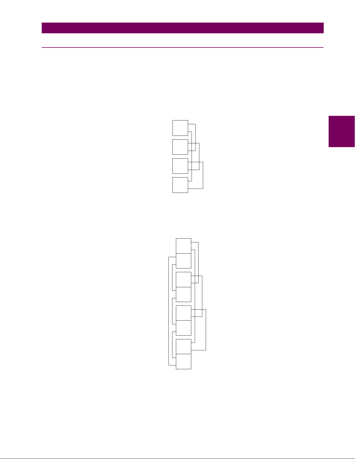
3 HARDWARE 3.3 DIRECT I/O COMMUNICATIONS
3.3DIRECT I/O COMMUNICATIONS 3.3.1 DESCRIPTION
The T35 direct inputs/outputs feature makes use of the Type 7 series of communications modules. These modules are also
used by the L90 Line Differential Relay for inter-relay communications. The direct input/output feature uses the communications channel(s) provided by these modules to exchange digital state information between relays. This feature is available
on all UR-series relay models except for the L90 Line Differential relay.
The communications channels are normally connected in a ring configuration as shown below. The transmitter of one module is connected to the receiver of the next module. The transmitter of this second module is then connected to the receiver
of the next module in the ring. This is continued to form a communications ring. The figure below illustrates a ring of four
UR-series relays with the following connections: UR1-Tx to UR2-Rx, UR2-Tx to UR3-Rx, UR3-Tx to UR4-Rx, and UR4-Tx
to UR1-Rx. A maximum of eight (8) UR-series relays can be connected in a single ring
UR #1
UR #2
UR #3
UR #4
Tx
Rx
Tx
Rx
Tx
Rx
Tx
Rx
842006A1.CDR
Figure 3–19: DIRECT INPUT/OUTPUT SINGLE CHANNEL CONNECTION
The interconnection for dual-channel Type 7 communications modules is shown below. Two channel modules allow for a
redundant ring configuration. That is, two rings can be created to provide an additional independent data path. The required
connections are: UR1-Tx1 to UR2-Rx1, UR2-Tx1 to UR3-Rx1, UR3-Tx1 to UR4-Rx1, and UR4-Tx1 to UR1-Rx1 for the first
ring; and UR1-Tx2 to UR2-Rx2, UR2-Tx2 to UR3-Rx2, UR3-Tx2 to UR4-Rx2, and UR4-Tx2 to UR1-Rx2 for the second
ring.
Tx1
UR #1
UR #2
Rx1
Tx2
Rx2
Tx1
Rx1
Tx2
Rx2
3
Tx1
UR #3
UR #4
Rx1
Tx2
Rx2
Tx1
Rx1
Tx2
Rx2
842007A1.CDR
Figure 3–20: DIRECT INPUT/OUTPUT DUAL CHANNEL CONNECTION
The following diagram shows the connection for three UR-series relays using two independent communication channels.
UR1 and UR3 have single Type 7 communication modules; UR2 has a dual-channel module. The two communication
channels can be of different types, depending on the Type 7 modules used. To allow the direct input/output data to ‘crossover’ from Channel 1 to Channel 2 on UR2, the
DIRECT I/O CHANNEL CROSSOVER setting should be “Enabled” on UR2. This
forces UR2 to forward messages received on Rx1 out Tx2, and messages received on Rx2 out Tx1.
GE Multilin T35 Transformer Management Relay 3-19
Page 56

3.3 DIRECT I/O COMMUNICATIONS 3 HARDWARE
Tx
UR #1
Rx
Channel #1
Tx1
Rx1
UR #2
Tx2
Rx2
Channel #2
Tx
3
UR #3
Rx
842013A1.CDR
Figure 3–21: DIRECT INPUT/OUTPUT SINGLE/DUAL CHANNEL COMBINATION CONNECTION
The interconnection requirements are described in further detail in this section for each specific variation of Type 7 communications module. These modules are listed in the following table. All fiber modules use ST type connectors.
Table 3–3: CHANNEL COMMUNICATION OPTIONS
MODULE SPECIFICATION
2A C37.94SM, 1300 nm, single-mode, ELED, 1 channel single-mode
2B C37.94SM, 1300 nm, single-mode, ELED, 2 channel single-mode
7A 820 nm, multi-mode, LED, 1 channel
7B 1300 nm, multi-mode, LED, 1 channel
7C 1300 nm, single-mode, ELED, 1 channel
7D 1300 nm, single-mode, LASER, 1 channel
7E Channel 1: G.703, Channel 2: 820 nm, multi-mode
7F Channel 1: G.703, Channel 2: 1300 nm, multi-mode
7G Channel 1: G.703, Channel 2: 1300 nm, single-mode ELED
7H 820 nm, multi-mode, LED, 2 channels
7I 1300 nm, multi-mode, LED, 2 channels
7J 1300 nm, single-mode, ELED, 2 channels
7K 1300 nm, single-mode, LASER, 2 channels
7L Channel 1: RS422, Channel: 820 nm, multi-mode, LED
7M Channel 1: RS422, Channel 2: 1300 nm, multi-mode, LED
7N Channel 1: RS422, Channel 2: 1300 nm, single-mode, ELED
7P Channel 1: RS422, Channel 2: 1300 nm, single-mode, LASER
7Q Channel 1: G.703, Channel 2: 1300 nm, single-mode, LASER
7R G.703, 1 channel
7S G.703, 2 channels
7T RS422, 1 channel
7W RS422, 2 channels
72 1550 nm, single-mode, LASER, 1 channel
73 1550 nm, single-mode, LASER, 2 channels
74 Channel 1 - RS422; Channel 2 - 1550 nm, single-mode, LASER
75 Channel 1 - G.703; Channel 2 - 1550 nm, single-mode, LASER
76 IEEE C37.94, 820 nm, multi-mode, LED, 1 channel
77 IEEE C37.94, 820 nm, multi-mode, LED, 2 channels
OBSERVING ANY FIBER TRANSMITTER OUTPUT MAY CAUSE INJURY TO THE EYE.
CAUTION
3-20 T35 Transformer Management Relay GE Multilin
Page 57

3 HARDWARE 3.3 DIRECT I/O COMMUNICATIONS
3.3.2 FIBER: LED AND ELED TRANSMITTERS
The following figure shows the configuration for the 7A, 7B, 7C, 7H, 7I, and 7J fiber-only modules.
Module: 7A / 7B / 7C 7H / 7I / 7J
Connection Location: Slot X Slot X
RX1 RX1
TX1 TX1
RX2
TX2
1 Channel 2 Channels
831719A2.CDR
Figure 3–22: LED AND ELED FIBER MODULES
3.3.3 FIBER-LASER TRANSMITTERS
3
The following figure shows the configuration for the 72, 73, 7D, and 7K fiber-laser module.
Module:
Connection Location:
72/ 7D
Slot X
TX1 TX1
RX1 RX1
1 Channel 2 Channels
73/ 7K
Slot X
TX2
RX2
831720A3.CDR
Figure 3–23: LASER FIBER MODULES
When using a LASER Interface, attenuators may be necessary to ensure that you do not
Optical Input Power to the receiver.
WARNING
exceed Maximum
GE Multilin T35 Transformer Management Relay 3-21
Page 58
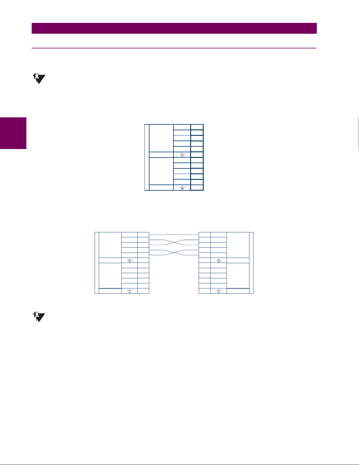
3.3 DIRECT I/O COMMUNICATIONS 3 HARDWARE
3.3.4 G.703 INTERFACE
a) DESCRIPTION
The following figure shows the 64K ITU G.703 co-directional interface configuration.
The G.703 module is fixed at 64 kbps only. The
RATE setting is not applicable to this module.
NOTE
SETTINGS ! PRODUCT SETUP !" DIRECT I/O !" DIRECT I/O DATA
AWG 24 twisted shielded pair is recommended for external connections, with the shield grounded only at one end. Connecting the shield to Pin X1a or X6a grounds the shield since these pins are internally connected to ground. Thus, if
Pin X1a or X6a is used, do not ground at the other end. This interface module is protected by surge suppression devices.
3
7R
G.703
CHANNEL 1
SURGE
G.703
CHANNEL 2
SURGE
COMM.
Shld.
Tx –
Rx –
Tx +
Rx +
Shld.
Tx –
Rx –
Tx +
Rx +
831727A2-X1.CDR
1a
X
1b
X
2a
X
2b
X
3a
X
3b
X
6a
X
6b
X
7a
X
7b
X
8a
X
8b
X
Figure 3–24: G.703 INTERFACE CONFIGURATION
The following figure shows the typical pin interconnection between two G.703 interfaces. For the actual physical arrangement of these pins, see the Rear Terminal Assignments section earlier in this chapter. All pin interconnections are to be
maintained for a connection to a multiplexer.
7R
G.703
CHANNEL 1
SURGE
G.703
CHANNEL 2
COMM.
SURGE
Shld.
Tx -
Rx -
Tx +
Rx +
Shld.
Tx -
Rx -
Tx +
Rx +
1a
X
1b
X
2a
X
2b
X
3a
X
3b
X
6a
X
6b
X
7a
X
7b
X
8a
X
8b
X
Shld.
1a
X
Tx -
1b
X
2a
X
2b
X
3a
X
3b
X
Shld.
6a
X
6b
X
7a
X
7b
X
8a
X
8b
X
Rx -
Tx +
Rx +
Tx -
Rx -
Tx +
Rx +
G.703
CHANNEL 1
SURGE
G.703
CHANNEL 2
SURGE
831727A2.CDR
7R
COMM.
Figure 3–25: TYPICAL PIN INTERCONNECTION BETWEEN TWO G.703 INTERFACES
Pin nomenclature may differ from one manufacturer to another. Therefore, it is not uncommon to see
pinouts numbered TxA, TxB, RxA and RxB. In such cases, it can be assumed that “A” is equivalent to “+”
NOTE
and “B” is equivalent to “–”.
b) G.703 SELECTION SWITCH PROCEDURES
1. Remove the G.703 module (7R or 7S):
The ejector/inserter clips located at the top and at the bottom of each module, must be pulled simultaneously in order
to release the module for removal. Before performing this action, control power must be removed from the relay.
The original location of the module should be recorded to help ensure that the same or replacement module is inserted
into the correct slot.
2. Remove the module cover screw.
3. Remove the top cover by sliding it towards the rear and then lift it upwards.
4. Set the Timing Selection Switches (Channel 1, Channel 2) to the desired timing modes.
5. Replace the top cover and the cover screw.
3-22 T35 Transformer Management Relay GE Multilin
Page 59

3 HARDWARE 3.3 DIRECT I/O COMMUNICATIONS
6. Re-insert the G.703 module Take care to ensure that the correct module type is inserted into the correct slot position.
The ejector/inserter clips located at the top and at the bottom of each module must be in the disengaged position as
the module is smoothly inserted into the slot. Once the clips have cleared the raised edge of the chassis, engage the
clips simultaneously. When the clips have locked into position, the module will be fully inserted.
3
Figure 3–26: G.703 TIMING SELECTION SWITCH SETTING
Table 3–4: G.703 TIMING SELECTIONS
SWITCHES FUNCTION
S1 OFF → Octet Timing Disabled
S5 and S6 S5 = OFF and S6 = OFF → Loop Timing Mode
c) OCTET TIMING (SWITCH S1)
If Octet Timing is enabled (ON), this 8 kHz signal will be asserted during the violation of Bit 8 (LSB) necessary for connecting to higher order systems. When T35s are connected back to back, Octet Timing should be disabled (OFF).
d) TIMING MODES (SWITCHES S5 AND S6)
• Internal Timing Mode: The system clock generated internally. Therefore, the G.703 timing selection should be in the
Internal Timing Mode for back-to-back (UR-to-UR) connections. For Back to Back Connections, set for Octet Timing
(S1 = OFF) and Timing Mode = Internal Timing (S5 = ON and S6 = OFF).
• Loop Timing Mode: The system clock is derived from the received line signal. Therefore, the G.703 timing selection
should be in Loop Timing Mode for connections to higher order systems. For connection to a higher order system (URto-multiplexer, factory defaults), set to Octet Timing (S1 = ON) and set Timing Mode = Loop Timing (S5 = OFF and S6
= OFF).
ON → Octet Timing 8 kHz
S5 = ON and S6 = OFF → Internal Timing Mode
S5 = OFF and S6 = ON → Minimum Remote Loopback Mode
S5 = ON and S6 = ON → Dual Loopback Mode
GE Multilin T35 Transformer Management Relay 3-23
Page 60
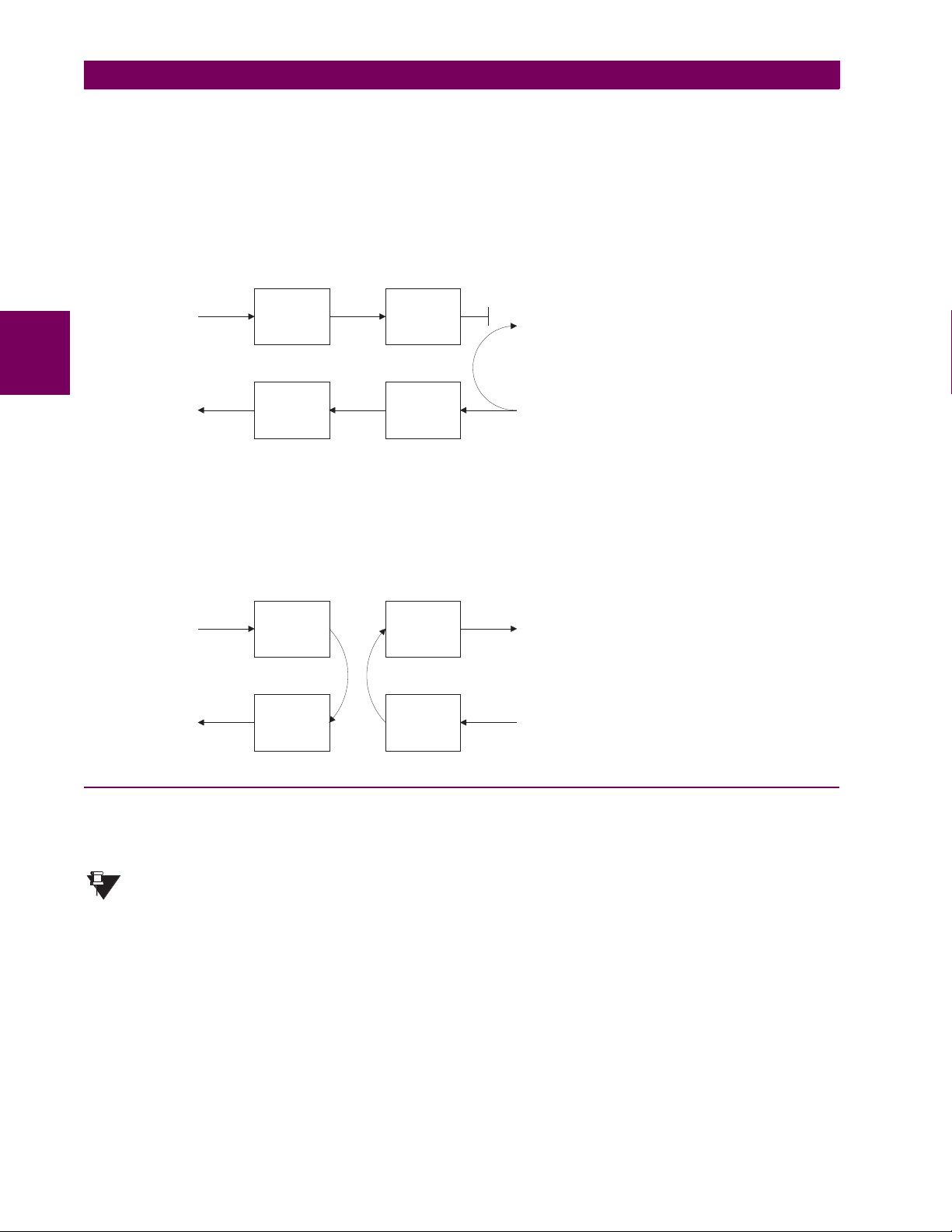
3.3 DIRECT I/O COMMUNICATIONS 3 HARDWARE
e) TEST MODES (SWITCHES S5 AND S6)
MINIMUM REMOTE LOOPBACK MODE:
In Minimum Remote Loopback mode, the multiplexer is enabled to return the data from the external interface without any
processing to assist in diagnosing G.703 Line Side problems irrespective of clock rate. Data enters from the G.703 inputs,
passes through the data stabilization latch which also restores the proper signal polarity, passes through the multiplexer
and then returns to the transmitter. The Differential Received Data is processed and passed to the G.703 Transmitter module after which point the data is discarded. The G.703 Receiver module is fully functional and continues to process data and
passes it to the Differential Manchester Transmitter module. Since timing is returned as it is received, the timing source is
expected to be from the G.703 line side of the interface.
DMR = Differential Manchester Receiver
DMX = Differential Manchester Transmitter
G7X = G.703 Transmitter
G7R = G.703 Receiver
3
DMR
DMX
G7X
G7R
DUAL LOOPBACK MODE:
In Dual Loopback Mode, the multiplexers are active and the functions of the circuit are divided into two with each Receiver/
Transmitter pair linked together to deconstruct and then reconstruct their respective signals. Differential Manchester data
enters the Differential Manchester Receiver module and then is returned to the Differential Manchester Transmitter module.
Likewise, G.703 data enters the G.703 Receiver module and is passed through to the G.703 Transmitter module to be
returned as G.703 data. Because of the complete split in the communications path and because, in each case, the clocks
are extracted and reconstructed with the outgoing data, in this mode there must be two independent sources of timing. One
source lies on the G.703 line side of the interface while the other lies on the Differential Manchester side of the interface.
DMR
DMX
G7X
G7R
DMR = Differential Manchester Receiver
DMX = Differential Manchester Transmitter
G7X = G.703 Transmitter
G7R = G.703 Receiver
3.3.5 RS422 INTERFACE
a) DESCRIPTION
The following figure shows the RS422 2-terminal interface configuration at 64 kbps. AWG 24 twisted shielded pair is recommended for external connections. This interface module is protected by surge suppression devices which optically isolated.
The RS422 module is fixed at 64 kbps only. The
RATE
NOTE
setting is not applicable to this module.
SETTINGS ! PRODUCT SETUP !" DIRECT I/O !" DIRECT I/O DATA
SHIELD TERMINATION
The shield pins (6a and 7b) are internally connected to the ground pin (8a). Proper shield termination is as follows:
Site 1: Terminate shield to pins 6a and/or 7b; Site 2: Terminate shield to ‘COM’ pin 2b.
3-24 T35 Transformer Management Relay GE Multilin
Page 61
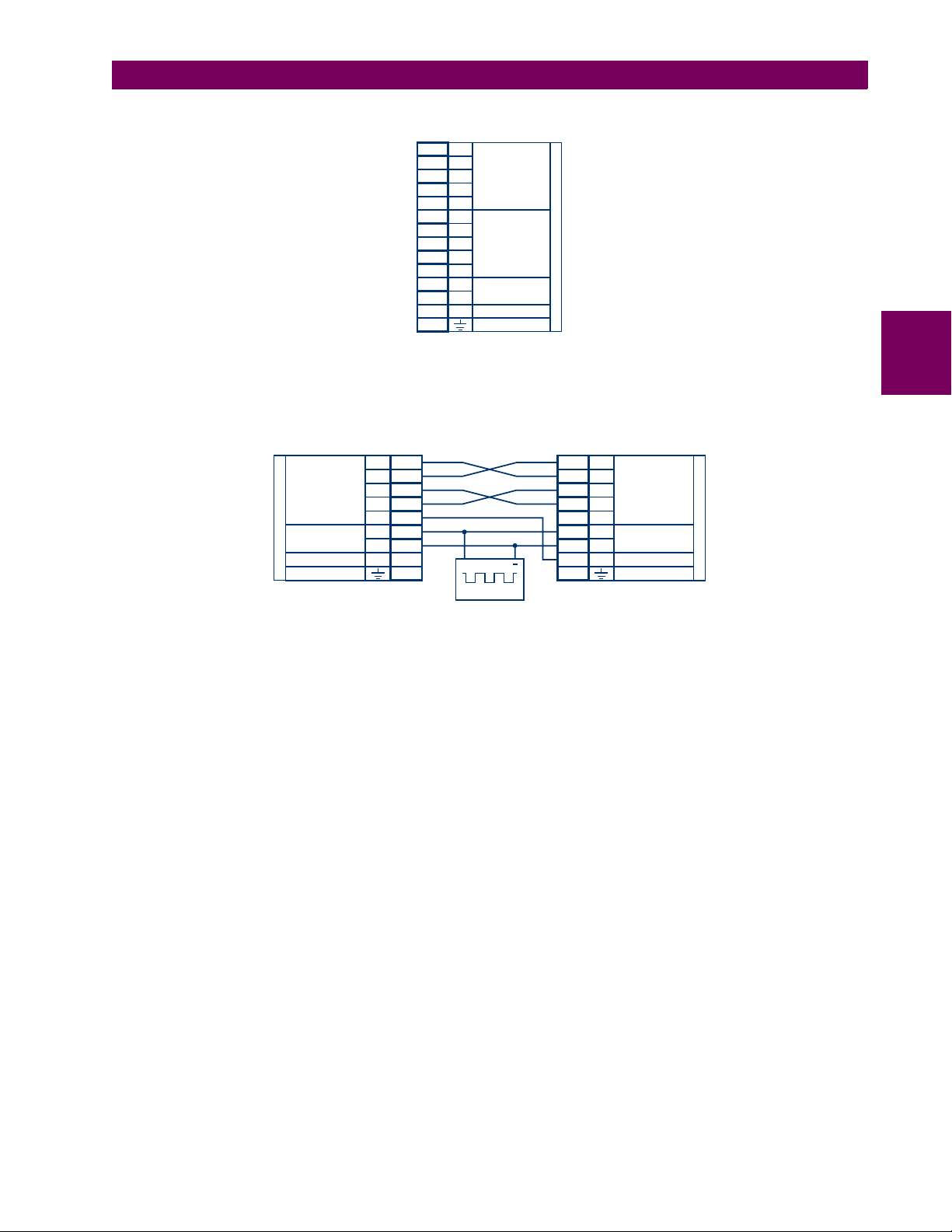
3 HARDWARE 3.3 DIRECT I/O COMMUNICATIONS
The clock terminating impedance should match the impedance of the line.
Tx -
3b
W
Rx -
W
3a
W
2a
W
4b
W
6a
W
5b
W
5a
W
4a
W
6b
W
7b
W
7a
W
8b
W
2b
W
8a
Tx +
Rx +
Shld.
Tx -
Rx -
Tx +
Rx +
Shld.
+
-
com
RS422
CHANNEL 1
RS422
CHANNEL 2
CLOCK
SURGE
RS422.CDR
p/o 827831A6.CDR
W7W
Figure 3–27: RS422 INTERFACE CONFIGURATION
The following figure shows the typical pin interconnection between two RS422 interfaces. All pin interconnections are to be
maintained for a connection to a multiplexer.
3
7T
RS422
CHANNEL 1
CLOCK
SURGE
Tx -
Rx -
Tx +
Rx +
Shld.
+
com
3b
W
W
3a
W
2a
W
4b
W
6a
W
7a
-
W
8b
W
2b
W
8a
+
64 KHz
Tx -
3b
W
Rx -
W
3a
Tx +
W
2a
Rx +
W
4b
W
6a
Shld.
W
7a
W
8b
com
W
2b
W
8a
+
-
RS422
CHANNEL 1
CLOCK
SURGE
831728A3.CDR
7T
Figure 3–28: TYPICAL PIN INTERCONNECTION BETWEEN TWO RS422 INTERFACES
b) TWO CHANNEL APPLICATIONS VIA MULTIPLEXERS
The RS422 Interface may be used for ‘1 channel’ or ‘2 channel’ applications over SONET/SDH and/or Multiplexed systems.
When used in 1 channel applications, the RS422 interface links to higher order systems in a typical fashion observing Tx,
Rx, and Send Timing connections. However, when used in 2 channel applications, certain criteria have to be followed due
to the fact that there is 1 clock input for the two RS422 channels. The system will function correctly if the following connections are observed and your Data Module has a feature called Terminal Timing. Terminal Timing is a common feature to
most Synchronous Data Units that allows the module to accept timing from an external source. Using the Terminal Timing
feature, 2 channel applications can be achieved if these connections are followed: The Send Timing outputs from the Multiplexer - Data Module 1, will connect to the Clock inputs of the UR–RS422 interface in the usual fashion. In addition, the
Send Timing outputs of Data Module 1 will also be paralleled to the Terminal Timing inputs of Data Module 2. By using this
configuration the timing for both Data Modules and both UR–RS422 channels will be derived from a single clock source. As
a result, data sampling for both of the UR–RS422 channels will be synchronized via the Send Timing leads on Data Module
1 as shown in the following figure. If the Terminal Timing feature is not available or this type of connection is not desired, the
G.703 interface is a viable option that does not impose timing restrictions.
GE Multilin T35 Transformer Management Relay 3-25
Page 62
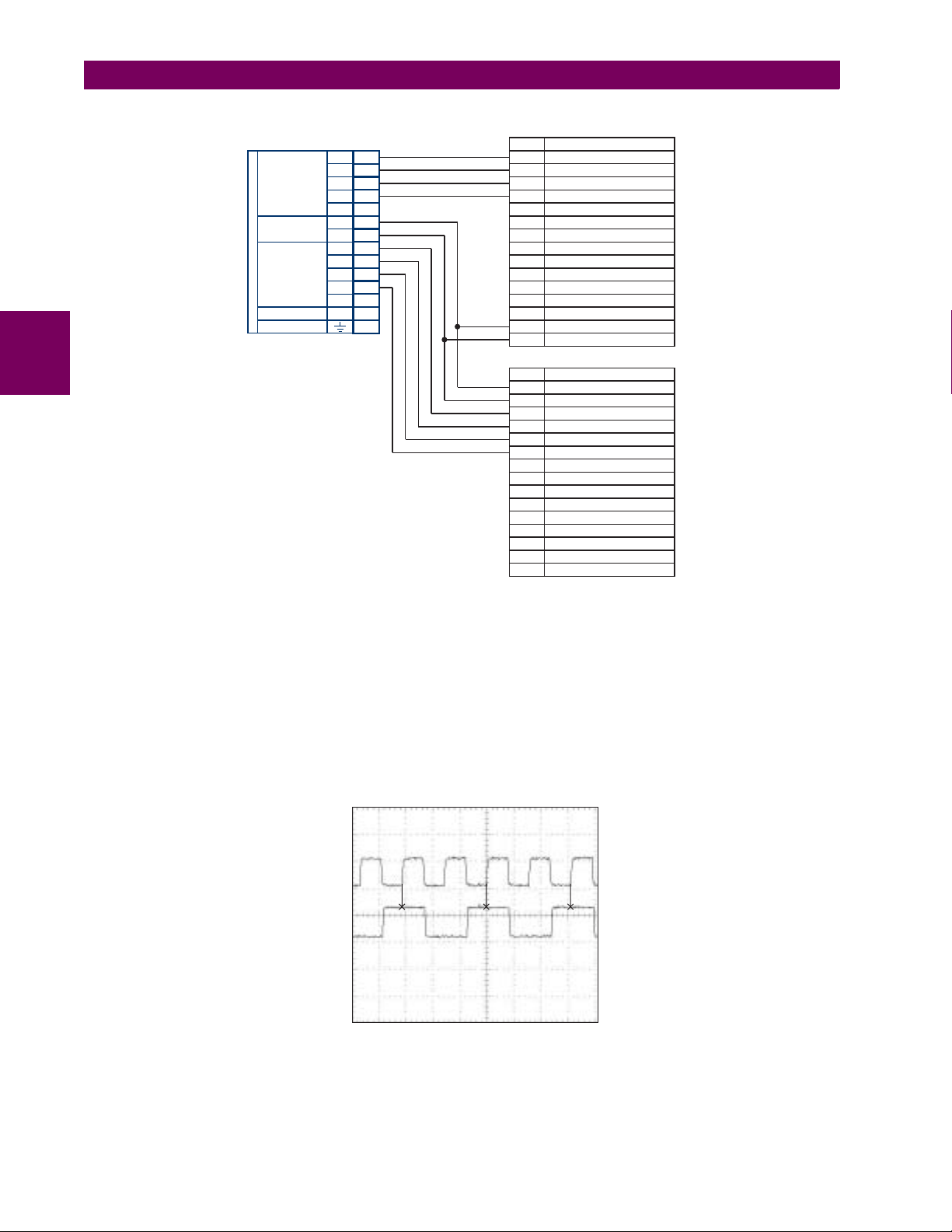
3.3 DIRECT I/O COMMUNICATIONS 3 HARDWARE
3
7W
RS422
CHANNEL 1
CLOCK
RS422
CHANNEL 2
SURGE
L90 COMM.
Tx1(+)
Tx1(-)
Rx1(+)
Rx1(-)
Shld.
+
-
Tx2(+)
Tx2(-)
Rx2(+)
Rx2(-)
Shld.
com
Data Module 1
2a
W
W
3b
W
4b
W
3a
W
6a
7a
W
8b
W
W
4a
W
5b
W
6b
W
5a
7b
W
2b
W
8a
W
Pin No.
Data Module 2
Pin No.
Signal Name
SD(A) - Send Data
SD(B) - Send Data
RD(A) - Received Data
RD(B) - Received Data
RS(A) - Request to Send (RTS)
RS(B) - Request to Send (RTS)
RT(A) - Receive Timing
RT(B) - Receive Timing
CS(A) - Clear To Send
CS(B) - Clear To Send
Local Loopback
Remote Loopback
Signal Ground
ST(A) - Send Timing
ST(B) - Send Timing
Signal Name
TT(A) - Terminal Timing
TT(B) - Terminal Timing
SD(A) - Sand Data
SD(B) - Sand Data
RD(A) - Received Data
RD(B) - Received Data
RS(A) - Request to Send (RTS)
RS(B) - Request to Send (RTS)
CS(A) - Clear To Send
CS(B) - Clear To Send
Local Loopback
Remote Loopback
Signal Ground
ST(A) - Send Timing
ST(B) - Send Timing
831022A2.CDR
Figure 3–29: TIMING CONFIGURATION FOR RS422 TWO-CHANNEL, 3-TERMINAL APPLICATION
Data Module 1 provides timing to the T35 RS422 interface via the ST(A) and ST(B) outputs. Data Module 1 also provides
timing to Data Module 2 TT(A) and TT(B) inputs via the ST(A) and AT(B) outputs. The Data Module pin numbers have been
omitted in the figure above since they may vary depending on the manufacturer.
c) TRANSIT TIMING
The RS422 Interface accepts one clock input for Transmit Timing. It is important that the rising edge of the 64 kHz Transmit
Timing clock of the Multiplexer Interface is sampling the data in the center of the Transmit Data window. Therefore, it is
important to confirm Clock and Data Transitions to ensure Proper System Operation. For example, the following figure
shows the positive edge of the Tx Clock in the center of the Tx Data bit.
Tx Clock
Tx Data
Figure 3–30: CLOCK AND DATA TRANSITIONS
3-26 T35 Transformer Management Relay GE Multilin
Page 63

3 HARDWARE 3.3 DIRECT I/O COMMUNICATIONS
W7E, F, G and Q
Tx2
Rx2
FIBER
CHANNEL 2
X
X
X
X
X
X
Rx +
Shld.
Tx -
Rx -
Tx +
2b
1b
1a
3a
2a
3b
G.703
CHANNEL 1
SURGE
d) RECEIVE TIMING
The RS422 Interface utilizes NRZI-MARK Modulation Code and; therefore, does not rely on an Rx Clock to recapture data.
NRZI-MARK is an edge-type, invertible, self-clocking code.
To recover the Rx Clock from the data-stream, an integrated DPLL (Digital Phase Lock Loop) circuit is utilized. The DPLL is
driven by an internal clock, which is over-sampled 16X, and uses this clock along with the data-stream to generate a data
clock that can be used as the SCC (Serial Communication Controller) receive clock.
3.3.6 RS422 AND FIBER INTERFACE
The following figure shows the combined RS422 plus Fiber interface configuration at 64K baud. The 7L, 7M, 7N, 7P, and 74
modules are used in 2-terminal with a redundant channel or 3-terminal configurations where Channel 1 is employed via the
RS422 interface (possibly with a multiplexer) and Channel 2 via direct fiber.
AWG 24 twisted shielded pair is recommended for external RS422 connections and the shield should be grounded only at
one end. For the direct fiber channel, power budget issues should be addressed properly.
When using a LASER Interface, attenuators may be necessary to ensure that you do not exceed Maximum
Optical Input Power to the receiver.
WARNING
Tx1 -
3b
W
Rx1 -
W
3a
Tx1 +
W
2a
Rx1 +
W
4b
W
6a
Shld.
RS422
CHANNEL 1
3
Tx2
Rx2
W
+
7a
-
W
8b
com
W
2b
W
8a
FIBER
CHANNEL 2
CLOCK
(CHANNEL1)
SURGE
L907LMNP.CDR
P/O 827831A6.CDR
W7L, M, N, P and 74
Figure 3–31: RS422 AND FIBER INTERFACE CONNECTION
Connections shown above are for multiplexers configured as DCE (Data Communications Equipment) units.
3.3.7 G.703 AND FIBER INTERFACE
The figure below shows the combined G.703 plus Fiber interface configuration at 64K baud. The 7E, 7F, 7G, 7Q, and 75
modules are used in configurations where Channel 1 is employed via the G.703 interface (possibly with a multiplexer) and
Channel 2 via direct fiber. AWG 24 twisted shielded pair is recommended for external G.703 connections connecting the
shield to Pin 1A at one end only. For the direct fiber channel, power budget issues should be addressed properly. See previous sections for more details on the G.703 and Fiber interfaces.
When using a LASER Interface, attenuators may be necessary to ensure that you do not exceed Maximum
Optical Input Power to the receiver.
WARNING
Figure 3–32: G.703 AND FIBER INTERFACE CONNECTION
GE Multilin T35 Transformer Management Relay 3-27
Page 64
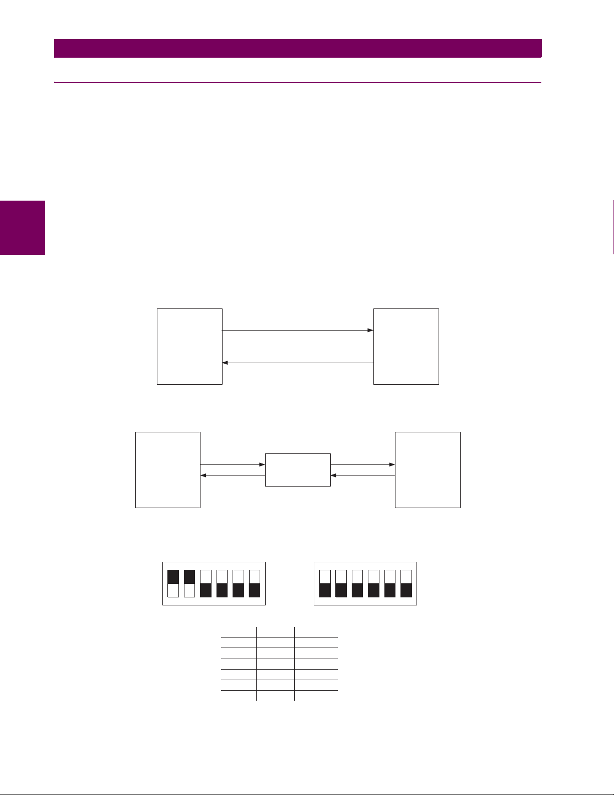
3.3 DIRECT I/O COMMUNICATIONS 3 HARDWARE
3.3.8 IEEE C37.94 INTERFACE
The UR-series IEEE C37.94 communication modules (76 and 77) are designed to interface with IEEE C37.94 compliant
digital multiplexers and/or an IEEE C37.94 compliant interface converter for use with direct input/output applications for
firmware revisions 3.30 and higher. The IEEE C37.94 standard defines a point-to-point optical link for synchronous data
between a multiplexer and a teleprotection device. This data is typically 64 kbps, but the standard provides for speeds up to
64n kbps, where n = 1, 2,…, 12. The UR-series C37.94 communication module is 64 kbps only with n fixed at 1. The frame
is a valid International Telecommunications Union (ITU-T) recommended G.704 pattern from the standpoint of framing and
data rate. The frame is 256 bits and is repeated at a frame rate of 8000 Hz, with a resultant bit rate of 2048 kbps.
The specifications for the module are as follows:
IEEE standard: C37.94 for 1 × 64 kbps optical fiber interface
Fiber optic cable type: 50 mm or 62.5 mm core diameter optical fiber
3
Fiber optic mode: multi-mode
Fiber optic cable length: up to 2 km
Fiber optic connector: type ST
Wavelength: 830 ±40 nm
Connection: as per all fiber optic connections, a Tx to Rx connection is required.
The UR-series C37.94 communication module can be connected directly to any compliant digital multiplexer that supports
the IEEE C37.94 standard as shown below.
IEEE C37.94
Fiber Interface
UR series
relay
up to 2 km
Digital
Multiplexer
IEEE C37.94
compliant
The UR-series C37.94 communication module can be connected to the electrical interface (G.703, RS422, or X.21) of a
non-compliant digital multiplexer via an optical-to-electrical interface converter that supports the IEEE C37.94 standard, as
shown below.
UR series
relay
IEEE C37.94
Fiber Interface
IEEE C37.94
Converter
up to 2 km
RS422
Interface
Digital
Multiplexer
with EIA-422
Interface
The UR-series C37.94 communication module has six (6) switches that are used to set the clock configuration. The functions of these control switches is shown below.
xt
te
xt
Loop Timed
xt
xt
te
te
xt
xt
xt
te
xt
xt
te
te
xt
OFF
xt
xt
ON
Internal Timing Mode
te
te
xt
xt
te
te
xt
te
xt
xt
xt
te
te
xt
xt
ON
xt
te
OFF
xt
153426 153426
Switch Internal Loop Timed
1
2
3
4
5
6
ON OFF
ON OFF
OFF OFF
OFF OFF
OFF OFF
OFF OFF
3-28 T35 Transformer Management Relay GE Multilin
Page 65
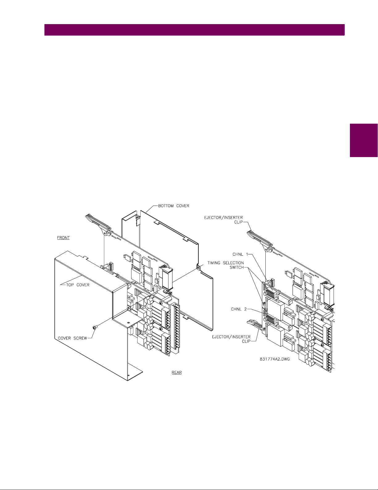
3 HARDWARE 3.3 DIRECT I/O COMMUNICATIONS
For the Internal Timing Mode, the system clock is generated internally. Therefore, the timing switch selection should be
Internal Timing for Relay 1 and Loop Timed for Relay 2. There must be only one timing source configured.
For the Looped Timing Mode, the system clock is derived from the received line signal. Therefore, the timing selection
should be in Loop Timing Mode for connections to higher order systems.
The C37.94 communications module cover removal procedure is as follows:
1. Remove the C37.94 module (76 or 77):
The ejector/inserter clips located at the top and at the bottom of each module, must be pulled simultaneously in order
to release the module for removal. Before performing this action, control power must be removed from the relay.
The original location of the module should be recorded to help ensure that the same or replacement module is inserted
into the correct slot.
2. Remove the module cover screw.
3. Remove the top cover by sliding it towards the rear and then lift it upwards.
4. Set the Timing Selection Switches (Channel 1, Channel 2) to the desired timing modes (see description above).
5. Replace the top cover and the cover screw.
6. Re-insert the C37.94 module Take care to ensure that the correct module type is inserted into the correct slot position. The ejector/inserter clips located at the top and at the bottom of each module must be in the disengaged position
as the module is smoothly inserted into the slot. Once the clips have cleared the raised edge of the chassis, engage
the clips simultaneously. When the clips have locked into position, the module will be fully inserted.
3
Figure 3–33: C37.94 TIMING SELECTION SWITCH SETTING
GE Multilin T35 Transformer Management Relay 3-29
Page 66

3
3.3 DIRECT I/O COMMUNICATIONS 3 HARDWARE
3-30 T35 Transformer Management Relay GE Multilin
Page 67

4 HUMAN INTERFACES 4.1 ENERVISTA UR SETUP SOFTWARE INTERFACE
4 HUMAN INTERFACES 4.1ENERVISTA UR SETUP SOFTWARE INTERFACE 4.1.1 INTRODUCTION
The EnerVista UR Setup software provides a graphical user interface (GUI) as one of two human interfaces to a UR device.
The alternate human interface is implemented via the device’s faceplate keypad and display (see Faceplate Interface section in this chapter).
The EnerVista UR Setup software provides a single facility to configure, monitor, maintain, and trouble-shoot the operation
of relay functions, connected over local or wide area communication networks. It can be used while disconnected (i.e. offline) or connected (i.e. on-line) to a UR device. In off-line mode, settings files can be created for eventual downloading to
the device. In on-line mode, you can communicate with the device in real-time.
The EnerVista UR Setup software, provided with every T35 relay, can be run from any computer supporting Microsoft
®
95, 98, NT, 2000, ME, and XP. This chapter provides a summary of the basic EnerVista UR Setup software interface
dows
features. The EnerVista UR Setup Help File provides details for getting started and using the EnerVista UR Setup software
interface.
4.1.2 CREATING A SITE LIST
To start using the EnerVista UR Setup software, a site definition and device definition must first be created. See the EnerVista UR Setup Help File or refer to the Connecting EnerVista UR Setup with the T35 section in Chapter 1 for details.
4.1.3 ENERVISTA UR SETUP OVERVIEW
a) ENGAGING A DEVICE
The EnerVista UR Setup software may be used in on-line mode (relay connected) to directly communicate with a UR relay.
Communicating relays are organized and grouped by communication interfaces and into sites. Sites may contain any number of relays selected from the UR product series.
Win-
4
b) USING SETTINGS FILES
The EnerVista UR Setup software interface supports three ways of handling changes to relay settings:
• In off-line mode (relay disconnected) to create or edit relay settings files for later download to communicating relays.
• While connected to a communicating relay to directly modify any relay settings via relay data view windows, and then
save the settings to the relay.
• You can create/edit settings files and then write them to the relay while the interface is connected to the relay.
Settings files are organized on the basis of file names assigned by the user. A settings file contains data pertaining to the
following types of relay settings:
• Device Definition
• Product Setup
• System Setup
• FlexLogic™
• Grouped Elements
• Control Elements
• Inputs/Outputs
• Testing
Factory default values are supplied and can be restored after any changes.
c) CREATING AND EDITING FLEXLOGIC™
You can create or edit a FlexLogic™ equation in order to customize the relay. You can subsequently view the automatically
generated logic diagram.
GE Multilin T35 Transformer Management Relay 4-1
Page 68

4.1 ENERVISTA UR SETUP SOFTWARE INTERFACE 4 HUMAN INTERFACES
d) VIEWING ACTUAL VALUES
You can view real-time relay data such as input/output status and measured parameters.
e) VIEWING TRIGGERED EVENTS
While the interface is in either on-line or off-line mode, you can view and analyze data generated by triggered specified
parameters, via one of the following:
• Event Recorder facility: The event recorder captures contextual data associated with the last 1024 events, listed in
chronological order from most recent to oldest.
• Oscillography facility: The oscillography waveform traces and digital states are used to provide a visual display of
power system and relay operation data captured during specific triggered events.
f) FILE SUPPORT
• Execution: Any EnerVista UR Setup file which is double clicked or opened will launch the application, or provide focus
to the already opened application. If the file was a settings file (has a URS extension) which had been removed from
the Settings List tree menu, it will be added back to the Settings List tree menu.
• Drag and Drop: The Site List and Settings List control bar windows are each mutually a drag source and a drop target
for device-order-code-compatible files or individual menu items. Also, the Settings List control bar window and any
4
Windows Explorer directory folder are each mutually a file drag source and drop target.
New files which are dropped into the Settings List window are added to the tree which is automatically sorted alphabetically with respect to settings file names. Files or individual menu items which are dropped in the selected device menu
in the Site List window will automatically be sent to the on-line communicating device.
g) UR FIRMWARE UPGRADES
The firmware of a T35 device can be upgraded, locally or remotely, via the EnerVista UR Setup software. The corresponding instructions are provided by the EnerVista UR Setup Help file under the topic “Upgrading Firmware”.
Modbus addresses assigned to firmware modules, features, settings, and corresponding data items (i.e. default
values, minimum/maximum values, data type, and item size) may change slightly from version to version of firm-
NOTE
ware. The addresses are rearranged when new features are added or existing features are enhanced or modified.
EEPROM DATA ERROR message displayed after upgrading/downgrading the firmware is a resettable, self-test
The
message intended to inform users that the Modbus addresses have changed with the upgraded firmware. This
message does not signal any problems when appearing after firmware upgrades.
4-2 T35 Transformer Management Relay GE Multilin
Page 69

4 HUMAN INTERFACES 4.1 ENERVISTA UR SETUP SOFTWARE INTERFACE
4.1.4 ENERVISTA UR SETUP MAIN WINDOW
The EnerVista UR Setup software main window supports the following primary display components:
a. Title bar which shows the pathname of the active data view
b. Main window menu bar
c. Main window tool bar
d. Site List control bar window
e. Settings List control bar window
f. Device data view window(s), with common tool bar
g. Settings File data view window(s), with common tool bar
h. Workspace area with data view tabs
i. Status bar
4
Figure 4–1: ENERVISTA UR SETUP SOFTWARE MAIN WINDOW
GE Multilin T35 Transformer Management Relay 4-3
Page 70
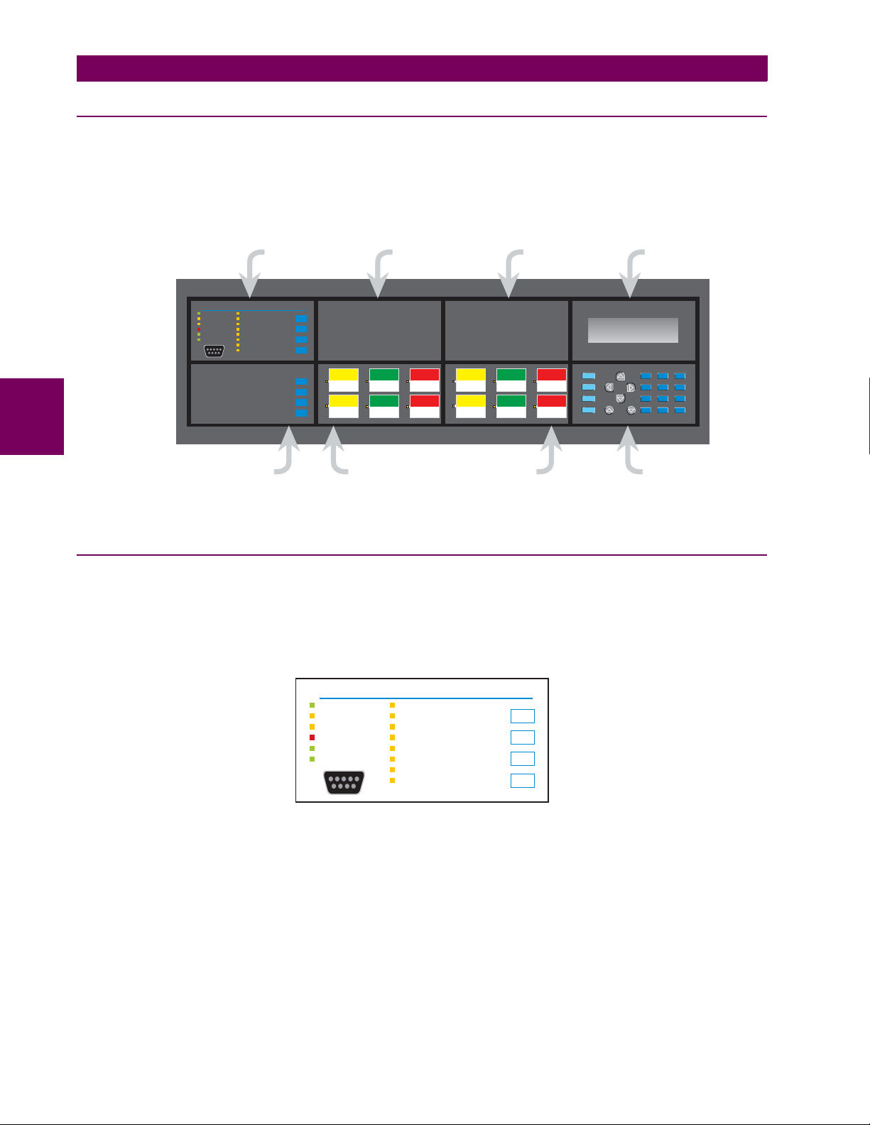
4.2 FACEPLATE INTERFACE 4 HUMAN INTERFACES
4.2FACEPLATE INTERFACE 4.2.1 FACEPLATE
The keypad/display/LED interface is one of two alternate human interfaces supported. The other alternate human interface
is implemented via the EnerVista UR Setup software. The faceplate interface consists of several functional panels.
The faceplate is hinged to allow easy access to the removable modules. There is also a removable dust cover that fits over
the faceplate which must be removed in order to access the keypad panel. The following figure shows the arrangement of
faceplate panels.
4
STATUS
EVENT CAUSE
IN SERVICE
VOLTAGE
TROUBLE
CURRENT
TEST MODE
FREQUENCY
TRIP
OTHER
ALARM
PHASE A
PICKUP
PHASE B
PHASE C
NEUTRAL/GROUND
PUSHBUTTONS 1-7
LED PANEL 1
RESET
USER 1
USER 2
USER 3
USER 4
USER 5
USER 6
USER 7
135
USER LABEL
246
USER LABEL USER LABEL USER LABEL
USER LABEL
USER LABEL
7911
USER LABEL USER LABEL
81012
USER LABEL USER LABEL USER LABEL
USER-PROGRAMMABLE
PUSHBUTTONS 1-12
USER LABEL
MENU
HELP
ESCAPE
ENTER
GE Multilin
MESSAGE
VALUE
DISPLAYLED PANEL 2 LED PANEL 3
7
8
4
5
1
2
.
0
KEYPADCONTROL
827801A5.CDR
Figure 4–2: UR-SERIES HORIZONTAL FACEPLATE PANELS
4.2.2 LED INDICATORS
a) LED PANEL 1
This panel provides several LED indicators, several keys, and a communications port. The RESET key is used to reset any
latched LED indicator or target message, once the condition has been cleared (these latched conditions can also be reset
via the
SETTINGS !" INPUT/OUTPUTS !" RESETTING menu). The USER keys are not used in this unit. The RS232 port is
intended for connection to a portable PC.
9
6
3
+/-
STATUS
IN SERVICE
TROUBLE
TEST MODE
TRIP
ALARM
PICKUP
EVENT CAUSE
VOLTAGE
CURRENT
FREQUENCY
OTHER
PHASE A
PHASE B
PHASE C
NEUTRAL/GROUND
RESET
USER 1
USER 2
USER 3
Figure 4–3: LED PANEL 1
STATUS INDICATORS:
• IN SERVICE: Indicates that control power is applied; all monitored inputs/outputs and internal systems are OK; the
relay has been programmed.
• TROUBLE: Indicates that the relay has detected an internal problem.
• TEST MODE: Indicates that the relay is in test mode.
• TRIP: Indicates that the selected FlexLogic™ operand serving as a Trip switch has operated. This indicator always
latches; the RESET command must be initiated to allow the latch to be reset.
• ALARM: Indicates that the selected FlexLogic™ operand serving as an Alarm switch has operated. This indicator is
never latched.
4-4 T35 Transformer Management Relay GE Multilin
Page 71
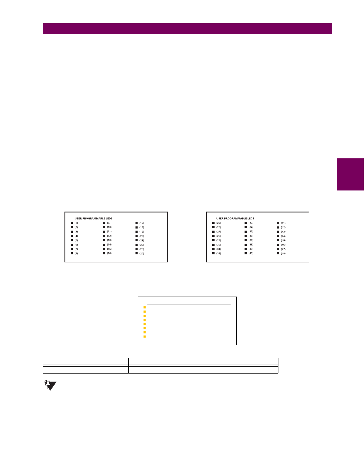
4 HUMAN INTERFACES 4.2 FACEPLATE INTERFACE
• PICKUP: Indicates that an element is picked up. This indicator is never latched.
EVENT CAUSE INDICATORS:
These indicate the input type that was involved in a condition detected by an element that is operated or has a latched flag
waiting to be reset.
• VOLTAGE: Indicates voltage was involved.
• CURRENT: Indicates current was involved.
• FREQUENCY: Indicates frequency was involved.
• OTHER: Indicates a composite function was involved.
• PHASE A: Indicates Phase A was involved.
• PHASE B: Indicates Phase B was involved.
• PHASE C: Indicates Phase C was involved.
• NEUTRAL/GROUND: Indicates neutral or ground was involved.
b) LED PANELS 2 AND 3
These panels provide 48 amber LED indicators whose operation is controlled by the user. Support for applying a customized label beside every LED is provided.
User customization of LED operation is of maximum benefit in installations where languages other than English are used to
communicate with operators. Refer to the User-Programmable LEDs section in Chapter 5 for the settings used to program
the operation of the LEDs on these panels.
4
Figure 4–4: LED PANELS 2 AND 3 (INDEX TEMPLATE)
c) DEFAULT LABELS FOR LED PANEL 2
SETTINGS IN USE
GROUP 1
GROUP 2
GROUP 3
GROUP 4
GROUP 5
GROUP 6
GROUP 7
GROUP 8
The default labels are meant to represent:
FACEPLATE LABEL FUNCTION
GROUP 1...6 The illuminated GROUP is the active settings group.
Firmware revisions 2.9x and earlier support eight user setting groups; revisions 3.0x and higher support
six setting groups. For convenience of users using earlier firmware revisions, the relay panel shows eight
NOTE
setting groups. Please note that the LEDs, despite their default labels, are fully user-programmable.
GE Multilin T35 Transformer Management Relay 4-5
Page 72
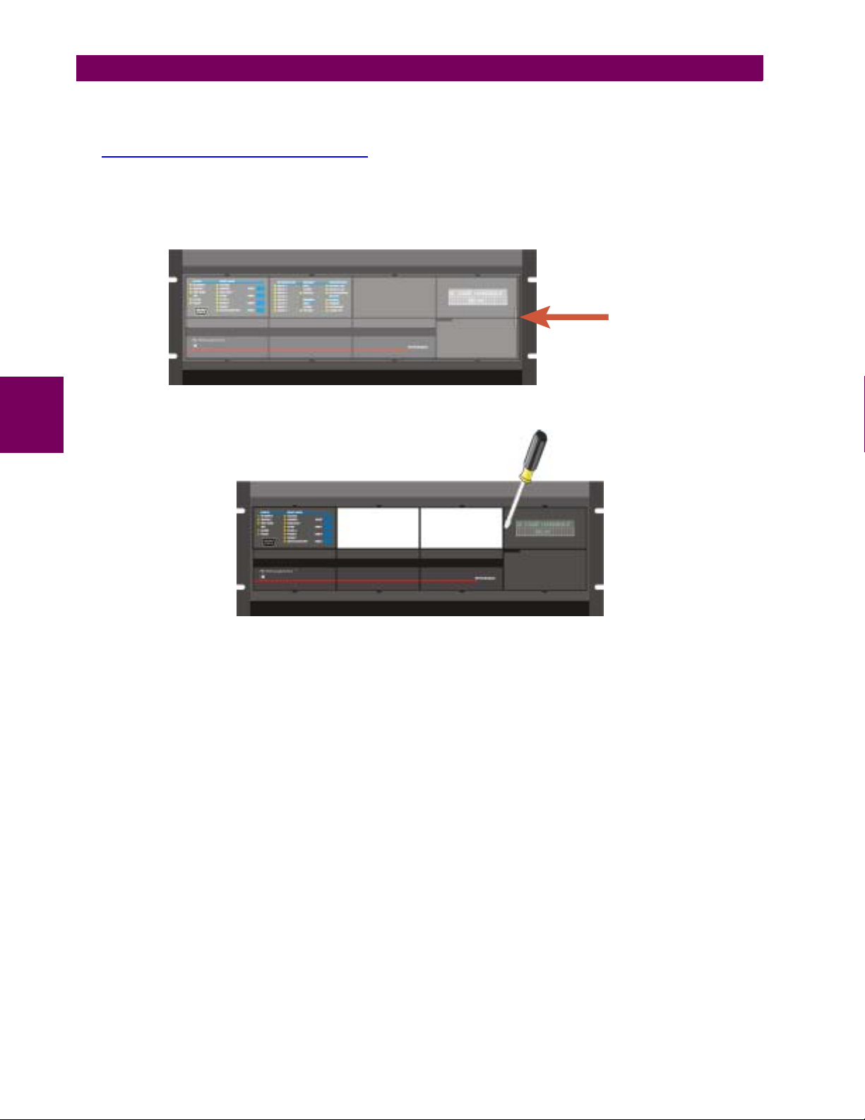
4.2 FACEPLATE INTERFACE 4 HUMAN INTERFACES
d) CUSTOM LABELING OF LEDS
Custom labeling of an LED-only panel is facilitated through a Microsoft Word file available from the following URL:
http://www.GEindustrial.com/multilin/support/ur/
This file provides templates and instructions for creating appropriate labeling for the LED panel. The following procedures
are contained in the downloadable file. The panel templates provide relative LED locations and located example text (x)
edit boxes. The following procedure demonstrates how to install/uninstall the custom panel labeling.
1. Remove the clear Lexan Front Cover (GE Multilin Part Number: 1501-0014).
Push in
and gently lift
up the cover.
2. Pop out the LED Module and/or the Blank Module with a screwdriver as shown below. Be careful not to damage the
4
plastic.
( LED MODULE ) ( BLANK MODULE )
3. Place the left side of the customized module back to the front panel frame, then snap back the right side.
4. Put the clear Lexan Front Cover back into place.
e) CUSTOMIZING THE DISPLAY MODULE
The following items are required to customize the T35 display module:
• Black and white or color printer (color preferred).
• Microsoft Word 97 or later software for editing the template.
• 1 each of: 8.5" x 11" white paper, exacto knife, ruler, custom display module (GE Multilin Part Number: 1516-0069),
and a custom module cover (GE Multilin Part Number: 1502-0015).
1. Open the LED panel customization template with Microsoft Word. Add text in places of the LED x text placeholders on
the template(s). Delete unused place holders as required.
2. When complete, save the Word file to your local PC for future use.
3. Print the template(s) to a local printer.
4. From the printout, cut-out the Background Template from the three windows, using the cropmarks as a guide.
5. Put the Background Template on top of the custom display module (GE Multilin Part Number: 1513-0069) and snap the
clear custom module cover (GE Multilin Part Number: 1502-0015) over it and the templates.
4-6 T35 Transformer Management Relay GE Multilin
Page 73
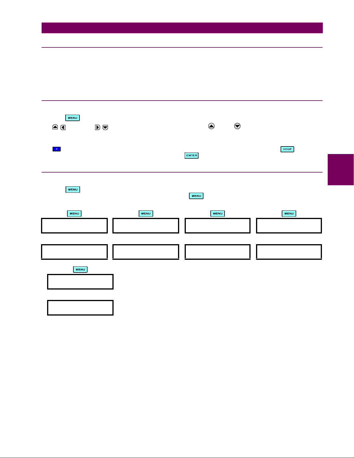
4 HUMAN INTERFACES 4.2 FACEPLATE INTERFACE
4.2.3 DISPLAY
All messages are displayed on a 2 × 20 character vacuum fluorescent display to make them visible under poor lighting conditions. An optional liquid crystal display (LCD) is also available. Messages are displayed in English and do not require the
aid of an instruction manual for deciphering. While the keypad and display are not actively being used, the display will
default to defined messages. Any high priority event driven message will automatically override the default message and
appear on the display.
4.2.4 KEYPAD
Display messages are organized into ‘pages’ under the following headings: Actual Values, Settings, Commands, and Targets. The key navigates through these pages. Each heading page is broken down further into logical subgroups.
The MESSAGE keys navigate through the subgroups. The VALUE keys scroll increment or decrement
numerical setting values when in programming mode. These keys also scroll through alphanumeric values in the text edit
mode. Alternatively, values may also be entered with the numeric keypad.
The key initiates and advance to the next character in text edit mode or enters a decimal point. The key may be
pressed at any time for context sensitive help messages. The key stores altered setting values.
4.2.5 MENUS
a) NAVIGATION
Press the key to select the desired header display page (top-level menu). The header title appears momentarily followed by a header display page menu item. Each press of the key advances through the main heading pages as
illustrated below.
!!!
ACTUAL VALUES SETTINGS COMMANDS TARGETS
""""
## ACTUAL VALUES
## STATUS
## SETTINGS
## PRODUCT SETUP
## COMMANDS
## VIRTUAL INPUTS
No Active
Targets
!
USER DISPLAYS
(when in use)
"
User Display 1
4
GE Multilin T35 Transformer Management Relay 4-7
Page 74
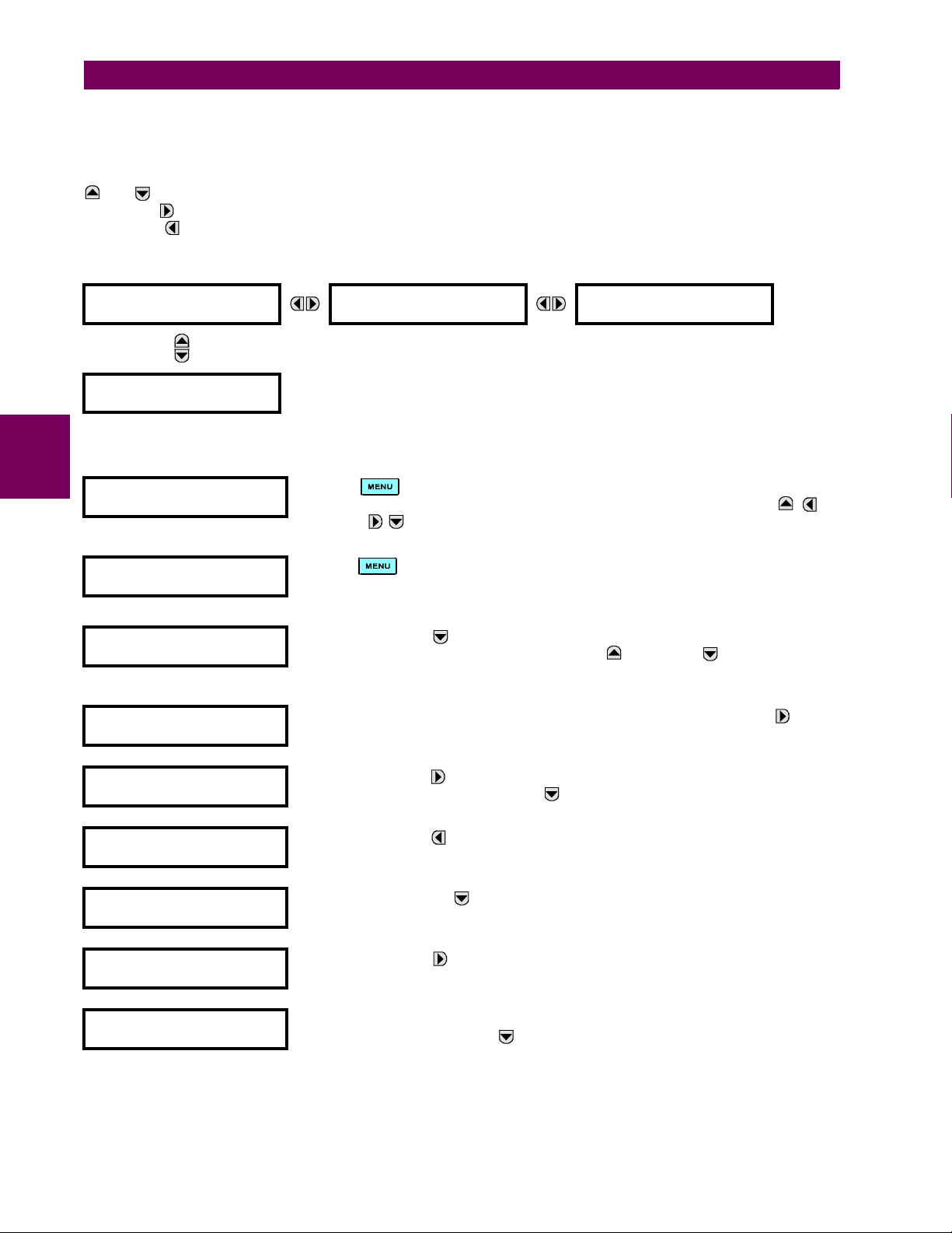
4.2 FACEPLATE INTERFACE 4 HUMAN INTERFACES
b) HIERARCHY
The setting and actual value messages are arranged hierarchically. The header display pages are indicated by double
scroll bar characters (##), while sub-header pages are indicated by single scroll bar characters (#). The header display
pages represent the highest level of the hierarchy and the sub-header display pages fall below this level. The MESSAGE
and keys move within a group of headers, sub-headers, setting values, or actual values. Continually pressing the
MESSAGE key from a header display displays specific information for the header category. Conversely, continually
pressing the MESSAGE key from a setting value or actual value display returns to the header display.
HIGHEST LEVEL LOWEST LEVEL (SETTING VALUE)
## SETTINGS
## PRODUCT SETUP
## SETTINGS
## SYSTEM SETUP
c) EXAMPLE MENU NAVIGATION
4
## ACTUAL VALUES
## STATUS
"
## SETTINGS
## PRODUCT SETUP
"
## SETTINGS
## SYSTEM SETUP
"
# PASSWORD
# SECURITY
"
ACCESS LEVEL:
Restricted
"
# PASSWORD
# SECURITY
"
# DISPLAY
# PROPERTIES
"
FLASH MESSAGE
TIME: 1.0 s
"
DEFAULT MESSAGE
INTENSITY: 25%
# PASSWORD
# SECURITY
Press the key until the header for the first Actual Values page appears. This
page contains system and relay status information. Repeatedly press the
MESSAGE keys to display the other actual value headers.
Press the key until the header for the first page of Settings appears. This page
contains settings to configure the relay.
Press the MESSAGE key to move to the next Settings page. This page contains
settings for System Setup. Repeatedly press the MESSAGE keys to display
the other setting headers and then back to the first Settings page header.
From the Settings page one header (Product Setup), press the MESSAGE key
once to display the first sub-header (Password Security).
Press the MESSAGE key once more and this will display the first setting for Password Security. Pressing the MESSAGE key repeatedly will display the remaining
setting messages for this sub-header.
Press the MESSAGE key once to move back to the first sub-header message.
Pressing the MESSAGE key will display the second setting sub-header associated with the Product Setup header.
Press the MESSAGE key once more and this will display the first setting for Display Properties.
To view the remaining settings associated with the Display Properties subheader,
repeatedly press the MESSAGE key. The last message appears as shown.
ACCESS LEVEL:
Restricted
4-8 T35 Transformer Management Relay GE Multilin
Page 75
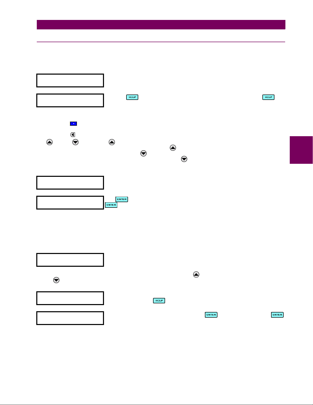
4 HUMAN INTERFACES 4.2 FACEPLATE INTERFACE
4.2.6 CHANGING SETTINGS
a) ENTERING NUMERICAL DATA
Each numerical setting has its own minimum, maximum, and increment value associated with it. These parameters define
what values are acceptable for a setting.
FLASH MESSAGE
TIME: 1.0 s
"
MINIMUM: 0.5
MAXIMUM: 10.0
Two methods of editing and storing a numerical setting value are available.
• 0 to 9 and (decimal point): The relay numeric keypad works the same as that of any electronic calculator. A number is entered one digit at a time. The leftmost digit is entered first and the rightmost digit is entered last. Pressing the
MESSAGE key or pressing the ESCAPE key, returns the original value to the display.
• VAL UE : The VALUE key increments the displayed value by the step value, up to the maximum value
allowed. While at the maximum value, pressing the VALUE key again will allow the setting selection to continue
upward from the minimum value. The VALUE key decrements the displayed value by the step value, down to the
minimum value. While at the minimum value, pressing the VALUE key again will allow the setting selection to continue downward from the maximum value.
FLASH MESSAGE
TIME: 2.5 s
"
NEW SETTING
HAS BEEN STORED
For example, select the
MESSAGE TIME setting.
Press the key to view the minimum and maximum values. Press the key
again to view the next context sensitive help message.
As an example, set the flash message time setting to 2.5 seconds. Press the appropriate
numeric keys in the sequence “2 . 5". The display message will change as the digits are
being entered.
Until is pressed, editing changes are not registered by the relay. Therefore, press
to store the new value in memory. This flash message will momentarily appear as
confirmation of the storing process. Numerical values which contain decimal places will
be rounded-off if more decimal place digits are entered than specified by the step value.
SETTINGS ! PRODUCT SETUP !" DISPLAY PROPERTIES ! FLASH
4
b) ENTERING ENUMERATION DATA
Enumeration settings have data values which are part of a set, whose members are explicitly defined by a name. A set is
comprised of two or more members.
ACCESS LEVEL:
Restricted
Enumeration type values are changed using the VALUE keys. The VALUE key displays the next selection while the
VALUE key displays the previous selection.
ACCESS LEVEL:
Setting
"
NEW SETTING
HAS BEEN STORED
c) ENTERING ALPHANUMERIC TEXT
Text settings have data values which are fixed in length, but user-defined in character. They may be comprised of upper
case letters, lower case letters, numerals, and a selection of special characters.
For example, the selections available for ACCESS LEVEL are "Restricted", "Command",
"Setting", and "Factory Service".
If the
ACCESS LEVEL needs to be "Setting", press the VALUE keys until the proper selec-
tion is displayed. Press at any time for the context sensitive help messages.
Changes are not registered by the relay until the key is pressed. Pressing
stores the new value in memory. This flash message momentarily appears as confirmation of the storing process.
GE Multilin T35 Transformer Management Relay 4-9
Page 76

4.2 FACEPLATE INTERFACE 4 HUMAN INTERFACES
There are several places where text messages may be programmed to allow the relay to be customized for specific applications. One example is the Message Scratchpad. Use the following procedure to enter alphanumeric text messages.
For example: to enter the text, “Breaker #1”
1. Press to enter text edit mode.
2. Press the VALUE keys until the character 'B' appears; press to advance the cursor to the next position.
3. Repeat step 2 for the remaining characters: r,e,a,k,e,r, ,#,1.
4. Press to store the text.
5. If you have any problem, press to view context sensitive help. Flash messages will sequentially appear for several seconds each. For the case of a text setting message, pressing displays how to edit and store new values.
d) ACTIVATING THE RELAY
RELAY SETTINGS:
Not Programmed
When the relay is powered up, the Trouble LED will be on, the In Service LED off, and
this message displayed, indicating the relay is in the "Not Programmed" state and is
safeguarding (output relays blocked) against the installation of a relay whose settings
have not been entered. This message remains until the relay is explicitly put in the
4
To change the
RELAY SETTINGS: "Not Programmed" mode to "Programmed", proceed as follows:
"Programmed" state.
1. Press the key until the SETTINGS header flashes momentarily and the SETTINGS PRODUCT SETUP message
appears on the display.
2. Press the MESSAGE key until the PASSWORD SECURITY message appears on the display.
3. Press the MESSAGE key until the INSTALLATION message appears on the display.
4. Press the MESSAGE key until the
RELAY SETTINGS: Not Programmed message is displayed.
SETTINGS
"
## SETTINGS
## PRODUCT SETUP
# PASSWORD
# SECURITY
# DISPLAY
# PROPERTIES
↓
# USER-DEFINABLE
# DISPLAYS
5. After the
# INSTALLATION
#
RELAY SETTINGS: Not Programmed message appears on the display, press the VALUE keys change the
RELAY SETTINGS:
Not Programmed
selection to "Programmed".
6. Press the key.
RELAY SETTINGS:
Not Programmed
RELAY SETTINGS:
Programmed
NEW SETTING
HAS BEEN STORED
7. When the "NEW SETTING HAS BEEN STORED" message appears, the relay will be in "Programmed" state and the
In Service LED will turn on.
4-10 T35 Transformer Management Relay GE Multilin
Page 77
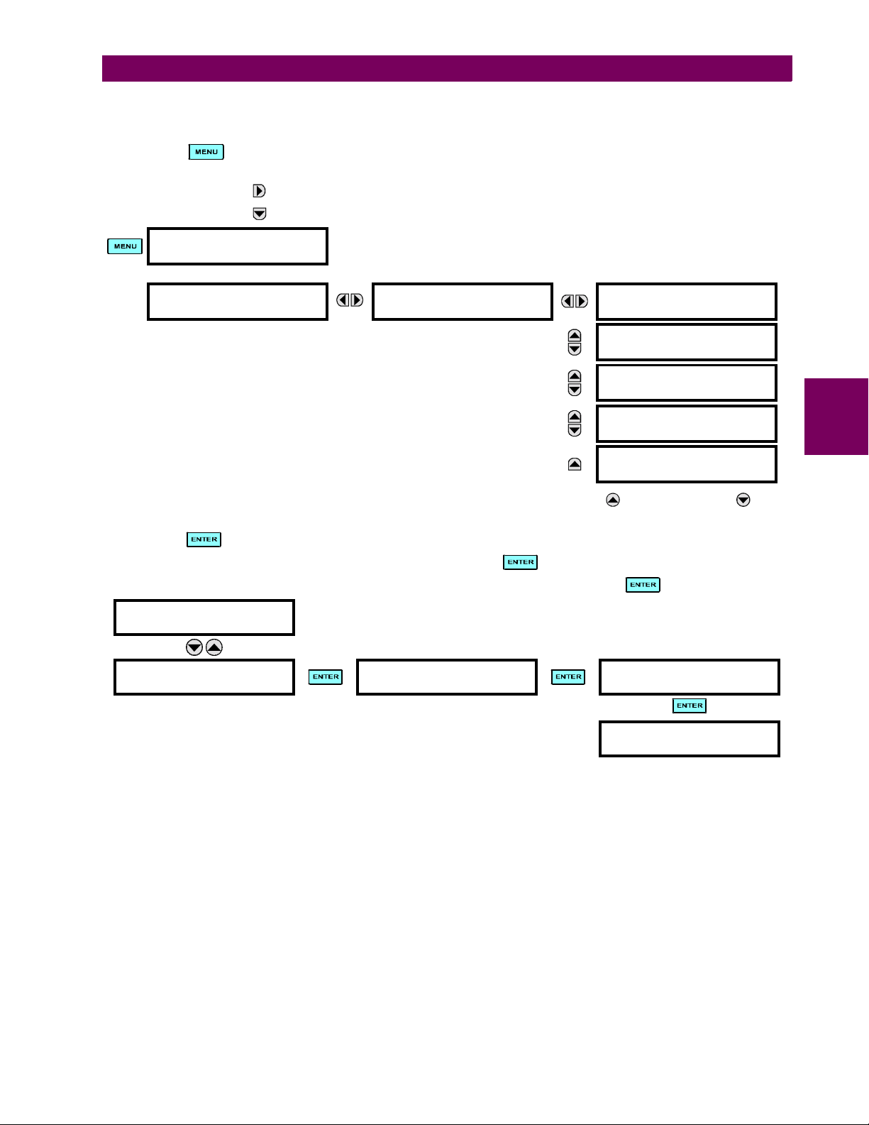
4 HUMAN INTERFACES 4.2 FACEPLATE INTERFACE
e) ENTERING INITIAL PASSWORDS
To enter the initial Setting (or Command) Password, proceed as follows:
1. Press the key until the
appears on the display.
2. Press the MESSAGE key until the ACCESS LEVEL message appears on the display.
3. Press the MESSAGE key until the CHANGE SETTING (or COMMAND) PAS SWOR D message appears on the display.
SETTINGS
"
## SETTINGS
## PRODUCT SETUP
SETTINGS header flashes momentarily and the SETTINGS PRODUCT SETUP message
# PASSWORD
# SECURITY
ACCESS LEVEL:
Restricted
CHANGE COMMAND
PASSWORD: No
CHANGE SETTING
PASSWORD: No
ENCRYPTED COMMAND
PASSWORD: ----------
ENCRYPTED SETTING
PASSWORD: ----------
4. After the
change the selection to “Yes”.
5. Press the key and the display will prompt you to ENTER NEW PASSWORD.
6. Type in a numerical password (up to 10 characters) and press the key.
7. When the VERIFY NEW PASSWORD is displayed, re-type in the same password and press .
CHANGE SETTING
PASSWORD: No
CHANGE SETTING
PASSWORD: Yes
8. When the
active.
f) CHANGING EXISTING PASSWORD
To change an existing password, follow the instructions in the previous section with the following exception. A message will
prompt you to type in the existing password (for each security level) before a new password can be entered.
In the event that a password has been lost (forgotten), submit the corresponding Encrypted Password from the
SECURITY menu to the Factory for decoding.
CHANGE...PASSWORD message appears on the display, press the VALUE key or the VALUE key to
ENTER NEW
PASSWORD: ##########
NEW PASSWORD HAS BEEN STORED message appears, your new Setting (or Command) Password will be
VERIFY NEW
PASSWORD: ##########
NEW PASSWORD
HAS BEEN STORED
PAS SWOR D
4
GE Multilin T35 Transformer Management Relay 4-11
Page 78

4
4.2 FACEPLATE INTERFACE 4 HUMAN INTERFACES
4-12 T35 Transformer Management Relay GE Multilin
Page 79
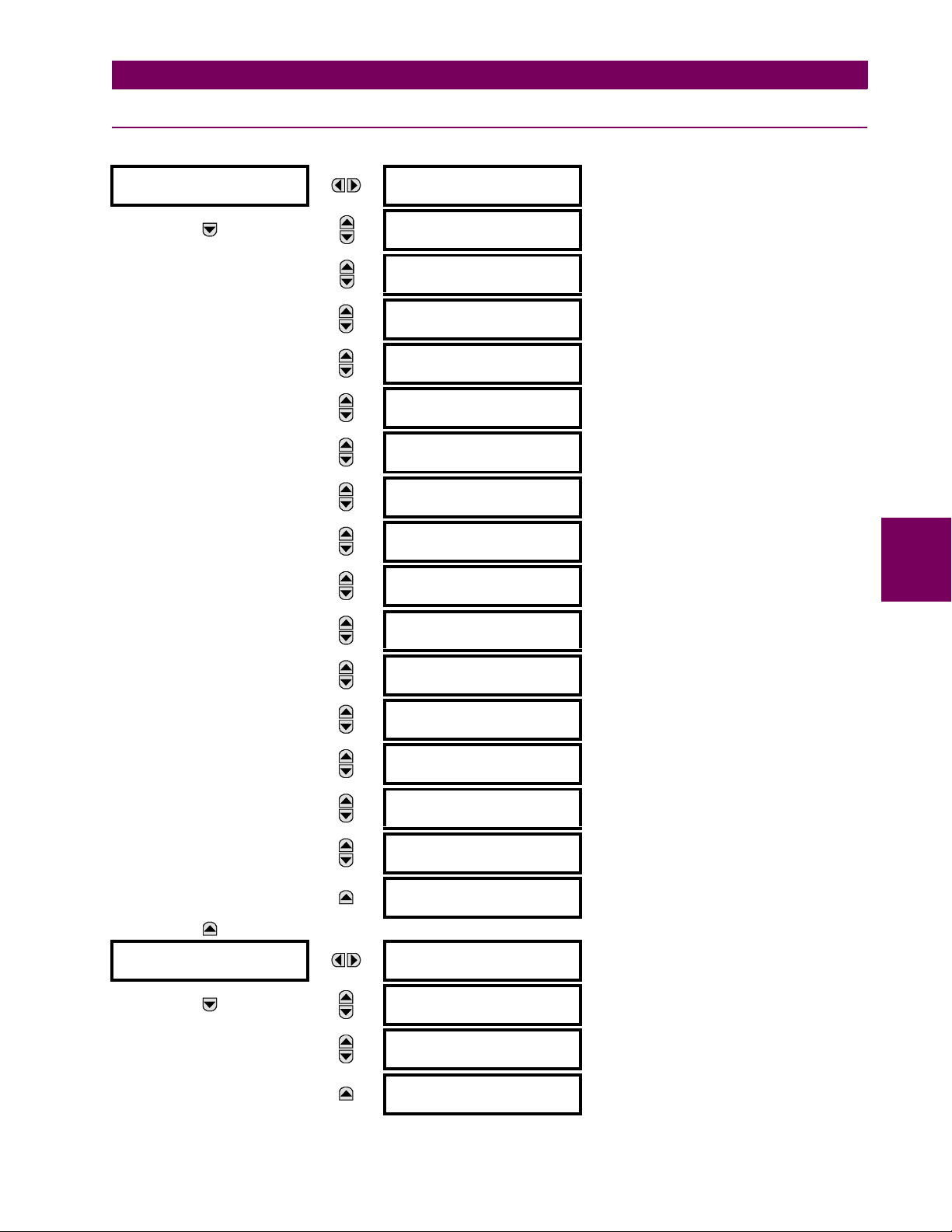
5 SETTINGS 5.1 OVERVIEW
5 SETTINGS 5.1OVERVIEW 5.1.1 SETTINGS MAIN MENU
## SETTINGS ## PRODUCT SETUP
# PASSWORD
# SECURITY
# DISPLAY
# PROPERTIES
# CLEAR RELAY
# RECORDS
# COMMUNICATIONS
#
# MODBUS USER MAP
#
# REAL TIME
# CLOCK
# USER-PROGRAMMABLE
# FAULT REPORT
# OSCILLOGRAPHY
#
# DATA LOGGER
#
# USER-PROGRAMMABLE
# LEDS
# USER-PROGRAMMABLE
# SELF TESTS
See page 5–7.
See page 5–8.
See page 5–10.
See page 5–11.
See page 5–21.
See page 5–21.
See page 5–22.
See page 5–23.
See page 5–24.
5
See page 5–25.
See page 5–28.
## SETTINGS
## SYSTEM SETUP
# CONTROL
# PUSHBUTTONS
# USER-PROGRAMMABLE
# PUSHBUTTONS
# FLEX STATE
# PARAMETERS
# USER-DEFINABLE
# DISPLAYS
# DIRECT I/O
#
# INSTALLATION
#
# AC INPUTS
#
# POWER SYSTEM
#
# SIGNAL SOURCES
#
# TRANSFORMER
#
See page 5–29.
See page 5–30.
See page 5–31.
See page 5–32.
See page 5–34.
See page 5–39.
See page 5–40.
See page 5–42.
See page 5–43.
See page 5–45.
GE Multilin T35 Transformer Management Relay 5-1
Page 80

5.1 OVERVIEW 5 SETTINGS
## SETTINGS
## FLEXLOGIC
## SETTINGS
## GROUPED ELEMENTS
5
## SETTINGS
## CONTROL ELEMENTS
# FLEXCURVES
#
# FLEXLOGIC
# EQUATION EDITOR
# FLEXLOGIC
# TIMERS
# FLEXELEMENTS
#
# NON-VOLATILE
# LATCHES
# SETTING GROUP 1
#
# SETTING GROUP 2
#
↓
↓
# SETTING GROUP 6
#
# SETTING GROUPS
#
See page 5–56.
See page 5–73.
See page 5–73.
See page 5–74.
See page 5–78.
See page 5–79.
See page 5–93.
## SETTINGS
## INPUTS / OUTPUTS
# SELECTOR SWITCH
#
# DIGITAL COUNTERS
#
# MONITORING
# ELEMENTS
# CONTACT INPUTS
#
# VIRTUAL INPUTS
#
# CONTACT OUTPUTS
#
# VIRTUAL OUTPUTS
#
# REMOTE DEVICES
#
# REMOTE INPUTS
#
# REMOTE OUTPUTS
# DNA BIT PAIRS
See page 5–94.
See page 5–99.
See page 5–101.
See page 5–103.
See page 5–105.
See page 5–106.
See page 5–108.
See page 5–109.
See page 5–110.
See page 5–111.
# REMOTE OUTPUTS
# UserSt BIT PAIRS
5-2 T35 Transformer Management Relay GE Multilin
See page 5–111.
Page 81
5 SETTINGS 5.1 OVERVIEW
## SETTINGS
## TRANSDUCER I/O
## SETTINGS
## TESTING
# RESETTING
#
# DIRECT INPUTS
#
# DIRECT OUTPUTS
#
# DCMA INPUTS
#
# RTD INPUTS
#
# DCMA OUTPUTS
#
TEST MODE
FUNCTION: Disabled
TEST MODE INITIATE:
On
# FORCE CONTACT
# INPUTS
# FORCE CONTACT
# OUTPUTS
See page 5–111.
See page 5–112.
See page 5–112.
See page 5–116.
See page 5–117.
See page 5–117.
See page 5–121.
See page 5–121.
See page 5–121.
5
See page 5–122.
5.1.2 INTRODUCTION TO ELEMENTS
In the design of UR relays, the term “element” is used to describe a feature that is based around a comparator. The comparator is provided with an input (or set of inputs) that is tested against a programmed setting (or group of settings) to determine if the input is within the defined range that will set the output to logic 1, also referred to as “setting the flag”. A single
comparator may make multiple tests and provide multiple outputs; for example, the time overcurrent comparator sets a
Pickup flag when the current input is above the setting and sets an Operate flag when the input current has been at a level
above the pickup setting for the time specified by the time-current curve settings. All comparators, except the Digital Element which uses a logic state as the input, use analog parameter actual values as the input.
Elements are arranged into two classes, GROUPED and CONTROL. Each element classed as a GROUPED element is
provided with six alternate sets of settings, in setting groups numbered 1 through 6. The performance of a GROUPED element is defined by the setting group that is active at a given time. The performance of a CONTROL element is independent
of the selected active setting group.
The main characteristics of an element are shown on the element logic diagram. This includes the input(s), settings, fixed
logic, and the output operands generated (abbreviations used on scheme logic diagrams are defined in Appendix F).
Some settings for current and voltage elements are specified in per-unit (pu) calculated quantities:
pu quantity = (actual quantity) / (base quantity)
• For current elements, the ‘base quantity’ is the nominal secondary or primary current of the CT. Where the current
source is the sum of two CTs with different ratios, the ‘base quantity’ will be the common secondary or primary current
to which the sum is scaled (i.e. normalized to the larger of the 2 rated CT inputs). For example, if CT1 = 300 / 5 A and
CT2 = 100 / 5 A, then in order to sum these, CT2 is scaled to the CT1 ratio. In this case, the ‘base quantity’ will be 5 A
secondary or 300 A primary.
• For voltage elements the ‘base quantity’ is the nominal primary voltage of the protected system which corresponds
(based on VT ratio and connection) to secondary VT voltage applied to the relay. For example, on a system with a
13.8 kV nominal primary voltage and with 14400:120 V Delta-connected VTs, the secondary nominal voltage (1 pu)
would be:
GE Multilin T35 Transformer Management Relay 5-3
Page 82

5.1 OVERVIEW 5 SETTINGS
13800
----------------
14400
For Wye-connected VTs, the secondary nominal voltage (1 pu) would be:
120× 115 V=
(EQ 5.1)
13800
----------------
14400
Many settings are common to most elements and are discussed below:
• FUNCTION setting: This setting programs the element to be operational when selected as “Enabled”. The factory
default is “Disabled”. Once programmed to “Enabled”, any element associated with the Function becomes active and
all options become available.
• NAME setting: This setting is used to uniquely identify the element.
• SOURCE setting: This setting is used to select the parameter or set of parameters to be monitored.
• PICKUP setting: For simple elements, this setting is used to program the level of the measured parameter above or
below which the pickup state is established. In more complex elements, a set of settings may be provided to define the
range of the measured parameters which will cause the element to pickup.
• PICKUP DELAY setting: This setting sets a time-delay-on-pickup, or on-delay, for the duration between the Pickup
and Operate output states.
• RESET DELAY setting: This setting is used to set a time-delay-on-dropout, or off-delay, for the duration between the
Operate output state and the return to logic 0 after the input transits outside the defined pickup range.
• BLOCK setting: The default output operand state of all comparators is a logic 0 or “flag not set”. The comparator
remains in this default state until a logic 1 is asserted at the RUN input, allowing the test to be performed. If the RUN
5
input changes to logic 0 at any time, the comparator returns to the default state. The RUN input is used to supervise
the comparator. The BLOCK input is used as one of the inputs to RUN control.
• TAR G E T sett i ng: This setting is used to define the operation of an element target message. When set to Disabled, no
target message or illumination of a faceplate LED indicator is issued upon operation of the element. When set to SelfReset, the target message and LED indication follow the Operate state of the element, and self-resets once the operate element condition clears. When set to Latched, the target message and LED indication will remain visible after the
element output returns to logic 0 - until a RESET command is received by the relay.
• EVENTS setting: This setting is used to control whether the Pickup, Dropout or Operate states are recorded by the
event recorder. When set to Disabled, element pickup, dropout or operate are not recorded as events. When set to
Enabled, events are created for:
(Element) PKP (pickup)
(Element) DPO (dropout)
(Element) OP (operate)
The DPO event is created when the measure and decide comparator output transits from the pickup state (logic 1) to
the dropout state (logic 0). This could happen when the element is in the operate state if the reset delay time is not ‘0’.
120
--------- -
× 66.4 V=
3
(EQ 5.2)
5.1.3 INTRODUCTION TO AC SOURCES
a) BACKGROUND
The T35 may be used on systems with breaker-and-a-half or ring bus configurations. In these applications, each of the two
three-phase sets of individual phase currents (one associated with each breaker) can be used as an input to a breaker failure element. The sum of both breaker phase currents and 3I_0 residual currents may be required for the circuit relaying
and metering functions. For a three-winding transformer application, it may be required to calculate watts and vars for each
of three windings, using voltage from different sets of VTs. These requirements can be satisfied with a single UR, equipped
with sufficient CT and VT input channels, by selecting the parameter to measure. A mechanism is provided to specify the
AC parameter (or group of parameters) used as the input to protection/control comparators and some metering elements.
Selection of the parameter(s) to measure is partially performed by the design of a measuring element or protection/control
comparator by identifying the type of parameter (fundamental frequency phasor, harmonic phasor, symmetrical component,
total waveform RMS magnitude, phase-phase or phase-ground voltage, etc.) to measure. The user completes the process
5-4 T35 Transformer Management Relay GE Multilin
Page 83

5 SETTINGS 5.1 OVERVIEW
R
by selecting the instrument transformer input channels to use and some of the parameters calculated from these channels.
The input parameters available include the summation of currents from multiple input channels. For the summed currents of
phase, 3I_0, and ground current, current from CTs with different ratios are adjusted to a single ratio before summation.
A mechanism called a “Source” configures the routing of CT and VT input channels to measurement sub-systems.
Sources, in the context of UR series relays, refer to the logical grouping of current and voltage signals such that one source
contains all the signals required to measure the load or fault in a particular power apparatus. A given source may contain all
or some of the following signals: three-phase currents, single-phase ground current, three-phase voltages and an auxiliary
voltage from a single VT for checking for synchronism.
To illustrate the concept of Sources, as applied to current inputs only, consider the breaker-and-a-half scheme below. In this
application, the current flows as shown by the arrows. Some current flows through the upper bus bar to some other location
or power equipment, and some current flows into transformer Winding 1. The current into Winding 1 is the phasor sum (or
difference) of the currents in CT1 and CT2 (whether the sum or difference is used depends on the relative polarity of the CT
connections). The same considerations apply to transformer Winding 2. The protection elements require access to the net
current for transformer protection, but some elements may need access to the individual currents from CT1 and CT2.
CT1 CT2
UR
Platform
Through Current
WDG 1
Power
Transformer
WDG 2
CT3 CT4
827791A2.CD
Figure 5–1: BREAKER-AND-A-HALF SCHEME
In conventional analog or electronic relays, the sum of the currents is obtained from an appropriate external connection of
all CTs through which any portion of the current for the element being protected could flow. Auxiliary CTs are required to
perform ratio matching if the ratios of the primary CTs to be summed are not identical. In the UR series of relays, provisions
have been included for all the current signals to be brought to the UR device where grouping, ratio correction and summation are applied internally via configuration settings.
A major advantage of using internal summation is that the individual currents are available to the protection device; for
example, as additional information to calculate a restraint current, or to allow the provision of additional protection features
that operate on the individual currents such as breaker failure.
Given the flexibility of this approach, it becomes necessary to add configuration settings to the platform to allow the user to
select which sets of CT inputs will be added to form the net current into the protected device.
The internal grouping of current and voltage signals forms an internal source. This source can be given a specific name
through the settings, and becomes available to protection and metering elements in the UR platform. Individual names can
be given to each source to help identify them more clearly for later use. For example, in the scheme shown in the above
diagram, the configures one Source to be the sum of CT1 and CT2 and can name this Source as “Wdg 1 Current”.
Once the sources have been configured, the user has them available as selections for the choice of input signal for the protection elements and as metered quantities.
5
b) CT/VT MODULE CONFIGURATION
CT and VT input channels are contained in CT/VT modules. The type of input channel can be phase/neutral/other voltage,
phase/ground current, or sensitive ground current. The CT/VT modules calculate total waveform RMS levels, fundamental
frequency phasors, symmetrical components and harmonics for voltage or current, as allowed by the hardware in each
channel. These modules may calculate other parameters as directed by the CPU module.
GE Multilin T35 Transformer Management Relay 5-5
Page 84

5.1 OVERVIEW 5 SETTINGS
A CT/VT module contains up to eight input channels, numbered 1 through 8. The channel numbering corresponds to the
module terminal numbering 1 through 8 and is arranged as follows: Channels 1, 2, 3 and 4 are always provided as a group,
hereafter called a “bank,” and all four are either current or voltage, as are Channels 5, 6, 7 and 8. Channels 1, 2, 3 and 5, 6,
7 are arranged as phase A, B and C respectively. Channels 4 and 8 are either another current or voltage.
Banks are ordered sequentially from the block of lower-numbered channels to the block of higher-numbered channels, and
from the CT/VT module with the lowest slot position letter to the module with the highest slot position letter, as follows:
INCREASING SLOT POSITION LETTER -->
CT/VT MODULE 1 CT/VT MODULE 2 CT/VT MODULE 3
< bank 1 > < bank 3 > < bank 5 >
< bank 2 > < bank 4 > < bank 6 >
The UR platform allows for a maximum of three sets of three-phase voltages and six sets of three-phase currents. The
result of these restrictions leads to the maximum number of CT/VT modules in a chassis to three. The maximum number of
sources is six. A summary of CT/VT module configurations is shown below.
ITEM MAXIMUM NUMBER
CT/VT Module 3
CT Bank (3 phase channels, 1 ground channel) 12
VT Bank (3 phase channels, 1 auxiliary channel) 6
c) CT/VT INPUT CHANNEL CONFIGURATION
Upon relay startup, configuration settings for every bank of current or voltage input channels in the relay are automatically
generated from the order code. Within each bank, a channel identification label is automatically assigned to each bank of
channels in a given product. The ‘bank’ naming convention is based on the physical location of the channels, required by
5
the user to know how to connect the relay to external circuits. Bank identification consists of the letter designation of the slot
in which the CT/VT module is mounted as the first character, followed by numbers indicating the channel, either 1 or 5.
For three-phase channel sets, the number of the lowest numbered channel identifies the set. For example, F1 represents
the three-phase channel set of F1/F2/F3, where F is the slot letter and 1 is the first channel of the set of three channels.
Upon startup, the CPU configures the settings required to characterize the current and voltage inputs, and will display them
in the appropriate section in the sequence of the banks (as described above) as follows for a maximum configuration: F1,
F5, M1, M5, U1, and U5.
The above section explains how the input channels are identified and configured to the specific application instrument
transformers and the connections of these transformers. The specific parameters to be used by each measuring element
and comparator, and some actual values are controlled by selecting a specific source. The source is a group of current and
voltage input channels selected by the user to facilitate this selection. With this mechanism, a user does not have to make
multiple selections of voltage and current for those elements that need both parameters, such as a distance element or a
watt calculation. It also gathers associated parameters for display purposes.
The basic idea of arranging a source is to select a point on the power system where information is of interest. An application example of the grouping of parameters in a Source is a transformer winding, on which a three phase voltage is measured, and the sum of the currents from CTs on each of two breakers is required to measure the winding current flow.
5-6 T35 Transformer Management Relay GE Multilin
Page 85
5 SETTINGS 5.2 PRODUCT SETUP
5.2PRODUCT SETUP 5.2.1 PASSWORD SECURITY
PATH: SETTINGS ! PRODUCT SETUP ! PASSWORD SECURITY
# PASSWORD
# SECURITY
MESSAGE
MESSAGE
MESSAGE
MESSAGE
ACCESS LEVEL:
Restricted
CHANGE COMMAND
PASSWORD: No
CHANGE SETTING
PASSWORD: No
ENCRYPTED COMMAND
PASSWORD: ----------
ENCRYPTED SETTING
PASSWORD: ----------
Range: Restricted, Command, Setting,
Factory Service (for factory use only)
Range: No, Yes
Range: No, Yes
Range: 0 to 9999999999
Note: ---------- indicates no password
Range: 0 to 9999999999
Note: ---------- indicates no password
Two levels of password security are provided: Command and Setting. Operations under password supervision are:
• COMMAND: changing the state of virtual inputs, clearing the event records, clearing the oscillography records,
changing the date and time, clearing the data logger, user-programmable pushbuttons
• SETTING: changing any setting, test mode operation
The Command and Setting passwords are defaulted to "Null" when the relay is shipped from the factory. When a password
is set to "Null", the password security feature is disabled.
Programming a password code is required to enable each access level. A password consists of 1 to 10 numerical characters. When a CHANGE ... PASSWORD setting is set to "Yes", the following message sequence is invoked:
1. ENTER NEW PASSWORD: ____________
2. VERIFY NEW PASSWORD: ____________
3. NEW PASSWORD HAS BEEN STORED
To gain write access to a "Restricted" setting, set
ACCESS LEVEL to "Setting" and then change the setting, or attempt to
change the setting and follow the prompt to enter the programmed password. If the password is correctly entered, access
will be allowed. If no keys are pressed for longer than 30 minutes or control power is cycled, accessibility will automatically
revert to the "Restricted" level.
If an entered password is lost (or forgotten), consult the factory with the corresponding
ENCRYPTED PASSWORD.
The T35 provides a means to raise an alarm upon failed password entry. Should password verification fail while accessing
a password-protected level of the relay (either settings or commands), the UNAUTHORIZED ACCESS FlexLogic™ operand is
asserted. The operand can be programmed to raise an alarm via contact outputs or communications. This feature can be
used to protect against both unauthorized and accidental access attempts.
The UNAUTHORIZED ACCESS operand is reset with the COMMANDS !" CLEAR RECORDS !" RESET UNAUTHORIZED
ALARMS
command. Therefore, to apply this feature with security, the command level should be password-protected.
The operand does not generate events or targets. If these are required, the operand can be assigned to a digital element
programmed with event logs and/or targets enabled.
If the
SETTING and COMMAND passwords are identical, this one password allows access to both commands
and settings.
NOTE
When EnerVista UR Setup is used to access a particular level, the user will continue to have access to that
level as long as there are open windows in the EnerVista UR Setup software. To re-establish the Password
NOTE
Security feature, all windows must be closed for at least 30 minutes.
5
GE Multilin T35 Transformer Management Relay 5-7
Page 86

5.2 PRODUCT SETUP 5 SETTINGS
5.2.2 DISPLAY PROPERTIES
PATH: SETTINGS ! PRODUCT SETUP !" DISPLAY PROPERTIES
# DISPLAY
# PROPERTIES
MESSAGE
MESSAGE
MESSAGE
MESSAGE
MESSAGE
MESSAGE
MESSAGE
LANGUAGE:
English
FLASH MESSAGE
TIME: 1.0 s
DEFAULT MESSAGE
TIMEOUT: 300 s
DEFAULT MESSAGE
INTENSITY: 25 %
SCREEN SAVER
FEATURE: Disabled
SCREEN SAVER
WAIT TIME: 30 min
CURRENT CUT-OFF
LEVEL: 0.020 pu
VOLTAGE CUT-OFF
LEVEL: 1.0 V
Range: English; English, French; English, Russian;
English, Chinese
(range dependent on order code)
Range: 10 to 900 s in steps of 1
Range: 25%, 50%, 75%, 100%
Visible only if a VFD is installed
Range: Disabled, Enabled
Visible only if an LCD is installed
Range: 1 to 65535 min. in steps of 1
Visible only if an LCD is installed
Range: 0.002 to 0.020 pu in steps of 0.001
Range: 0.002 to 0.020 pu in steps of 0.001
Range: 0.1 to 1.0 V secondary in steps of 0.1
Some relay messaging characteristics can be modified to suit different situations using the display properties settings.
5
• LANGUAGE: This setting selects the language used to display settings, actual values, and targets. The range is
dependent on the order code of the relay.
• FLASH MESSAGE TIME: Flash messages are status, warning, error, or information messages displayed for several
seconds in response to certain key presses during setting programming. These messages override any normal messages. The duration of a flash message on the display can be changed to accommodate different reading rates.
• DEFAULT MESSAGE TIMEOUT: If the keypad is inactive for a period of time, the relay automatically reverts to a
default message. The inactivity time is modified via this setting to ensure messages remain on the screen long enough
during programming or reading of actual values.
• DEFAULT MESSAGE INTENSITY: To extend phosphor life in the vacuum fluorescent display, the brightness can be
attenuated during default message display. During keypad interrogation, the display always operates at full brightness.
• SCREEN SAVER FEATURE and SCREEN SAVER WAIT TIME: These settings are only visible if the T35 has a liquid
crystal display (LCD) and control its backlighting. When the
is turned off after the
DEFAULT MESSAGE TIMEOUT followed by the SCREEN SAVER WAIT TIME, providing that no keys
SCREEN SAVER FEATURE is “Enabled”, the LCD backlighting
have been pressed and no target messages are active. When a keypress occurs or a target becomes active, the LCD
backlighting is turned on.
• CURRENT CUT-OFF LEVEL: This setting modifies the current cut-off threshold. Very low currents (1 to 2% of the
rated value) are very susceptible to noise. Some customers prefer very low currents to display as zero, while others
prefer the current be displayed even when the value reflects noise rather than the actual signal. The T35 applies a cutoff value to the magnitudes and angles of the measured currents. If the magnitude is below the cut-off level, it is substituted with zero. This applies to phase and ground current phasors as well as true RMS values and symmetrical components. The cut-off operation applies to quantities used for metering, protection, and control, as well as those used by
communications protocols. Note that the cut-off level for the sensitive ground input is 10 times lower that the
CUT-OFF LEVEL setting value. Raw current samples available via oscillography are not subject to cut-off.
• VOLTAGE CUT-OFF LEVEL: This setting modifies the voltage cut-off threshold. Very low secondary voltage measure-
ments (at the fractional volt level) can be affected by noise. Some customers prefer these low voltages to be displayed
as zero, while others prefer the voltage to be displayed even when the value reflects noise rather than the actual signal. The T35 applies a cut-off value to the magnitudes and angles of the measured voltages. If the magnitude is below
the cut-off level, it is substituted with zero. This operation applies to phase and auxiliary voltages, and symmetrical
CURRENT
5-8 T35 Transformer Management Relay GE Multilin
Page 87

5 SETTINGS 5.2 PRODUCT SETUP
components. The cut-off operation applies to quantities used for metering, protection, and control, as well as those
used by communications protocols. Raw samples of the voltages available via oscillography are not subject cut-off.
The CURRENT CUT-OFF LEVEL and the VOLTAGE CUT-OFF LEVEL are used to determine the metered power cut-off levels. The
power cut-off level is calculated as shown below. For Delta connections:
3
3-phase power cut-off
CURRENT CUT-OFF LEVEL× VOLTAGE CUT-OFF LEVEL VT primary× CT primary××
----------------------------------------------------------------------------------------------------------------------------------------------------------------------------------------------------------------------------- -=
VT secondary
(EQ 5.3)
For Wye connections:
3-phase power cut-off
per-phase power cut-off
3 CURRENT CUT-OFF LEVEL× VOLTAGE CUT-OFF LEVEL VT primary× CT primary××
------------------------------------------------------------------------------------------------------------------------------------------------------------------------------------------------------------------------- -=
CURRENT CUT-OFF LEVEL VOLTAGE CUT-OFF LEVEL VT primary× CT primary××
----------------------------------------------------------------------------------------------------------------------------------------------------------------------------------------------------------------=
VT secondary
VT secondary
(EQ 5.4)
(EQ 5.5)
where VT primary = VT secondary × VT ratio and CT primary = CT secondary × CT ratio.
For example, given the following settings:
CURRENT CUT-OFF LEVEL: “0.02 pu”
VOLTAGE CUT-OFF LEVEL: “1.0 V”
PHASE CT PRIMARY: “100 A”
PHASE VT SECONDARY: “66.4 V”
PHASE VT RATIO: “208.00 : 1"
PHASE VT CONNECTION: “Delta”.
We have:
CT primary = “100 A”, and
VT primary =
PHASE VT SECONDARY x PHASE VT RATIO = 66.4 V x 208 = 13811.2 V
The power cut-off is therefore:
power cut-off = (CURRENT CUT-OFF LEVEL × VOLTAGE CUT-OFF LEVEL × CT primary × VT primary)/VT secondary
= ( × 0.02 pu × 1.0 V × 100 A × 13811.2 V) / 66.4 V
3
= 720.5 watts
Any calculated power value below this cut-off will not be displayed. As well, the three-phase energy data will not accumulate if the total power from all three phases does not exceed the power cut-off.
Lower the VOLTAGE CUT-OFF LEVEL and CURRENT CUT-OFF LEVEL with care as the relay accepts lower signals
as valid measurements. Unless dictated otherwise by a specific application, the default settings of “0.02
NOTE
pu” for
CURRENT CUT-OFF LEVEL and “1.0 V” for VOLTAGE CUT-OFF LEVEL are recommended.
5
GE Multilin T35 Transformer Management Relay 5-9
Page 88

5.2 PRODUCT SETUP 5 SETTINGS
5.2.3 CLEAR RELAY RECORDS
PATH: SETTINGS ! PRODUCT SETUP !" CLEAR RELAY RECORDS
# CLEAR RELAY
# RECORDS
MESSAGE
MESSAGE
MESSAGE
MESSAGE
MESSAGE
MESSAGE
CLEAR USER REPORTS:
Off
CLEAR EVENT RECORDS:
Off
CLEAR OSCILLOGRAPHY?
No
CLEAR ARC AMPS 1:
Off
CLEAR ARC AMPS 2:
Off
RESET UNAUTH ACCESS:
Off
CLEAR DIR I/O STATS:
Off
Range: FlexLogic™ operand
Range: FlexLogic™ operand
Range: FlexLogic™ operand
Range: FlexLogic™ operand
Range: FlexLogic™ operand
Range: FlexLogic™ operand
Range: FlexLogic™ operand.
Valid only for units with Direct I/O module.
Selected records can be cleared from user-programmable conditions with FlexLogic™ operands. Assigning user-programmable pushbuttons to clear specific records are typical applications for these commands. Since the T35 responds to rising
edges of the configured FlexLogic™ operands, they must be asserted for at least 50 ms to take effect.
Clearing records with user-programmable operands is not protected by the command password. However, user-program-
5
mable pushbuttons are protected by the command password. Thus, if they are used to clear records, the user-programmable pushbuttons can provide extra security if required.
For example, to assign User-Programmable Pushbutton 1 to clear demand records, the following settings should be
applied.
1. Assign the clear demand function to Pushbutton 1 by making the following change in the
SETTINGS ! PRODUCT SETUP
!" CLEAR RELAY RECORDS menu:
CLEAR DEMAND: “PUSHBUTTON 1 ON”
2. Set the properties for User-Programmable Pushbutton 1 by making the following changes in the
SETUP !" USER-PROGRAMMABLE PUSHBUTTONS ! USER PUSHBUTTON 1 menu:
PUSHBUTTON 1 FUNCTION: “Self-reset”
PUSHBTN 1 DROP-OUT TIME: “0.20 s”
SETTINGS ! PRODUCT
5-10 T35 Transformer Management Relay GE Multilin
Page 89
5 SETTINGS 5.2 PRODUCT SETUP
5.2.4 COMMUNICATIONS
a) MAIN MENU
PATH: SETTINGS ! PRODUCT SETUP !" COMMUNICATIONS
# COMMUNICATIONS #
MESSAGE
MESSAGE
MESSAGE
MESSAGE
MESSAGE
MESSAGE
MESSAGE
MESSAGE
MESSAGE
# SERIAL PORTS
#
# NETWORK
#
# MODBUS PROTOCOL
#
# DNP PROTOCOL
#
# IEC 61850 PROTOCOL
#
# WEB SERVER
# HTTP PROTOCOL
# TFTP PROTOCOL
#
# IEC 60870-5-104
# PROTOCOL
# SNTP PROTOCOL
#
# EGD PROTOCOL
#
See below.
See page 5–12.
See page 5–12.
See page 5–13.
See page 5–15.
See page 5–17.
See page 5–18.
See page 5–18.
See page 5–19.
See page 5–19.
5
b) SERIAL PORTS
PATH: SETTINGS ! PRODUCT SETUP !" COMMUNICATIONS ! SERIAL PORTS
# SERIAL PORTS
#
MESSAGE
MESSAGE
MESSAGE
MESSAGE
MESSAGE
RS485 COM1 BAUD
RATE: 19200
RS485 COM1 PARITY:
None
RS485 COM1 RESPONSE
MIN TIME: 0 ms
RS485 COM2 BAUD
RATE: 19200
RS485 COM2 PARITY:
None
RS485 COM2 RESPONSE
MIN TIME: 0 ms
Range: 300, 1200, 2400, 4800, 9600, 14400, 19200,
28800, 33600, 38400, 57600, 115200. Only
active if CPU 9E is ordered.
Range: None, Odd, Even
Only active if CPU Type 9E is ordered
Range: 0 to 1000 ms in steps of 10
Only active if CPU Type 9E is ordered
Range: 300, 1200, 2400, 4800, 9600, 14400, 19200,
28800, 33600, 38400, 57600, 115200
Range: None, Odd, Even
Range: 0 to 1000 ms in steps of 10
The T35 is equipped with up to 3 independent serial communication ports. The faceplate RS232 port is intended for local
use and is fixed at 19200 baud and no parity. The rear COM1 port type is selected when ordering: either an Ethernet or
RS485 port. The rear COM2 port is RS485. The RS485 ports have settings for baud rate and parity. It is important that
these parameters agree with the settings used on the computer or other equipment that is connected to these ports. Any of
these ports may be connected to a computer running EnerVista UR Setup. This software can download and upload setting
files, view measured parameters, and upgrade the relay firmware. A maximum of 32 relays can be daisy-chained and connected to a DCS, PLC or PC using the RS485 ports.
GE Multilin T35 Transformer Management Relay 5-11
Page 90
5.2 PRODUCT SETUP 5 SETTINGS
For each RS485 port, the minimum time before the port will transmit after receiving data from a host can be
set. This feature allows operation with hosts which hold the RS485 transmitter active for some time after
NOTE
each transmission.
c) NETWORK
PATH: SETTINGS ! PRODUCT SETUP !" COMMUNICATIONS !" NETWORK
# NETWORK
#
MESSAGE
MESSAGE
MESSAGE
MESSAGE
IP ADDRESS:
0.0.0.0
SUBNET IP MASK:
0.0.0.0
GATEWAY IP ADDRESS:
0.0.0.0
# OSI NETWORK
# ADDRESS (NSAP)
ETHERNET OPERATION
MODE: Full-Duplex
Range: Standard IP address format
Range: Standard IP address format
Range: Standard IP address format
Range: Press the MESSAGE ! key to enter the OSI
Range: Half-Duplex, Full-Duplex
Only active if CPU Type 9G or 9H is ordered.
Only active if CPU Type 9G or 9H is ordered.
Only active if CPU Type 9G or 9H is ordered.
NETWORK ADDRESS
9G or 9H is ordered.
Only active if CPU Type 9G or 9H is ordered.
. Only active if CPU Type
These messages appear only if the T35 is ordered with an Ethernet card.
The IP addresses are used with the DNP, Modbus/TCP, IEC 61580, IEC 60870-5-104, TFTP, and HTTP protocols. The
NSAP address is used with the IEC 61850 protocol over the OSI (CLNP/TP4) stack only. Each network protocol has a setting for the
TCP/UDP PORT NUMBER. These settings are used only in advanced network configurations and should normally
be left at their default values, but may be changed if required (for example, to allow access to multiple UR-series relays
behind a router). By setting a different
5
TCP/UDP PORT NUMBER for a given protocol on each UR-series relay, the router can
map the relays to the same external IP address. The client software (EnerVista UR Setup, for example) must be configured
to use the correct port number if these settings are used.
When the NSAP address, any TCP/UDP Port Number, or any User Map setting (when used with DNP) is changed,
it will not become active until power to the relay has been cycled (OFF/ON).
NOTE
Do not set more than one protocol to use the same TCP/UDP PORT NUMBER, as this will result in unreliable
WARNING
operation of those protocols.
d) MODBUS PROTOCOL
PATH: SETTINGS ! PRODUCT SETUP !" COMMUNICATIONS !" MODBUS PROTOCOL
# MODBUS PROTOCOL
#
MESSAGE
MODBUS SLAVE
ADDRESS: 254
MODBUS TCP PORT
NUMBER: 502
Range: 1 to 254 in steps of 1
Range: 1 to 65535 in steps of 1
The serial communication ports utilize the Modbus protocol, unless configured for DNP operation (see the DNP Protocol
description below). This allows the EnerVista UR Setup software to be used. The UR operates as a Modbus slave device
only. When using Modbus protocol on the RS232 port, the T35 will respond regardless of the
MODBUS SLAVE ADDRESS pro-
grammed. For the RS485 ports each T35 must have a unique address from 1 to 254. Address 0 is the broadcast address
which all Modbus slave devices listen to. Addresses do not have to be sequential, but no two devices can have the same
address or conflicts resulting in errors will occur. Generally, each device added to the link should use the next higher
address starting at 1. Refer to Appendix B for more information on the Modbus protocol.
5-12 T35 Transformer Management Relay GE Multilin
Page 91
5 SETTINGS 5.2 PRODUCT SETUP
e) DNP PROTOCOL
PATH: SETTINGS ! PRODUCT SETUP !" COMMUNICATIONS !" DNP PROTOCOL
# DNP PROTOCOL
#
MESSAGE
MESSAGE
MESSAGE
MESSAGE
MESSAGE
MESSAGE
MESSAGE
MESSAGE
MESSAGE
MESSAGE
MESSAGE
MESSAGE
MESSAGE
MESSAGE
MESSAGE
MESSAGE
MESSAGE
MESSAGE
MESSAGE
MESSAGE
DNP PORT:
NONE
DNP ADDRESS:
255
# DNP NETWORK
# CLIENT ADDRESSES
DNP TCP/UDP PORT
NUMBER: 20000
DNP UNSOL RESPONSE
FUNCTION: Disabled
DNP UNSOL RESPONSE
TIMEOUT: 5 s
DNP UNSOL RESPONSE
MAX RETRIES: 10
DNP UNSOL RESPONSE
DEST ADDRESS: 1
USER MAP FOR DNP
ANALOGS: Disabled
NUMBER OF SOURCES
IN ANALOG LIST: 1
DNP CURRENT SCALE
FACTOR: 1
DNP VOLTAGE SCALE
FACTOR: 1
DNP POWER SCALE
FACTOR: 1
DNP ENERGY SCALE
FACTOR: 1
DNP OTHER SCALE
FACTOR: 1
DNP CURRENT DEFAULT
DEADBAND: 30000
DNP VOLTAGE DEFAULT
DEADBAND: 30000
DNP POWER DEFAULT
DEADBAND: 30000
DNP ENERGY DEFAULT
DEADBAND: 30000
DNP OTHER DEFAULT
DEADBAND: 30000
DNP TIME SYNC IIN
PERIOD: 1440 min
Range: NONE, COM1 - RS485, COM2 - RS485, FRONT
PANEL - RS232, NETWORK
Range: 0 to 65519 in steps of 1
Range: Press the MESSAGE ! key to enter the DNP
NETWORK CLIENT ADDRESSES
Range: 1 to 65535 in steps of 1
Range: Enabled, Disabled
Range: 0 to 60 s in steps of 1
Range: 1 to 255 in steps of 1
Range: 0 to 65519 in steps of 1
Range: Enabled, Disabled
Range: 1 to 6 in steps of 1
Range: 0.001, 0.01. 0.1, 1, 10, 100, 1000, 10000,
100000
Range: 0.001, 0.01. 0.1, 1, 10, 100, 1000, 10000,
100000
Range: 0.001, 0.01. 0.1, 1, 10, 100, 1000, 10000,
100000
Range: 0.001, 0.01. 0.1, 1, 10, 100, 1000, 10000,
100000
Range: 0.001, 0.01. 0.1, 1, 10, 100, 1000, 10000,
100000
Range: 0 to 65535 in steps of 1
Range: 0 to 65535 in steps of 1
Range: 0 to 65535 in steps of 1
Range: 0 to 65535 in steps of 1
Range: 0 to 65535 in steps of 1
Range: 1 to 10080 min. in steps of 1
5
GE Multilin T35 Transformer Management Relay 5-13
Page 92

5.2 PRODUCT SETUP 5 SETTINGS
5
MESSAGE
MESSAGE
MESSAGE
MESSAGE
MESSAGE
MESSAGE
MESSAGE
MESSAGE
MESSAGE
MESSAGE
MESSAGE
DNP MESSAGE FRAGMENT
SIZE: 240
# DNP BINARY INPUTS
# USER MAP
DNP OBJECT 1
DEFAULT VARIATION: 2
DNP OBJECT 2
DEFAULT VARIATION: 2
DNP OBJECT 20
DEFAULT VARIATION: 1
DNP OBJECT 21
DEFAULT VARIATION: 1
DNP OBJECT 22
DEFAULT VARIATION: 1
DNP OBJECT 23
DEFAULT VARIATION: 2
DNP OBJECT 30
DEFAULT VARIATION: 1
DNP OBJECT 32
DEFAULT VARIATION: 1
DNP NUMBER OF PAIRED
CONTROL POINTS: 0
Range: 30 to 2048 in steps of 1
Range: 1, 2
Range: 1, 2
Range: 1, 2, 5, 6
Range: 1, 2, 9, 10
Range: 1, 2, 5, 6
Range: 1, 2, 5, 6
Range: 1, 2, 3, 4, 5
Range: 1, 2, 3, 4, 5, 7
Range: 0 to 16 in steps of 1
The T35 supports the Distributed Network Protocol (DNP) version 3.0. The T35 can be used as a DNP slave device connected to a single DNP master (usually an RTU or a SCADA master station). Since the T35 maintains one set of DNP data
change buffers and connection information, only one DNP master should actively communicate with the T35 at one time.
DNP PORT setting selects the communications port assigned to the DNP protocol; only a single port can be assigned.
The
Once DNP is assigned to a serial port, the Modbus protocol is disabled on that port. Note that COM1 can be used only in
non-ethernet UR relays. When this setting is set to “Network”, the DNP protocol can be used over either TCP/IP or UDP/IP.
Refer to Appendix E for more information on the DNP protocol. The
DNP ADDRESS setting is the DNP slave address. This
number identifies the T35 on a DNP communications link. Each DNP slave should be assigned a unique address. The DNP
NETWORK CLIENT ADDRESS setting can force the T35 to respond to a maximum of five specific DNP masters.
DNP UNSOL RESPONSE FUNCTION should be “Disabled” for RS485 applications since there is no collision avoidance
The
mechanism. The DNP UNSOL RESPONSE TIMEOUT sets the time the T35 waits for a DNP master to confirm an unsolicited
response. The
DNP UNSOL RESPONSE MAX RETRIES setting determines the number of times the T35 retransmits an unsolic-
ited response without receiving confirmation from the master; a value of “255” allows infinite re-tries. The DNP UNSOL
RESPONSE DEST ADDRESS
is the DNP address to which all unsolicited responses are sent. The IP address to which unsolic-
ited responses are sent is determined by the T35 from the current TCP connection or the most recent UDP message.
USER MAP FOR DNP ANALOGS setting allows the large pre-defined Analog Inputs points list to be replaced by the much
The
smaller Modbus User Map. This can be useful for users wishing to read only selected Analog Input points from the T35.
See Appendix E for more information.
The
NUMBER OF SOURCES IN ANALOG LIST setting allows the selection of the number of current/voltage source values that
are included in the Analog Inputs points list. This allows the list to be customized to contain data for only the sources that
are configured. This setting is relevant only when the User Map is not used.
The DNP SCALE FACTOR settings are numbers used to scale Analog Input point values. These settings group the T35 Analog Input data into types: current, voltage, power, energy, and other. Each setting represents the scale factor for all Analog
Input points of that type. For example, if the
DNP VOLTAGE SCALE FACTOR setting is set to a value of 1000, all DNP Analog
Input points that are voltages will be returned with values 1000 times smaller (e.g. a value of 72000 V on the T35 will be
returned as 72). These settings are useful when analog input values must be adjusted to fit within certain ranges in DNP
masters. Note that a scale factor of 0.1 is equivalent to a multiplier of 10 (i.e. the value will be 10 times larger).
5-14 T35 Transformer Management Relay GE Multilin
Page 93

5 SETTINGS 5.2 PRODUCT SETUP
The DNP DEFAULT DEADBAND settings determine when to trigger unsolicited responses containing Analog Input data. These
settings group the T35 Analog Input data into types: current, voltage, power, energy, and other. Each setting represents the
default deadband value for all Analog Input points of that type. For example, to trigger unsolicited responses from the T35
when any current values change by 15 A, the
DNP CURRENT DEFAULT DEADBAND setting should be set to “15”. Note that
these settings are the deadband default values. DNP Object 34 points can be used to change deadband values, from the
default, for each individual DNP Analog Input point. Whenever power is removed and re-applied to the T35, the default
deadbands will be in effect.
DNP TIME SYNC IIN PERIOD setting determines how often the Need Time Internal Indication (IIN) bit is set by the T35.
The
Changing this time allows the DNP master to send time synchronization commands more or less often, as required.
The DNP MESSAGE FRAGMENT SIZE setting determines the size, in bytes, at which message fragmentation occurs. Large
fragment sizes allow for more efficient throughput; smaller fragment sizes cause more application layer confirmations to be
necessary which can provide for more robust data transfer over noisy communication channels.
The DNP BINARY INPUTS USER MAP setting allows for the creation of a custom DNP Binary Inputs points list. The default DNP
Binary Inputs list contains 928 points representing various binary states (contact inputs and outputs, virtual inputs and outputs, protection element states, etc.). If not all of these points are required in the DNP master, a custom Binary Inputs points
list can be created by selecting up to 58 blocks of 16 points. Each block represents 16 binary input points. Block 1 represents binary input points 0 to 15, block 2 represents binary input points 16 to 31, block 3 represents binary input points 32
to 47, etc. The minimum number of binary input points that can be selected is 16 (1 block). If all of the
BIN INPUT BLOCK X
settings are set to “Not Used”, the standard list of 928 points will be in effect. The T35 will form the binary inputs points list
from the BIN INPUT BLOCK X settings up to the first occurrence of a setting value of “Not Used”.
When using the User Maps for DNP data points (analog inputs and/or binary inputs) for relays with ethernet
installed, check the “DNP Points Lists” T35 web page to ensure the desired points lists are created. This
NOTE
web page can be viewed using a web browser by entering the T35 IP address to access the T35 “Main
Menu”, then by selecting the “Device Information Menu” > “DNP Points Lists” menu item.
DNP OBJECT N DEFAULT VARIATION settings allow the user to select the DNP default variation number for object types 1,
The
2, 20, 21, 22, 23, 30, and 32. The default variation refers to the variation response when variation 0 is requested and/or in
class 0, 1, 2, or 3 scans. Refer to the DNP Implementation section in Appendix E for additional details.
The DNP binary outputs typically map one-to-one to IED data points. That is, each DNP binary output controls a single
physical or virtual control point in an IED. In the T35 relay, DNP binary outputs are mapped to virtual inputs. However, some
legacy DNP implementations use a mapping of one DNP binary output to two physical or virtual control points to support
the concept of trip/close (for circuit breakers) or raise/lower (for tap changers) using a single control point. That is, the DNP
master can operate a single point for both trip and close, or raise and lower, operations. The T35 can be configured to support paired control points, with each paired control point operating two virtual inputs. The
POINTS setting allows configuration of from 0 to 16 binary output paired controls. Points not configured as paired operate on
DNP NUMBER OF PAIRED CONTROL
a one-to-one basis.
5
f) IEC 61850 PROTOCOL
PATH: SETTINGS ! PRODUCT SETUP !" COMMUNICATIONS !" IEC 61850 PROTOCOL ! GSSE / GOOSE CONFIGURATION
# GSSE / GOOSE
# CONFIGURATION
MESSAGE
MESSAGE
MESSAGE
MESSAGE
REMOTE I/O TRANSFER
METHOD: GSSE
DEFAULT GSSE/GOOSE:
UPDATE TIME: 60 s
GOOSE TRANSMIT VLAN
PRIORITY: 4
GOOSE TRANSMIT VLAN
ID: 0
GOOSE TRANSMIT
ETYPE APPID: 0
Range: None, GSSE, GOOSE
Range: 1 to 60 s in steps of 1
Range: 0 to 7 in steps of 1
Range: 0 to 4095 in steps of 1
Range: 0 to 16383 in steps of 1
GE Multilin T35 Transformer Management Relay 5-15
Page 94
5.2 PRODUCT SETUP 5 SETTINGS
# SERVER
# CONFIGURATION
# IEC 61850 LOGICAL
# NODE NAME PREFIXES
# MMXU DEADBANDS
#
5
MESSAGE
MESSAGE
MESSAGE
MESSAGE
MESSAGE
MESSAGE
MESSAGE
LOGICAL DEVICE NAME:
IECDevice
IEC/MMS TCP PORT:
NUMBER: 102
INCLUDE NON-IEC
DATA: Enabled
# PIOC LOGICAL NODE
# NAME PREFIXES
# PTOC LOGICAL NODE
# NAME PREFIXES
↓
# PTRC LOGICAL NODE
# NAME PREFIXES
# MMXU1 DEADBANDS
#
# MMXU2 DEADBANDS
#
# MMXU3 DEADBANDS
#
# MMXU4 DEADBANDS
#
Range: up to 16 alphanumeric characters
Range: 1 to 65535 in steps of 1
Range: Disabled, Enabled
# GGIO2 CONTROL
# CONFIGURATION
MESSAGE
MESSAGE
# GGIO2 CF SPCSO 1
#
# GGIO2 CF SPCSO 2
#
↓
# GGIO2 CF SPCSO32
#
The T35 supports the Manufacturing Message Specification (MMS) protocol as specified by IEC 61850. MMS is supported
over two protocol stacks: TCP/IP over ethernet and TP4/CLNP (OSI) over ethernet. The T35 operates as an IEC 61850
server. The Remote Inputs/Outputs section in this chapter describe the peer-to-peer GSSE/GOOSE message scheme.
REMOTE I/O TRANSFER METHOD selects the method used to transfer remote input/output data. This can be either IEC
The
61850 GSSE, IEC 61850 GOOSE, or none (remote inputs/outputs disabled). GOOSE messages are more efficient and can
make use of Ethernet priority tagging and virtual LAN functionality. All relays exchanging remote input/output data must be
set to the same transfer method.
The DEFAULT GSSE/GOOSE UPDATE TIME sets the time between GSSE or GOOSE messages when there are no remote out-
put state changes to be sent. When remote output data changes, GSSE or GOOSE messages are sent immediately. This
setting controls the steady-state ‘heartbeat’ time interval.
GOOSE TRANSMIT VLAN PRIORITY setting indicates the Ethernet priority of GOOSE messages. This allows GOOSE
The
messages to have higher priority than other Ethernet data. The GOOSE TRANSMIT ETYPE APPID setting allows the selection
of a specific application ID for each GOOSE sending device. This value can be left at its default if the feature is not
required. Both the
The
LOGICAL DEVICE NAME setting represents the MMS domain name (IEC 61850 logical device) where all IEC/MMS logical
nodes are located. The
nections. The
GOOSE TRANSMIT VLAN PRIORITY and GOOSE TRANSMIT ETYPE APPID settings are required by IEC 61850.
IEC/MMS TCP PORT NUMBER setting allows the user to change the TCP port number for MMS con-
INCLUDE NON-IEC DATA setting determines whether or not the “UR” MMS domain will be available. This
5-16 T35 Transformer Management Relay GE Multilin
Page 95
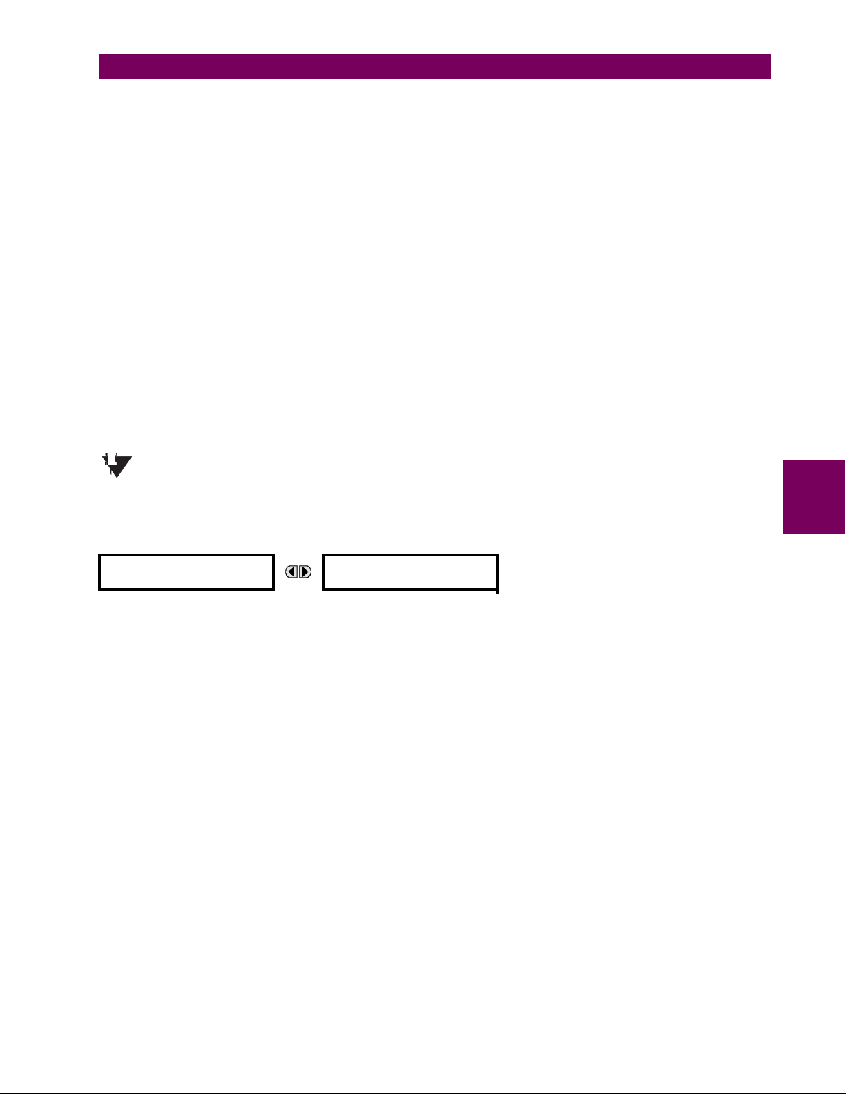
5 SETTINGS 5.2 PRODUCT SETUP
domain contains a large number of UR-series specific data items that are not available in the IEC 61850 logical nodes. This
data does not follow the IEC 61850 naming conventions. For communications schemes that strictly follow the IEC 61850
standard, this setting should be “Disabled”.
The IEC 61850 logical node name prefix settings are used to create name prefixes to uniquely identify each logical node.
For example, the logical node “MMXU1” may have the name prefix “abc”. The full logical node name will then be
“abcMMXU1”. This conforms to the IEC 61850 standard.
The MMXU deadband settings represent the deadband values used to determine when the update the MMXU “mag” and
“cVal” values from the associated “instmag” and “instcVal” values. The “mag” and “cVal” values are used for the IEC 61850
buffered and unbuffered reports. These settings correspond to the associated “db” data items in the CF functional constraint of the MMXU logical node, as per the IEC 61850 standard. According to IEC 61850-7-3, the db value “shall represent the percentage of difference between the max and min in units of 0.00%”. Thus, it is important to know the maximum
value for each MMXU measured quantity, since this represents the 100.00% value for the deadband. The minimum value
for all quantities is 0; the maximum values are as follows:
phase current: 46 × phase CT primary setting
neutral current: 46 × ground CT primary setting
voltage: 275 × VT ratio setting
power (real, reactive, and apparent): 46 × phase CT primary setting × 275 × VT ratio setting
frequency: 90 Hz
power factor: 2
The GGIO2 control configuration settings are used to set the control model for each input. The available choices are “2”
(direct control) and “3” (SBO with normal security). The GGIO2 control points are used to control the T35 virtual inputs.
Since GSSE/GOOSE messages are multicast ethernet by specification, they will not usually be forwarded by network routers. However, GOOSE messages may be fowarded by routers if the router has been configured for VLAN
NOTE
functionality.
g) WEB SERVER HTTP PROTOCOL
PATH: SETTINGS ! PRODUCT SETUP !" COMMUNICATIONS !" WEB SERVER HTTP PROTOCOL
# WEB SERVER
# HTTP PROTOCOL
HTTP TCP PORT
NUMBER: 80
Range: 1 to 65535 in steps of 1
5
The T35 contains an embedded web server and is capable of transferring web pages to a web browser such as Microsoft
Internet Explorer or Netscape Navigator. This feature is available only if the T35 has the ethernet option installed. The web
pages are organized as a series of menus that can be accessed starting at the T35 “Main Menu”. Web pages are available
showing DNP and IEC 60870-5-104 points lists, Modbus registers, Event Records, Fault Reports, etc. The web pages can
be accessed by connecting the UR and a computer to an ethernet network. The Main Menu will be displayed in the web
browser on the computer simply by entering the IP address of the T35 into the “Address” box on the web browser.
GE Multilin T35 Transformer Management Relay 5-17
Page 96

5.2 PRODUCT SETUP 5 SETTINGS
h) TFTP PROTOCOL
PATH: SETTINGS ! PRODUCT SETUP !" COMMUNICATIONS !" TFTP PROTOCOL
# TFTP PROTOCOL
#
MESSAGE
MESSAGE
TFTP MAIN UDP PORT
NUMBER: 69
TFTP DATA UDP PORT 1
NUMBER: 0
TFTP DATA UDP PORT 2
NUMBER: 0
Range: 1 to 65535 in steps of 1
Range: 0 to 65535 in steps of 1
Range: 0 to 65535 in steps of 1
The Trivial File Transfer Protocol (TFTP) can be used to transfer files from the T35 over a network. The T35 operates as a
TFTP server. TFTP client software is available from various sources, including Microsoft Windows NT. The dir.txt file
obtained from the T35 contains a list and description of all available files (event records, oscillography, etc.).
i) IEC 60870-5-104 PROTOCOL
PATH: SETTINGS ! PRODUCT SETUP !" COMMUNICATIONS !" IEC 60870-5-104 PROTOCOL
# IEC 60870-5-104
# PROTOCOL
MESSAGE
IEC 60870-5-104
FUNCTION: Disabled
IEC TCP PORT
NUMBER: 2404
Range: Enabled, Disabled
Range: 1 to 65535 in steps of 1
# IEC NETWORK
# CLIENT ADDRESSES
IEC COMMON ADDRESS
OF ASDU: 0
IEC CYCLIC DATA
PERIOD: 60 s
NUMBER OF SOURCES
IN MMENC1 LIST: 1
IEC CURRENT DEFAULT
THRESHOLD: 30000
IEC VOLTAGE DEFAULT
THRESHOLD: 30000
IEC POWER DEFAULT
THRESHOLD: 30000
IEC ENERGY DEFAULT
THRESHOLD: 30000
IEC OTHER DEFAULT
THRESHOLD: 30000
Range: 0 to 65535 in steps of 1
Range: 1 to 65535 s in steps of 1
Range: 1 to 6 in steps of 1
Range: 0 to 65535 in steps of 1
Range: 0 to 65535 in steps of 1
Range: 0 to 65535 in steps of 1
Range: 0 to 65535 in steps of 1
Range: 0 to 65535 in steps of 1
5
MESSAGE
MESSAGE
MESSAGE
MESSAGE
MESSAGE
MESSAGE
MESSAGE
MESSAGE
MESSAGE
The T35 supports the IEC 60870-5-104 protocol. The T35 can be used as an IEC 60870-5-104 slave device connected to a
maximum of two masters (usually either an RTU or a SCADA master station). Since the T35 maintains two sets of IEC
60870-5-104 data change buffers, no more than two masters should actively communicate with the T35 at one time.
NUMBER OF SOURCES IN MMENC1 LIST setting allows the selection of the number of current/voltage source values that
The
are included in the M_ME_NC_1 (measured value, short floating point) Analog points list. This allows the list to be customized to contain data for only the sources that are configured.
The IEC ------- DEFAULT THRESHOLD settings are the values used by the T35 to determine when to trigger spontaneous
responses containing M_ME_NC_1 analog data. These settings group the T35 analog data into types: current, voltage,
power, energy, and other. Each setting represents the default threshold value for all M_ME_NC_1 analog points of that
type. For example, in order to trigger spontaneous responses from the T35 when any current values change by 15 A, the
IEC CURRENT DEFAULT THRESHOLD setting should be set to 15. Note that these settings are the default values of the dead-
5-18 T35 Transformer Management Relay GE Multilin
Page 97
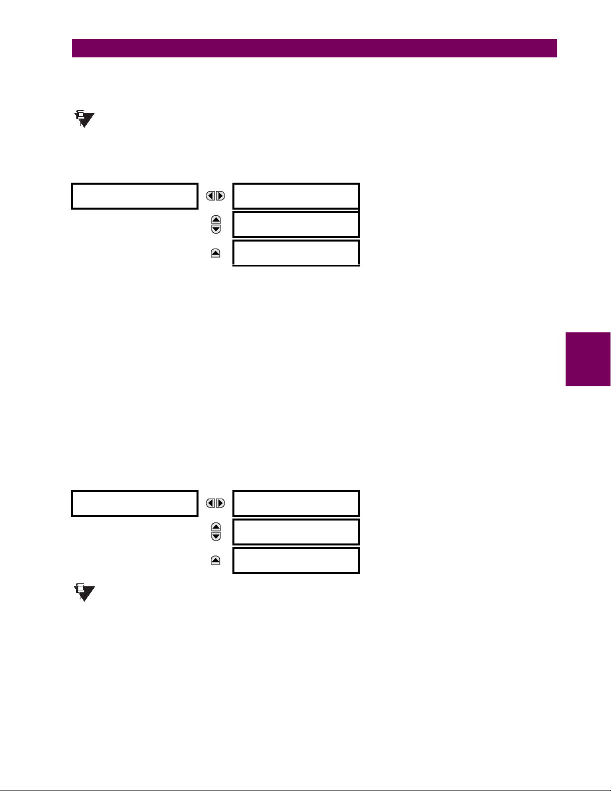
5 SETTINGS 5.2 PRODUCT SETUP
bands. P_ME_NC_1 (parameter of measured value, short floating point value) points can be used to change threshold values, from the default, for each individual M_ME_NC_1 analog point. Whenever power is removed and re-applied to the
T35, the default thresholds will be in effect.
The IEC 60870-5-104 and DNP protocols can not be used at the same time. When the IEC 60870-5-104 FUNC-
TION setting is set to “Enabled”, the DNP protocol will not be operational. When this setting is changed it
NOTE
will not become active until power to the relay has been cycled (Off/On).
j) SNTP PROTOCOL
PATH: SETTINGS ! PRODUCT SETUP !" COMMUNICATIONS !" SNTP PROTOCOL
# SNTP PROTOCOL
#
MESSAGE
MESSAGE
SNTP FUNCTION:
Disabled
SNTP SERVER IP ADDR:
0.0.0.0
SNTP UDP PORT
NUMBER: 123
Range: Enabled, Disabled
Range: Standard IP address format
Range: 0 to 65535 in steps of 1
The T35 supports the Simple Network Time Protocol specified in RFC-2030. With SNTP, the T35 can obtain clock time over
an Ethernet network. The T35 acts as an SNTP client to receive time values from an SNTP/NTP server, usually a dedicated
product using a GPS receiver to provide an accurate time. Both unicast and broadcast SNTP are supported.
If SNTP functionality is enabled at the same time as IRIG-B, the IRIG-B signal provides the time value to the T35 clock for
as long as a valid signal is present. If the IRIG-B signal is removed, the time obtained from the SNTP server is used. If
either SNTP or IRIG-B is enabled, the T35 clock value cannot be changed using the front panel keypad.
To use SNTP in unicast mode, SNTP SERVER IP ADDR must be set to the SNTP/NTP server IP address. Once this address is
set and
SNTP FUNCTION is “Enabled”, the T35 attempts to obtain time values from the SNTP/NTP server. Since many time
values are obtained and averaged, it generally takes three to four minutes until the T35 clock is closely synchronized with
the SNTP/NTP server. It may take up to one minute for the T35 to signal an SNTP self-test error if the server is offline.
To use SNTP in broadcast mode, set the SNTP SERVER IP ADDR setting to “0.0.0.0” and SNTP FUNCTION to “Enabled”. The
T35 then listens to SNTP messages sent to the “all ones” broadcast address for the subnet. The T35 waits up to eighteen
minutes (>1024 seconds) without receiving an SNTP broadcast message before signaling an SNTP self-test error.
The UR-series relays do not support the multicast or anycast SNTP functionality.
5
k) EGD PROTOCOL
PATH: SETTINGS ! PRODUCT SETUP !" COMMUNICATIONS !" EGD PROTOCOL
# EGD PROTOCOL
#
MESSAGE
MESSAGE
# FAST PROD EXCH 1
# CONFIGURATION
# SLOW PROD EXCH 1
# CONFIGURATION
# SLOW PROD EXCH 2
# CONFIGURATION
The Ethernet Global Data (EGD) protocol settings are only available if CPU Type 9G or 9H is ordered.
NOTE
The relay supports one fast Ethernet Global Data (EGD) exchange and two slow EGD exchanges. There are 20 data items
in the fast-produced EGD exchange and 50 data items in each slow-produced exchange.
Ethernet Global Data (EGD) is a suite of protocols used for the real-time transfer of data for display and control purposes.
The relay can be configured to ‘produce’ EGD data exchanges, and other devices can be configured to ‘consume’ EGD
data exchanges. The number of produced exchanges (up to three), the data items in each exchange (up to 50), and the
exchange production rate can be configured.
GE Multilin T35 Transformer Management Relay 5-19
Page 98

5.2 PRODUCT SETUP 5 SETTINGS
EGD cannot be used to transfer data between UR-series relays. The relay supports EGD production only. An EGD
exchange will not be transmitted unless the destination address is non-zero, and at least the first data item address is set to
a valid Modbus register address. Note that the default setting value of “0” is considered invalid.
The settings menu for the fast EGD exchange is shown below:
PATH: SETTINGS ! PRODUCT SETUP !" COMMUNICATIONS !" EGD PROTOCOL ! FAST PROD EXCH 1 CONFIGURATION
# FAST PROD EXCH 1
# CONFIGURATION
MESSAGE
MESSAGE
MESSAGE
MESSAGE
EXCH 1 FUNCTION:
Disable
EXCH 1 DESTINATION:
0.0.0.0
EXCH 1 DATA RATE:
1000 ms
EXCH 1 DATA ITEM 1:
0
↓
EXCH 1 DATA ITEM 20:
0
Range: Disable, Enable
Range: standard IP address
Range: 50 to 1000 ms in steps of 1
Range: 0 to 65535 in steps of 1
(Modbus register address range)
Range: 0 to 65535 in steps of 1
(Modbus register address range)
Fast exchanges (50 to 1000 ms) are generally used in control schemes. The T35 has one fast exchange (Exchange 1) and
two slow exchanges (Exchanges 2 and 3).
The settings menu for the slow EGD exchanges is shown below:
PATH: SETTINGS ! PRODUCT SETUP !" COMMUNICATIONS !" EGD PROTOCOL ! SLOW PROD EXCH 1(2) CONFIGURATION
5
# SLOW PROD EXCH 1
# CONFIGURATION
MESSAGE
MESSAGE
MESSAGE
MESSAGE
EXCH 1 FUNCTION:
Disable
EXCH 1 DESTINATION:
0.0.0.0
EXCH 1 DATA RATE:
1000 ms
EXCH 1 DATA ITEM 1:
0
↓
EXCH 1 DATA ITEM 50:
0
Range: Disable, Enable
Range: standard IP address
Range: 500 to 1000 ms in steps of 1
Range: 0 to 65535 in steps of 1
(Modbus register address range in decimal)
Range: 0 to 65535 in steps of 1
(Modbus register address range in decimal)
Slow EGD exchanges (500 to 1000 ms) are generally used for the transfer and display of data items. The settings for the
fast and slow exchanges are described below:
• EXCH 1 DESTINATION: This setting specifies the destination IP address of the produced EGD exchange. This is usu-
ally unicast or broadcast.
• EXCH 1 DATA RATE: This setting specifies the rate at which this EGD exchange is transmitted. If the setting is 50 ms,
the exchange data will be updated and sent once every 50 ms. If the setting is 1000 ms, the exchange data will be
updated and sent once per second. EGD exchange 1 has a setting range of 50 to 1000 ms. Exchanges 2 and 3 have a
setting range of 500 to 1000 ms.
• EXCH 1 DATA ITEM 1 to 20/50: These settings specify the data items that are part of this EGD exchange. Almost any
data from the T35 memory map can be configured to be included in an EGD exchange. The settings are the starting
Modbus register address for the data item in decimal format. Refer to Appendix B for the complete Modbus memory
map. Note that the Modbus memory map displays shows addresses in hexadecimal format; as such, it will be necessary to convert these values to decimal format before entering them as values for these setpoints.
5-20 T35 Transformer Management Relay GE Multilin
Page 99

5 SETTINGS 5.2 PRODUCT SETUP
To select a data item to be part of an exchange, it is only necessary to choose the starting Modbus address of the item.
That is, for items occupying more than one Modbus register (e.g. 32 bit integers and floating point values), only the first
Modbus address is required. The EGD exchange configured with these settings contains the data items up to the first
setting that contains a Modbus address with no data, or 0. That is, if the first three settings contain valid Modbus
addresses and the fourth is 0, the produced EGD exchange will contain three data items.
5.2.5 MODBUS USER MAP
PATH: SETTINGS ! PRODUCT SETUP !" MODBUS USER MAP
# MODBUS USER MAP #
MESSAGE
ADDRESS 1: 0
VALUE: 0
↓
ADDRESS 256: 0
VALUE: 0
Range: 0 to 65535 in steps of 1
Range: 0 to 65535 in steps of 1
The Modbus User Map provides read-only access for up to 256 registers. To obtain a memory map value, enter the desired
address in the
played in the
ADDRESS lines incremented by “1”. An address value of “0” in the initial register means “none” and values of “0” will be dis-
played for all registers. Different
ADDRESS line (this value must be converted from hex to decimal format). The corresponding value is dis-
VAL UE line. A value of “0” in subsequent register ADDRESS lines automatically returns values for the previous
ADDRESS values can be entered as required in any of the register positions.
These settings can also be used with the DNP protocol. See the DNP Analog Input Points section in Appendix E for details.
NOTE
5.2.6 REAL TIME CLOCK
5
PATH: SETTINGS ! PRODUCT SETUP !" REAL TIME CLOCK
# REAL TIME
# CLOCK
MESSAGE
IRIG-B SIGNAL TYPE:
None
REAL TIME CLOCK
EVENTS: Disabled
Range: None, DC Shift, Amplitude Modulated
Range: Disabled, Enabled
The date and time for the relay clock can be synchronized to other relays using an IRIG-B signal. It has the same accuracy
as an electronic watch, approximately ±1 minute per month. An IRIG-B signal may be connected to the relay to synchronize
the clock to a known time base and to other relays. If an IRIG-B signal is used, only the current year needs to be entered.
See also the
The
REAL TIME CLOCK EVENTS setting allows changes to the date and/or time to be captured in the event record.
COMMANDS !" SET DATE AND TIME menu for manually setting the relay clock.
GE Multilin T35 Transformer Management Relay 5-21
Page 100
5.2 PRODUCT SETUP 5 SETTINGS
5.2.7 USER-PROGRAMMABLE FAULT REPORT
PATH: SETTINGS ! PRODUCT SETUP !" USER-PROGRAMMABLE FAULT REPORT ! USER-PROGRAMMABLE FAULT REPORT 1(2)
# USER-PROGRAMMABLE
# FAULT REPORT 1
MESSAGE
MESSAGE
MESSAGE
MESSAGE
MESSAGE
FAULT REPORT 1
FUNCTION: Disabled
PRE-FAULT 1 TRIGGER:
Off
FAULT 1 TRIGGER:
Off
FAULT REPORT 1 #1:
Off
FAULT REPORT 1 #2:
Off
↓
FAULT REPORT 1 #32:
Off
Range: Disabled, Enabled
Range: FlexLogic™ operand
Range: FlexLogic™ operand
Range: Off, any actual value analog parameter
Range: Off, any actual value analog parameter
Range: Off, any actual value analog parameter
When enabled, this function monitors the pre-fault trigger. The pre-fault data are stored in the memory for prospective creation of the fault report on the rising edge of the pre-fault trigger. The element waits for the fault trigger as long as the prefault trigger is asserted, but not shorter than 1 second. When the fault trigger occurs, the fault data is stored and the complete report is created. If the fault trigger does not occur within 1 second after the pre-fault trigger drops out, the element
resets and no record is created.
5
The user programmable record contains the following information: the user-programmed relay name, detailed firmware
revision (4.6x, for example) and relay model (T35), the date and time of trigger, the name of pre-fault trigger (specific FlexLogic™ operand), the name of fault trigger (specific FlexLogic™ operand), the active setting group at pre-fault trigger, the
active setting group at fault trigger, pre-fault values of all programmed analog channels (one cycle before pre-fault trigger),
and fault values of all programmed analog channels (at the fault trigger).
The report includes fault duration times for each of the breakers (created by the Breaker Arcing Current feature). To include
fault duration times in the fault report, the user must enable and configure Breaker Arcing Current feature for each of the
breakers. Fault duration is reported on a per-phase basis.
Each fault report is stored as a file to a maximum capacity of ten files. An eleventh trigger overwrites the oldest file. The
EnerVista UR Setup software is required to view all captured data. A
FAULT RPT TRIG event is automatically created when
the report is triggered.
The relay includes two user-programmable fault reports to enable capture of two types of trips (for example, trip from thermal protection with the report configured to include temperatures, and short-circuit trip with the report configured to include
voltages and currents). Both reports feed the same report file queue.
The last record is available as individual data items via communications protocols.
• PRE-FAULT 1 TRIGGER: Specifies the FlexLogic™ operand to capture the pre-fault data. The rising edge of this
operand stores one cycle-old data for subsequent reporting. The element waits for the fault trigger to actually create a
record as long as the operand selected as
PRE-FAULT TRIGGER is “On”. If the operand remains “Off” for 1 second, the
element resets and no record is created.
• FAULT 1 TRIGGER: Specifies the FlexLogic™ operand to capture the fault data. The rising edge of this operand
stores the data as fault data and results in a new report. The trigger (not the pre-fault trigger) controls the date and time
of the report.
• FAULT REPORT 1 #1 to #32: These settings specify an actual value such as voltage or current magnitude, true RMS,
phase angle, frequency, temperature, etc., to be stored should the report be created. Up to 32 channels can be configured. Two reports are configurable to cope with variety of trip conditions and items of interest.
5-22 T35 Transformer Management Relay GE Multilin
 Loading...