

Page 1

GE Healthcare
T2100-ST1 Treadmill, 110V / T2100-ST2 Treadmill,
All Rights Reserved
T2100-ST1
Treadmill, 110V
T2100-ST2
Treadmill, 220V
Service Manual
2097937-002 Rev G
220V
English
© 2016-2019 General Electric Company
Page 2

Publication Information
The information in this manual applies only to the T2100-ST1 (GE PN 2097357-001) and T2100-ST2 (GE PN
2097357-002) treadmills. It does not apply to earlier versions. Due to continuing product innovation,
specifications in this manual are subject to change without notice.
T2100-ST1, T2100-ST2, CASE, CardioSoft, and MAC are trademarks owned by GE Medical Systems
Information Technologies, Inc., a General Electric Company going to market as GE Healthcare. All other
marks are the properties of their respective owners.
This product complies with the regulatory requirements concerning medical devices from the following
bodies:
The T2100-ST1 and T2100-ST2 treadmills meet the following safety and regulatory standards for FDA
Class 1 motor operated physical medicine machines. They have been tested by Intertek Testing Services
N.A Inc., and are listed by Engineering Testing Laboratories (ETL). However, the ultimate conformance to
IEC 6060-1 2005-3rd edition is the responsibility of the system integrator when combined with other
equipment. Additionally, all motorized equipment is potentially dangerous if used incorrectly. Before
using the T2100-ST1 or T2100-ST2 treadmill, follow all precautions listed in this manual and read the
entire operator’s manual thoroughly. Use the T2100-ST1 and T2100-ST2 treadmills only as described.
Revision History
The document part number and revision appear at the bottom of each page. The revision identifies the
document’s update level. The revision history of this document is summarized in the following table.
Revision Publication Date Description
A
B
C
D
E
F
G
To access other GE Healthcare manuals, go to the Common Documentation Library (CDL), located at
http://apps.gehealthcare.com/servlet/ClientServlet?REQ=RNEW&MODALITY=Cardiology.
20 August 2016
9 September 2016
18 November 2016
4 April 2017
12 June 2017
27 June 2018
22 January 2019
Internal release
Initial public release
Power cord configuration
Updated eStop button
Added power cord configuration
Revised regulatory & safety conformance
Added EMC Declaration and 4
th
Edition Configuration
2 T2100-ST1 Treadmill, 110V / T2100-ST2 Treadmill, 220V 2097937-002 Rev G
11 March 2019
Page 3

Contents
1 Introduction ............................................................................................................ 9
Intended User ......................................................................................................... 9
Indications for Use ................................................................................................ 9
Prescription Device Statement ........................................................................... 9
Regulatory and Safety Information ................................................................... 9
Safety Conventions ................................................................................... 10
Safety Hazards........................................................................................... 10
Classification of Medical Device ............................................................. 13
Regulatory and Safety Conformance .................................................... 13
Table 1: Guidance and Manufacturer’s Declaration - Emissions ..... 14
Table 2: Guidance and Manufacturer’s Declaration – Immunity All
ME Equipment and ME Systems ............................................................. 15
Table 3: Guidance and Manufacturer’s Declaration – Immunity ME
Equipment and ME Systems that is NOT Life-supporting ................. 16
Table 4: Recommended Separation Distances between portable and
mobile RF Communications equipment and the T2100-ST Series ME
Equipment and ME Systems that is NOT Life-supporting ................. 17
Responsibility of the Manufacturer ....................................................... 17
Responsibility of the Customer .............................................................. 18
Product and Package Information ......................................................... 20
Symbols ....................................................................................................... 20
Equipment Identification ................................................................................... 23
Product Label ............................................................................................. 23
Service Information ............................................................................................ 24
Service Requirements ............................................................................... 24
Warranty Information .............................................................................. 24
Additional Assistance ............................................................................... 24
Manual Information ............................................................................................ 25
Manual Purpose ......................................................................................... 25
Document Conventions............................................................................ 25
Related Documents .................................................................................. 26
2 Product Overview ................................................................................................ 29
Safety Systems .................................................................................................... 30
Treadmill ............................................................................................................... 30
Drive System ........................................................................................................ 30
Speed Range ......................................................................................................... 30
Incline Range ........................................................................................................ 30
Running Surface .................................................................................................. 30
Communication Ports ......................................................................................... 31
2097937-002 Rev G T2100-ST1 Treadmill, 110V / T2100-ST2 Treadmill, 220V 3
11 March 2019
Page 4

Floor Surface Footprint ...................................................................................... 31
Operating and Storage Condition Recommendations ................................. 31
Power Requirements .......................................................................................... 31
3 Assembly and Setup ............................................................................................ 35
Safe Handling Guidelines ................................................................................... 35
Initial Setup .......................................................................................................... 36
Location ................................................................................................................ 37
Electrical Safety Tests ........................................................................................ 38
AC Line Voltage Test ................................................................................. 38
Power Cord and Plug ................................................................................ 39
Ground Continuity Test ............................................................................ 39
Conducting Leakage Tests ...................................................................... 40
Leakage Test Diagrams ........................................................................... 41
Secure Cables ....................................................................................................... 42
Running Belt Tracking Adjustment .................................................................. 42
Running Belt Tension Adjustment .................................................................... 42
Drive Belt Tension Adjustment ......................................................................... 43
Test Plug Procedure ............................................................................................ 43
Communication Ports ......................................................................................... 43
Using the test plug .............................................................................................. 44
Setup and Connection to Host .......................................................................... 45
CASE connection and setup: .................................................................... 45
CardioSoft/CS connection and setup: ................................................... 47
MAC 5500 ST connection and setup: ...................................................... 53
MAC 2000 ST connection and setup: ...................................................... 54
4 Preventive Maintenance ..................................................................................... 57
Daily Maintenance .............................................................................................. 57
Weekly Maintenance .......................................................................................... 58
Monthly Maintenance ........................................................................................ 58
Semiannual Maintenance .................................................................................. 58
Belt Cleaning and Inspection ............................................................................ 58
Running Belt Tracking Adjustment .................................................................. 59
Running Belt Tension Adjustment .................................................................... 60
Drive Belt Tension Adjustment ......................................................................... 60
Exterior Care ........................................................................................................ 62
Elevation Screw Lubrication.............................................................................. 62
Running Deck Maintenance .............................................................................. 63
4 T2100-ST1 Treadmill, 110V / T2100-ST2 Treadmill, 220V 2097937-002 Rev G
11 March 2019
Page 5

5 Theory of Operation ............................................................................................ 65
Scope ..................................................................................................................... 65
T2100-ST Series Block Diagram ........................................................................ 66
Smart Power Supply (PCB) Overview ............................................................... 67
Software Requirements ..................................................................................... 68
Speed Control ............................................................................................. 68
Elevation Control ....................................................................................... 68
ESTOP ..................................................................................................................... 69
Communication Hardware (RS-232 Configuration) ...................................... 69
Communication Hardware (USB Configuration)............................................ 70
Self-Test Mode ..................................................................................................... 70
Calibration ............................................................................................................ 71
DIP Switch Settings ............................................................................................. 71
Electrical Inputs ................................................................................................... 71
Electrical Outputs ................................................................................................ 72
Electrical Connections ........................................................................................ 72
Physical Requirements and Restrictions ........................................................ 73
6 Troubleshooting ................................................................................................... 75
Troubleshooting Guidance Base on Error Code ............................................ 76
Incoming Power 110-240VAC Flow Chart 1A ................................................. 78
Incoming Power Inline Filter Flow Chart 1B ................................................... 79
Incoming Power Drive PC2303-012-N Flow Chart 1C ................................... 80
Smart Power Supply Incoming Power 110-240VAC Flow Chart 1D ........... 81
Emergency Stop Flow Chart 1E ........................................................................ 82
Pull Tether Flow Chart 1F ................................................................................... 83
Communication RS232 Flow Chart 1G ............................................................ 84
Communication USB Flow Chart 1H ................................................................ 85
Smart Power Supply Error Code Identification Flow Chart 1I .................... 86
Smart Power Supply Error Code 1 Flow Chart 1J “Bad Calibration Error
(1)” 87
Smart Power Supply FGLF0495-1 Error Code 2 Flow Chart 1K “Elevation
Error (2)” ................................................................................................................ 88
Smart Power Supply FGLF0495-03 Error Code 2 Flow Chart 1KK “Elevation
Error (2)” ................................................................................................................ 89
Smart Power Supply Error Code 3 Flow Chart 1L “Zero Speed Motor
Controller Error (3)” ............................................................................................. 90
2097937-002 Rev G T2100-ST1 Treadmill, 110V / T2100-ST2 Treadmill, 220V 5
11 March 2019
Page 6

Smart Power Supply Error Code 4 Flow Chart 1M “Over Speed Motor
Controller Error (4)” ............................................................................................. 91
Smart Power Supply Error Code 5 Flow Chart 1N “Over Speed External
Sensor Error (5)” ................................................................................................... 92
Smart Power Supply Error Code 7 Flow Chart 1P “Speed Compare Error
(7)” 94
Smart Power Supply Error Code 8 Flow Chart 1L “Motor Controller Fault
Signal (8)” .............................................................................................................. 96
Smart Power Supply Error Code 9 Flow Chart 1R “Belt Start Reject Error
(9)” 97
Drive PC2303-012-N status LED CODE list ..................................................... 98
Running Belt High Speed Application .............................................................. 98
System Flash Log Retrieval ............................................................................... 98
7 Field Replaceable Units ..................................................................................... 100
Final Assembly ................................................................................................... 100
Final Assembly Circuit Board Connection .................................................... 101
Deck Assembly ................................................................................................... 104
Frame Assembly ................................................................................................ 106
Motor Pan Assembly ......................................................................................... 108
Motor Pan Assembly Wiring ............................................................................ 111
Motor Mount Assembly .................................................................................... 115
Circuit Board Assembly FGLF0495-1 ............................................................. 116
Circuit Board Assembly FGLF0495-3 ............................................................. 117
Pull Tether Assembly ........................................................................................ 119
Emergency Stop Assembly .............................................................................. 120
Communication Cables .................................................................................... 120
Calibration Software ......................................................................................... 121
8 Component/FRU Removal and Replacement ............................................... 123
Established Component Replacement Times .............................................. 123
Comprehensive Tool List .................................................................................. 124
Replacing the Hood ........................................................................................... 125
Replacing the Drive Motor ............................................................................... 126
Replacing the Drive ........................................................................................... 129
Replacing the Front Roller ............................................................................... 131
Replacing the Rear Roller ................................................................................ 132
Replacing the Running Belt ............................................................................. 134
6 T2100-ST1 Treadmill, 110V / T2100-ST2 Treadmill, 220V 2097937-002 Rev G
11 March 2019
Page 7

Replacing the Running Deck ........................................................................... 137
Replacing the Deck Cushion ............................................................................ 138
Replacing the Motor Drive Belt ....................................................................... 140
Replacing/Adjusting the Elevation Actuator ............................................... 142
Replacing the Smart Power Supply Relay Board ........................................ 143
Replacing the Circuit Breaker ......................................................................... 145
Relocating the ESB and STS Assembly .......................................................... 146
Replacing the Emergency Stop Button (ESB) ............................................... 148
Replacing the Stop Tether Switch (STS) ......................................................... 150
Replacing the Right or Left Handrail ............................................................. 151
Replacing the Center Handrail ....................................................................... 153
Removing and Reinstalling the Handrails for Moving ................................ 154
Replacing the Main power switch .................................................................. 155
Adjusting the Run Belt Tracking and Tension .............................................. 156
Adjusting belt tracking ........................................................................... 156
Adjusting belt tension ............................................................................ 157
Replacing the Power cord ................................................................................ 157
Replacing the CE filter ...................................................................................... 158
Replacing the Relay .......................................................................................... 159
9 Calibration ........................................................................................................... 161
Installing the T2100-ST Series Calibration Software .................................. 161
Installing the Serial Drivers ............................................................................. 163
Software Interface Instruction T2100-ST Series Calibration .................... 167
Calibrating Speed .............................................................................................. 168
Calibrating Elevation ........................................................................................ 171
Elevation Chart ........................................................................................ 174
Elevation Actuator .................................................................................. 174
Calibration Software Tabs ............................................................................... 175
Basic Control Tab .................................................................................... 175
Advanced Control Tab ............................................................................ 176
Speed Cal Tab ........................................................................................... 177
Grade Cal Tab........................................................................................... 178
Error Code Tab ......................................................................................... 179
System Log Tab ....................................................................................... 179
10 Functional / Post Repair / Preventative Maintenance Checkout
Procedures .......................................................................................................... 181
Tools Required ................................................................................................... 181
Checkout Procedures ....................................................................................... 181
2097937-002 Rev G T2100-ST1 Treadmill, 110V / T2100-ST2 Treadmill, 220V 7
11 March 2019
Page 8

Visual/Functional Checks ...................................................................... 182
Operational Checks ................................................................................ 182
Speed Calibration .................................................................................... 182
Elevation Calibration .............................................................................. 183
Test Plug Check ........................................................................................ 183
Walking Belt Tension / Tracking ........................................................... 183
Walking Belt Speed Verification ........................................................... 183
Host Communication .............................................................................. 184
Electrical Safety Checks ......................................................................... 184
Preventative Maintenance Visual/Functional Checks ..................... 185
Procedural Lists ................................................................................................. 185
FRU Repairs / Exchange ......................................................................... 186
Final Checkout Preventative Maintenance Test ................................ 188
A Maintenance Log ............................................................................................... 189
B Reference Documents ....................................................................................... 191
8 T2100-ST1 Treadmill, 110V / T2100-ST2 Treadmill, 220V 2097937-002 Rev G
11 March 2019
Page 9

1
1 Introduction
This document describes the T2100-ST1 and T2100-ST2
treadmills also referred to as the “system”, “device”, or
“product”. The document is intended to be used by service
personnel.
This chapter provides general information required for the
proper use of the system and this manual. Familiarize yourself
with this information before using the system.
Intended User
This manual is intended for service personnel responsible for the
maintenance and repair of the T2100-ST1 and T2100-ST2
treadmills.
Indications for Use
The T2100-ST1 and T2100-ST2 treadmills are designed for
cardiac stress testing.
Prescription Device Statement
CAUTION:
United States federal law restricts this device to sale by, or
on the order of, a physician.
Regulatory and Safety Information
This section provides information about the safe use and
2097937-002 Rev G T2100-ST1 Treadmill, 110V / T2100-ST2 Treadmill, 220V 9
11 March 2019
regulatory compliance of this system. Familiarize yourself with
this information, read and understand all instructions before
attempting to use this system. The system was designed and
manufactured to the appropriate medical regulations and
controls.
Page 10

Introduction
NOTE:
Disregarding the safety information provided in this
manual is considered abnormal use of this system and
could result in injury, loss of data, and void any existing
product warranties.
Safety Conventions
A Hazard is a source of potential injury to a person, property, or
the system.
This manual uses the terms DANGER, WARNING, CAUTION, and
NOTICE to point out hazards and to designate a degree or level
of seriousness. Familiarize yourself with the following definitions
and their significance.
Definition of Safety Conventions
Convention Definition
DANGER Indicates an imminent hazard, which, if not avoided, will
result in death or serious injury.
WARNING Indicates a potential hazard or unsafe practice, which, if not
avoided, could result in death or serious injury.
CAUTION Indicates a potential hazard or unsafe practice, which, if not
avoided, could result in moderate or minor injury.
NOTICE Indicates a potential hazard or unsafe practice, which, if not
avoided, could result in loss or destruction of property or
data.
Safety Hazards
The following messages apply to the system as a whole. Specific
messages may also appear elsewhere in the manual.
WARNING:
The T2100-ST1 and T2100-ST2 treadmills are manufactured
to exacting standards both in physical form and in
component selection. The components used in our products
have been selected with performance and medical safety in
mind. The treadmills have been engineered and certified to
conform to the list of medical and safety regulatory
standards which appear on the next page. Modification or
part substitution of any kind is strictly forbidden. Any
deviation in component replacement, physical or electrical
modification will result in loss of medical safety certification
and warranty of this product. Modifications to this
equipment may put the patient at risk of electrical shock or
hardware malfunction.
Contact GE Healthcare Service department for all your repair
part needs.
10 T2100-ST1 Treadmill, 110V / T2100-ST2 Treadmill, 220V 2097937-002 Rev G
11 March 2019
Page 11

Introduction
WARNING:
The T2100-ST1 and T2100-ST2 treadmills must be grounded
to reduce the risk of electrical shock. If a malfunction
occurs, grounding provides a path of least resistance for an
electric current. Ungrounded connections must not be
used.
No other equipment may be used on the electrical circuit
with the treadmills. Do not use extension cords. Using a
shared or unreliable circuit can also cause the treadmills to
unexpectedly shut off, potentially resulting in injury to the
patient.
Ensure the master power switch is in the off position before
plugging in the T2100-ST1 or T2100-ST2. A power surge
could damage the sophisticated electronic system of the
treadmills.
WARNING:
Before permitting anyone to use the T2100-ST Series, do the
following:
• Warn each user about the risk of falling while the belt is in
motion.
• Stress the need for caution.
• Demonstrate the proper mounting and dismounting
methods.
• Show each user how to use the T2100-ST Series as
described in this manual.
• Ask each user to perform a supervised "test usage" at
minimum belt speed to review and practice usage
techniques.
• Observe all the precautions listed under “Customer “on
page 18 to reduce the possibility of serious injury as a
result of falling or a loss of balance.
WARNING:
Serious injury or death could result from electrical shock. To
reduce the possibility of electrical shock, carefully observe
the following precautions.
• To disconnect the treadmill, set the power switch to the
OFF position, and remove the plug from the outlet. When
the power is off, the green light on the power switch is
dark.
• Never operate the unit with a damaged power cord or
plug.
2097937-002 Rev G T2100-ST1 Treadmill, 110V / T2100-ST2 Treadmill, 220V 11
11 March 2019
Page 12

Introduction
• Power cord should be routed through frame-mounted
clamp and kept clear of the elevation mechanism.
• Communication cable should be routed through the
communication cable clamp and kept clear of the
elevation mechanism.
• Keep the power cord and communication cable out of
traffic areas and away from heated surfaces.
• Never use extension cords.
• Never operate the unit when it is wet.
• Never operate the unit if it is not operating properly.
• Always unplug the machine before service or
maintenance is performed.
• Treadmill should be serviced by authorized technicians
only.
• Operator should report any electrical shock when
touching the treadmill and discontinue use immediately.
• Never use the treadmill outdoors.
• Immediately discontinue use and unplug the treadmill if
you smell the distinctive odor of hot electrical
components.
WARNING:
Serious injury or death could result from electrical shock
occurring during defibrillation. Never allow patient or
operators near treadmill during defibrillation.
WARNING:
Consult your physician prior to using this appliance to
determine the patient’s physical readiness and capabilities.
Stop exercising immediately and seek medical attention if
the patient experience chest pain, dizziness or shortness of
breath or if you experience symptoms of overexertion.
WARNING:
Serious injury or death could result from operating the
treadmill in the presence of explosive or flammable vapors
and antiseptics.
WARNING:
The potential for foot crush injury at frontal end of
treadmill at lift mechanism (landing gear) when treadmill is
descending. Keep feet and hands away from this area at all
times.
12 T2100-ST1 Treadmill, 110V / T2100-ST2 Treadmill, 220V 2097937-002 Rev G
11 March 2019
Page 13

Introduction
Potential foot crush injury at rearward side rail, rear of side
rail and rear roller exists when treadmill approaches full
elevation. Keep feet and hands away from this area at all
times.
Classification of Medical Device
This device is classified as follows, according to IEC 60601-1:
Medical Device Classification
Category Classification
Type of protection against
electrical shock
Degree of protection against
electrical shocks
Degree of protection against
harmful ingress or water
Degree of safety of application in
the presence of a flammable
anesthetic mixture with air or with
oxygen or with nitrous oxide
Method(s) of sterilization or
disinfection recommended by the
manufacturer
Mode of operation Continuous operation.
Class I motor operated physical
medicine machine.
Type B external application applied
part.
Ordinary equipment (enclosed
equipment without protection
against ingress of water).
Equipment is not suitable for use in
the presence of a flammable
anesthetic mixture with air or with
oxygen or with nitrous oxide.
Not applicable
Regulatory and Safety Conformance
T2100-ST1 and T2100-ST2 treadmills meet FDA Class 1 motor
operated physical medicine machines. They have been tested by
Intertek Testing Services N.A Inc., and are listed by Engineering
Testing Laboratories (ETL). However, the ultimate conformance
to IEC 60601-1 is the responsibility of the system integrator
when combined with other equipment. Additionally, all
motorized equipment is potentially dangerous if used
incorrectly. Before using the T2100-ST1 or T2100-ST2 treadmill,
follow all precautions listed in this manual and read the entire
Operator’s Manual thoroughly. Use the T2100-ST1 and T2100ST2 treadmills only as described.
NOTE:
This equipment has been tested and found to comply with
the limits for a Class B digital device, pursuant to part 15
of the FCC Rules. These limits are designed to provide
reasonable protection against harmful interference when
the equipment is operated in a commercial environment.
This equipment generates, uses, and can radiate radio
frequency energy and, if not installed and used in
accordance with the instruction manual, may cause
2097937-002 Rev G T2100-ST1 Treadmill, 110V / T2100-ST2 Treadmill, 220V 13
11 March 2019
Page 14

Introduction
harmful interference to radio communications. Operation
of this equipment in a residential area is likely to cause
harmful interference in which case the user will be
required to correct the interference at owner’s expense.
Table 1: Guidance and Manufacturer’s Declaration Emissions
The T2100-ST Series is intended for use in the
electromagnetic environment specified below. The
customer or user of the T2100-ST Series should ensure
that it is used in such an environment.
Emissions Test Compliance
RF Emissions
CISPR 11
RF Emissions
CISPR 11
Harmonics
IEC 61000-3-2
Flicker
IEC 61000-3-3
Electromagnetic Environment Guidance
Group 1
Class B The T2100-ST Series is suitable for use in
Class A
Complies
The T2100-ST Series uses RF energy only
for its internal function. Therefore, its RF
emissions are very low and are not likely
to cause any interference in nearby
electronic equipment.
all establishments, including domestic,
and those directly connected to the
public low-voltage power supply
network that supplies buildings used for
domestic purposes.
14 T2100-ST1 Treadmill, 110V / T2100-ST2 Treadmill, 220V 2097937-002 Rev G
11 March 2019
Page 15

Introduction
Table 2: Guidance and Manufacturer’s Declaration – Immunity All ME Equipment and ME Systems
The T2100-ST Series is intended for use in the
electromagnetic environment specified below. The
customer or user of the T2100-ST Series should ensure
that it is used in such an environment.
Immunity
Test
ESD
IEC 61000-4-2
EFT
IEC 61000-4-4
Surge
IEC 61000-4-5
Voltage
Dips/Dropout
IEC 61000-411
IEC 60601
Test Level
±8kV Contact
±15kV Air
±2kV Mains
±1kV I/Os
±1kV
Differential
±2kV
Common
>95% Dip for
0.5 Cycle
60% Dip for
5 Cycles
30% Dip for
25 Cycles
>95% Dip for
5 Seconds
Compliance
Level
±8kV Contact
±15kV Air
±2kV Mains
±1kV I/Os
±1kV
Differential
±2kV
Common
>95% Dip for
0.5 Cycle
60% Dip for
5 Cycles
30% Dip for
25 Cycles
>95% Dip for
5 Seconds
Electromagnetic
Environment - Guidance
Floors should be wood,
concrete or ceramic tile.
If floors are synthetic, the
r/h should be at least
30%
Mains power quality
should be that of a
typical commercial or
hospital environment.
Mains power quality
should be that of a
typical commercial or
hospital environment.
Mains power quality
should be that of a
typical commercial or
hospital environment. If
the user of the T2100-ST
Series requires continued
operation during power
mains interruptions, it is
recommended that the
T2100-ST Series be
powered from an
uninterruptible power
supply or battery.
Power
Frequency
50/60Hz
Magnetic
Field
IEC 61000-4-8
2097937-002 Rev G T2100-ST1 Treadmill, 110V / T2100-ST2 Treadmill, 220V 15
11 March 2019
30 A/m 30 A/m,
50/60Hz
Power frequency
magnetic fields should be
that of a typical
commercial or hospital
environment.
Page 16

Introduction
3V, 6V at ISM
Table 3: Guidance and Manufacturer’s Declaration – Immunity ME Equipment and ME Systems that is NOT Life-supporting
The T2100-ST Series is intended for use in the
electromagnetic environment specified below. The
customer or user of the T2100-ST Series should ensure
that it is used in such an environment.
Immunity
Test
Conducted
RF
IEC 61000-46
Radiated RF
IEC 61000-4-
3
IEC 60601
Test Level
3 Vrms
150 kHz to
80 MHz
3 V/m
80 MHz to
2.7 GHz
Compliance
Level
+ (Amateur
Frequencies
3 V/m at 80 2,700MHz,
AM
Modulation
9-28V/m, 385
- 6,000MHz,
FM or Digital
Modulation
Electromagnetic
Environment - Guidance
Portable and mobile
communications
equipment should be
separated from the
T2100-ST Series by no less
than the distances
calculated/listed below:
D=(3.5/V1) (Sqrt P)
150kHz to 80MHz
D=(3.5/E1) (Sqrt P)
80 to 800 MHz
D=(7/E1 )(Sqrt P)
800 MHz to 2.5 GHz
where P is the max power
in watts and D is the
recommended separation
distance in meters.
Field strengths from fixed
transmitters, as
determined by an
electromagnetic site
survey, should be less
than the compliance
levels (V1 and E1).
Interference may occur in
the vicinity of equipment
containing a transmitter.
16 T2100-ST1 Treadmill, 110V / T2100-ST2 Treadmill, 220V 2097937-002 Rev G
11 March 2019
Page 17

Introduction
Table 4: Recommended Separation Distances between portable and mobile RF Communications equipment and the T2100-ST Series ME Equipment and ME Systems that is NOT Life-supporting
The T2100-ST Series is intended for use in the
electromagnetic environment in which radiated
disturbances are controlled. The customer or user of the
T2100-ST Series can help prevent electromagnetic
interference by maintaining a minimum distance between
portable and mobile RF Communications Equipment and
the T2100-ST Series as recommended below, according to
the maximum output power of the communications
equipment.
Max Output
Power
(Watts)
0.01 0.11667 0.11667 0.23333
0.1 0.36894 0.36894 0.73785
1 1.1667 1.1667 2.3333
10 3.6894 3.6894 7.3785
100 11.667 11.667 23.333
Separation (m)
150kHz to 80MHz
D=(3.5/V1)(Sqrt P)
Separation (m)
80 to 800MHz
D=(3.5/E1)(Sqrt P)
Separation (m)
800MHz to
2.5GHz
D=(7/E1)(Sqrt P)
Responsibility of the Manufacturer
Full-Vision, Inc., is responsible for the effects of safety, reliability,
and performance of the treadmill only if the following conditions
are met:
• Assembly operations, extensions, readjustments,
modifications, or repairs are carried out by GE Healthcare
which is authorized for service and installation.
• The electrical installation of the relevant room complies with
the requirements of the appropriate local, state, and other
government regulations.
• The equipment is used in accordance with the instructions
for use.
2097937-002 Rev G T2100-ST1 Treadmill, 110V / T2100-ST2 Treadmill, 220V 17
11 March 2019
Page 18

Introduction
Responsibility of the Customer
The customer is responsible for providing appropriate desks,
chairs, electrical wall outlets, network connections, and analog
phone lines, and for locating any of the system components
described in this manual in compliance with all local, state, and
national codes.
The customer is solely responsible for the training, instruction,
supervision and safety of all users of the T2100-ST Series
treadmill, and to use it as intended by the manufacturer. This
device is intended to be used as a motion appliance to facilitate
cardiac or VO2 medical evaluation.
• Read the operator’s manual before operating the T2100-ST
Series Treadmill.
• Assist in off-loading the patient in the event of abnormal or
unexpected operation of the treadmill.
• If the treadmill is not responding properly, stop the
treadmill, assist in removing the patient off the running belt,
unplug the treadmill power supply, and seek factory
authorized repair before attempting to restart the treadmill.
• Never allow children or pets near the machine without
qualified adult supervision.
• Note the location of stop and/or emergency stop controls
and their operation before starting a test or workout.
• This device is not intended for use by persons with reduced
physical, sensory or mental capabilities, or lack of
experience and knowledge unless they have been given
supervision or instruction concerning use of the appliance
by a person responsible for their safety.
• Verify the Patient and Operator both know how to stop the
machine in the event of malfunction or emergency.
• Patient should not wear loose fitting nylon material when
exercising on this treadmill to avoid generating electrostatic discharge.
• Never attempt to remove any article of clothing while the
running belt is moving.
• All persons on and around the treadmill must wear enclosed,
protective footwear. Shoe laces must be tight and not drape
as to cause a trip or catch hazard. Sandals, flip flops, slippers
and the like are not considered enclosed, protective
footwear.
• Walk in the center of the running belt. Contact with the side
rail and the moving belt could cause injury.
18 T2100-ST1 Treadmill, 110V / T2100-ST2 Treadmill, 220V 2097937-002 Rev G
11 March 2019
Page 19

Introduction
• The Patient must always wear the stop tether lanyard wrist
strap while operating the T2100-ST Series Treadmill.
• Place the treadmill on a hard, level and unobstructed
surface. See Chapter 3, “Assembly and Setup“.
• Check input power cord connection and location for
hazardous pinch points before use.
• Check input communications cord connection (if equipped)
for proper interface with all equipment.
• Keep all cords clear of patient to avoid trip hazards.
• Never attempt to remove the motor pan hood or do
electrical repairs yourself. Repairs should only be done by a
factory authorized repair provider.
• Always unplug the T2100-ST Series Treadmill when servicing,
inspecting or cleaning the treadmill.
• Routinely inspect the treadmill for loose parts.
• Inspect handrails and ensure they will support the patient
properly.
• Always start the running belt at its slowest speed before
starting the patient test.
• Do not step onto belt when it is moving.
• Always slow the running belt to its minimum speed before
stopping.
• Keep hands, feet, and clothing away from any moving parts.
• Verify no one is near the elevation mechanism before
operating. Never put any part of the body under any part of
a running treadmill.
• Never drop or insert objects into any opening.
• Never drape garments, hook-up leads, or other equipment
over the side rails or drop objects on the belt while the
T2100-ST Series Treadmill is running.
• Do not allow moisture or oils to accumulate on equipment,
creating a slip hazard.
2097937-002 Rev G T2100-ST1 Treadmill, 110V / T2100-ST2 Treadmill, 220V 19
11 March 2019
Page 20
Introduction
Product and Package Information
This section describes the location of the labels used on your
device and its packaging. It also describes the symbols used on
the labels.
Symbols
The following symbols may appear on the device or its
packaging. Familiarity with these symbols assists in the safe use
and disposal of the equipment. For equipment symbols not
shown, refer to the original equipment manufacturers (OEM)
manuals.
Symbols are used to convey warnings, cautions, prohibitions,
mandatory actions, or information. Any hazard symbols on your
device or packaging with markings in color indicates there is
certain danger and is a warning. Any hazard symbols on your
device or packaging that is in black and white indicates a
potential hazard and is a caution.
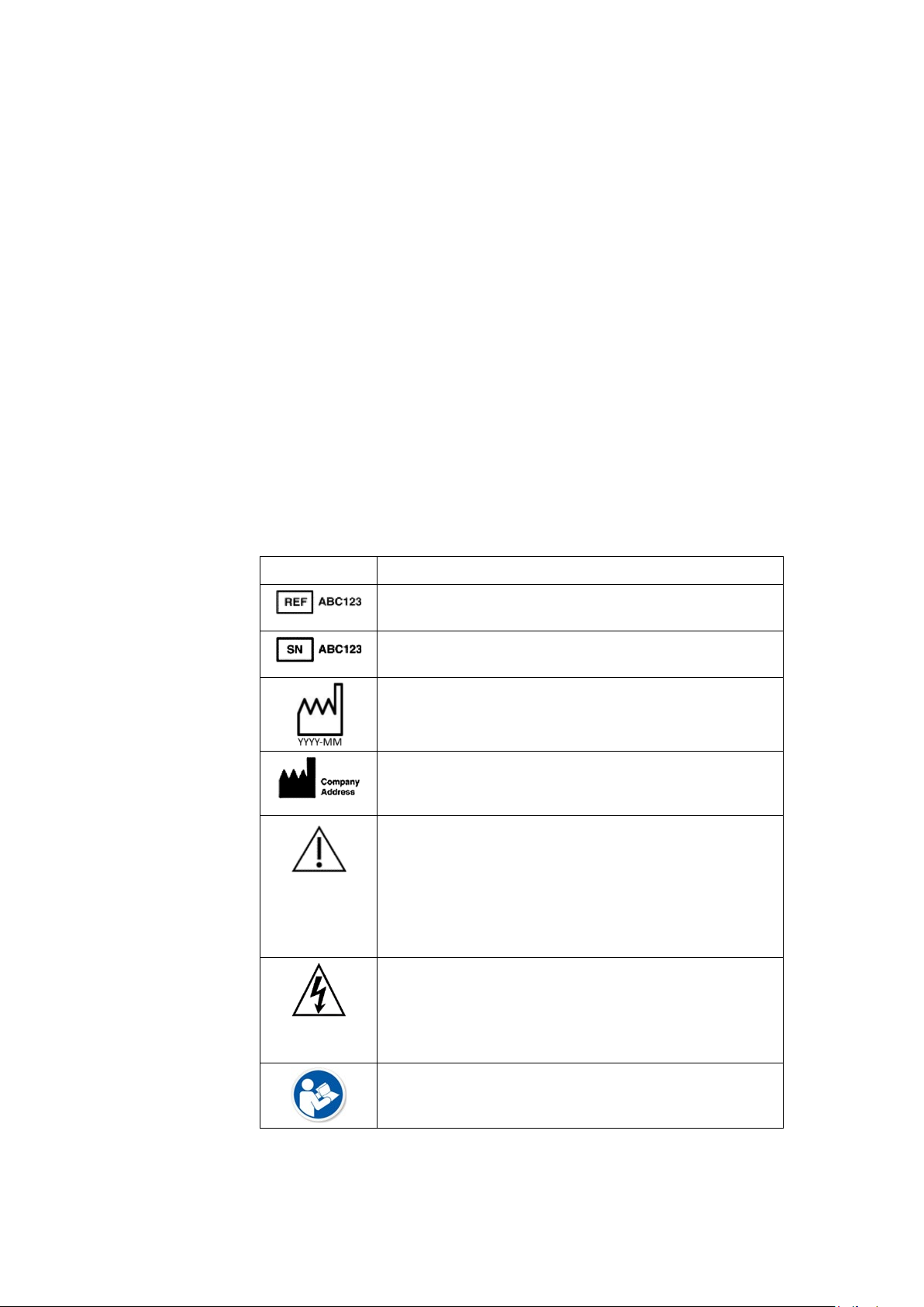
Symbols
Symbol Description
Catalog or Orderable Part Number
Indicates the manufacturer's catalog or part number.
Serial Number
Indicates the manufacturer's serial number.
Date of Manufacture (Year-Month)
Indicates the original manufacture date for this device.
Manufacturer Name and Address
Indicates the name and address for the manufacturer of
this device.
CAUTION:
CONSULT ACCOMPANYING DOCUMENTS - There
may be specific warnings or precautions associated
with the device that are not otherwise found on the
label.
Consult the accompanying documentation for more
information about safely using this device.
CAUTION:
ELECTRIC SHOCK - Indicates the presence of
hazardous energy circuits or electric shock hazards.
To reduce the risk of electric shock hazards, do not open
this enclosure. Refer servicing to qualified personnel.
Reading of the Owner’s Manual is mandatory.
20 T2100-ST1 Treadmill, 110V / T2100-ST2 Treadmill, 220V 2097937-002 Rev G
11 March 2019
Page 21
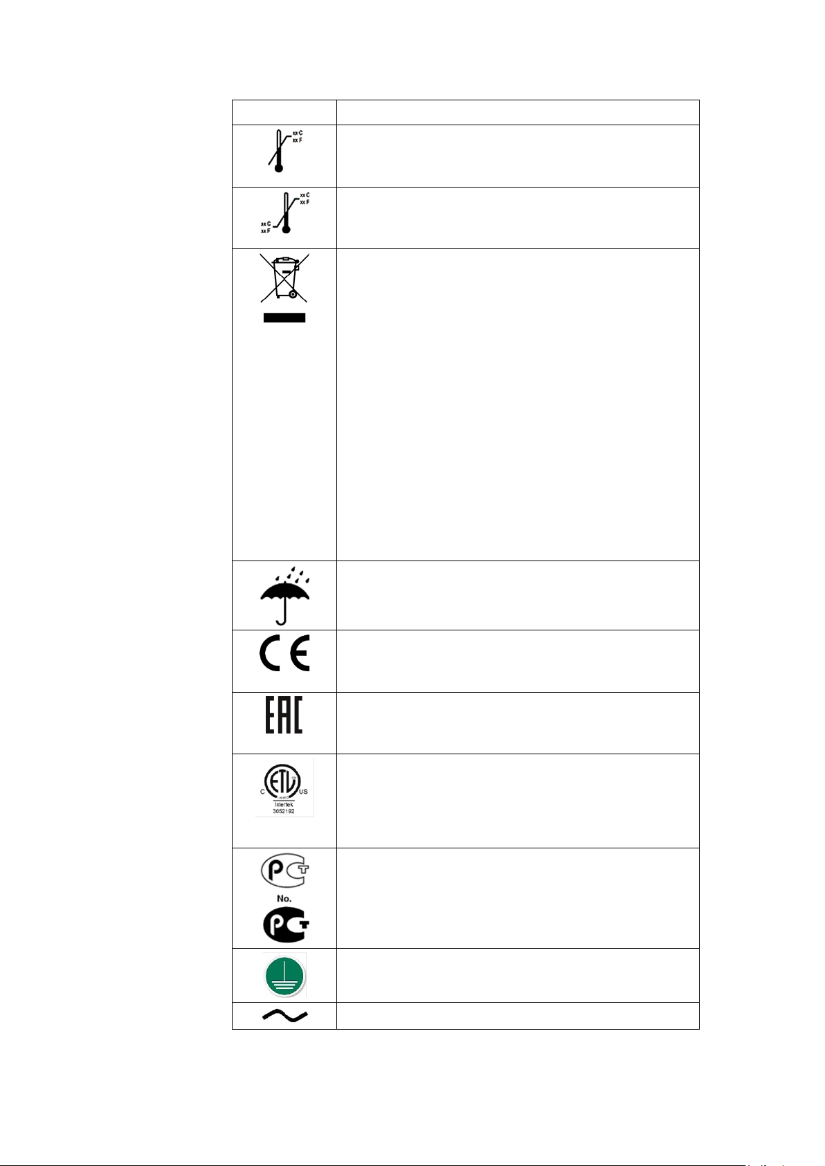
Symbol Description
Upper Temperature Limit
Indicates the maximum temperature for transportation
and handling of this package.
Temperature Limits
Indicates the upper and lower temperature limitations
for the transportation and handling of this package.
European Union Disposal Requirements
This equipment complies with the EU WEEE marking
requirement for proper disposal of electrical and
electronic waste in accordance with the European
Directive 2011/65/EE. This directive calls for separation
and recovery or reuse of used electrical or electronic
equipment upon end of life EEE disposal.
The T2100 must not be disposed of as unsorted
municipal waste. Electrical or electronic components
must be collected separately and disposed of in
accordance with your local requirements and sources.
The EEE program minimizes any potential effects on the
environment and user health by eliminating the
potential presence of hazardous substances in the waste
stream. Customers should contact their local authorities
or T2100 Distributor for guidance in complying with the
directive.
Introduction
Keep Dry
Indicates that you need to keep the container away from
rain and other sources of moisture.
CE Mark
Indicates the device or product conforms with
applicable EU (European Union) directives.
Eurasian Conformity mark
Conformity to applicable technical regulations of
Customs Union.
Electrical Testing Laboratories
Indicates the device or product has been tested by an
accredited third-party testing laboratory and meets
applicable safety standards for sale and distribution
within North America.
PCT (GOST-R) Mark
Indicates the device or product conforms with applicable
Russian Gosstandard technical and safety standards.
Protective earth (ground).
Alternating current.
2097937-002 Rev G T2100-ST1 Treadmill, 110V / T2100-ST2 Treadmill, 220V 21
11 March 2019
Page 22
Introduction
Symbol Description
Device is suitable for the external application of the type
“B” applied parts.
Unique Device Identification is a unique marking of the
medical device
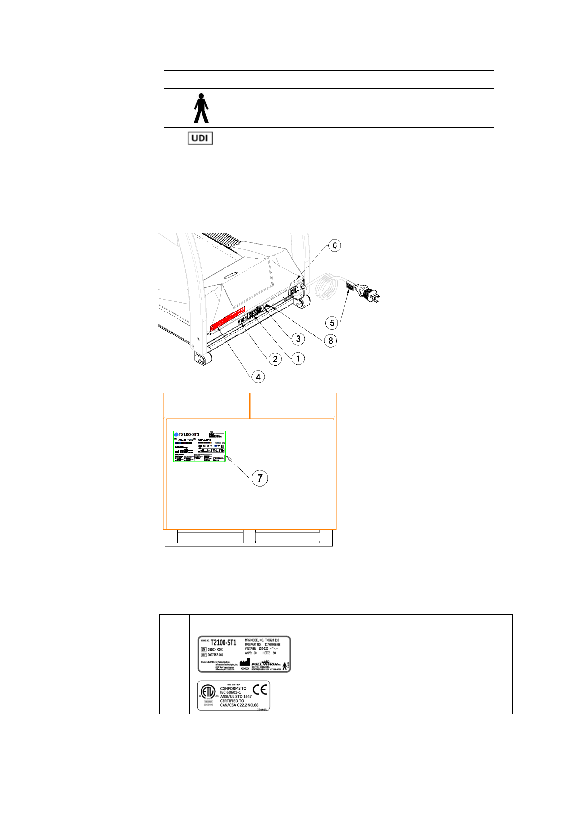
Label Locations
This section identifies the labels and their locations on the
product and packaging.
Refer to the previous illustrations for the locations of the labels
identified in the following table. For detailed descriptions of the
symbols that appear on the labels, refer to “Symbols” on page
20.
Item Label Location Description
1
Front of
device
Identifies the product
model.
2
22 T2100-ST1 Treadmill, 110V / T2100-ST2 Treadmill, 220V 2097937-002 Rev G
Front of
device
Identifies Listing Standards
11 March 2019
Page 23
Item Label Location Description
Introduction
3
4
5
6
7
Front of
device
Front of
device on
Hood
On Power
Cord
Front of
device
Shipping
Package
Contains the disposal.
Identifies the Caution
Electrical shock hazard.
Identifies DC Hi-Pot Caution.
Identifies Power switch.
Identifies the following
information for shipping:
• Model number
• Reference number
• Serial number
• Storage conditions
• Regulatory compliance
• Country of origin
• EC Representative
information
8
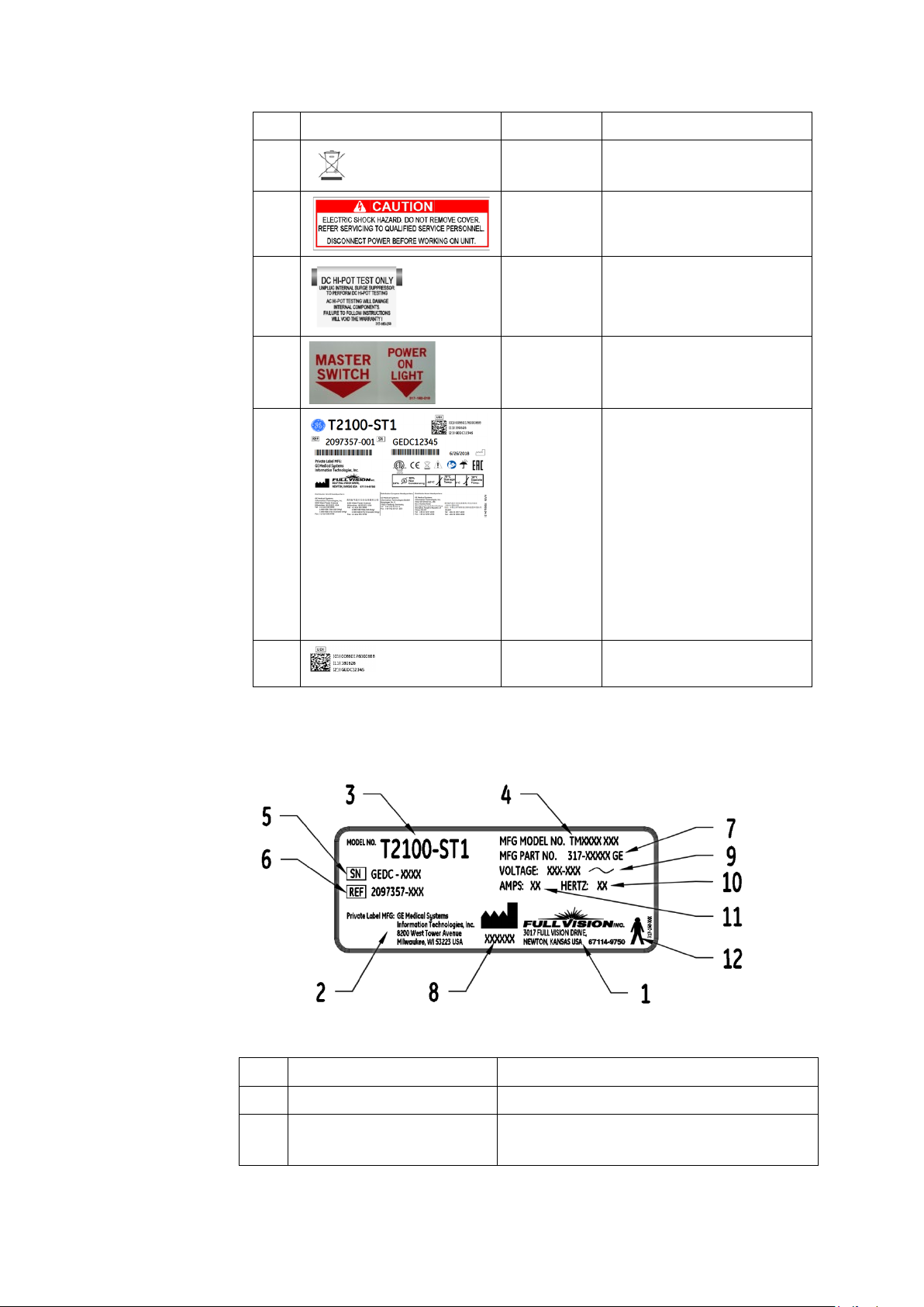
Equipment Identification
Product Label
Product Label Format
Item Name Description
1 Manufacturer Full Vision Inc.
Front of
device
Identifies Unique Device
Identifier
2 Private Label Manufacturer GE Medical Systems
Information Technologies, Inc
2097937-002 Rev G T2100-ST1 Treadmill, 110V / T2100-ST2 Treadmill, 220V 23
11 March 2019
Page 24

Introduction
Item Name Description
3 Model Number Identifies model of treadmill
Manufacturer Model
4
Number
5 Serial Number Manufacturer assigned serial number
6 REF GE Medical Systems reference part number
7 Manufacturer Part Number Manufacturing part number
8 Manufacturer Date Manufacturing date code
9 Voltage Specifies operating voltage of treadmill
10 Hertz Specifies the electrical hertz of treadmill
11 Amps Specifies amperage of treadmill
12 Type B Equipment Device is suitable for the external
Service Information
Identifies manufacturing model of treadmill
application of type “B” applied parts
This section provides information pertaining to the maintenance
and servicing of the system. Familiarize yourself with this
information before requesting service from GE Healthcare or its
authorized representatives.
Service Requirements
Failure on the part of the responsible individual, hospital, or
institution using this equipment to implement a satisfactory
maintenance schedule may cause undue equipment failure and
possible safety hazards.
Regular maintenance, irrespective of usage, is essential to
ensure that the components of this system are always functional
when required.
Warranty Information
This device is considered GE Healthcare-supplied hardware. Only
authorized GE Healthcare service personnel should service the
device. Any unauthorized attempt to repair equipment under
warranty voids that warranty. It is the user's responsibility to
report the need for service to GE Healthcare or to one of their
authorized agents.
Additional Assistance
GE Healthcare maintains a trained staff of application and
technical experts to answer questions and respond to issues and
problems that may arise during the installation, maintenance,
and use of this system.
Contact your local GE Healthcare representative to request
additional assistance.
24 T2100-ST1 Treadmill, 110V / T2100-ST2 Treadmill, 220V 2097937-002 Rev G
11 March 2019
Page 25

Manual Information
This section provides information for the correct use of this
manual.
Keep this manual with the equipment at all times and
periodically review it. You should request training assistance
from GE Healthcare, if needed.
Manual Purpose
This manual provides information necessary for the
configuration and safe operation of this equipment in
accordance with its function and intended use. It is not intended
as a replacement for, but a supplement to, thorough product
training. Keep it with the equipment at all times. Additional
manuals may be ordered by contacting GE Healthcare.
Document Conventions
This document uses the following conventions.
Introduction
Typographical Conventions
The following table identifies the typographical conventions used
in both this document and GE Healthcare Diagnostic Cardiology
product documents.
Convention Description
Bold Text Indicates keys on the keyboard, text to enter, or
hardware items such as buttons or switches on the
equipment
Italicized Bold
Text
KEY1+KEY2 Indicates a keyboard operation. A plus (+) sign between
<space> Indicates that you must press the spacebar. When
Indicates software terms that identify menu items,
buttons, or options in various windows.
the names of two keys indicates that while holding the
first key, you should press and release the second key.
For example, Press CTRL+ESC means to press and hold
the CTRL key and then press and release the ESC key.
instructions are given for typing a precise text string
with one or more spaces, the point where you must
press the spacebar is indicated as: <space>. This
ensures that the correct number of spaces are inserted
in the correct positions within the literal text string. The
purpose of the <> brackets is to distinguish the
command from the literal text within the string.
Enter
2097937-002 Rev G T2100-ST1 Treadmill, 110V / T2100-ST2 Treadmill, 220V 25
11 March 2019
Indicates that you must press the Enter or Return key
on the keyboard. Do not type Enter.
Page 26

Introduction
Convention Description
> The greater than symbol, or right angle bracket, is a
concise method to indicate a sequence of menu
selections.
For example, the statement “From the main menu,
select System > Setup > Options to open the Option
Activation window” replaces the following:
1. From the main menu, select System to open the
System menu.
2. From the System menu, select Setup to open
the Setup menu.
3. From the Setup menu, select Options to open
the Option Activation window.
Illustrations
All illustrations in the document are provided as examples only.
Notes
Notes provide tips or additional information that, while useful,
are not essential to the correct operation of the tools. They are
called out from the body text through a flag word and
indentation, as follows:
NOTE:
The tip or additional information appears indented below
the NOTE flag word.
Related Documents
The following documents are referenced in this manual and
provide additional information that may be helpful in the
installation, configuration, maintenance, and use of this product.
Part Number Title
2097937-001 T2100-ST1 /T2100-ST2 Operator’s Manual, English
2097937-021 T2100-ST1/T2100-ST2 Operator Manual, S. Chinese
2097937-051 T2100-ST1/T2100-ST2 Operator Manual, Danish
2097937-061 T2100-ST1/T2100-ST2 Operator Manual, Dutch
2097937-091 T2100-ST1/T2100-ST2 Operator Manual, French
2097937-131 T2100-ST1/T2100-ST2 Operator Manual, Indonesian
2097937-151 T2100-ST1/T2100-ST2 Operator Manual, Japanese
2097937-171 T2100-ST1/T2100-ST2 Operator Manual, Korean
2097937-211 T2100-ST1/T2100-ST2 Operator Manual, Portuguese Brazil
2097937-271 T2100-ST1/T2100-ST2 Operator Manual, Spanish
2097937-011 T2100-ST1/T2100-ST2 Operator Manual, Bulgarian
2097937-031 T2100-ST1/T2100-ST2 Operator Manual, Croatian
2097937-041 T2100-ST1/T2100-ST2 Operator Manual, Czech
26 T2100-ST1 Treadmill, 110V / T2100-ST2 Treadmill, 220V 2097937-002 Rev G
11 March 2019
Page 27

Introduction
Part Number Title
2097937-071 T2100-ST1/T2100-ST2 Operator Manual, Estonian
2097937-081 T2100-ST1/T2100-ST2 Operator Manual, Finnish
2097937-101 T2100-ST1/T2100-ST2 Operator Manual, German
2097937-111 T2100-ST1/T2100-ST2 Operator Manual, Greek
2097937-121 T2100-ST1/T2100-ST2 Operator Manual, Hungarian
2097937-141 T2100-ST1/T2100-ST2 Operator Manual, Italian
2097937-161 T2100-ST1/T2100-ST2 Operator Manual, Norwegian
2097937-181 T2100-ST1/T2100-ST2 Operator Manual, Polish
2097937-201 T2100-ST1/T2100-ST2 Operator Manual, Portuguese EU
2097937-191 T2100-ST1/T2100-ST2 Operator Manual, Romanian
2097937-221 T2100-ST1/T2100-ST2 Operator Manual, Russian
2097937-231 T2100-ST1/T2100-ST2 Operator Manual, Serbian
2097937-241 T2100-ST1/T2100-ST2 Operator Manual, Slovak
2097937-261 T2100-ST1/T2100-ST2 Operator Manual, Swedish
2097937-251 T2100-ST1/T2100-ST2 Operator Manual, Turkish
2097937-281 T2100-ST1/T2100-ST2 Operator Manual, Vietnamese
2097937-311 T2100-ST1/T2100-ST2 Operator Manual, Lithuanian
2097937-291 T2100-ST1/T2100-ST2 Operator Manual, Kazakh
2097937-301 T2100-ST1/T2100-ST2 Operator Manual, Latvian
2097937-321 T2100-ST1/T2100-ST2 Operator Manual, Slovene
2097937-331 T2100-ST1/T2100-ST2 Operator Manual, Ukrainian
2097937-002 Rev G T2100-ST1 Treadmill, 110V / T2100-ST2 Treadmill, 220V 27
11 March 2019
Page 28

Page 29
2
1
2 3 6 4 7
5
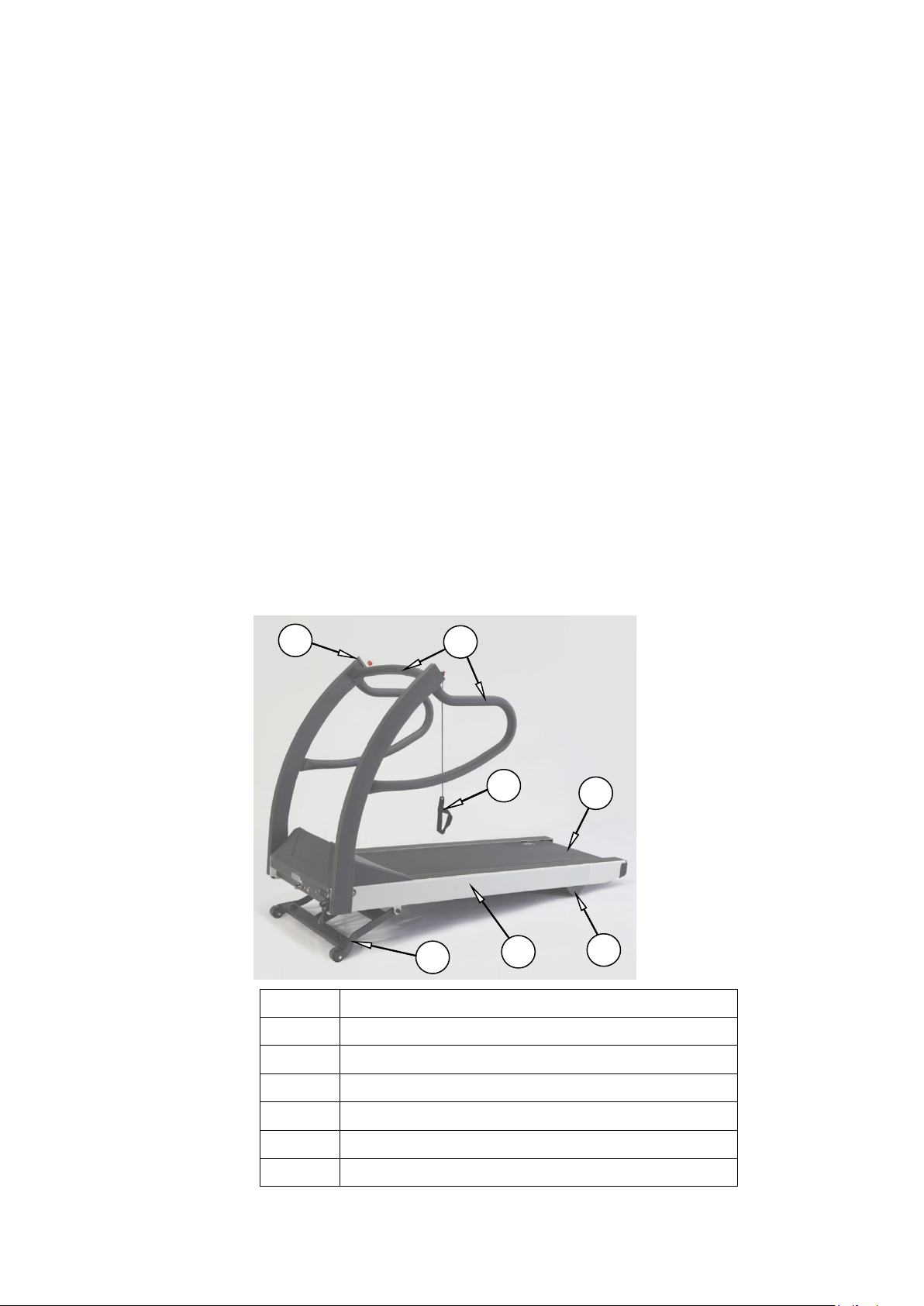
2 Product Overview
The T2100-ST1 and T2100-ST2 treadmills are designed and built
to withstand the extraordinary demands of medical devices and
are compatible with CASE, CardioSoft/CS, MAC 5500, and MAC
2000.
References to left, right, front, and rear assume that you are
standing on the treadmill, facing the handrails. All parts listed
below are considered Patient Applied Parts except where noted.
Item Description
2097937-002 Rev G T2100-ST1 Treadmill, 110V / T2100-ST2 Treadmill, 220V 29
11 March 2019
1 Emergency Stop Button
2 Patient Handrails
3 Stop Tether
4 Side Rail
5 Running Belt
6 Elevation Landing Gear (Non-Applied Part)
Page 30

Product Overview
Item Description
7 Rear Foot (Non-Applied Part)
Safety Systems
• Dual comparative speed sensors
• Auto runaway shutdown
• Auto communication loss shutdown
• Manual twist lock Emergency Stop button
• Manual Stop Tether
• Braking system for safe patient off-loading
• Fire-rated motor pan hood enclosure
Treadmill
• Patient weight capacity 500 lb., 227 kg
• All steel construction with powder-coat finish
• Treadmill net weight: 425 lb., 193 kg
Drive System
• Heavy-duty 6-peak hp. brushless, DC servo motor
• T2100-ST1 110-120VAC, single-phase, 60 Hz, 20-amp power
• T2100-ST2 200-240VAC, single-phase or split phase, 50-60
Speed Range
0.1 to 15.0 mph, 0.2 to 24.0 km/h, self-calibrating and adjustable
in 0.1 mph 0.1 km/h increments.
NOTE:
supply
Hz, 15-amp power supply
The T2100-ST2 maximum speed (15.0 mph) will deteriorate
at lower voltages (210VAC or below).
Incline Range
0 to 25%, 0.5% incremental movements, self-calibrating.
Running Surface
• 22in. x 63in. / 56cm x 160cm
30 T2100-ST1 Treadmill, 110V / T2100-ST2 Treadmill, 220V 2097937-002 Rev G
11 March 2019
Page 31

Product Overview
• MasterTrack® running belt tracking system
• Cushioned running deck absorbs shock of foot falls
• Self-lubricated and reversible running deck
• Step-up height (7 in. / 18cm from floor)
Communication Ports
• RS232 Female Serial port
• USB 1.0 “B” port
Floor Surface Footprint
33.0 in x 78.5 in, 84cm x 200cm level surface. (See “Location” on
page 37.)
Operating and Storage Condition Recommendations
• Operating Temperature Range: 4.5° to +38° C (+40° to +85°
F)
• Storage Temperature Range: -40° to +70° C (-40° to +158° F)
• Operating and Storage Relative Humidity Range: 10% - 90%,
non-condensing
• Altitude: -50 to 9,842 feet (-15m to 3000m); derate
performance by 5% per each additional 500 feet (152m)
above 5,280 feet (152m)
Power Requirements
The T2100-ST1 is designed to operate on dedicated 100-130 VAC
20-amp power, and the T2100-ST2 is designed to operate on
dedicated 200 to 264 VAC 13-amp power. Make sure that the
treadmill is connected to an outlet that looks like one of the
following illustrations.
• T2100-ST1 Power Consumption: 1934 watts (6600 BTU), 20
amps
• T2100-ST2 Power Consumption: 2580 watts (8804 BTU), 13
amps
This product is equipped with a three-wire grounding-type plug.
The plug will only fit into a grounding-type outlet. This safety
feature must not be disabled. Contact a qualified electrician if
you are unable to insert the plug into your outlet, or uncertain if
the outlet meets local electrical codes. Polarized outlets such as
NEMA 5-20, CEE7/7, and BS1363 must be verified for proper
polarity configuration before plugging in the T2100-ST1 or
T2100-ST2. Incorrect polarization of the outlet could cause
failure of onboard electrical components or cause electrical
2097937-002 Rev G T2100-ST1 Treadmill, 110V / T2100-ST2 Treadmill, 220V 31
11 March 2019
Page 32

Product Overview
110-120 VAC
220/240 VAC
230 VAC
220/240 VAC
250 VAC
230 VAC
240 VAC
250 VAC
240 VAC
250 VAC
250 VAC
250 VAC
shock. Proper grounding is necessary for the equipment to meet
acceptable current leakage standards consistent with the
standards to which it was certified.
NEMA 5-20R
Single Phase
Type N BRAZIL
GB 1002
NEMA 6-15R
Split Phase
Type H ISRAEL
BS1363
AS/NZS 3112
BS546 3 PIN
Type L ITALY
CEE 7/7 EURO
Type K DANISH
Type J SWISS
WARNING:
The T2100-ST1 and T2100-ST2 treadmills must be grounded
to reduce the risk of electrical shock. If a malfunction
occurs, grounding provides a path of least resistance for an
electric current. Ungrounded connections must not be
used.
No other equipment may be used on the electrical circuit
with the treadmills. Do not use extension cords. Using a
shared or unreliable circuit can also cause the treadmills to
unexpectedly shut off, potentially resulting in injury to the
patient.
Ensure the power switch is in the off position before
plugging in the T2100-ST1 or T2100-ST2. A power surge
could damage the sophisticated electronic system of the
treadmills.
32 T2100-ST1 Treadmill, 110V / T2100-ST2 Treadmill, 220V 2097937-002 Rev G
11 March 2019
Page 33

Product Overview
NOTE:
The T2100-ST1 and T2100-ST2 Treadmills must have their
own dedicated power outlet.
2097937-002 Rev G T2100-ST1 Treadmill, 110V / T2100-ST2 Treadmill, 220V 33
11 March 2019
Page 34

Page 35

3
3 Assembly and Setup
The T2100-ST1 and T2100-ST2 treadmills are shipped fully
assembled and packaged in a folded condition. They are
designed to pass through a standard 36” door opening
measuring at least 35½”. It will be necessary to remove the door
from the jam in most cases if the door is not capable of opening
fully parallel to door opening. After you have unpacked the
treadmill and secured the handrail assembly to the frame, move
the treadmill to the area by rolling it on its front wheels. If your
treadmill must pass through a door opening less than 36” wide,
additional disassembly by removal of the handrails is required.
Refer to “Removing and Reinstalling the Handrails for Moving” on
page 154. This task should be performed by an authorized
service provider to ensure that the T2100-ST1 and T2100-ST2 are
properly reassembled and functioning correctly.
Safe Handling Guidelines
2097937-002 Rev G T2100-ST1 Treadmill, 110V / T2100-ST2 Treadmill, 220V 35
11 March 2019
WARNING
The T2100-ST1 and T2100-ST2 treadmills each weigh 425
lbs. When lifting the rear of the treadmill and rolling it on
its front wheels, you are moving 132 lbs. This can be
accomplished by one person, but each installer must
evaluate whether he or she is capable of moving this
Page 36

Assembly and Setup
1 2 3 5 6
4
• Do not attempt to move the treadmill with the handrails in
• Lift the end of the bed assembly to a comfortable height,
• Rotate the treadmill in the direction you want to go (the
• When you have maneuvered the treadmill into its location,
amount of weight without causing strain or injury. If in
doubt, a second person should be recruited to assist.
If you are moving the treadmill over rough surface, such as
pavement, use a dolly under front of the treadmill to
prevent damage to the wheels and lift mechanism.
the shipping position due to the possibility of cutting the
internal wiring. You must either fully secure the handrails in
their proper position or secure handrails with 3/8-16 bolts
and 3/8 lock washers in the folded position.
keeping knees bent and back straight as you lift.
treadmill will pivot on its wheels) and push forward.
gently lower the end of the bed assembly to the floor.
Initial Setup
Tools required for assembly:
The treadmill is shipped with the handrails loose, straddling the
treadmill frame. It is advised that you secure the handrails in
their proper location before removing the treadmill from the
base of the crate. This prevents the internal wires running down
the handrail mount to the motor pan from being cut.
1. Swing the handrail assembly into the operating position
2. Install (2) plastic caps each side for a finished look.
• 5/16 Allen wrench (supplied)
and insert (2) 3/8-16 bolts and 3/8 lock washers on each
side and tighten securely.
36 T2100-ST1 Treadmill, 110V / T2100-ST2 Treadmill, 220V 2097937-002 Rev G
11 March 2019
Page 37

Item Description
1 Operating Position
2 Shipping Position
3 Insert (2) washer and bolts each side
4 Insert (2) caps each side
5 Pivot Point
Assembly and Setup
Location
6
When folding handrails apply cardboard between
frame and handrail to prevent handrail damage.
Place the T2100-ST1 or T2100-ST2 on a firm and level hard
surface that is free of tile grout lines. The illustration below
shows the minimum recommended clearances from the
treadmill edges to any obstruction for dismount and safety
purposes. Observe that the operator should be stationed by the
Emergency Stop Button (ESB).
WARNING:
The T2100-ST1 and T2100-ST2 treadmills conform to FCC
class B rating for electromagnetic emissions. It is
recommended not to place the treadmill closer than 5ft.
(1.5m) from sensitive electronic devices within the room or
in an adjacent room. If an interference problem occurs,
move the treadmill farther away from the sensitive device
or relocate either device to another area, or consult with an
EMI specialist for ways to shield the room from
electromagnetic radiation.
Do not place it on thick or long-pile carpeting. Such
carpeting could cause instability or static build-up, and
2097937-002 Rev G T2100-ST1 Treadmill, 110V / T2100-ST2 Treadmill, 220V 37
11 March 2019
Page 38

Assembly and Setup
carpet fibers could get caught in the belt and damage the
unit.
Ensure that power cords do not cross traffic areas. Exposed
power cords can cause a fall, resulting in injury.
Keep it away from sources of moisture, such as spas or
fountains. Moisture can cause the electronic circuitry to
malfunction.
Electrical Safety Tests
Except where noted, the following electrical safety tests are
optional at the time of install.
You must conduct the following electrical safety tests after any
service is performed or if the hood was removed.
AC Line Voltage Test
This test verifies that the wall outlet supplying power to the
equipment is properly wired. For international wiring test, refer
to the internal standards agencies of that particular country.
NOTE
The AC Line Voltage test is required at the time of
installation.
100 to 130 VAC, 60 Hz
Using a digital voltmeter set to measure at least 200 VAC to
check the voltage of the NEMA 5-20R AC wall outlet (U.S. only or
applicable international connection; dedicated 20-amp service).
If the measurements are out of range, have a qualified
electrician repair the outlet. The voltage measurements should
be:
100 to 130 nominal VAC between the “neutral” and “hot”
contacts.
200 to 264 VAC, 50/60 Hz
Using a digital voltmeter set to measure at least 300 VAC to
check the voltage of the NEMA 6-15R AC wall outlet (U.S. only or
applicable international connection; dedicated 13-amp service).
If the measurements are out of range, have a qualified
electrician repair the outlet. The voltage measurements should
be:
38 T2100-ST1 Treadmill, 110V / T2100-ST2 Treadmill, 220V 2097937-002 Rev G
11 March 2019
Page 39

Assembly and Setup
200 to 264 nominal VAC between the two “hot” contacts.
Power Cord and Plug
Verify the power cord being used with the treadmill is good:
• Verify that the line, neutral (if applicable), and ground
conductors are properly connected to the power cord plug
and are not short-circuited. Replace the power cord if
necessary.
• Failure of the power cord strain relief is very common.
Often users of the equipment pull on the power cord itself,
rather than the power cord plug, to unplug the unit from a
wall receptacle. If in doubt, test for continuity through
each.
• Perform the Ground Continuity Test, below, or the test
method that is required by your Country/Local governing
safety organization. For international power cords, refer to
the internal standards agencies of that particular country.
Ground Continuity Test
This test verifies that there is continuity (less than 100 mΩ
resistance) between exposed metal surfaces, which have the
potential to become energized, and the ground prong on the
mains AC power cord. Look for an exposed metal screw, or, if the
metal surfaces are anodized or painted, scrape off a small area
in an inconspicuous area on the aluminum casting, for the probe
to make direct contact with the metal.
1. Disconnect the power cord from wall outlet with the T2100ST Series treadmill power switch in the “ON” position.
2. Use a digital multimeter to check metal surfaces of the
equipment as illustrated below. Make adjustments for any
resistance in the test leads.
2097937-002 Rev G T2100-ST1 Treadmill, 110V / T2100-ST2 Treadmill, 220V 39
11 March 2019
Page 40

Assembly and Setup
Conducting Leakage Tests
The leakage tests are safety tests to ensure that the equipment
poses no electrical health hazards. Use the table below to
determine which tests apply to the unit under test and the
maximum allowable leakage currents. For international leakage
limits, refer to the internal standards agencies of that particular
country.
If the measurements are significantly out of range, check
for breaks in the power cord or in the internal connections
within the units.
If the unit under test fails the leakage tests, do not allow the
customer to use the equipment. Call Tech Support for assistance.
GE Healthcare recommends that you perform these tests:
• Before applying power for the first time
• Whenever internal assemblies are serviced
NOTE:
The accuracy of the leakage tests depends on a properlywired wall outlet. Do not proceed until you verify the
integrity of the power source.
40 T2100-ST1 Treadmill, 110V / T2100-ST2 Treadmill, 220V 2097937-002 Rev G
11 March 2019
Page 41

Assembly and Setup
Earth/Chassis Leakage Current to Ground
1. Forward Polarity (L1, L2) NC _________μA Pass/Fail 500μA
2. Neutral (L2) open,
Forward Neutral Polarity
3. Ground open, Forward Polarity SFC _________μA Pass/Fail 500μA
4. Ground open, Reverse Polarity SFC _________μA Pass/Fail 500μA
5. Neutral (L2) open,
Reverse Polarity
6. Reverse Polarity (L2, L1) NC _________μA Pass/Fail 500μA
SFC _________μA Pass/Fail 500μA
SFC _________μA Pass/Fail 500μA
Ground Continuity
1.
AC mains power cord ground
prong to exposed metal surface
(ground lug)
N/A
Pass/Fail 100mΩ
________mΩ
limits
Resistance
WARNING:
Total system leakage current must not exceed 500
microamperes.
Leakage Test Diagrams
These diagrams show only a representation of how a typical
leakage current tester functions. Follow the instructions
provided with the leakage current tester that you use.
Test #1
Ground-Wire-Leakage-to Ground
Make sure the UUT power switch is in the ON state without
running belt running.
Test #2
Chassis-Leakage-to-Ground (Exposed Chassis)
Make sure the UUT is in the ON state with running belt running at
2.0mph.
2097937-002 Rev G T2100-ST1 Treadmill, 110V / T2100-ST2 Treadmill, 220V 41
11 March 2019
Page 42

Assembly and Setup
Secure Cables
Tie down cables to ensure they do not get caught in the wheels
or the elevation racks.
Running Belt Tracking Adjustment
NOTE:
This adjustment is not covered under your warranty after
installation. It is important that you review these
instructions thoroughly before proceeding with belt
tracking adjustment. Uneven floors accelerate belt
misalignment. This situation may require more frequent
adjustment to prevent belt damage.
The patented MasterTrack® Belt Tracking System significantly
reduces the need to adjust the belt on your T2100-ST1 or T2100ST2 treadmill. However, when you operate your treadmill for the
first time, you may need to adjust the tracking of the belt to
conform to your floor. You may also need to adjust the tracking if
you move the machine to another location. (See “Running Belt
Tracking Adjustment” on page 59 for details.)
Running Belt Tension Adjustment
Your running belt has been pre-tensioned at the factory and run
for 16 hours prior to shipment. It may, however, be necessary to
adjust the belt tension when the treadmill is run in its final
location. A loose belt tends to hesitate or stick with a heavy foot
plant. If your belt needs tensioning, the adjustment procedure
can be found in “Running Belt Tension Adjustment” on page 60.
NOTE:
Improper adjustment could cause the treadmill to hesitate
and cause a trip and fall hazard. This adjustment is not
covered under your warranty after installation. It is
important that you review these instructions thoroughly
before proceeding.
42 T2100-ST1 Treadmill, 110V / T2100-ST2 Treadmill, 220V 2097937-002 Rev G
11 March 2019
Page 43

Drive Belt Tension Adjustment
1
4
2
3
The drive belt tension has been pre-set at the factory to
minimize maintenance. If there are indications that the drive belt
has stretched and become loose, refer to "Drive Belt Tension
Adjustment" on page 60. Symptoms of a stretched drive belt
could include increased noise.
Test Plug Procedure
Each T2100-ST1 and T2100-ST2 treadmill includes an RS-232 test
plug that enables you to test the operation of the treadmill
without the host controlling device attached. The plug is located
on the left side of the treadmill secured to the frame by Velcro®.
The plug is to be used only for testing the treadmill. Do not stand
on or use the treadmill while testing.
Assembly and Setup
Item Description
1 Test Plug Location on Left
2 Circuit Breaker Array
3 Incoming Power Cord
4 Main Power Switch
Communication Ports
The communication ports are located at the very front of the
treadmill near the center of the unit.
Two ports are offered with equal communication capability. The
standard female RS232 port and a USB Type B port offer
connectivity diversification.
2097937-002 Rev G T2100-ST1 Treadmill, 110V / T2100-ST2 Treadmill, 220V 43
11 March 2019
Page 44

Assembly and Setup
2
1
Item Description
1 RS232 Port “Female”
2 USB “B” Port
Using the test plug
1. Turn the power "OFF" at the treadmill.
2. If connected, remove the RS232 or USB interface cable from
the treadmill and plug in the test connector into the RS232
port.
3. Press and hold the button on the test connector and turn
the treadmill power "ON". Continue holding until the
treadmill begins to elevate.
4. When the treadmill begins to raise, repeatedly press the
button to cycle through the different phases of the test.
The following table shows the sequence of self-test stages:
Stage Incline Speed (mph)
1 5% 0.0
2 10% 0.0
3 15% 0.0
4 20% 0.0
5 20% 1.0
6 20% 2.5
7 20% 5.0
8 20% 7.5
9 20% 10.0
10 15% 7.5
11 10% 5.0
12 5% 2.5
44 T2100-ST1 Treadmill, 110V / T2100-ST2 Treadmill, 220V 2097937-002 Rev G
11 March 2019
Page 45

Stage Incline Speed (mph)
13 0% 1.0
14 0% 0.0
NOTE:
Successful completion of the preceding testing
procedure ensures that the treadmill is fully
functional and responsive to command signals.
NOTE:
Unsuccessful completion of the preceding testing
procedure indicates a problem with the setup. Call GE
Medical Systems Information Technologies to trouble
shoot failure of test plug procedure.
5. Turn the power "OFF" at the treadmill.
6. Remove the test connector.
Assembly and Setup
7. Reconnect the RS232 or USB interface cable from the host
computer.
You are ready to begin the set-up procedure prescribed by
your medical test equipment supplier.
Setup and Connection to Host
Currently, four GE host stress systems can connect to the T2100ST series treadmill and are used as controlling devices: CASE
CardioSoft/CS, MAC 5500, and MAC 2000.
CASE connection and setup:
1. Connect one end of the RS232 serial cable (GE part number
2097829-109) to the RS232 COM port located on the lower
front panel of the T2100-ST series treadmill and run it
through the communication cable clamp, as shown in the
following photograph.
2. Connect the other end of the RS232 serial cable (GE part
number 2097829-109) to a COM port on the CASE unit (it is
suggested to use COM1 or COM2).
2097937-002 Rev G T2100-ST1 Treadmill, 110V / T2100-ST2 Treadmill, 220V 45
11 March 2019
Page 46

Assembly and Setup
3. Make sure the treadmill is connected to AC power and
4. If necessary, turn on CASE with the power button on the
5. Log in when prompted.
6. If not already in the software application, double-click the
Referencing the CASE rear I/O connector panel label, take
note of the COM port number plugged into.
turned on.
side panel.
The program will start up automatically and the Windows
screen opens.
Refer to the CASE Operator’s Manual for logon instructions.
CASE icon.
The CASE initial screen opens.
CASE Initial Screen
NOTE:
Depending on the version of software and user
preferences, the initial screen will vary.
7. On the upper right side of the screen, click the System
Configuration button.
Depending on the version of software the button may look
like one of the following:
The System Configuration window opens.
8. Click the Devices tab.
46 T2100-ST1 Treadmill, 110V / T2100-ST2 Treadmill, 220V 2097937-002 Rev G
11 March 2019
Page 47

Assembly and Setup
The COM port number is displayed in the Port field, as
shown in the following screen.
9. Ensure the Treadmill Model is set to T2100.
10. Ensure the COM port number is set to the one physically
connected to in step 2, above, and, if necessary, change to
match.
11. Click OK to close the System Configuration window and
return to the CASE initial screen.
If needed, the CASE device operating instructions should be
referenced for controlling the treadmill with the CASE
application.
CardioSoft/CS connection and setup:
To communicate to the T2100-ST1 or T2100-ST2 treadmill using
the USB port, you will need to install the appropriate USB driver
software on your host computer. The USB driver is supplied on
the provided flash drive. When connecting to the USB port,
ensure port configuration is congruent with your software port
identification.
First Time Installation of the Serial Driver Software on the CardioSoft/CS PC
This section installs the USB Serial Driver on the PC which has the
CardioSoft or CS application installed.
2097937-002 Rev G T2100-ST1 Treadmill, 110V / T2100-ST2 Treadmill, 220V 47
11 March 2019
Page 48

Assembly and Setup
NOTE:
1. If necessary, turn on the CardioSoft/CS PC and log on when
2. Locate the flash drive (PN 317-160-313) shipped with the
3. Browse the flash drive and locate the file named
Do not plug any hardware, including the treadmill USB
cable, into the CardioSoft/CS PC until directed to do so.
prompted.
Refer to the CardioSoft/CS Operator Manual for logon
instructions.
T2100-ST series treadmill and insert into a USB port of the
CardioSoft/CS PC.
CDM21218_Setup.exe and double-click it to start the
installation.
NOTE:
Do not download the driver from the FTDI website.
NOTE:
The following instructions are for a PC running
Windows 7. The basic instruction flow should be the
same for Windows 8 and 10, although the screens
may vary. If necessary, refer to Appendix B,
“Reference Documents”, for a list of reference
documents that contain helpful OS-specific guidance.
4. If you receive the prompt “Do you want to allow the
following program to make changes to this computer?”,
verify the program name, CDM21218_Setup.exe, and
publisher, Future Technology Devices International Ltd,
and click Yes.
The Driver Extract window opens.
48 T2100-ST1 Treadmill, 110V / T2100-ST2 Treadmill, 220V 2097937-002 Rev G
11 March 2019
Page 49

Assembly and Setup
5. Click Extract.
The Device Driver Installation Wizard opens.
6. Click Next.
The License Agreement window opens.
2097937-002 Rev G T2100-ST1 Treadmill, 110V / T2100-ST2 Treadmill, 220V 49
11 March 2019
Page 50

Assembly and Setup
7. Select I accept this agreement and click Next.
An installation progress window opens.
The installation process should take less than a minute.
When the installation is complete, the Device Driver
Installation Wizard window opens confirming a successful
installation.
50 T2100-ST1 Treadmill, 110V / T2100-ST2 Treadmill, 220V 2097937-002 Rev G
11 March 2019
Page 51

Assembly and Setup
8. To close the window, click Finish.
Communication Port Identification and CardioSoft/CS setup
1. Connect a USB cable (GE part number 2044095-001)
between the CardioSoft/CS PC and the T2100-ST series
treadmill.
2. Connect AC power to the treadmill.
3. Power on the treadmill.
4. If necessary, turn on the CardioSoft/CS PC and the monitor.
5. On the CardioSoft/CS PC, determine the COM port that the
USB Serial Port is using by doing the following:
a. On the CardioSoft/CS PC click Start and in the Search
programs and files field, type: Device Manager and
press Enter.
The Device Manager window opens.
b. Scroll to Ports (COM & LPT).
c. Find the USB Serial Port in the list
The port number is given in the parenthesis.
NOTE:
This may take a minute or so to display.
d. Make note of this port and port number, you will use it
later when selecting the COM port in the System
Configuration window of the CardioSoft/CS
application software.
2097937-002 Rev G T2100-ST1 Treadmill, 110V / T2100-ST2 Treadmill, 220V 51
11 March 2019
Page 52

Assembly and Setup
6. If not already in the software application, double-click the
e. Close Device Manager window.
CardioSoft or CS icon.
The CardioSoft or CS initial screen opens.
CardioSoft Initial Screen
NOTE:
Depending on the version of software and user
preferences, the initial screen will vary.
7. On the upper right side of the screen, click the System
Configuration button.
Depending on the version of software the button may look
like one of the following:
The System Configuration window opens.
8. Click the Devices tab.
9. The COM port number is displayed in the Port field, as
shown in the following screen.
52 T2100-ST1 Treadmill, 110V / T2100-ST2 Treadmill, 220V 2097937-002 Rev G
11 March 2019
Page 53

Assembly and Setup
10. Ensure the Treadmill Model is set to T2100.
11. Ensure the COM port number is set to the port number as
identified in step 5.d, above.
If necessary, change the number to match.
12. Click OK to close the System Configuration window and
return to the CardioSoft or CS initial screen.
If needed, the CardioSoft/CS operating instructions should
be referenced for controlling the treadmill with the CASE
application.
MAC 5500 ST connection and setup:
NOTE:
Prior to starting this section, confirm the MAC 5500 device
contains the ST (Stress Test System) option. The device can
be identified by the two additional rows of keys on the
keyboard, as shown (1) in the following illustration.
2097937-002 Rev G T2100-ST1 Treadmill, 110V / T2100-ST2 Treadmill, 220V 53
11 March 2019
Page 54

Assembly and Setup
1. Turn the power OFF at the treadmill.
2. Connect the 9-pin D-Sub end of the communication cable
3. Connect the 8-pin mini DIN of the communication cable (GE
MAC 5500 ST (Keyboard)
(GE part number 2097829-108) to the RS232 COM port
located on the lower front panel of the treadmill.
part number 2097829-108) to the COM1 port on the
MAC 5500 ST unit.
MAC 5500 Rear View
4. Make sure the treadmill is connected to AC power.
5. Turned the power ON at the treadmill.
6. If necessary, turn on the MAC 5500 ST device with the
power button on the keyboard.
Refer to the MAC 5500 operator’s manual for instructions
on conducting an exercise stress test.
MAC 2000 ST connection and setup:
NOTE:
Prior to starting this section, confirm that the MAC 2000
device contains the ST (Stress Test System) option. The
device can be identified by the two additional rows of keys
on the keyboard, as shown (1) in the following illustration.
54 T2100-ST1 Treadmill, 110V / T2100-ST2 Treadmill, 220V 2097937-002 Rev G
11 March 2019
Page 55

Assembly and Setup
MAC 2000 ST (Keyboard)
1. Turn the power OFF at the treadmill.
2. Connect one end of the RS232 serial cable (GE part
number 2097829-110) to the RS232 COM port located on
the lower front panel of the treadmill.
3. Connect the other end of the RS232 serial cable (GE part
number 2097829-110) to the COM B port on the MAC 2000
ST unit.
MAC 2000 Rear View
4. Make sure the treadmill is connected to AC power.
5. Turn the power ON at the treadmill.
6. If necessary, turn on MAC 2000 ST with the power button
on the keyboard.
Refer to the MAC 2000 operator’s manual for instructions
on conducting an exercise stress test.
2097937-002 Rev G T2100-ST1 Treadmill, 110V / T2100-ST2 Treadmill, 220V 55
11 March 2019
Page 56

Page 57

4
4 Preventive Maintenance
Regular cleaning and maintenance is essential to keep your
T2100-ST1 and T2100-ST2 treadmills operating at their best for
many years. We recommend that you record all maintenance
and service in a log (as shown in Appendix A).
CAUTION
Before cleaning the T2100-ST1 and T2100-ST2 treadmills,
turn the main power switch to OFF, and disconnect the
treadmill from its power outlet. Never use wet cleaning
materials near a power source.
To preserve the condition of your warranty, make sure that all
repair procedures (other than normal maintenance) are
performed by an authorized and qualified service provider.
Contact your local GE customer support representative.
Use only authorized replacement parts. Using other parts may
void your warranty and may cause your T2100-ST1 or T2100-ST2
treadmill to malfunction.
Daily Maintenance
• Wipe the treadmill to remove soil, moisture, and
perspiration.
• Disinfect the hood and handrails with a soft cloth, dampened
with a solution of containing up to 70% alcohol.
• Remove stubborn stains and scuff marks with a nonabrasive,
industrial strength cleaner, such as Formula 409®. Spray all
2097937-002 Rev G T2100-ST1 Treadmill, 110V / T2100-ST2 Treadmill, 220V 57
11 March 2019
cleaners on a terrycloth-type cloth (avoid spraying cleaner
directly onto the treadmill).
• Ensure that the treadmill is functioning properly.
• Visually inspect the treadmill and walking belt for damage
and wear.
Page 58

Preventive Maintenance
• Press the Emergency STOP Button (ESB) and the treadmill
will coast to a stop. To release the emergency stop switch,
turn the push button ¼-turn in counter clockwise direction.
The treadmill will return to 0.0% elevation.
• Pull the Safety Tether System (STS) and the treadmill will
have a controlled stop. To re-attach the pull tether, attach
clip to the original position on the switch. The treadmill will
return to 0.0% elevation.
Weekly Maintenance
• Vacuum around and under the treadmill. Clean all exposed
surfaces with a vacuum cleaner. Avoid moving the treadmill
from its original position as moving it will compromise the
original belt tracking setting.
• Check running belt tension.
• Observe running belt tracking and correct as required.
Monthly Maintenance
Inspect and clean the running belt.
Semiannual Maintenance
• Evaluate the condition of the deck and running belt.
• Adjust the running belt to assure proper alignment.
• Check the running belt adjustment.
• Check the drive belt tension adjustment.
• Clean and lubricate the treadmill elevation screw.
• Clean the interior of the motor electrical enclosure as
needed.
Belt Cleaning and Inspection
1. Turn the treadmill main power switch ON.
2. Start treadmill at 0.5 mph (0.8 km/h).
3. With a damp small towel wipe excessive dirt from running
belt keeping the towel in the center of the length of the
treadmill. Avoid getting the towel near the rear roller.
4. When belt is clean, stop the treadmill.
5. Inspect the running belt for tears or nicks. If damaged,
replace the belt.
6. Perform the Running Belt Tracking Adjustment and Belt
Tension Adjustment.
58 T2100-ST1 Treadmill, 110V / T2100-ST2 Treadmill, 220V 2097937-002 Rev G
11 March 2019
Page 59

Running Belt Tracking Adjustment
This procedure requires the following tool:
¼” Allen wrench
NOTE:
Because this adjustment is not covered under your
warranty, it is important that you review these instructions
thoroughly before proceeding.
The patented MasterTrack® Belt Tracking System significantly
reduces the need to adjust the belt on your T2100-ST1 or T2100ST2 treadmill. However, when you operate your T2100-ST1 or
T2100-ST2 treadmill for the first time, you may need to adjust
the tracking of the belt to conform to your floor. You may also
need to adjust the tracking if you move the machine to another
location.
Your running belt should remain centered, although a slight
amount of movement to the left or right is normal during use. Do
not allow the running belt to travel all the way to either side.
Preventive Maintenance
To adjust the belt tracking, do the following:
1. Turn the treadmill’s power switch to ON.
2. Increase the speed to 3 mph (4.8 km/h)
3. Observe the left side of the running belt as it travels over
the rear roller. If the belt runs to the right side of the roller,
turn the right bolt 1/8 turn clockwise, and turn the left bolt
1/16 turn counterclockwise.
NOTE:
When tightening one side of the belt, always loosen
the opposite side one-half as much. This procedure
provides finer control, with a smaller impact on the
belt tension.
Check the belt after 2 minutes, with the treadmill running
at approximately 7 mph (11.3 km/h). If the belt does not
correct itself, continue with slight turns until the belt is in
the center of the rear roller. If the belt runs toward the left
side of the roller, reverse the adjustments.
NOTE:
Uneven floors accelerate belt misalignment. This
situation may require more frequent adjustment to
prevent belt damage.
2097937-002 Rev G T2100-ST1 Treadmill, 110V / T2100-ST2 Treadmill, 220V 59
11 March 2019
Page 60

Preventive Maintenance
1
NOTE:
When operating the treadmill at a High Speed Application
may cause hesitation/slippage of the running belt with
each foot plant. This could be a sign of the backing of the
running belt breaking down causing a premature failure.
For troubleshooting refer to “Running Belt High Speed
Application” on page90.
Item Description
1 Adjustment Bolts
Running Belt Tension Adjustment
The running belt may stretch and loosen with regular use. This
looseness is noticeable when the belt tends to hesitate or stick.
Adjust the tension on the belt by following the procedure and
referring to the illustration above.
1. Turn the treadmill’s power switch to ON.
2. Start the treadmill and increase to 1 mph (1.6 km/h).
3. Start walking on the treadmill, grabbing side handrail and
applying pressure with your foot to create resistance on
the running belt.
4. If the running belt hesitates or slips on the front drive roller,
tighten both tension bolts ½ turn (clockwise).
5. Repeat steps 2 through 4 until the running belt stops
slipping.
NOTE:
When the running belt is too tight, the edge of belt
will curl, causing premature running belt failure.
Drive Belt Tension Adjustment
This procedure requires the following tool:
1
•
60 T2100-ST1 Treadmill, 110V / T2100-ST2 Treadmill, 220V 2097937-002 Rev G
/8” Allen Wrench
11 March 2019
Page 61

Preventive Maintenance
1 2 3
• ¾” Socket or Box Wrench
• ¾” Wrench
• Tape measure
NOTE:
The drive belt may stretch and loosen with regular use. This
looseness may result in a flapping noise under the hood.
If there are indications that the drive belt has stretched and
become loose, contact your in-house biomedical
technician, or contact GE Medical Systems Information
Technologies, Inc., and open a customer service call.
1. Remove the (5) #10-32 screw located on the bottom hood
with 1/8” Allen wrench.
2. With the ¾” socket and wrench loosen the TENSION
ADJUSTMENT back nut.
3. Press down on drive belt between motor and front roller
with approximately 5lbs of force to achieve ¼” to 3/8”.
4. If adjustment is need using a ¾” wrench turn the TENSION
BOLT clockwise to tighten. To loosen, turn the wrench
counter clockwise.
5. Make small adjustment until the drive belt deflects
approximately ¼” to 3/8”, tighten the TENSION
ADJUSTMENT back nut.
NOTE:
Failure to lock the TENSION ADJUSTMENT back nut
will allow the drive belt tension to become loose.
6. When the treadmill is properly adjusted, reinstall the hood
with (5) #8-32 screws.
Item Description
1 ¼ to 3/8 Deflection
2 5 lbs down force
2097937-002 Rev G T2100-ST1 Treadmill, 110V / T2100-ST2 Treadmill, 220V 61
11 March 2019
Page 62

Preventive Maintenance
NOTE:
Exterior Care
The powder-coat finish on your T2100-ST1 or T2100-ST2
treadmill is an extremely durable finish and requires minimal
care. Do not allow perspiration to build up on your treadmill.
Wipe the unit daily.
• Use a moist cloth to wipe the surface clean; do not
3 Tension adjustment back nut
When drive belt is over-tensioned, the belt tension will
cause motor noise. This could result in premature
motor life failure.
allow liquids to enter the system. All cleaning agents
and disinfectants used in hospitals and containing up
to 70% alcohol are suitable. If liquids have entered the
system, notify service to have the system inspected for
damage before it is used again.
• DO NOT use disinfection with a phenol base or peroxide
compound to disinfect the external surface.
Elevation Screw Lubrication
The Elevation Screw must be cleaned and lubricated every 6
months to maintain proper operation of the treadmill. Failure to
perform this maintenance function will result in premature wear
and ultimate failure of the lift mechanism.
This procedure requires the following tools:
• Service Grease, 6oz tube (GE part number 2097829-072)
• Clean, lint-free cloth
• Small paint brush
1. Raise the treadmill to its maximum elevation.
2. Turn the main power switch to the OFF position, and unplug
the treadmill from its outlet.
3. Using a lint-free cloth, remove the old lubricant and
accumulated dust from the elevation screw.
4. Use a small brush to reapply a thin coat of grease to the
threads of the elevation screw. Do not use too much grease
(less than 1 ounce required)—the excess could squeeze onto
the floor and create a slip-and-fall hazard.
5. Return the unit to service.
62 T2100-ST1 Treadmill, 110V / T2100-ST2 Treadmill, 220V 2097937-002 Rev G
11 March 2019
Page 63

Running Deck Maintenance
The treadmill’s running deck is maintenance–free and offers two
running deck surfaces for double the life of ordinary treadmills.
NOTE:
Do not use any silicone or lubricating sprays during
preventative maintenance on your treadmill deck. Using
such sprays may void the warranty. Using such sprays can
bring about surface changes that may result in hesitation
or excessive belt slip.
Prolonged use in high speed running may cause
hesitation/slippage on each foot plant. Inspect the running
deck for factory lubrication on running surface. For
troubleshooting refer to “Running Belt High Speed
Application” on page90.
If the running deck surface becomes grooved due to wear,
it can be renewed by flipping the deck to the opposite side.
Notify your in-house biomedical technician, or contact GE
Medical Systems Information Technologies, Inc., and open a
customer service call.
Preventive Maintenance
2097937-002 Rev G T2100-ST1 Treadmill, 110V / T2100-ST2 Treadmill, 220V 63
11 March 2019
Page 64

Page 65

5
5 Theory of Operation
The T2100-ST1 / T2100-ST2 Universal Power Supply (UPS)
treadmill control provides a means of controlling belt speed and
elevation for the treadmill through the use of either an RS-232
serial port or USB port. The communication protocol is based on
the industry standard. In addition to the physical interfaces with
the controlling system (PC), the motor controller and elevation
motor, the UPS also includes an interface to an emergency stop
switch and an SD card.
Scope
This chapter applies only to the electronic control for the T2100ST1 and T2100-ST2 treadmills. Specifications for the mechanical
treadmill, elevation motor assembly, belt motor, and motor
controller are not covered.
2097937-002 Rev G T2100-ST1 Treadmill, 110V / T2100-ST2 Treadmill, 220V 65
11 March 2019
Page 66

Theory of Operation
T2100-ST Series Block Diagram
4th Edition Smart Power Supply FGLF0495-3
3.1 Edition Smart Power Supply FGLF0495-1
66 T2100-ST1 Treadmill, 110V / T2100-ST2 Treadmill, 220V 2097937-002 Rev G
11 March 2019
Page 67

Smart Power Supply (PCB) Overview
When power is applied to the unit, the UPS reads the contents of
the non-volatile memory and verifies the calibration contents
with a checksum. If the contents are not valid, the calibration
constants are set to non-operational values and the unit is put
into a state where operation is suspended pending recalibration.
If the contents are valid, the unit enters a startup mode where
the system checks to see if it should enter self-test mode
(described in the “Self-Test Mode” on page 70) and begins to find
the zero elevation point by turning on the elevation motor in the
down direction. If motion is not detected for two seconds, the
system assumes that the lower elevation limit has been reached.
During the “elevation zeroing” time, if a command to start the
belt is received from the PC, it is assumed that the PC is not
aware of the UPS power cycle and the unit will enter a nonresponsive state (waiting for either a communication timeout or
a stop command). If the elevation limit is found without receiving
a start belt command, the UPS enters the operational mode with
a set speed and set elevation of zero.
Theory of Operation
In operational mode, the unit continuously controls the belt
speed output, the belt-enable output, and the outputs to raise or
lower the elevation based on the current set points for speed and
elevation. Through the use of either communication port, the
unit accepts commands to modify the belt state, the belt speed,
and the deck elevation. The current state of the control may also
be queried through the use of this serial port. As commands are
received to change the set point speed or set point grade, they
are checked for format and range. Pending approval, the new set
points are adopted and adjustments are made to the state of the
outputs.
Speed control is done in a closed loop that monitors the belt
speed using two different speed references. The first is a
magnetic reed switch located on the motor side of the belt
pulley, and the second is a speed reference supplied by the
motor controller. A speed calibration is required to provide a
target speed output for a given set point. After the initial target
is reached, the speed inputs are constantly monitored to make
adjustments to the speed output and to detect over speed, zero
speed, or speed sensor comparison fault conditions. In the case
of a fault condition, the belt is stopped and operation is
suspended.
Elevation position control is done using relays to turn on the
elevation motor in the up or down direction depending on the
current set point. A micro-switch input is used to determine the
position of the elevation motor by counting revolutions of the
elevation motor’s internal gearing. An elevation calibration is
required to provide an accurate number of counts from zero to
2097937-002 Rev G T2100-ST1 Treadmill, 110V / T2100-ST2 Treadmill, 220V 67
11 March 2019
Page 68

Theory of Operation
full elevation. No closed loop control is done for positioning
elevation.
Power may be removed from the unit by opening the normally
closed switch connected to the emergency stop input, or by
removing AC power from the system. In both cases, the outputs
will be put into a non-energized state that will correspond to the
belt being shut off and the elevation motor being disengaged.
Software Requirements
The following sections describe the software commands that the
hosts system uses to control the T2100-ST series’ speed and
elevation.
Speed Control
The host will send a speed command "SXXX0<CR>" to the
processor board. The firmware in the micro controller will
translate this command into a data frame, enable the drive if it is
not already enabled at this moment, and send the frame through
its drive serial interface. The drive will interpret the data frame
and will answer with data ACK or NACK, depending on the
transmission condition. The speed range is 0.0 to 15.0 mph (0.1 to
24.14 km/h).
Two outputs are required for speed control. The belt enable
output must be energized to put the belt into a run mode. The
speed control output is a 4kHz 1024 count pulse width modulated
(PWM) output supplied directly to the motor controller. Based on
calibration, the speed is controlled by outputting a PWM speed
reference to the motor controller and enabling the belt run
output. The speed inputs are averaged over a two-second period
to provide measured speed accuracy of 0.01mph or less.
If the speed of either input is measured to be more than 0.5mph
over the set point, or the difference between speed inputs is
measured to be more than 0.5mph, the belt will shut off
automatically. If the speed measured is more than 3mph over
the set point, the belt enable signal will be turned off
immediately. If the motor controller activates a fault signal to
the UPS, the system will shut down immediately.
If the measured speed is within range, it is used to make minor
adjustments to the speed output when it is determined that the
actual speed and measured speed differ by more than 0.08 mph.
These small adjustments (1:1024) are only allowed to be at 4
second intervals to provide for the settle time of the motor and
heavily averaged speed input.
Elevation Control
The elevation control process works as follows: The host will
send an elevation command "GXXX0<CR>" to the processor
68 T2100-ST1 Treadmill, 110V / T2100-ST2 Treadmill, 220V 2097937-002 Rev G
11 March 2019
Page 69

ESTOP
Theory of Operation
board. The micro controller will interpret this data in order to
enable the elevation subsystem by asserting EN_ELEV signal on
J11 and, based on the actual elevation status, assert/deassert
the UP/DOWN signal on J11 until the requested elevation is
achieved. The elevation range is from 0 to 25% grade.
The elevation position is constantly monitored by counting and
recording changes in the state of the elevation micro switch
sensor. Each debounced state is counted as positive if the
elevation motor is engaged in the up direction and negative if it
is engaged in the down direction. Using this count and the
calibration numbers, the elevation position is controlled by
turning on the motor in the desired direction and counting until
the target number of counts has been reached. At that time, the
elevation motor is disengaged until another set point position is
requested.
The emergency stop switch will remove power from the treadmill
control board to guarantee a stop condition. When this occurs
and the emergency stop button is subsequently released, the
control will be in the same state as when the unit is powered up
using the main power switch. Therefore, it is necessary in either
power up state to guard against inadvertent restarts if the host
doesn’t recognize the situation and is continuously sending out
belt start commands. The method used to guard against this
situation is to reject any start command received within 3
seconds of powering up and finding the zero elevation position. If
a start command is rejected, all further start commands will also
be rejected until the unit is reset or a stop command is received
or communication ceases for 20 seconds.
Communication Hardware (RS-232 Configuration)
• DB9 Connector 9 pin PC/AT Style
Pin Description
2 Transmit Data
3 Receive Data
5 Signal Ground
• RS232 (+/- 10V)
• 9600 Baud
• No Parity
• 8 Data Bits
• 1 Stop Bit
• Full Duplex
2097937-002 Rev G T2100-ST1 Treadmill, 110V / T2100-ST2 Treadmill, 220V 69
11 March 2019
Page 70

Theory of Operation
Communication Hardware (USB Configuration)
• PC USB Host Port
• UPS USB Peripheral Port Mini-B Connector
• FTDI FT232RL Virtual Communication Port Driver required
o 9600 Baud
o No Parity
o 8 Data Bits
o 1 Stop Bit
o Full Duplex
Self-Test Mode
On power up, the UPS sends out a special test character ‘T’ and
checks to see if it is returned. This is a check for a shorting
jumper across the transmit and receive lines of the RS-232 serial
port. Note that it is not possible to enter self-test using the USB
port. If the RS-232 lines are determined to be shorted, the UPS
enters the self-test mode. During the self-test mode, 14 stages of
speed and elevation set points are used to exercise the inputs
and outputs. Upon completion of each new set point, another
character is sent out and the process is repeated to advance to
the next stage. In this way, the shorting jumper can be removed
at any point to stop the staging process. The following table
shows the sequence of self-test stages:
Stage Incline Speed (mph)
1 5% 0.0
2 10% 0.0
3 15% 0.0
4 20% 0.0
5 20% 1.0
6 20% 2.5
7 20% 5.0
8 20% 7.5
9 20% 10.0
10 15% 7.5
11 10% 5.0
12 5% 2.5
13 0% 1.0
14 0% 0.0
70 T2100-ST1 Treadmill, 110V / T2100-ST2 Treadmill, 220V 2097937-002 Rev G
11 March 2019
Page 71

Calibration
Both a speed and an elevation calibration method are provided
in the UPS software. The elevation calibration requires manually
adjusting the deck to find the sensor counts for 7 fixed elevation
positions and is not recommended for field adjustment without
special treadmill interface software. During speed calibration,
the speed reference output is swept across its range and speed
measurements are made at 15 points. This function is also only
available through the use of special treadmill interface software.
DIP Switch Settings
A dip switch is located on the UPS at location SW2. An arrow
indicates the “ON” position, and each switch is numbered 1-4.
Currently, only two of the switches are read by the UPS, and
both are only checked on power up so changing the switches
while the system is running will not have an effect until power is
cycled. Switch 1, 2, and 4 are in the “OFF” position, and switch 3
is in the “ON” position. This configuration is compatible with the
GE Protocol (Firmware Version 1.57 and later FGLF0495-1 Smart
Power Supply).
Theory of Operation
Additional dip switch on UPS (Firmware Version 1.1812 and later
FGLF0495-03 Smart Power Supply. This configuration has 1-6
number switch. Switch 1,2,4,5,and 6 are in the “OFF” position and
switch 3 is in the “ON” position. When retrieving system flash log
file switch configuration 1,2,3,4 and 6 are in the “OFF” position
and switch 5 is in the “ON” position. Refer to “System Flash Log
Retrieval” Troubleshooting section under Chapter-6
Troubleshooting.
Electrical Inputs
A. Instrument Power: 230VAC or 120VAC supplied through two
1/4-amp breakers in parallel for control board power.
230VAC or 120VAC supplied through two 3-amp breakers in
parallel for elevation motor power.
B. Elevation Sensor Input: A two-wire interface for detecting
the presence of a closed micro-switch on the elevation
motor.
C. Speed Sensor Input: A three-wire interface for detecting the
state of a hall effect sensor on the motor shaft (only two
conductors are used).
D. Serial Port Input: An electrically isolated RS-232 serial port
from the host controller.
E. USB Port Input: An electrically isolated USB port from the
host controller.
2097937-002 Rev G T2100-ST1 Treadmill, 110V / T2100-ST2 Treadmill, 220V 71
11 March 2019
Page 72

Theory of Operation
F. Motor Controller Fault: Fault signal supplied from motor
controller.
G. Voltage Selection Switch: The onboard input voltage
selection switch allows the unit to be factory set to 115VAC
or 230VAC.
H. Emergency Stop Switch: A normally closed switch input
used to switch power to the UPS control must be rated at 24
Volts DC and 3 Amps continuous duty.
Electrical Outputs
A. Elevation Motor: AC Common is permanently provided to
the elevation motor. In addition, the 120/230VAC hot input
for motor elevation power is switched through a 10-amp
relay to either the up or down input to the elevation motor.
B. Motor Controller Drive Enable Output: An optically isolated
output is provided to switch on the start input circuit for the
belt drive. This output is to provide no more than 2mA.
C. Speed Output: A PWM signal for speed is provided to the
motor controller. The signal is toggled between the motor
controller’s signal reference voltages (5Vdc). The maximum
current for this output is 2mA and the maximum voltage is
15Vdc.
D. Serial Port Output: An electrically isolated RS-232 level (not
to exceed +/- 10VDC) is provided to the host controller.
E. USB Port Output: An electrically isolated USB port to the
host controller not to exceed 5V or 100mA.
Electrical Connections
A. Input Power Header: An amp - 641968-1 four-pin MATE &
LOCK header is provided for instrument power.
B. Elevation Output Header: An amp 641968-1 three-pin MATE
& LOCK headers is provided for output power to the
elevation motor.
C. Elevation Input Header: A 3 pin 0.156” pitch header is
provided for the input from the elevation sensor.
D. Speed Input Header: A 2-pin 0.156” pitch header is provided
for the input from the magnetic reed switch speed sensor.
E. Motor Controller Interface: A 10-pin 0.1” pitch header is
provided for interfacing to the motor controller.
F. RS-232 Interface: A DB9 Connector 9-pin PC/AT Style is
provided for interfacing with the host controller.
G. USB Interface: A Mini-B right angle USB Connector is
provided for interfacing with the host controller.
72 T2100-ST1 Treadmill, 110V / T2100-ST2 Treadmill, 220V 2097937-002 Rev G
11 March 2019
Page 73

H. Emergency Stop Switch: Two 0.187” quick-connect blade
terminals are provided for an emergency stop switch input.
Physical Requirements and Restrictions
A. The printed circuit board should be a rigid 1/16” thick, FR4,
SMOBC circuit board with 2-ounce copper.
B. Galvanic isolation between the AC power circuits and the
low voltage electronic circuits should be guaranteed.
C. Outer Dimensions: 6” T x 9” W x 2.5” D (max).
D. Mounting position: The board shall be capable of being
mounted with the PCB either parallel or perpendicular to
the bottom pan of the treadmill.
E. Environment: 0 - 70 °C ambient temperature.
F. High level vibrations from adjacent equipment may be
present.
Theory of Operation
G. After installation into the treadmill, expect the board to
experience moderate shock impulses during shipment.
2097937-002 Rev G T2100-ST1 Treadmill, 110V / T2100-ST2 Treadmill, 220V 73
11 March 2019
Page 74

Page 75

6
6 Troubleshooting
The T2100-ST Series Calibration
Software is design to assist in gathering information when
troubleshooting the T2100 ST1 and T2100-ST2 treadmill.
For information on how to connect the T2100-ST Series Calibration
Software and retrieve error codes, refer to “Calibration” starting on
page 161. A description of the Error Code Tab can be found on page
179.
When you receive an error code from the T2100-ST series treadmill,
use the flowcharts in this chapter to help you identify and resolve
the error. Descriptions of the error codes are provided in this
chapter.
There are two methods for using the flowcharts.
If you know the failure mode causing the issue, scan the flowchart
titles for that failure mode and review the corresponding flowchart.
If you are receiving an error code, locate the error code in the
“Troubleshooting Guidance Base on Error Code” table, below, and
2097937-002 Rev G T2100-ST1 Treadmill, 110V / T2100-ST2 Treadmill, 220V 75
11 March 2019
then refer to the referenced flowchart(s).
If you still cannot identify or resolve the error, contact local GE
customer support representative.
Page 76

Troubleshooting
Troubleshooting Guidance Base on Error Code
Error Code
Reference
01, 08 Running belt will not move /
02 Treadmill would not elevate / “No
02 Treadmill would not elevate and
02
Possible Failure Mode / Possible
Root Cause Related Troubleshooting Guidance
elevation reaches target
power to actuator”
return to park position / “Not
receiving count”
Treadmill will increase elevation
but will not decrease elevation /
“Smart Power Supply Relay
Activation”
• Smart Power Supply Error Code 1 Flow
Chart 1J “Bad Calibration Error (1)” on
page 87.
• Smart Power Supply Error Code 8 Flow
Chart 1L “Motor Controller Fault Signal
(8)” on page 96.
• Smart Power Supply FGLF0495-1 Error
Code 2 Flow Chart 1K “Elevation Error
(2)” on page 88.
• Smart Power Supply FGLF0495-03
Error Code 2 Flow Chart 1KK “Elevation
Error (2)” on page 89
• Smart Power Supply Error Code 2 Flow
Chart 1K “Elevation Error (2)” on page
88.
• Smart Power Supply FGLF0495-03
Error Code 2 Flow Chart 1KK “Elevation
Error (2)” on page 89
• Smart Power Supply Error Code 2 Flow
Chart 1K “Elevation Error (2)” on page
88.
• Smart Power Supply FGLF0495-03
Error Code 2 Flow Chart 1KK “Elevation
Error (2)” on page 89
02
03, 05 Treadmill will not increase speed
04, 06 Treadmill speed will not increase
76 T2100-ST1 Treadmill, 110V / T2100-ST2 Treadmill, 220V 2097937-002 Rev G
Treadmill would not elevate under
heavy load.
during stress test.
above minimum speed.
• Smart Power Supply Error Code 2 Flow
Chart 1K “Elevation Error (2)” on page
88.
• Smart Power Supply FGLF0495-03
Error Code 2 Flow Chart 1KK “Elevation
Error (2)” on page 89
• Smart Power Supply Error Code 3 Flow
Chart 1L “Zero Speed Motor Controller
Error (3)” on page 90.
• Smart Power Supply Error Code 5 Flow
Chart 1N “Over Speed External Sensor
Error (5)” on page 92.
• Smart Power Supply Error Code 4 Flow
Chart 1M “Over Speed Motor Controller
Error (4)” on page 91.
• Smart Power Supply Error Code 6 Flow
Chart 1O “Over Speed External Sensor
Error (6)” on page 93.
11 March 2019
Page 77

Troubleshooting
Error Code
Reference
Possible Failure Mode / Possible
Root Cause Related Troubleshooting Guidance
04 Treadmill running belt shutdowns
around 2 mph.
06, 07 Treadmill running belt shutdown
above 6 mph.
09 Treadmill will start belt after
cycling the Emergency Stop
Button.
• Smart Power Supply Error Code 4 Flow
Chart 1M “Over Speed Motor Controller
Error (4)” on page 91.
• Smart Power Supply Error Code 6 Flow
Chart 1O “Over Speed External Sensor
Error (6)” on page 93.
• Smart Power Supply Error Code 7 Flow
Chart 1P “Speed Compare Error (7)” on
page 94.
• Smart Power Supply Error Code 9 Flow
Chart 1R “Belt Start Reject Error (9)” on
page 97.
2097937-002 Rev G T2100-ST1 Treadmill, 110V / T2100-ST2 Treadmill, 220V 77
11 March 2019
Page 78

Troubleshooting
Verify power panel circuit
breaker is turned on and
voltage is available at wall
receptacle.
Verify available power and
treadmill voltage requirements
are compatible.
Verify treadmill power switch is
in the off (0) position.
Verify the power cord is
plugged in treadmill circuit
breaker, and then plug power
cord into dedicated circuit
wall receptacle.
Is the green
power circuit
breaker lit?
Go To
Chart 1B
No
Yes
Turn treadmill power switch
to the off position (0).
Disconnect power cord from
treadmill and wall outlet.
Measure continuity thru the
20amp circuit breaker.
Turn treadmill power switch is
in the on (1) position.
Check power
cord for
damage?
No
Yes
Circuit
breaker has
continuity.
No
Yes
Replace power
cord.
Replace 20amp
Circuit Breaker.
Verify the power cord is
plugged in treadmill circuit
breaker, and then plug power
cord into dedicated circuit
wall receptacle.
Is the green
power circuit
breaker lit?
No
Yes
Turn treadmill power switch in
the on (1) position.
Verify power from
power panel.
1A
Verify Nameplate Voltage for
proper treadmill operating
power. 110-120VAC or
220/240VAC.
Go To
Chart 1B
Incoming Power 110-240VAC Flow Chart 1A
78 T2100-ST1 Treadmill, 110V / T2100-ST2 Treadmill, 220V 2097937-002 Rev G
11 March 2019
Page 79

Incoming Power Inline Filter Flow Chart 1B
No
Yes
Verify treadmill power switch is
in the off (0) position.
Verify wire connectors are
secure between power switch
and inline filter.
Is the Green LED1
lit on Drive
PC2303-012-N?
No
Turn treadmill power switch in
the on (1) position.
Is the Red D7 LED
lit on Smart
Power Supply?
No
Yes
Is the Green LED1 lit
on Drive PC2303
-
012-N?
Is the Red D7 LED lit
on Smart Power
Supply?
Yes
Verify Inline filter continuity
thru filter.
Does the Inline
filter have
continuity?
No
Replace Inline
Filter.
Verify treadmill power switch is
in the off (0) position.
Yes
Go To
Chart 1C
Go To
Chart 1D
Go To
Chart 1C
Go To
Chart 1D
Go To
Chart 1C
Go To
Chart 1D
1B
2097937-002 Rev G T2100-ST1 Treadmill, 110V / T2100-ST2 Treadmill, 220V 79
11 March 2019
Troubleshooting
Page 80

Troubleshooting
1C
No
Yes
Is the Green
LED1 lit on Drive
PC2303-012-N?
Verify treadmill power switch is
in the off (0) position.
Verify wire connectors and
quick disconnect are secure
between Inline filter and TB1
connection on Drive
PC2303-012-N.
Turn treadmill power switch in
the on (1) position.
No
Yes
Is the Green
LED1 lit on Drive
PC2303-012-N?
Verify incoming voltage
110-120VAC.
Verify incoming voltage
220/240VAC
No
Yes
Is Voltage
between Black
and Brown wire
110-120VAC?
Replace Drive
PC2303-012N
Green Light should be lit
on Drive PC2303-012-N
Reference 1C.
No
Yes
Is Voltage
between Black
and Brown wire
220-240VAC?
Voltage
120VAC?
Voltage
220VAC?
No
No
Yes
Yes
Go To
Chart 1D
Go To
Chart 1D
Replace Drive
PC2303-012N
Green Light should be lit
on Drive PC2303-012-N
Reference 1C.
Incoming Power Drive PC2303-012-N Flow Chart 1C
80 T2100-ST1 Treadmill, 110V / T2100-ST2 Treadmill, 220V 2097937-002 Rev G
11 March 2019
Page 81

Troubleshooting
1D
No
Yes
Is the Red D7 LED
lit on Smart
Power Supply
PCBLF0443-1?
Verify treadmill power switch is
in the off (0) position.
Verify wire connectors Inline
filter, 1/4amp breaker, and JP2
are connection on Smart Power
Supply PCBLF0443-1.
Verify 1/4amp breakers are
not tripped.
No
Yes
Is the Red D7 LED
lit on Smart
Power Supply
PCBLF0443-1?
Verify incoming voltage 110-120VAC
Verify incoming voltage 220/240VAC
No
Yes
Is Voltage
between Red
and Blue wire
110-120VAC?
Replace Smart Power
Supply PCBLF0443-1.
Red D7 LED Light should
be lit on Smart Power
Supply PCBLF0443-1
Reference 1D.
No
Yes
Is Voltage
between Red
and Blue wire
220-240VAC?
Turn treadmill power switch in
the on (1) position.
Replace Smart Power
Supply PCBLF0443-1.
Red D7 LED Light should
be lit on Smart Power
Supply PCBLF0443-1
Reference 1D.
Voltage
120VAC?
Voltage
220VAC?
No
No
Yes
Yes
Go To
Chart 1E
Go To
Chart 1E
Smart Power Supply Incoming Power 110-240VAC Flow Chart 1D
2097937-002 Rev G T2100-ST1 Treadmill, 110V / T2100-ST2 Treadmill, 220V 81
11 March 2019
Page 82

Troubleshooting
1E
No
Yes
Is the Red D13
LED lit on Smart
Power Supply
PCBLF0443-1?
Verify treadmill power switch is
in the off (0) position.
Verify the Emergency Stop
Button is released.
No
Yes
Turn treadmill power switch in
the on (1) position.
Verify treadmill power switch is
in the off (0) position.
Verify the continuity of the Emergency
Stop Harness with an OHM meter to
ensure the wire is not damaged.
Turn treadmill power switch in
the on (1) position.
Verify wire connectors on the Emergency
Stop and quick disconnect on connector
J4 & J5 are a secure connection on Smart
Power Supply PCBLF0443-1.
No
Yes
Is the Red D13
LED lit on Smart
Power Supply
PCBLF0443-1?
Replace
Emergency
Stop Button.
Red D13 LED Light should be
lit on Smart Power Supply
PCBLF0443-1 Reference 1E.
Wires
Damaged?
No
Yes
Replace
Emergency
Stop Harness.
Go To
Chart 1F
Go To
Chart 1F
Is the Red D13
LED lit on Smart
Power Supply
PCBLF0443-1?
Emergency Stop Flow Chart 1E
82 T2100-ST1 Treadmill, 110V / T2100-ST2 Treadmill, 220V 2097937-002 Rev G
11 March 2019
Page 83

Pull Tether Flow Chart 1F
No
Yes
Is the Red D12
LED lit on Smart
Power Supply
PCBLF0443-1?
Verify treadmill power switch is
in the off (0) position.
Verify the Pull Tether Clip
connected to Pull Tether.
Turn treadmill power switch in
the on (1) position.
No
Yes
Is the Red D12
LED lit on Smart
Power Supply
PCBLF0443-1?
Verify treadmill power switch is
in the off (0) position.
Verify the continuity of the Emergency
Stop Harness with an OHM meter to
ensure the wire is not damaged.
Turn treadmill power switch in
the on (1) position.
Verify wire connectors on the Emergency
Stop and quick disconnect on connector
J6 & J7 are a secure connection on Smart
Power Supply PCBLF0443-1.
No
Yes
Is the Red D12
LED lit on Smart
Power Supply
PCBLF0443-1?
Replace Pull
Tether.
Red D12 LED Light should be lit
on Smart Power Supply
PCBLF0443-1 Reference 1E.
Wires
Damaged?
No
Yes
Replace
Emergency
Stop Harness.
Go To
Chart 1G
Go To
Chart 1G
Troubleshooting
2097937-002 Rev G T2100-ST1 Treadmill, 110V / T2100-ST2 Treadmill, 220V 83
11 March 2019
Page 84

Troubleshooting
1G
No
Yes
When connecting Full
Vision Treadmill PS
New Cal Software, are
you Recd and Sent
1I
Verify treadmill power switch is
in the off (0) position.
Verify the Emergency Stop
Button is released or Pull
Tether missing.
Press connect on the
Full Vision Treadmill
PS New Cal Software
are you Recd and Sent
Turn treadmill power switch is
in the on (1) position.
No
Yes
Verify Communication cable
has not been damaged.
Verify Communication cable is
connected at both ends.
Is
Communication
Cable Damaged?
No
Yes
Replace Communication
Cable.
Communication should
be restored (Reference
Chart 1G).
Is
Communication
Cable
Connected?
Yes
Connect Communication
Cable.
Communication should
be restored (Reference
Chart 1G).
No
Go To
Chart 1I
Communication RS232 Flow Chart 1G
84 T2100-ST1 Treadmill, 110V / T2100-ST2 Treadmill, 220V 2097937-002 Rev G
11 March 2019
Page 85

Troubleshooting
1H
No
Yes
When connecting Full
Vision Treadmill PS
New Cal Software are
you Recd and Sent
information?
Verify treadmill power switch
is in the off (0) position.
Verify the Emergency Stop
Button is released or Pull
Tether missing.
Press connect on the
Full Vision Treadmill
PS New Cal Software
are you Recd and
Sent information?
Turn treadmill power switch
in the on (1) position.
No
Yes
Verify Communication cable
has not been damaged.
Verify Communication cable
is connected at both ends.
Is
Communicatio
n Cable
Damaged?
No
Yes
Replace Communication
Cable.
Communication
should be restored
(Reference Chart 1G).
Is
Communicatio
n Cable
Connected?
Yes
Connect Communication
Cable.
Communication should
be restored (Reference
Chart
1G).
No
When connecting Stress
System or Full Vision
Treadmill PS New Cal
Software, you received
missing driver error code.
No
Yes
Download the appropriate drive based on
your computer OS from the Flash Drive
supplied with T2100-ST Series Treadmill.
When connecting to the USB port, ensure port
configuration matches with your software
port identification.
After installing USB driver and configured
the port setting, reference 1H.
Go To
Chart 1I
Go To
Chart 1I
Communication USB Flow Chart 1H
2097937-002 Rev G T2100-ST1 Treadmill, 110V / T2100-ST2 Treadmill, 220V 85
11 March 2019
Page 86

Troubleshooting
1I
Is the Red LED D13
flashing on the
Smart Power Supply
PCBLF0443-1?
No
Yes
Verify the error code by counting the flashes.
The error flashes are very consistent and
then a long pause.
Verify the Emergency Stop Button is
released or Pull Tether missing.
Verify when the Emergency Stop
Button is released the Smart Power
Supply PCBLF0443-1 initial power up
returns to the parked position.
Treadmill should
be operational
.
Reference Smart Power Supply Error Code, 1
Flow Chart 1J. Reason for error flashes Bad
Calibration Error (1).
Reference Smart Power Supply Error Code 2,
Flow Chart 1K. Reason for error flashes
Elevation Error (2).
Reference Smart Power Supply Error Code 3,
Flow Chart 1L. Reason for error flashes Zero
Speed Motor Controller Error (3).
Reference Smart Power Supply Error Code 4,
Flow Chart 1M. Reason for error flashes Over
Speed Motor Controller Error (4).
Reference Smart Power Supply Error Code 5,
Flow Chart 1N. Reason for error flashes Zero
Speed External Sensor Error (5).
Reference Smart Power Supply Error Code 6,
Flow Chart 1O. Reason for error flashes Over
Speed External Sensor Error (6).
Reference Smart Power Supply Error Code 7,
Flow Chart 1P. Reason for error flashes Speed
Compare Error (7).
Reference Smart Power Supply Error Code 8,
Flow Chart 1Q. Reason for error flashes
Motor Control Fault Signal (8).
Reference Smart Power Supply Error Code 9,
Flow Chart 1R. Reason for error flashes Belt Start
Reject Error (9).
Reference Smart Power Supply Error Code 10,
consult the factory for trouble shooting.
Smart Power Supply Error Code Identification Flow Chart 1I
86 T2100-ST1 Treadmill, 110V / T2100-ST2 Treadmill, 220V 2097937-002 Rev G
11 March 2019
Page 87

Troubleshooting
1J
Is the Red LED D13
flashing 1 time with a 4
second pause on the
Smart Power Supply
PCBLF0443-1?
No
Yes
Verify treadmill power switch is
in the off (O) position.
Perform Test Plug Procedure to
test elevation & treadmill
running belt, see Test Plug
Procedure for instructions.
Using the Full Vision Treadmill PS
New Cal software connect
communication thru RS232 or
USB.
Did treadmill cycle
according to Test
Plug Procedure?
Yes
No
Connect Stress System &
perform test.
Did treadmill
respond to Test
Procedure?
Yes
No
Return Treadmill
to service.
Is the Red LED D13
flashing on the Smart
Power Supply
PCBLF0443-1?
Yes
Treadmill should
be operational.
No
Select the
treadmill will start out slow and
increase speed to maximum.
Turn the treadmill power switch
OFF (O) for 10 seconds then turn
the power switch ON (-).
Is the Red LED D13
flashing on the Smart
Power Supply
PCBLF0443-1?
Yes
Treadmill should
be operational.
No
Go To
Chart 1I
Go To
Chart 1I
Smart Power Supply Error Code 1 Flow Chart 1J “Bad Calibration Error (1)”
2097937-002 Rev G T2100-ST1 Treadmill, 110V / T2100-ST2 Treadmill, 220V 87
11 March 2019
Page 88

Troubleshooting
Smart Power Supply FGLF0495-1 Error Code 2 Flow Chart 1K “Elevation Error (2)”
88 T2100-ST1 Treadmill, 110V / T2100-ST2 Treadmill, 220V 2097937-002 Rev G
11 March 2019
Page 89

Troubleshooting
Smart Power Supply FGLF0495-03 Error Code 2 Flow Chart 1KK “Elevation Error (2)”
2097937-002 Rev G T2100-ST1 Treadmill, 110V / T2100-ST2 Treadmill, 220V 89
11 March 2019
Page 90

1L
Is the Red LED D13
flashing 3 times with 4
second pause on the
Smart Power Supply
PCBLF0443-
1?
No
Yes
Turn the treadmill power
switch OFF (O).
Is the Red LED D13 on
the Smart Power
Supply PCBLF0443-1
on continuously?
Yes
No
Is the Red LED D13
flashing on the Smart
Power Supply
PCBLF0443-1
?
Yes
Treadmill should
be operational.
No
Send a Start Belt Command or
Press Start if equipped with
controller.
Did the
running belt
start?
Return Treadmill
to service.
Replace Drive
PC2303-012-N
Yes
No
Verify the harness between Drive PC2303-012-N
and Smart Power Supply PCBLF0443
-1 is properly
connected and not damaged.
Was the harness
damaged?
Turn the treadmill
power switch ON (-).
Was the harness
properly
connected?
Replace Harness
10 Pin Harness
Yes
No
Connect harness.
Verify the harness between Motor PMC5FA00101-03 and Drive PC2303-012-N is properly
connected and not damaged.
No
Yes
Was the harness
damaged?
Was the harness
properly
connected?
Replace Motor
Yes
No
Connect harness.
No
Yes
Go To
Page 1I
Go To
Page 1I
Troubleshooting
Smart Power Supply Error Code 3 Flow Chart 1L “Zero Speed Motor Controller Error (3)”
90 T2100-ST1 Treadmill, 110V / T2100-ST2 Treadmill, 220V 2097937-002 Rev G
11 March 2019
Page 91

Troubleshooting
1M
Is the Red LED D13
flashing 4 times with 4
second pause on the
Smart Power Supply
PCBLF0443-1?
No
Yes
Turn the treadmill power switch
OFF (O) for 10 seconds then turn
the power switch ON (-).
Is the Red LED D13 on
the Smart Power
Supply PCBLF0443-1
on continuously?
Yes
No
Is the Red LED D13
flashing on the Smart
Power Supply
PCBLF0443-1?
Yes
Treadmill should
be operational.
No
Send a Start Belt Command or Press
Start if equipped with controller
increase speed to 10mph.
With the treadmill
running at 10.0 mph
for 1 minute, is the
Red LED D13 on?
Return Treadmill
to service.
Replac
e Drive
PC2303-012-N
Yes
No
Go To
Page 1I
Go To
Page 1I
Smart Power Supply Error Code 4 Flow Chart 1M “Over Speed Motor Controller Error (4)”
2097937-002 Rev G T2100-ST1 Treadmill, 110V / T2100-ST2 Treadmill, 220V 91
11 March 2019
Page 92

Troubleshooting
1N
Is the Red LED D13
flashing 5 times with 4
second pause on the
Smart Power Supply
PCBLF0443-1?
No
Yes
Turn the treadmill power switch
OFF (O) for 10 seconds then turn
the power switch ON (
-).
Is the Red LED D13 on
the Smart Power
Supply PCBLF0443-1
on continuously?
Yes
No
Is the Red LED D13
flashing on the Smart
Power Supply
PCBLF0443-1?
Yes
Treadmill should
be operational.
No
Send a Start Belt Command or Press Start
if equipped with controller. Speed the
treadmill up to 1 mph.
With the treadmill
running at 1.0 mph
for 1 minute, is the
Red LED D13 on?
Replace Speed Sensor
Yes
Verify that the speed sensor gap to flywheel
magnet is 1/4” and connector is secure on J10 on
the Smart Power Supply PCBLF0443-1.
Verify when the fly wheel magnet passes by the
speed sensor that D10 LED on the Smart Power
Supply PCBLF0443-1 the red led light is on then
goes out after the speed is not present.
Treadmill should
be operational.
Yes
No
Is the Red LED D13
flashing 5 times with 4
second pause on the
Smart Power Supply
PCBLF0443
-1?
Is the Red LED D10 on
the Smart Power Supply
PCBLF0443-1 flashing ON
& Off when passing by
flywheel magnet?
Yes
No
Replace Smart Power Supply
Go To
Page 1I
Go To
Page 1I
Smart Power Supply Error Code 5 Flow Chart 1N “Over Speed External Sensor Error (5)”
92 T2100-ST1 Treadmill, 110V / T2100-ST2 Treadmill, 220V 2097937-002 Rev G
11 March 2019
Page 93

Smart Power Supply Error Code 6 Flow Chart 1O “Over Speed
1O
Is the Red LED D13
flashing 6 times with
4 second pause on
the Smart Power
Supply PCBLF0443
-1?
No
Yes
Turn the treadmill power switch
OFF (O) for 10 seconds then turn
the power switch ON (-).
Is the Red LED D13
on the Smart Power
Supply PCBLF0443-1
on continuously?
Yes
No
Is the Red LED D13
flashing on the
Smart Power Supply
PCBLF0443-1?
Yes
Treadmill should
be operational.
No
Verify that the speed sensor gap to flywheel
magnet is 1/4” and connector is secure on J10
on the Smart Power Supply
PCBLF0443-1.
Verify when the fly wheel magnet passes by the
speed sensor that D10 LED on the Smart Power
Supply PCBLF0443-1 the red led light is on then
goes out after the speed is not present.
Send a Start Belt Command or Press
Start if equipped with controller.
Speed the treadmill up to 10 mph
With the
treadmill running
at 10.0 mph for 1
minute, is the
Red LED D13 on?
Replace Speed
Sensor
Yes
Treadmill should
be operational.
Yes
No
Is the Red LED D13
flashing 6 times with
4 second pause on
the Smart Power
Supply PCBLF0443-1?
Is the Red LED D10 on
the Smart Power
Supply PCBLF0443-1
flashing ON & Off
when passing by
flywheel magnet?
Yes
No
Replace Smart Power
Supply
Go To
Chart 1I
Go To
Chart 1I
External Sensor Error (6)”
Troubleshooting
2097937-002 Rev G T2100-ST1 Treadmill, 110V / T2100-ST2 Treadmill, 220V 93
11 March 2019
Page 94

Troubleshooting
1P
Is the Red LED D13
flashing 7 times with 4
second pause on the
Smart Power Supply
PCBLF0443-1?
No
Yes
Turn the treadmill power
switch OFF (O).
Is the Red LED D13
flashing on the Smart
Power Supply
PCBLF0443-1?
Yes
Treadmill should
be operational.
No
Verify the harness between Drive PC2303-012-N
and Smart Power Supply PCBLF0443-1 is properly
connected and not damaged.
Was the harness
damaged?
Was the harness
properly
connected?
Replace Harness
10 Pin Harness
Yes
No
Connect harness.
Verify the harness between Motor PMC5FA
00101-03 and Drive PC2303-012-N is properly
connected and not damaged.
No
Yes
Was the harness
damaged?
Was the harness
properly
connected?
Replace Motor
Yes
No
Connect harness.
No
Yes
Turn the treadmill power switch
OFF (O) for 10 seconds then turn
the power switch ON (-).
Is the Red LED D13 on
the Smart Power
Supply PCBLF0443-1
on continuously?
No
B
A
Yes
Go To
Page 1I
Go To
Page 1I
Smart Power Supply Error Code 7 Flow Chart 1P “Speed Compare Error (7)”
94 T2100-ST1 Treadmill, 110V / T2100-ST2 Treadmill, 220V 2097937-002 Rev G
11 March 2019
Page 95

Is the Red LED D13 on
the Smart Power
Supply PCBLF0443-1
on continuously?
Yes
No
Replace Drive
PC2303
-012
-N
Turn the treadmill power
switch ON (-).
B
A
Verify that the speed sensor gap to flywheel
magnet is 1/4” and connector is secure on J10 on
the Smart Power Supply PCBLF0443-1.
Verify when the fly wheel magnet passes by the
speed sensor that D10 LED on the Smart Power
Supply PCBLF0443-1 the red led light is on then
goes out after the speed is not
present.
Is the Red LED D10 on
the Smart Power Supply
PCBLF0443-1 flashing ON
& Off when passing by
flywheel magnet?
Yes
No
Replace Smart Power Supply
Send a Start Belt Command or Press
Start if equipped with controller.
Speed the treadmill up to 10 mph
With the treadmill
running at 10.0 mph
for 1 minute, is the
Red LED D13 on?
Treadmill should
be operational.
Yes
No
Go To
Page 1I
2097937-002 Rev G T2100-ST1 Treadmill, 110V / T2100-ST2 Treadmill, 220V 95
11 March 2019
Troubleshooting
Page 96

Troubleshooting
1Q
Is the Red LED D13
flashing 8 times with 4
second pause on the
Smart Power Supply
PCBLF0443
-1?
No
Yes
Turn the treadmill power
switch OFF (O).
Is the Red LED D13 on
the Smart Power
Supply PCBLF0443-1
on continuously?
Yes
No
Is the Red LED D13
flashing on the Smart
Power Supply
PCBLF0443-1?
Yes
Treadmill should
be operational.
No
Send a Start Belt Command or
Press Start if equipped with
controller.
Did the running
belt start?
Return Treadmill
to service.
Replace Drive
PC2303-012-N
Yes
No
Verify the harness between Drive PC2303-012-N
and Smart Power Supply PCBLF0443-1 is properly
connected.
Turn the treadmill power
switch ON (-).
Was the harness
properly
connected?
No
Connect harness.
Verify the harness between Motor PMC5FA00101-03 and Drive PC2303-012-N is properly
connected.
Yes
Was the harness
properly
connected?
No
Connect harness.
Yes
Go To
Page 1I
Go To
Page 1I
Smart Power Supply Error Code 8 Flow Chart 1L “Motor Controller Fault Signal (8)”
96 T2100-ST1 Treadmill, 110V / T2100-ST2 Treadmill, 220V 2097937-002 Rev G
11 March 2019
Page 97

Troubleshooting
1R
Is the Red LED D13
flashing 9 times with 4
second pause on the
Smart Power Supply
PCBLF0443-1?
No
Yes
Turn the treadmill power switch
OFF (O).
Is the Red LED D13 on
the Smart Power
Supply PCBLF0443-1
on continuously?
Yes
No
Is the Red LED D13
flashing on the Smart
Power Supply
PCBLF0443-1?
Yes
Treadmill should
be operational.
No
Send a Start Belt Command or Press
Start if equipped with controller
increase speed to 10mph.
With the treadmill
running at 10.0 mph
for 1 minute is the
Red LED D13 on?
Return Treadmill
to service.
Replace
Interface
cable.
Yes
No
Inspect interface cable between
the Treadmill &
Stress System
cables for damage.
Turn the treadmill power switch ON (-).
Is the RS232 or
USB Interface
cable damaged?
No
Go To
Page 1I
Go To
Page 1I
Go To
Page 1I
Smart Power Supply Error Code 9 Flow Chart 1R “Belt Start Reject Error (9)”
2097937-002 Rev G T2100-ST1 Treadmill, 110V / T2100-ST2 Treadmill, 220V 97
11 March 2019
Page 98

Troubleshooting
Drive PC2303-012-N status LED CODE list
When the drive is faulted, the Status LED blinks out the fault code.
The Status LED blinks the proper number of times, pauses with the
Status LED off, and then repeats the blink code.
Status Code Description Fault Retention
No Blink No faults, power stage enabled -
Fast Blink No faults, power stage disabled -
LED Off Ac line power insufficient -
1 Blink PWM_CMD Stuck Low Latched (See Note 1)
2 Blink Gcoder Feedback Error Latched (See Note 1)
3 Blink Not Used -
4 Blink Output Over Current Latched (See Note 1)
5 Blink Control Supply Under Voltage Self-Resetting
6 Blink Drive Over Temperature Latched (See Note 1)
7 Blink Bus Over Voltage Self-Resetting
8 Blink Output Short Circuit Latched (See Note 1)
Note 1: Contact local GE customer support representative for possible Drive
PC2303-012-N replacement.
Running Belt High Speed Application
When operation the treadmill at a High-Speed Application. The
running belt is displaying hesitation/slippage of the running belt
with each foot plant. The following may be detected:
• Inspect the backing of the running belt for a fabric
breakdown, replace the running belt and flip running
deck.
• If grooves are found on the running deck. Inspect the
running belt fabric. If running belt backing exhibits
abnormal wear replace running and flip running deck.
NOTE:
The running deck is reversible providing a new running
surface. If both sides of the running deck have been used
replace running deck.
System Flash Log Retrieval
When retrieving on UPS (Software Version 1.1812 and later
FGLF0495-03 Smart Power Supply system flash log file power the
98 T2100-ST1 Treadmill, 110V / T2100-ST2 Treadmill, 220V 2097937-002 Rev G
11 March 2019
Page 99

Troubleshooting
treadmill down. Set switch configuration 1,2,3,4 and 6 are in the
“OFF” position and switch 5 is in the “ON” position.
Insert a blank micro SD card into IC3, then powerup the treadmill.
Depending on the number of records to be written, it can take up to
2 minutes to finish. When complete the treadmill begins to
initialization by turning the down relay on. Once that is done, power
the treadmill down and retrieve the micro SD card. Then reset the
switch configuration 1,2,4,5 and 6 are in the “OFF” position and
switch 3 is in the “ON”.
NOTE:
The system flash log does not exist on FGLF0495-1 Smart
Power Supply.
2097937-002 Rev G T2100-ST1 Treadmill, 110V / T2100-ST2 Treadmill, 220V 99
11 March 2019
Page 100

Field Replaceable Units
OUTSIDE CONTACT
CONNECT CABLE TO PULL
TETHER CONNECT CONTACT I&I
ROUTE
HANDRAIL
CONNECT CABLE TO ESB
ROUTE WIRES THR
CENTER & LEFT HANDRAIL
DETAIL 1
SEE DETAIL 1
7 Field Replaceable Units
This chapter lists the parts that can be replaced onsite, identifies
their locations, and provides their orderable part numbers.
Final Assembly
OUGH
THROUGH LEFT
100 T2100-ST1 Treadmill, 110V / T2100-ST2 Treadmill, 220V 2097937-002 Rev G
11 March 2019
 Loading...