

Page 1
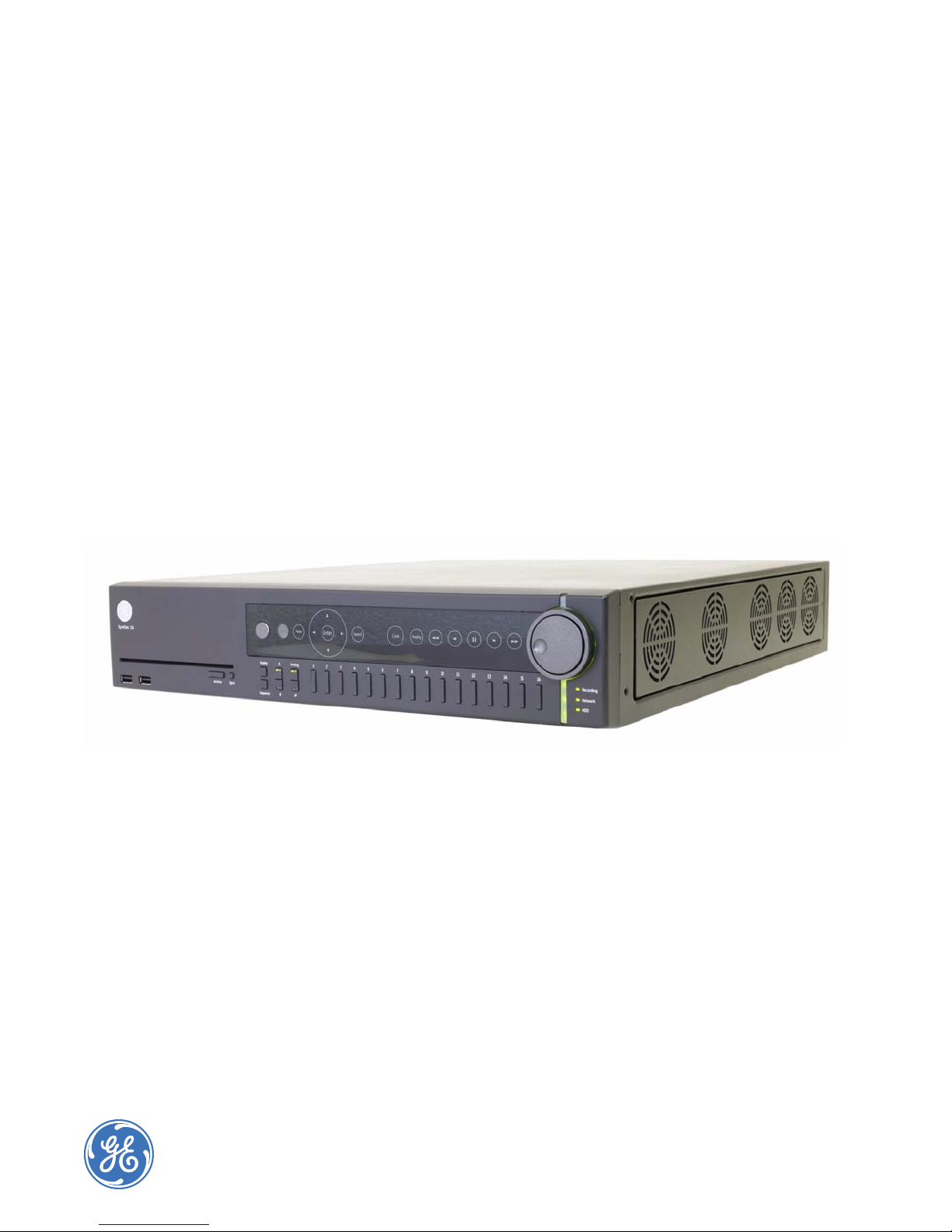
SymDec 16 plus 4
User Manual
Page 2

Copyright Copyright © 2008, GE Security, Inc. All rights reserved.
This document may not be copied in whole or in part or otherwise reproduced without prior
written consent from GE Security except where specifically permitted under US and
international copyright law.
Document number/Revision: 0150-0325C (January 2008).
,
Disclaimer The information in this document is subject to change without notice. GE Security
(“GE Security”) assumes no responsibility for inaccuracies or omissions and specifically
disclaims any liabilities, losses, or risks, personal or otherwise, incurred as a consequence,
directly or indirectly, of the use or application of any of the contents of this document. For the
latest documentation, contact your local supplier or visit us online at www.gesecurity.com.
This publication may contain examples of screen captures and reports used in daily operations.
Examples may include fictitious names of individuals and companies. Any similarity to names
and addresses of actual businesses or persons is entirely coincidental.
Trademarks and patents GE and the GE monogram are registered trademarks of General Electric Company.
The SymDec 16 plus 4 product and logo are registered trademarks of GE Security.
Other trade names used in this document may be trademarks or registered trademarks of the
manufacturers or vendors of the respective products.
Inc.
Software license agreement Important: This end-user license agreement (“Agreement”) is a legal agreement between
GE SECURITY and You. Read the following terms and conditions carefully before installing or
using this Software. This agreement provides a license from GE SECURITY to use the Software.
It also contains warranty information, disclaimers, and liability limitations. Installing and/or
using the Software confirms Your agreement to be bound by these terms and conditions. If You
do not agree with these terms and conditions, do not install or use the Software or, if already
installed, immediately cease all use of the Software and promptly uninstall all components of
the Software.
1. Definitions. The following definitions apply to this document:
a. “GE SECURITY”, with respect to title to or warranty of the Software, means GE Security
Inc., a Delaware corporation.
b. “Software” means SymNav, the executable software or firmware programs and accom-
panying documentation installed on the GE SECURITY products, plus any upgrades,
modified versions, updates, additions, and copies of the software furnished to Customer
during the term of the license granted herein.
c. “Documentation” means all associated media, printed materials, and electronic docu-
mentation accompanying the Software.
d. “Licensed Product” means the Software and Documentation.
e. “Customer” means the person or organization, or parent or subsidiary thereof, who uses
the Software for its intended purposes, and excludes distributors, authorized resellers,
value-added resellers and original equipment manufacturers. Customer may be
referred to as You or Your, whether an individual or a business entity of any kind.
f. “Machine” means the computer, workstation, terminal, or other hardware product on
which the Software is installed.
2. License. All rights to and in the Licensed Product, including, but not limited to, copyrights,
patents, trademarks, and trade secrets, belong to GE SECURITY, and GE SECURITY retains title
to each copy of the Software. You agree that GE SECURITY at any time, upon reasonable
notice, may audit Your use of the Software for compliance with the terms and conditions of
this Agreement. Subject to the terms and conditions of this Agreement, GE SECURITY grants
You a nonexclusive license to use the Software, but only in the country where acquired,
provided that You agree to the following:
You may:
a. install and use the Software on a single Machine at one time, unless You have purchased
additional copies of the Software, in which case You may install the software on the
number of Machines for which You have purchased copies of the Software;
b. use the original copy of the Software provided to You for backup purposes.
Page 3

You may not:
a. transfer or distribute the Licensed Product to others, in electronic format or otherwise, and this
Agreement shall automatically terminate in the event of such a transfer or distribution;
b. use the Software over a computer network;
c. sell, rent, lease, or sublicense the Software;
d. copy or modify the Licensed Product for any purpose, including for backup purposes.
3. Term. This Agreement is effective until terminated. You may terminate this Agreement by
uninstalling all components of the Software from all Machines and returning the Software to
GE SECURITY. GE SECURITY may terminate this Agreement if You breach any of these terms
and conditions. Upon termination of this Agreement for any reason, You agree to uninstall
all components of the Software and return the Licensed Product to GE SECURITY. All
provisions of this Agreement relating to (i) disclaimer of warranties; (ii) limitations on liability,
remedies, and damages; and (iii) GE SECURITY’s proprietary rights, shall survive termination
of this Agreement.
4. Object code. The Software is delivered in object code only. You may not alter, merge,
modify, adapt, or translate the Software, nor decompile, disassemble, reverse-engineer, or
otherwise reduce the Software to a human-perceivable form, nor create derivative works or
programs based on the Software.
5. Limited warranty. GE SECURITY warrants that for one (1) year from the date of delivery of
the Licensed Product (Software Warranty Period), the functions contained in the Software will
be fit for their intended purpose as described in the applicable Documentation from
GE SECURITY, and will conform in all material respects to the specifications stated in such
Documentation. GE SECURITY does not warrant that the operation of the Software will be
uninterrupted or error-free. GE SECURITY does warrant that the media on which the
Software is furnished will be free from defects in materials and workmanship under normal
use for a period of thirty (30) days from the date of delivery (Media Warranty Period). Except
as specifically provided therein, any other software and any hardware furnished with or
accompanying the Software is not warranted by GE SECURITY.
Your exclusive remedy under this limited warranty for nonconforming Software shall be
repair or replacement of the Software, at the sole discretion of GE SECURITY. To obtain a
repair or replacement of nonconforming Software, contact GE SECURITY Customer Service
toll-free at 888-GESECURity or online at www.gesecurity.com during the Software Warranty
Period.
Except as expressly provided above, the licensed product is provided “as is” without
warranty of any kind, either expressed or implied, including, but not limited to, implied
warranties of merchantability or fitness for a particular purpose and, except as expressly
provided above, You assume the entire risk as to the quality and performance of the licensed
product.
6. Limitation of liability. GE SECURITY’s sole obligation or liability under this agreement is the
repair or replacement of nonconforming software and/or defective media according to the
limited warranty above. In no event will GE SECURITY be liable for damages, whether
consequential, incidental, or indirect, nor for loss of data, loss of profits, or lost savings,
arising from use or inability to use the software or documentation (or any hardware
furnished with the software), even if GE SECURITY has been advised of the possibility of such
damages, nor for any claim by any third party.
7. General. Any materials provided to You by GE SECURITY shall not be exported or
reexported in violation of any export provisions of the USA or any other applicable
jurisdiction. Any attempt to sublicense, assign, or transfer any of the rights, duties, or
obligations hereunder shall be void. This Agreement shall be governed by and interpreted
under the laws of the State of New York, United States of America, without regard to conflicts
of law provisions. You hereby consent to the exclusive jurisdiction of the state and federal
courts located in Multnomah County, Oregon, to resolve any disputes arising under or in
connection with this Agreement, with venue in Portland, Oregon.
iii
Page 4
SymDec 16 plus 4
iv
User Manual
8. Restricted rights legend. The Licensed Product is provided with RESTRICTED RIGHTS. In
the event the United States Government or an agency thereof is granted a license, the
following additional terms apply: Restricted Computer Software, as defined in the
Commercial Computer Software–Restricted Rights clause at Federal Acquisition Regulations
52.227-19, and the restrictions as provided in subparagraphs (c)(1) and (c)(2) thereof; and as
applicable, the Government’s rights to use, modify, reproduce, release, perform, display, or
disclose the Software also are restricted as provided by paragraphs (b)(2) and (b)(3) of the
Rights in Noncommercial Technical Data and Computer Software–Small Business Innovative
Research (SBIR) Program clause at DFARS 252.227-7018.
9. Acknowledgment. You acknowledge that You have read and understand this agreement
and agree to be bound by its terms. You further agree that this agreement is the complete
and exclusive statement of the agreement between You and GE SECURITY, and supersedes
any proposal or prior agreement, oral or written, and any other communication relating to
the subject matter of this agreement.
Intended use Use this product only for the purpose it was designed for; refer to the data sheet and user
documentation. For the latest product information, contact your local supplier or visit us online
at www.gesecurity.com.
Non-LPS or TNV output connectors identify the type of circuit, intended cable type, or relevant
circuit characteristics. (Marking or Instruction)
FCC compliance This equipment has been tested and found to comply with the limits for a Class A digital device,
Regulatory
pursuant to part 15 of the FCC Rules. These limits are designed to provide reasonable
protection against harmful interference when the equipment is operated in a commercial
environment. This equipment generates, uses, and can radiate radio frequency energy and, if
not installed and used in accordance with the instruction manual, may cause harmful
interference to radio communications.
You are cautioned that any changes or modifications not expressly approved by the party
responsible for compliance could void the user’s authority to operate the equipment.
CATUION: Risk of Explosion if Battery is replaced by an Incorrect Type. Dispose of Used Batteries According
to the Instructions.
Page 5

Chapter 1. Introduction. . . . . . . . . . . . . . . . . . . . . . . . . . . . . . . . . . . . . . . . . . . . . . . . . . . . . . . . . . . . 1
Introduction . . . . . . . . . . . . . . . . . . . . . . . . . . . . . . . . . . . . . . . . . . . . . . . . . . . . . . . . . . . . . . . . . . . . . . . . . . . . . . . . . . . . 2
Conventions used in this document. . . . . . . . . . . . . . . . . . . . . . . . . . . . . . . . . . . . . . . . . . . . . . . . . . . . . . . . . . . . . . . . . . .2
Safety terms and symbols . . . . . . . . . . . . . . . . . . . . . . . . . . . . . . . . . . . . . . . . . . . . . . . . . . . . . . . . . . . . . . . . . . . . . . . . . . . .2
Product overview. . . . . . . . . . . . . . . . . . . . . . . . . . . . . . . . . . . . . . . . . . . . . . . . . . . . . . . . . . . . . . . . . . . . . . . . . . . . . . . . 3
Features. . . . . . . . . . . . . . . . . . . . . . . . . . . . . . . . . . . . . . . . . . . . . . . . . . . . . . . . . . . . . . . . . . . . . . . . . . . . . . . . . . . . . . . . . . . . .3
Product contents . . . . . . . . . . . . . . . . . . . . . . . . . . . . . . . . . . . . . . . . . . . . . . . . . . . . . . . . . . . . . . . . . . . . . . . . . . . . . . . . . . . .4
Installation Environment . . . . . . . . . . . . . . . . . . . . . . . . . . . . . . . . . . . . . . . . . . . . . . . . . . . . . . . . . . . . . . . . . . . . . . . . . . . . .4
Associated Equipment . . . . . . . . . . . . . . . . . . . . . . . . . . . . . . . . . . . . . . . . . . . . . . . . . . . . . . . . . . . . . . . . . . . . . . . . . . . . . . .5
Rack Mounting. . . . . . . . . . . . . . . . . . . . . . . . . . . . . . . . . . . . . . . . . . . . . . . . . . . . . . . . . . . . . . . . . . . . . . . . . . . . . . . . . . . . . . .6
Passwords. . . . . . . . . . . . . . . . . . . . . . . . . . . . . . . . . . . . . . . . . . . . . . . . . . . . . . . . . . . . . . . . . . . . . . . . . . . . . . . . . . . . . . . . . . .7
Default IP Addresses . . . . . . . . . . . . . . . . . . . . . . . . . . . . . . . . . . . . . . . . . . . . . . . . . . . . . . . . . . . . . . . . . . . . . . . . . . . . . . . . .7
Chapter 2. Connections and Controls . . . . . . . . . . . . . . . . . . . . . . . . . . . . . . . . . . . . . . . . . . . . . . . 9
Front Panel Controls and Features . . . . . . . . . . . . . . . . . . . . . . . . . . . . . . . . . . . . . . . . . . . . . . . . . . . . . . . . . . . . . . .10
Back Panel Connections. . . . . . . . . . . . . . . . . . . . . . . . . . . . . . . . . . . . . . . . . . . . . . . . . . . . . . . . . . . . . . . . . . . . . . . . .12
Camera Inputs. . . . . . . . . . . . . . . . . . . . . . . . . . . . . . . . . . . . . . . . . . . . . . . . . . . . . . . . . . . . . . . . . . . . . . . . . . . . . . . . . . . . . 12
Audio Inputs and Output . . . . . . . . . . . . . . . . . . . . . . . . . . . . . . . . . . . . . . . . . . . . . . . . . . . . . . . . . . . . . . . . . . . . . . . . . . . 13
Alarm Inputs. . . . . . . . . . . . . . . . . . . . . . . . . . . . . . . . . . . . . . . . . . . . . . . . . . . . . . . . . . . . . . . . . . . . . . . . . . . . . . . . . . . . . . . 13
USB connectors. . . . . . . . . . . . . . . . . . . . . . . . . . . . . . . . . . . . . . . . . . . . . . . . . . . . . . . . . . . . . . . . . . . . . . . . . . . . . . . . . . . . 13
Ethernet Port . . . . . . . . . . . . . . . . . . . . . . . . . . . . . . . . . . . . . . . . . . . . . . . . . . . . . . . . . . . . . . . . . . . . . . . . . . . . . . . . . . . . . . 14
RS-485/RS-422 I/O connectors . . . . . . . . . . . . . . . . . . . . . . . . . . . . . . . . . . . . . . . . . . . . . . . . . . . . . . . . . . . . . . . . . . . . . 14
RS232 Port . . . . . . . . . . . . . . . . . . . . . . . . . . . . . . . . . . . . . . . . . . . . . . . . . . . . . . . . . . . . . . . . . . . . . . . . . . . . . . . . . . . . . . . . 15
VGA connector. . . . . . . . . . . . . . . . . . . . . . . . . . . . . . . . . . . . . . . . . . . . . . . . . . . . . . . . . . . . . . . . . . . . . . . . . . . . . . . . . . . . . 15
DVI connector . . . . . . . . . . . . . . . . . . . . . . . . . . . . . . . . . . . . . . . . . . . . . . . . . . . . . . . . . . . . . . . . . . . . . . . . . . . . . . . . . . . . . 16
Monitor A/B composite output. . . . . . . . . . . . . . . . . . . . . . . . . . . . . . . . . . . . . . . . . . . . . . . . . . . . . . . . . . . . . . . . . . . . . . 16
Alarm out connector . . . . . . . . . . . . . . . . . . . . . . . . . . . . . . . . . . . . . . . . . . . . . . . . . . . . . . . . . . . . . . . . . . . . . . . . . . . . . . . 16
Power Connector . . . . . . . . . . . . . . . . . . . . . . . . . . . . . . . . . . . . . . . . . . . . . . . . . . . . . . . . . . . . . . . . . . . . . . . . . . . . . . . . . . 17
Connection Diagrams. . . . . . . . . . . . . . . . . . . . . . . . . . . . . . . . . . . . . . . . . . . . . . . . . . . . . . . . . . . . . . . . . . . . . . . . . . .18
The Remote Controller . . . . . . . . . . . . . . . . . . . . . . . . . . . . . . . . . . . . . . . . . . . . . . . . . . . . . . . . . . . . . . . . . . . . . . . . . .20
v
Page 6

SymDec 16 plus 4
vi
User Manual
Chapter 3. Basic Operations . . . . . . . . . . . . . . . . . . . . . . . . . . . . . . . . . . . . . . . . . . . . . . . . . . . . . . 21
Front Panel Controls. . . . . . . . . . . . . . . . . . . . . . . . . . . . . . . . . . . . . . . . . . . . . . . . . . . . . . . . . . . . . . . . . . . . . . . . . . . . 22
Operations . . . . . . . . . . . . . . . . . . . . . . . . . . . . . . . . . . . . . . . . . . . . . . . . . . . . . . . . . . . . . . . . . . . . . . . . . . . . . . . . . . . . 24
How to Log In . . . . . . . . . . . . . . . . . . . . . . . . . . . . . . . . . . . . . . . . . . . . . . . . . . . . . . . . . . . . . . . . . . . . . . . . . . . . . . . . . . . . . . 24
How to change the display for Monitor A and Monitor B . . . . . . . . . . . . . . . . . . . . . . . . . . . . . . . . . . . . . . . . . . . . . . 24
How to change the display to a full-screen analog view . . . . . . . . . . . . . . . . . . . . . . . . . . . . . . . . . . . . . . . . . . . . . . 24
How to change the display to a full-screen IP view . . . . . . . . . . . . . . . . . . . . . . . . . . . . . . . . . . . . . . . . . . . . . . . . . . . 24
How to view multiscreen displays . . . . . . . . . . . . . . . . . . . . . . . . . . . . . . . . . . . . . . . . . . . . . . . . . . . . . . . . . . . . . . . . . . . 24
How to change the display presets. . . . . . . . . . . . . . . . . . . . . . . . . . . . . . . . . . . . . . . . . . . . . . . . . . . . . . . . . . . . . . . . . . 25
How to enter Cameo mode . . . . . . . . . . . . . . . . . . . . . . . . . . . . . . . . . . . . . . . . . . . . . . . . . . . . . . . . . . . . . . . . . . . . . . . . . 25
How to display Sequencing . . . . . . . . . . . . . . . . . . . . . . . . . . . . . . . . . . . . . . . . . . . . . . . . . . . . . . . . . . . . . . . . . . . . . . . . . 25
How to return to the default sequence list . . . . . . . . . . . . . . . . . . . . . . . . . . . . . . . . . . . . . . . . . . . . . . . . . . . . . . . . . . . 25
How to enter Playback mode . . . . . . . . . . . . . . . . . . . . . . . . . . . . . . . . . . . . . . . . . . . . . . . . . . . . . . . . . . . . . . . . . . . . . . . 25
How to Search using Disk Analysis . . . . . . . . . . . . . . . . . . . . . . . . . . . . . . . . . . . . . . . . . . . . . . . . . . . . . . . . . . . . . . . . . . 26
How to Search using the Filters Screen . . . . . . . . . . . . . . . . . . . . . . . . . . . . . . . . . . . . . . . . . . . . . . . . . . . . . . . . . . . . . . 26
How to archive from the Search screen . . . . . . . . . . . . . . . . . . . . . . . . . . . . . . . . . . . . . . . . . . . . . . . . . . . . . . . . . . . . . 26
How to use the Archive screen . . . . . . . . . . . . . . . . . . . . . . . . . . . . . . . . . . . . . . . . . . . . . . . . . . . . . . . . . . . . . . . . . . . . . . 27
How to setup and stream an IP camera to a SymDec 16 . . . . . . . . . . . . . . . . . . . . . . . . . . . . . . . . . . . . . . . . . . . . . 27
How to setup a KTD-405 keypad to work with the SymDec 16 . . . . . . . . . . . . . . . . . . . . . . . . . . . . . . . . . . . . . . . . 28
How to set the IP camera option to a keypad button . . . . . . . . . . . . . . . . . . . . . . . . . . . . . . . . . . . . . . . . . . . . . . . . . 28
KTD-405 keypad mapping to SymDec 16 front panel. . . . . . . . . . . . . . . . . . . . . . . . . . . . . . . . . . . . . . . . . . . . . . . . . 29
Page 7

Chapter 4. Programming the SymDec 16 plus 4 . . . . . . . . . . . . . . . . . . . . . . . . . . . . . . . . . . . . . 31
Log In . . . . . . . . . . . . . . . . . . . . . . . . . . . . . . . . . . . . . . . . . . . . . . . . . . . . . . . . . . . . . . . . . . . . . . . . . . . . . . . . . . . . . . . . .32
Main Menu . . . . . . . . . . . . . . . . . . . . . . . . . . . . . . . . . . . . . . . . . . . . . . . . . . . . . . . . . . . . . . . . . . . . . . . . . . . . . . . . . . . . . . . . 33
Cameras menu . . . . . . . . . . . . . . . . . . . . . . . . . . . . . . . . . . . . . . . . . . . . . . . . . . . . . . . . . . . . . . . . . . . . . . . . . . . . . . . . .35
Analog Camera menu. . . . . . . . . . . . . . . . . . . . . . . . . . . . . . . . . . . . . . . . . . . . . . . . . . . . . . . . . . . . . . . . . . . . . . . . . . . . . . 35
IP Camera menu . . . . . . . . . . . . . . . . . . . . . . . . . . . . . . . . . . . . . . . . . . . . . . . . . . . . . . . . . . . . . . . . . . . . . . . . . . . . . . . . . . . 42
The Schedule menu . . . . . . . . . . . . . . . . . . . . . . . . . . . . . . . . . . . . . . . . . . . . . . . . . . . . . . . . . . . . . . . . . . . . . . . . . . . . .47
New Schedule . . . . . . . . . . . . . . . . . . . . . . . . . . . . . . . . . . . . . . . . . . . . . . . . . . . . . . . . . . . . . . . . . . . . . . . . . . . . . . . . . . . . . 48
Macros . . . . . . . . . . . . . . . . . . . . . . . . . . . . . . . . . . . . . . . . . . . . . . . . . . . . . . . . . . . . . . . . . . . . . . . . . . . . . . . . . . . . . . . . . . . . 49
Create new Macro . . . . . . . . . . . . . . . . . . . . . . . . . . . . . . . . . . . . . . . . . . . . . . . . . . . . . . . . . . . . . . . . . . . . . . . . . . . . . . . . . 50
Edit Macro . . . . . . . . . . . . . . . . . . . . . . . . . . . . . . . . . . . . . . . . . . . . . . . . . . . . . . . . . . . . . . . . . . . . . . . . . . . . . . . . . . . . . . . . . 51
Front Panel . . . . . . . . . . . . . . . . . . . . . . . . . . . . . . . . . . . . . . . . . . . . . . . . . . . . . . . . . . . . . . . . . . . . . . . . . . . . . . . . . . . . . . . . 52
How to schedule a macro . . . . . . . . . . . . . . . . . . . . . . . . . . . . . . . . . . . . . . . . . . . . . . . . . . . . . . . . . . . . . . . . . . . . . . . . . . 52
The Alarms menu . . . . . . . . . . . . . . . . . . . . . . . . . . . . . . . . . . . . . . . . . . . . . . . . . . . . . . . . . . . . . . . . . . . . . . . . . . . . . . . . . . 54
Notification . . . . . . . . . . . . . . . . . . . . . . . . . . . . . . . . . . . . . . . . . . . . . . . . . . . . . . . . . . . . . . . . . . . . . . . . . . . . . . . . . . . . . . . . 54
Silent Alarm. . . . . . . . . . . . . . . . . . . . . . . . . . . . . . . . . . . . . . . . . . . . . . . . . . . . . . . . . . . . . . . . . . . . . . . . . . . . . . . . . . . . . . . . 55
Alarm Inputs and Outputs . . . . . . . . . . . . . . . . . . . . . . . . . . . . . . . . . . . . . . . . . . . . . . . . . . . . . . . . . . . . . . . . . . . . . . . . . . 55
The Users menu . . . . . . . . . . . . . . . . . . . . . . . . . . . . . . . . . . . . . . . . . . . . . . . . . . . . . . . . . . . . . . . . . . . . . . . . . . . . . . . . 57
Add New User . . . . . . . . . . . . . . . . . . . . . . . . . . . . . . . . . . . . . . . . . . . . . . . . . . . . . . . . . . . . . . . . . . . . . . . . . . . . . . . . . . . . . 57
Edit Users. . . . . . . . . . . . . . . . . . . . . . . . . . . . . . . . . . . . . . . . . . . . . . . . . . . . . . . . . . . . . . . . . . . . . . . . . . . . . . . . . . . . . . . . . . 58
The Network menu . . . . . . . . . . . . . . . . . . . . . . . . . . . . . . . . . . . . . . . . . . . . . . . . . . . . . . . . . . . . . . . . . . . . . . . . . . . . .59
IP Settings . . . . . . . . . . . . . . . . . . . . . . . . . . . . . . . . . . . . . . . . . . . . . . . . . . . . . . . . . . . . . . . . . . . . . . . . . . . . . . . . . . . . . . . . . 60
IP Advanced . . . . . . . . . . . . . . . . . . . . . . . . . . . . . . . . . . . . . . . . . . . . . . . . . . . . . . . . . . . . . . . . . . . . . . . . . . . . . . . . . . . . . . . 61
Muticast Video Streaming Overview . . . . . . . . . . . . . . . . . . . . . . . . . . . . . . . . . . . . . . . . . . . . . . . . . . . . . . . . . . . . . . . . 62
Services . . . . . . . . . . . . . . . . . . . . . . . . . . . . . . . . . . . . . . . . . . . . . . . . . . . . . . . . . . . . . . . . . . . . . . . . . . . . . . . . . . . . . . . . . . . 63
Streaming . . . . . . . . . . . . . . . . . . . . . . . . . . . . . . . . . . . . . . . . . . . . . . . . . . . . . . . . . . . . . . . . . . . . . . . . . . . . . . . . . . . . . . . . . 64
Serial Passthrough . . . . . . . . . . . . . . . . . . . . . . . . . . . . . . . . . . . . . . . . . . . . . . . . . . . . . . . . . . . . . . . . . . . . . . . . . . . . . . . . . 65
Email/TCP Notification. . . . . . . . . . . . . . . . . . . . . . . . . . . . . . . . . . . . . . . . . . . . . . . . . . . . . . . . . . . . . . . . . . . . . . . . . . . . . . 66
Email Setup. . . . . . . . . . . . . . . . . . . . . . . . . . . . . . . . . . . . . . . . . . . . . . . . . . . . . . . . . . . . . . . . . . . . . . . . . . . . . . . . . . . . . . . . 67
Notification Setup. . . . . . . . . . . . . . . . . . . . . . . . . . . . . . . . . . . . . . . . . . . . . . . . . . . . . . . . . . . . . . . . . . . . . . . . . . . . . . . . . . 68
The Display menu . . . . . . . . . . . . . . . . . . . . . . . . . . . . . . . . . . . . . . . . . . . . . . . . . . . . . . . . . . . . . . . . . . . . . . . . . . . . . .69
The System menu . . . . . . . . . . . . . . . . . . . . . . . . . . . . . . . . . . . . . . . . . . . . . . . . . . . . . . . . . . . . . . . . . . . . . . . . . . . . . . 70
Front Panel . . . . . . . . . . . . . . . . . . . . . . . . . . . . . . . . . . . . . . . . . . . . . . . . . . . . . . . . . . . . . . . . . . . . . . . . . . . . . . . . . . . . . . . . 70
Audio Output . . . . . . . . . . . . . . . . . . . . . . . . . . . . . . . . . . . . . . . . . . . . . . . . . . . . . . . . . . . . . . . . . . . . . . . . . . . . . . . . . . . . . . 71
Time/Date . . . . . . . . . . . . . . . . . . . . . . . . . . . . . . . . . . . . . . . . . . . . . . . . . . . . . . . . . . . . . . . . . . . . . . . . . . . . . . . . . . . . . . . . . 72
Security . . . . . . . . . . . . . . . . . . . . . . . . . . . . . . . . . . . . . . . . . . . . . . . . . . . . . . . . . . . . . . . . . . . . . . . . . . . . . . . . . . . . . . . . . . . 74
Languages . . . . . . . . . . . . . . . . . . . . . . . . . . . . . . . . . . . . . . . . . . . . . . . . . . . . . . . . . . . . . . . . . . . . . . . . . . . . . . . . . . . . . . . . 75
Disk Tools. . . . . . . . . . . . . . . . . . . . . . . . . . . . . . . . . . . . . . . . . . . . . . . . . . . . . . . . . . . . . . . . . . . . . . . . . . . . . . . . . . . . . . . . . . 76
Serial Communications. . . . . . . . . . . . . . . . . . . . . . . . . . . . . . . . . . . . . . . . . . . . . . . . . . . . . . . . . . . . . . . . . . . . . . . . . . . . . 78
Firmware Upgrade . . . . . . . . . . . . . . . . . . . . . . . . . . . . . . . . . . . . . . . . . . . . . . . . . . . . . . . . . . . . . . . . . . . . . . . . . . . . . . . . . 80
Setting Tool. . . . . . . . . . . . . . . . . . . . . . . . . . . . . . . . . . . . . . . . . . . . . . . . . . . . . . . . . . . . . . . . . . . . . . . . . . . . . . . . . . . . . . . . 81
Shutdown . . . . . . . . . . . . . . . . . . . . . . . . . . . . . . . . . . . . . . . . . . . . . . . . . . . . . . . . . . . . . . . . . . . . . . . . . . . . . . . . . . . . . . . . . 82
The Info menu. . . . . . . . . . . . . . . . . . . . . . . . . . . . . . . . . . . . . . . . . . . . . . . . . . . . . . . . . . . . . . . . . . . . . . . . . . . . . . . . . .83
Health. . . . . . . . . . . . . . . . . . . . . . . . . . . . . . . . . . . . . . . . . . . . . . . . . . . . . . . . . . . . . . . . . . . . . . . . . . . . . . . . . . . . . . . . . . . . . 83
System . . . . . . . . . . . . . . . . . . . . . . . . . . . . . . . . . . . . . . . . . . . . . . . . . . . . . . . . . . . . . . . . . . . . . . . . . . . . . . . . . . . . . . . . . . . . 84
vii
Page 8

SymDec 16 plus 4
viii
User Manual
Network . . . . . . . . . . . . . . . . . . . . . . . . . . . . . . . . . . . . . . . . . . . . . . . . . . . . . . . . . . . . . . . . . . . . . . . . . . . . . . . . . . . . . . . . . . . 85
Log . . . . . . . . . . . . . . . . . . . . . . . . . . . . . . . . . . . . . . . . . . . . . . . . . . . . . . . . . . . . . . . . . . . . . . . . . . . . . . . . . . . . . . . . . . . . . . . . 86
Chapter 5. SymNav and SymBrowser . . . . . . . . . . . . . . . . . . . . . . . . . . . . . . . . . . . . . . . . . . . . . . 87
SymNav . . . . . . . . . . . . . . . . . . . . . . . . . . . . . . . . . . . . . . . . . . . . . . . . . . . . . . . . . . . . . . . . . . . . . . . . . . . . . . . . . . . . . . . 88
Minimum System Requirements. . . . . . . . . . . . . . . . . . . . . . . . . . . . . . . . . . . . . . . . . . . . . . . . . . . . . . . . . . . . . . . . . . . . . 88
Installing SymNav software from CD-ROM. . . . . . . . . . . . . . . . . . . . . . . . . . . . . . . . . . . . . . . . . . . . . . . . . . . . . . . . . . . 88
Starting SymNav software . . . . . . . . . . . . . . . . . . . . . . . . . . . . . . . . . . . . . . . . . . . . . . . . . . . . . . . . . . . . . . . . . . . . . . . . . .88
The SymBrowser Webserver. . . . . . . . . . . . . . . . . . . . . . . . . . . . . . . . . . . . . . . . . . . . . . . . . . . . . . . . . . . . . . . . . . . . . 90
Search. . . . . . . . . . . . . . . . . . . . . . . . . . . . . . . . . . . . . . . . . . . . . . . . . . . . . . . . . . . . . . . . . . . . . . . . . . . . . . . . . . . . . . . . . . . . . 91
User . . . . . . . . . . . . . . . . . . . . . . . . . . . . . . . . . . . . . . . . . . . . . . . . . . . . . . . . . . . . . . . . . . . . . . . . . . . . . . . . . . . . . . . . . . . . . . . 92
Configure options . . . . . . . . . . . . . . . . . . . . . . . . . . . . . . . . . . . . . . . . . . . . . . . . . . . . . . . . . . . . . . . . . . . . . . . . . . . . . . . . . . 93
Cameras. . . . . . . . . . . . . . . . . . . . . . . . . . . . . . . . . . . . . . . . . . . . . . . . . . . . . . . . . . . . . . . . . . . . . . . . . . . . . . . . . . . . . . . . . . . 94
Schedule. . . . . . . . . . . . . . . . . . . . . . . . . . . . . . . . . . . . . . . . . . . . . . . . . . . . . . . . . . . . . . . . . . . . . . . . . . . . . . . . . . . . . . . . . .102
Alarms. . . . . . . . . . . . . . . . . . . . . . . . . . . . . . . . . . . . . . . . . . . . . . . . . . . . . . . . . . . . . . . . . . . . . . . . . . . . . . . . . . . . . . . . . . . .104
Network . . . . . . . . . . . . . . . . . . . . . . . . . . . . . . . . . . . . . . . . . . . . . . . . . . . . . . . . . . . . . . . . . . . . . . . . . . . . . . . . . . . . . . . . . .106
System . . . . . . . . . . . . . . . . . . . . . . . . . . . . . . . . . . . . . . . . . . . . . . . . . . . . . . . . . . . . . . . . . . . . . . . . . . . . . . . . . . . . . . . . . . .114
Info . . . . . . . . . . . . . . . . . . . . . . . . . . . . . . . . . . . . . . . . . . . . . . . . . . . . . . . . . . . . . . . . . . . . . . . . . . . . . . . . . . . . . . . . . . . . . . .121
Symbrowser . . . . . . . . . . . . . . . . . . . . . . . . . . . . . . . . . . . . . . . . . . . . . . . . . . . . . . . . . . . . . . . . . . . . . . . . . . . . . . . . . . . . . .123
Chapter 6. Searching and Archiving. . . . . . . . . . . . . . . . . . . . . . . . . . . . . . . . . . . . . . . . . . . . . . . 125
Searching . . . . . . . . . . . . . . . . . . . . . . . . . . . . . . . . . . . . . . . . . . . . . . . . . . . . . . . . . . . . . . . . . . . . . . . . . . . . . . . . . . . . 126
The Disk Analysis Screen. . . . . . . . . . . . . . . . . . . . . . . . . . . . . . . . . . . . . . . . . . . . . . . . . . . . . . . . . . . . . . . . . . . . . . . . . . .126
Search Filters . . . . . . . . . . . . . . . . . . . . . . . . . . . . . . . . . . . . . . . . . . . . . . . . . . . . . . . . . . . . . . . . . . . . . . . . . . . . . . . . . . . . .127
Date and Time Search . . . . . . . . . . . . . . . . . . . . . . . . . . . . . . . . . . . . . . . . . . . . . . . . . . . . . . . . . . . . . . . . . . . . . . . . . . . . .127
Camera Motion Search . . . . . . . . . . . . . . . . . . . . . . . . . . . . . . . . . . . . . . . . . . . . . . . . . . . . . . . . . . . . . . . . . . . . . . . . . . . .128
Daily Hours Search . . . . . . . . . . . . . . . . . . . . . . . . . . . . . . . . . . . . . . . . . . . . . . . . . . . . . . . . . . . . . . . . . . . . . . . . . . . . . . . .128
Search For Search. . . . . . . . . . . . . . . . . . . . . . . . . . . . . . . . . . . . . . . . . . . . . . . . . . . . . . . . . . . . . . . . . . . . . . . . . . . . . . . . .129
Search Results . . . . . . . . . . . . . . . . . . . . . . . . . . . . . . . . . . . . . . . . . . . . . . . . . . . . . . . . . . . . . . . . . . . . . . . . . . . . . . . . . . . .130
Archiving . . . . . . . . . . . . . . . . . . . . . . . . . . . . . . . . . . . . . . . . . . . . . . . . . . . . . . . . . . . . . . . . . . . . . . . . . . . . . . . . . . . . .131
Fullscreen Search Results Preview. . . . . . . . . . . . . . . . . . . . . . . . . . . . . . . . . . . . . . . . . . . . . . . . . . . . . . . . . . . . . . . . . .132
SymPlayer . . . . . . . . . . . . . . . . . . . . . . . . . . . . . . . . . . . . . . . . . . . . . . . . . . . . . . . . . . . . . . . . . . . . . . . . . . . . . . . . . . . . . . . .133
Chapter 7. Technical Specifications . . . . . . . . . . . . . . . . . . . . . . . . . . . . . . . . . . . . . . . . . . . . . . . 135
Technical Specifications . . . . . . . . . . . . . . . . . . . . . . . . . . . . . . . . . . . . . . . . . . . . . . . . . . . . . . . . . . . . . . . . . . . . . . . 136
General . . . . . . . . . . . . . . . . . . . . . . . . . . . . . . . . . . . . . . . . . . . . . . . . . . . . . . . . . . . . . . . . . . . . . . . . . . . . . . . . . . . . . . . . . . .136
Connections . . . . . . . . . . . . . . . . . . . . . . . . . . . . . . . . . . . . . . . . . . . . . . . . . . . . . . . . . . . . . . . . . . . . . . . . . . . . . . . . . . . . . .136
Video . . . . . . . . . . . . . . . . . . . . . . . . . . . . . . . . . . . . . . . . . . . . . . . . . . . . . . . . . . . . . . . . . . . . . . . . . . . . . . . . . . . . . . . . . . . . .136
Audio . . . . . . . . . . . . . . . . . . . . . . . . . . . . . . . . . . . . . . . . . . . . . . . . . . . . . . . . . . . . . . . . . . . . . . . . . . . . . . . . . . . . . . . . . . . . .137
On-screen Video Indicators . . . . . . . . . . . . . . . . . . . . . . . . . . . . . . . . . . . . . . . . . . . . . . . . . . . . . . . . . . . . . . . . . . . . . . . .137
Part Numbers . . . . . . . . . . . . . . . . . . . . . . . . . . . . . . . . . . . . . . . . . . . . . . . . . . . . . . . . . . . . . . . . . . . . . . . . . . . . . . . . . . . . .137
Factory Defaults . . . . . . . . . . . . . . . . . . . . . . . . . . . . . . . . . . . . . . . . . . . . . . . . . . . . . . . . . . . . . . . . . . . . . . . . . . . . . . 138
Menu defaults. . . . . . . . . . . . . . . . . . . . . . . . . . . . . . . . . . . . . . . . . . . . . . . . . . . . . . . . . . . . . . . . . . . . . . . . . . . . . . . . . . . . .138
IP addresses . . . . . . . . . . . . . . . . . . . . . . . . . . . . . . . . . . . . . . . . . . . . . . . . . . . . . . . . . . . . . . . . . . . . . . . . . . . . . . . . . . . . . .138
Streaming defaults . . . . . . . . . . . . . . . . . . . . . . . . . . . . . . . . . . . . . . . . . . . . . . . . . . . . . . . . . . . . . . . . . . . . . . . . . . . . . . . .139
Page 9

Chapter 8. Maintenance, support . . . . . . . . . . . . . . . . . . . . . . . . . . . . . . . . . . . . . . . . . . . . . . . . .141
Contacting technical support . . . . . . . . . . . . . . . . . . . . . . . . . . . . . . . . . . . . . . . . . . . . . . . . . . . . . . . . . . . . . . . . . . .142
Online publication library. . . . . . . . . . . . . . . . . . . . . . . . . . . . . . . . . . . . . . . . . . . . . . . . . . . . . . . . . . . . . . . . . . . . . . . . . . 142
ix
Page 10

SymDec 16 plus 4
x
User Manual
Page 11

Chapter 1 Introduction
This chapter provides an overview of your SymDec 16 plus 4, including the box
contents, the installation environment requirements and associated equipment you
right require before you begin installing, configuring, and using your SymDec 16
plus 4.
In this chapter:
Introduction. . . . . . . . . . . . . . . . . . . . . . . . . . . . . . . . . . . . . . . . . . . . . . . . 2
Conventions used in this document . . . . . . . . . . . . . . . . . . . . . . . . . . 2
Safety terms and symbols . . . . . . . . . . . . . . . . . . . . . . . . . . . . . . . . . . 2
Product overview . . . . . . . . . . . . . . . . . . . . . . . . . . . . . . . . . . . . . . . . . . . 3
Features . . . . . . . . . . . . . . . . . . . . . . . . . . . . . . . . . . . . . . . . . . . . . . . 3
Product contents. . . . . . . . . . . . . . . . . . . . . . . . . . . . . . . . . . . . . . . . . 4
Installation Environment . . . . . . . . . . . . . . . . . . . . . . . . . . . . . . . . . . 4
Associated Equipment . . . . . . . . . . . . . . . . . . . . . . . . . . . . . . . . . . . . 5
Rack Mounting . . . . . . . . . . . . . . . . . . . . . . . . . . . . . . . . . . . . . . . . . . 6
Passwords. . . . . . . . . . . . . . . . . . . . . . . . . . . . . . . . . . . . . . . . . . . . . . 7
Default IP Addresses . . . . . . . . . . . . . . . . . . . . . . . . . . . . . . . . . . . . . 7
Page 12

SymDec 16 plus 4
2
User Manual
Introduction
This is the GE SymDec 16 plus 4 User Manual for models:
• SymDec16 plus 4-320
• SymDec16 plus 4-640
• SymDec16 plus 4-1.28T
• SymDec16 plus 4-2T
• SymDec16 plus 4-3T
This document includes an overview of the product and detailed instructions explaining how to install and
configure the SymDec 16 plus 4.
There is also information describing how to contact technical support if you have questions or concerns.
To use this document effectively, you should have the following minimum qualifications:
• a basic knowledge of CCTV systems and components; and
• a basic knowledge of electrical wiring and low-voltage electrical connections.
Read these instructions and all ancillary documentation entirely before
installing or operating this product.
The most current versions of this and related documentation may be found on our website. Refer to Online
publication library on page 142 for instructions on accessing our online publication library.
Note: A qualified service person, complying with all applicable codes, should perform all required hardware installation.
Conventions used in this document
The following conventions are used in this document:
Bold Menu items and buttons.
Italic Emphasis of an instruction or point; special terms.
File names, path names, windows, panes, tabs, fields, variables, and other GUI elements.
Titles of books and various documents.
Monospace Text that displays on the computer screen.
Programming or coding sequences.
Blue italic Hyperlinks to cross-references, related topics, and URL addresses.
Safety terms and symbols
These terms may appear in this manual:
CAUTION
WARNING
Cautions identify conditions or practices that may result in damage to the equipment or other property.
Warnings identify conditions or practices that could result in equipment damage or serious personal injury.
Page 13

Chapter 1
Introduction
Product overview
The SymDec 16 plus 4 is a 16-channel Digital Video Recorder that uses “hybrid” recording that works with
both conventional analog cameras (16) and the new family of GE IP products. This uniq ue platform provides a
graceful migration path to digital recording – the future of video recording.
The SymDec 16 plus 4 allows users to record full-size images at full speed on every channel. Using MPEG-4
compression, the SymDec 16 plus 4 records at 30, 15, 10, 5, and 2 frames per second (NTSC) and has virtual
triplex functionality for simultaneous viewing, playback, and recording of video.
Note: In PAL video mode the SymDec 16 plus 4 can record at 25, 12.5, 8.3, 5, and 2.1 fps.
The SymDec 16 plus 4 has a form factor that’s one rack unit wide by 2U high, so it fits easily into a standard
19-inch rack. All models of the SymDec 16 plus 4 are equipped with a built-in DVD recorder, which allows for
portable storage or evidence transfer. In addition, the SymDec 16 plus 4 can be easily networked and recorded
video viewed remotely over Ethernet.
Features
• View live and recorded video from multiple SymDec 16 plus 4’s using SymNav software
• Advanced MPEG4 video compression
• 16-channel composite video input/output connection
• 9 video quality settings
• Triplex functionality
• Auto-detect video mode (NTSC or PAL) on startup
• VGA, DVI, and composite video outputs
• Records up to 30 frames per second (NTSC) of real time video
• Records up to 25 frames per second (PAL) of real time video
• Multi-level password protection
• Continuous recording in disk overwrite mode
• A simple on-screen display (OSD) menu system
• Remote configuration over TCP/IP
• Clock synchronization with network server
• Timed recording
• Dynamic IP addressing (DHCP)
• Support for Dynamic Domain Name Server (DDNS)
• Local search on time, date, and hardwired alarms
• Alarm handling with history log
• Unique at-a-glance alarm indicators
• Alarm notification through email
• Motion detection support
• Programmable Auto Delete Mode (ADM)
• Hard disk monitoring features
• Video streaming with UDP (User Datagram Protocol) and TCP (Transmission Control Protocol)
support
3
Page 14
SymDec 16 plus 4
4
User Manual
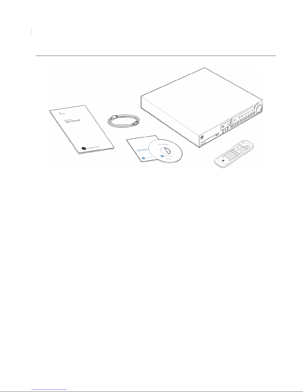
Figure 1. SymDec 16 plus 4 contents unboxed
Product contents
The SymDec 16 plus 4 system consists of the following:
• The SymDec 16 plus 4 unit
• 1 power cord (US)
• SymDec 16 plus 4 user manual
• SymNav software CD
• 6 terminating connectors (attached to back panel)
• IR remote controller
Inspect the package and contents for visible damage. If any components are damaged or missing, do not use
the unit; contact the supplier immediately. If you need to return the unit, you must ship it in the original box.
Installation Environment
Power: Ensure that the site's AC power is stable and within the rated voltage of the external power
supply. If the site's AC power is likely to have spikes or power dips, use power line conditioning
or an Uninterruptable Power Supply (UPS).
Ventilation: Install the unit in a well-ventilated area. Take note of the locations of the cooling vents
in the unit's enclosure, and ensure that they are not obstructed.
Temperature: Observe the unit's ambient temperatu re specifications when choosing a location space.
Extremes of heat or cold beyond the specified operating temperature limits may cause the unit to
fail. Do not install the unit on top of other hot equipment.
Moisture: Do not expose the unit to rain or moisture. Moisture can damage the internal components.
Do not install this unit near sources of water.
Page 15

Hard drives: Hard drives can be damaged if not handled properly. Do not set heavy objects on top of
this unit. Take all necessary precautions to protect this unit from transient voltages and do not
place this unit near magnetic devices. Do not move this unit while in operation. Wait at least 30
seconds after removing power before moving the unit or removing the hard drive.
Associated Equipment
Associated equipment you might need:
• Analog cameras (16).
• SymVeo IP Cameras (4).
• Analog or DVI monitor to view VGA video.
• Alarm input devices: Pressure sensors, motion detectors, etc.
• Alarm output devices: Buzzers, Sirens, Flashing Lights, etc.
• A PC connected by Ethernet.
• Microphones (4) with amplification.
• Speakers to hear audio.
• Symnet encoder/decoder to receive or send video.
Chapter 1
Introduction
5
For instructions regarding the connection of the associated security equipment in your system, please consult
the instruction manual of the associated equipment.
Page 16
SymDec 16 plus 4
6
User Manual
Rack Mounting
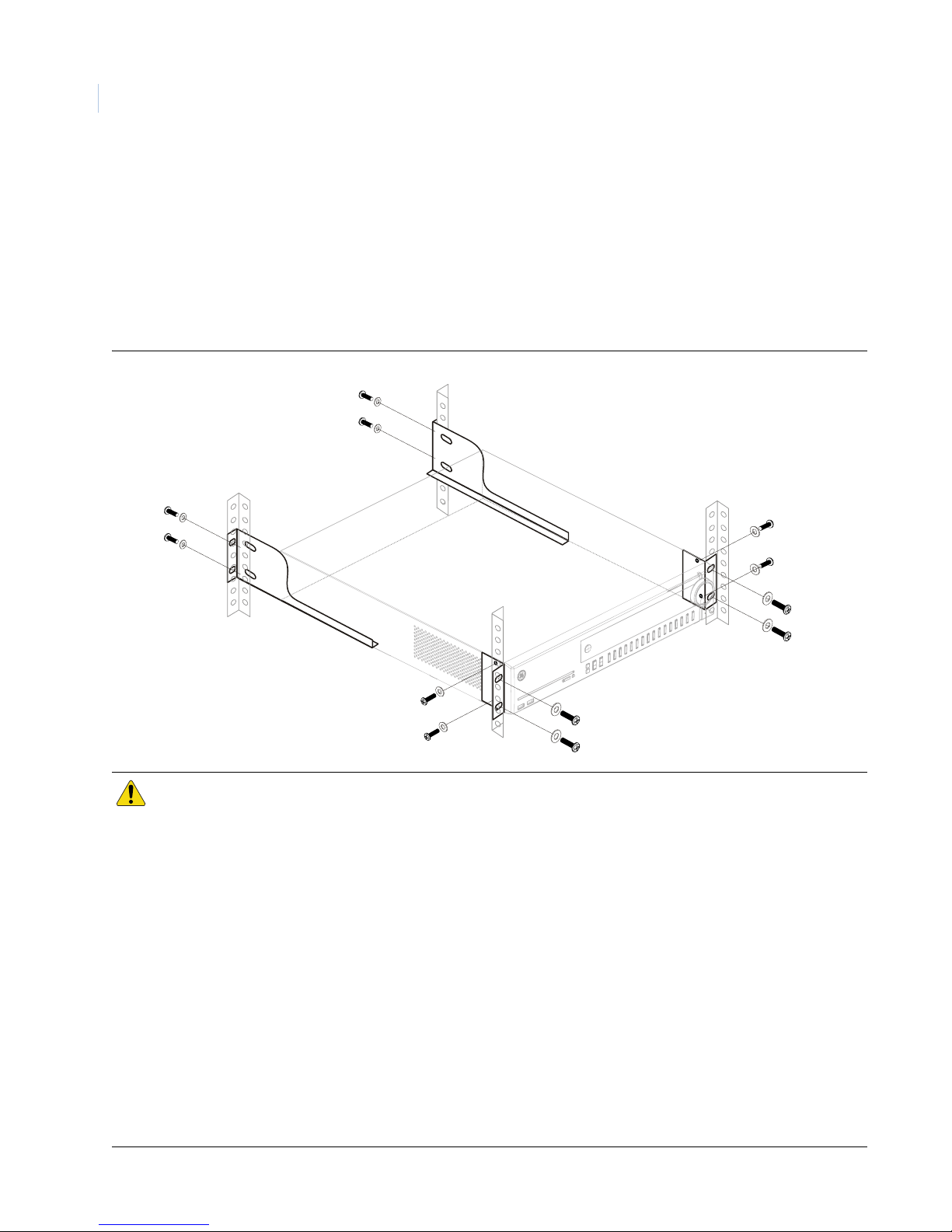
The SymDec 16 plus 4 is easily rack-mountable with the purchase of the model number SymDec16 plus 4-RK
rack mount kit. To install, do the following:
1. Attach the 2 small rack ears as shown with the supplied 10-32 x 1/2” screws.
2. Attach the 2 large rear support brackets to the rear rails with 10-32 x 3/4” screws.
1. Attach the SymSafe to the front rails with 10-32 x 3/4” screws.
Figure 2. Rack mount installation
CAUTION
Do not rackmount the SymDec16 plus 4 without the rear rails installed. Failure to install the rear rails can
damage the SymDec 16 plus 4.
Elevated Operating Ambient - If installed in a closed or multi-unit rack assembly, the operating ambient
temperature of the rack environment may be greater than room ambient. Therefore, consideration should
be given to installing the equipment in an environment compatible with the maximum ambient temperature
(40?) specified by the manufacturer.
Reduced Air Flow - Installation of the equipment in a rack should be such that the amount of air flow
required for safe operation of the equipment is not compromised.
Mechanical Loading - Mounting of the equipment in the rack should be such that a hazardous condition is
not achieved due to uneven mechanical loading.
Circuit Overloading - Consideration should be given to the connection of the equipment to the supply
circuit and the effect that overloading of the circuits might have on overcurrent protection and supply
wiring. Appropriate consideration of equipment nameplate ratings should be used when addressing this
concern.
Reliable Earthing - Reliable earthing of rack-mounted equipment should be maintained. Particular
attention should be given to supply connections other than direct connections to the branch circuit (e.g. use
of power strips).
Page 17
Chapter 1
Introduction
Passwords
Passwords are provided to limit access to the SymDec 16 plus 4, WebServer, and the SymNav software. It is
recommended that the default passwords be changed after installation is complete. As a security measure,
store the passwords in the administrator's secured files or in a limited access area.
Table 1. Default passwords
Password name Program Changeable by user Default password
user 1 On Screen Display (OSD) Yes, through the Main menu 111111
user 2 On Screen Display (OSD) Yes, through the Main menu 222222
user 3 On Screen Display (OSD) Yes, through the Main menu 333333
Default IP Addresses
These settings provide access and control of the SymDec 16 plus 4 over an IP network.The default Ethernet
setting is DHCP. To access these IP addresses the Ethernet setting must be changed to Static.
7
Table 2. Default IP addresses
Address name Changeable by user Default user
IP Address Yes 192.168.1.82
Subnet Mask Yes 255.255.255.0
Gateway Address Yes 192.168.1.1
These IP addresses should be changed before you connect to your IP network. Contact your network administrator to obtain your
network specific addresses.
Page 18

SymDec 16 plus 4
8
User Manual
Page 19

Chapter 2 Connections and Controls
This chapter deals with the various physical features, connectors, controls, and
indicators of the SymDec 16 plus 4.
In this chapter:
Front Panel Controls and Features . . . . . . . . . . . . . . . . . . . . . . . . . . . . 10
Back Panel Connections. . . . . . . . . . . . . . . . . . . . . . . . . . . . . . . . . . . . . 12
Camera Inputs . . . . . . . . . . . . . . . . . . . . . . . . . . . . . . . . . . . . . . . . . 12
Audio Inputs and Output . . . . . . . . . . . . . . . . . . . . . . . . . . . . . . . . . 13
Alarm Inputs. . . . . . . . . . . . . . . . . . . . . . . . . . . . . . . . . . . . . . . . . . . 13
USB connectors . . . . . . . . . . . . . . . . . . . . . . . . . . . . . . . . . . . . . . . . 13
Ethernet Port . . . . . . . . . . . . . . . . . . . . . . . . . . . . . . . . . . . . . . . . . . 14
RS-485/RS-422 I/O connectors . . . . . . . . . . . . . . . . . . . . . . . . . . . . 14
RS232 Port . . . . . . . . . . . . . . . . . . . . . . . . . . . . . . . . . . . . . . . . . . . 15
VGA connector. . . . . . . . . . . . . . . . . . . . . . . . . . . . . . . . . . . . . . . . . 15
DVI connector . . . . . . . . . . . . . . . . . . . . . . . . . . . . . . . . . . . . . . . . . 16
Monitor A/B composite output. . . . . . . . . . . . . . . . . . . . . . . . . . . . . 16
Alarm out connector. . . . . . . . . . . . . . . . . . . . . . . . . . . . . . . . . . . . . 16
Power Connector . . . . . . . . . . . . . . . . . . . . . . . . . . . . . . . . . . . . . . . 17
Connection Diagrams. . . . . . . . . . . . . . . . . . . . . . . . . . . . . . . . . . . . . . . 18
The Remote Controller . . . . . . . . . . . . . . . . . . . . . . . . . . . . . . . . . . . . . . 20
Page 20
SymDec 16 plus 4
10
User Manual
Front Panel Controls and Features
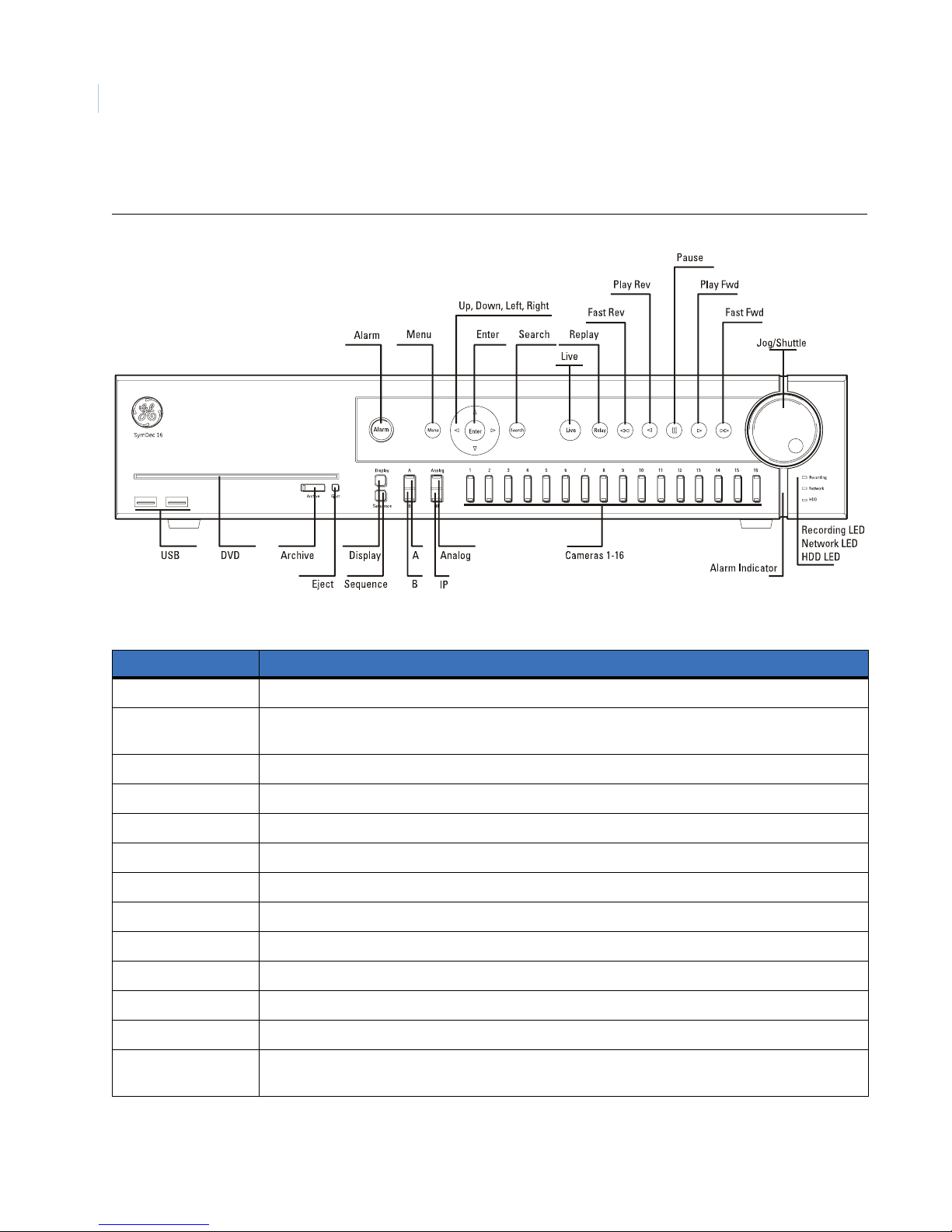
Figure 3. SymDec 16 plus 4 front panel
Table 3. Front panel controls
Control Use
Alarm button LED glows red to indicate an alarm condition. Push to silence current alarm.
Menu button Touch to enter OSD and enter Setup mode. In Setup mode, touch to discard changes and return to the
next highest level menu or exits OSD.
Arrow buttons Use to navigate menus.
Enter button In Setup mode toggles in and out of editable fields. In Playback mode starts Cameo mode.
Search button Touch to display the Search and Disk Analysis screen.
Live button Touch to stop all video playback and return to showing live video.
Replay button Touch to jump the play marker back x seconds. Configured in Front Panel on page 52.
Fast reverse button Touch to play video in reverse. Touch again to increase speed.
Play reverse button Touch to play video in reverse at 1X speed.
Pause button Touch to freeze all video at the current play marker.
Play forward button Touch to play video at 1X speed.
Fast forward button Touch to play video. Touch again to increase speed.
Jog/Shuttle During playback, rotate the shuttle (the outer dial) to increase playing speed. Use the jog to pause and
view video frame by frame.
Page 21
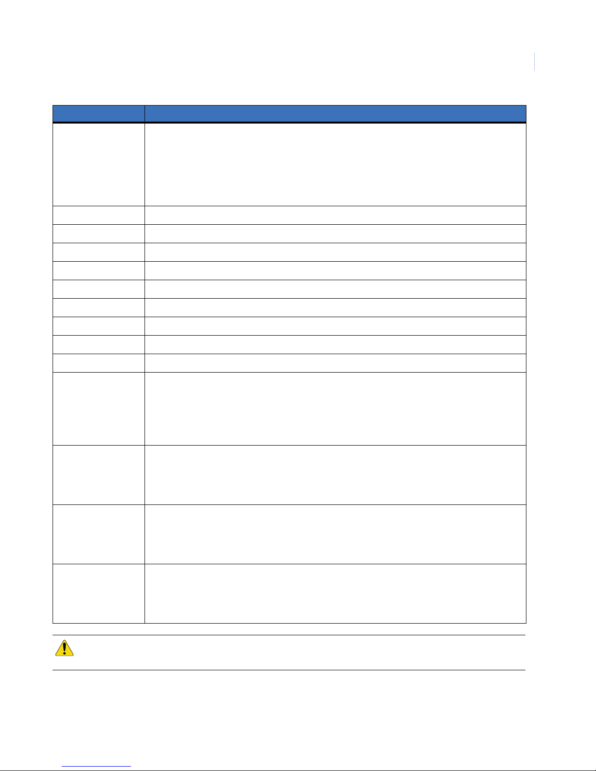
Control Use
Connections and Controls
Chapter 2
11
Alarm Indicator
Mimics the most severe status level of the alarm LED’s (Camera, Recording, Network, or HDD LED)
Red (flash bright). If any alarm LED is flashing red, or
Red (solid bright). If any alarm LED is solid red, or
Green (solid bright). If all status is okay on all alarm LED’s.
Off. Power off.
USB connectors Connects to compatible USB devices such as a flashdrive.
DVD recorder Use to archive video. See caution below.
Archive button Push to initiate Archive mode.
Eject button Push to eject DVD-R from drive.
Display button Push to cycle through available multiscreen options for monitor A.
Sequence button Push to start Sequence mode. Default sequence is analog cameras 1-16, then IP cameras 1-4.
Monitor A/B buttons Controls which monitor will be affected by the analog/IP camera controls.
Analog/IP button Controls which camera is selected when the camera buttons are pressed.
Camera buttons Push to display the selected camera in fullscreen. In Setup mode used to input numerical data.
Camera LED
(Analog 1-16 and
IP 1-4)
Green (solid bright): Connected and working properly, awake mode.
Green (solid dim): Connected and working properly, stealth mode.
Red (flashing): Alarm detected, not acknowledged, or in Videoloss.
Red (solid): Alarm detected, acknowledged.
Off, camera is disabled.
Recording LED Green (solid bright): Recording properly, awake mode.
Green (solid dim): Recording properly, stealth mode.
Red (flashing): Recording failure, not acknowledged.
Red (solid): Recording failure, acknowledged.
Network LED Green (solid bright): Connected and working properly, awake mode.
Green (solid dim): Connected and working properly, stealth mode.
Red (flashing): Connection failure alarm, not acknowledged.
Red (solid): Connection failure alarm, acknowledged.
HDD LED Green (solid bright): Working properly, awake mode.
Green (solid dim): Working properly, stealth mode.
Red (flashing): Disk failure alarm, not acknowledged.
Red (solid): Disk failure alarm, acknowledged.
CAUTION
Do not use CD/DVD’s with paper labels attached to the surface of the CD/DVD. The label’s surface may
become damaged and cause the CD/DVD media to become stuck inside the DVD recorder.
Page 22
SymDec 16 plus 4
12
User Manual
Back Panel Connections
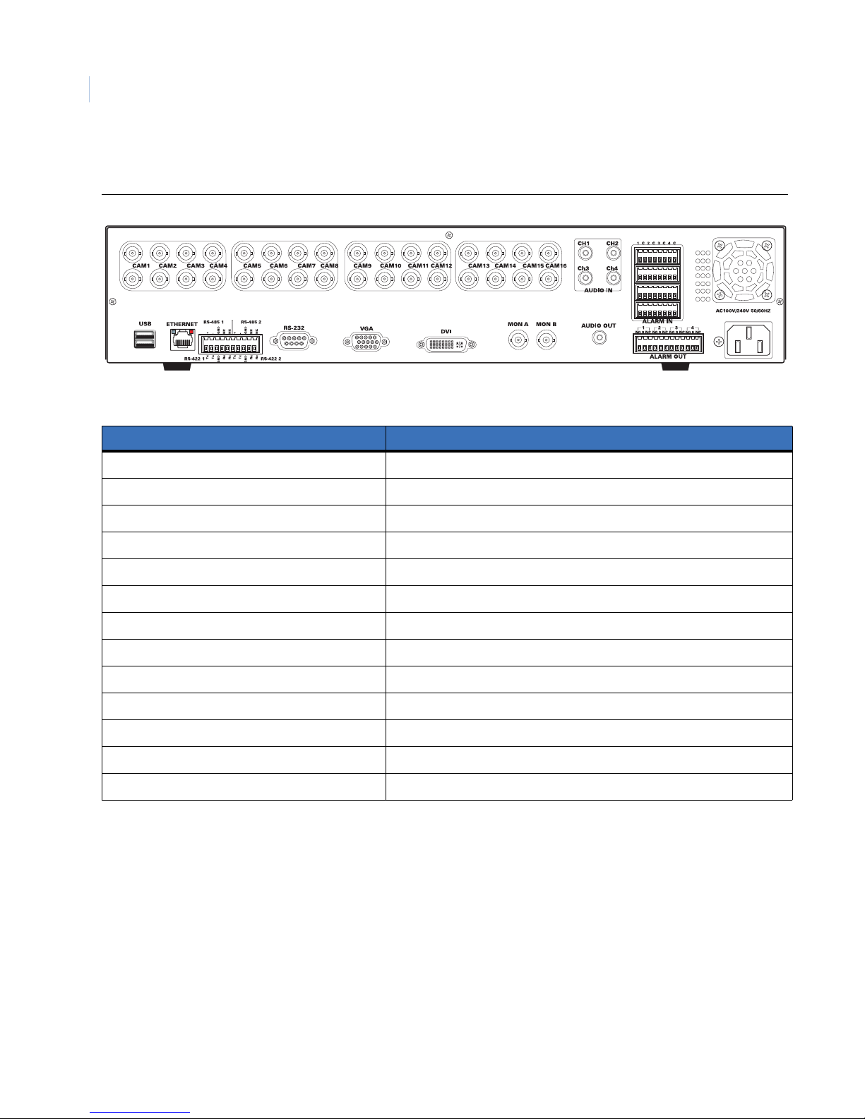
Figure 4. SymDec 16 plus 4 back panel
Table 4. Back panel connectors
Connector Use
Video In/Out Camera Inputs 1-16, BNC connector, looping, and auto-terminating.
Audio inputs 4 channels of line-level audio inputs with RCA connectors.
Alarm inputs 16 channels of alarm inputs.
USB connectors 2 USB connectors for flashdrives or a USB compatible mouse.
Ethernet port For connecting to a Network.
Serial inputs (RS-485/RS-422) 2 RS-422 or 2 RS-485 serial ports.
RS-232 connector 1 RS-232 serial port.
VGA connector For connecting to a standard VGA monitor.
DVI connector For connecting to a Digital Video Interface monitor.
Monitor A/B Composite video output for monitors A and B.
Audio out Line-level audio output with a RCA connector.
Alarm out connector 4-channel alarm outputs.
Power connector For connecting the power cord.
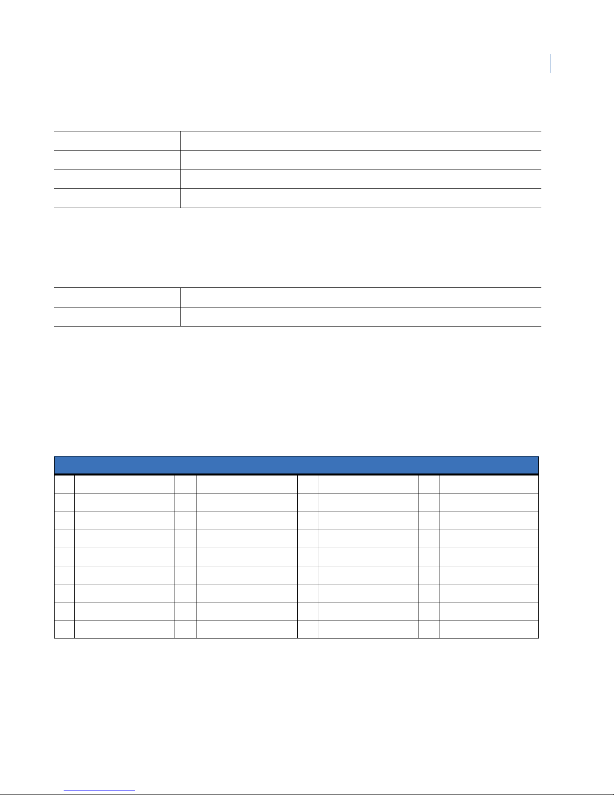
Camera Inputs
There are two BNC jacks for each camera. Either jack can receive a camera signal. The signal is looped
(directly connected to the other jack), making the camera signal available to other equipment.
The camera input connectors are auto terminating.This means that the input signal will automatically be
terminated with 75-Ohms unless a 2
Make sure there is 75-Ohm termination at the end of the video line if the signal is looped through the SymDec
16 plus 4.
nd
cable is connected to the 2nd BNC connector of the same camera input.
Page 23
Connections and Controls
Chapter 2
Time base correction is performed during digital capture. As a result, cameras do not require synchronization.
Cable 75-Ohm coaxial
Connectors BNC
Auto terminating Yes
Passive looping Yes
Audio Inputs and Output
The unit is equipped with 4 audio inputs and 1 audio output. Both the audio output and the audio inputs are
line-level.The 4 audio inputs are associated with the first 4 cameras.
Audio input RCA jack, 315 mV, 40k Ohms. Unbalanced
Audio out RCA jack, 315mV, 600 Ohms. Unbalanced
Note: Line-level audio requires amplification.
13
Alarm Inputs
Four 8-pin connectors on the back panel provide the connections for the alarm inputs. Connect the wires to the
4 terminating connectors provided with the SymDec 16 plus 4. See the table below for a description of the
pinouts.
Table 5.
Alarm IN connector
Pin Signal Pin Signal Pin Signal Pin Signal
1 Alarm Input 1 N/Open 5 Alarm Input 5 N/Open 9 Alarm Input 9 N/Open 13 Alarm Input 13 N/Open
C Alarm Input 1 Common C Alarm Input 5 Common C Alarm Input 9 Common C Alarm Input 13Common
2 Alarm Input 2 N/Open 6 Alarm Input 6 N/Open 10 Alarm Input 10 N/Open 14 Alarm Input 14 N/Open
C Alarm Input 2 Common C Alarm Input 6 Common C Alarm Input 10 Common C Alarm Input 14 Common
3 Alarm Input 3 N/Open 7 Alarm Input 7 N/Open 11 Alarm Input 11 N/Open 15 Alarm Input 15 N/Open
C Alarm Input 3 Common C Alarm Input 7 Common C Alarm Input 11 Common C Alarm Input 15 Common
4 Alarm Input 4 N/Open 8 Alarm Input 8 N/Open 12 Alarm Input 12 N/Open 16 Alarm Input 16 N/Open
C Alarm Input 4 Common C Alarm Input 8 Common C Alarm Input 12 Common C Alarm Input 16 Common
Note: Do not attempt to wire any accessories directly to the I/O connector on the back panel. These connections require dry
contact (voltage free) closure to activate.
USB connectors
Industry compatible USB connectors for use with flashdrives for updating the SymDec 16 plus 4.
Page 24
SymDec 16 plus 4
14
User Manual
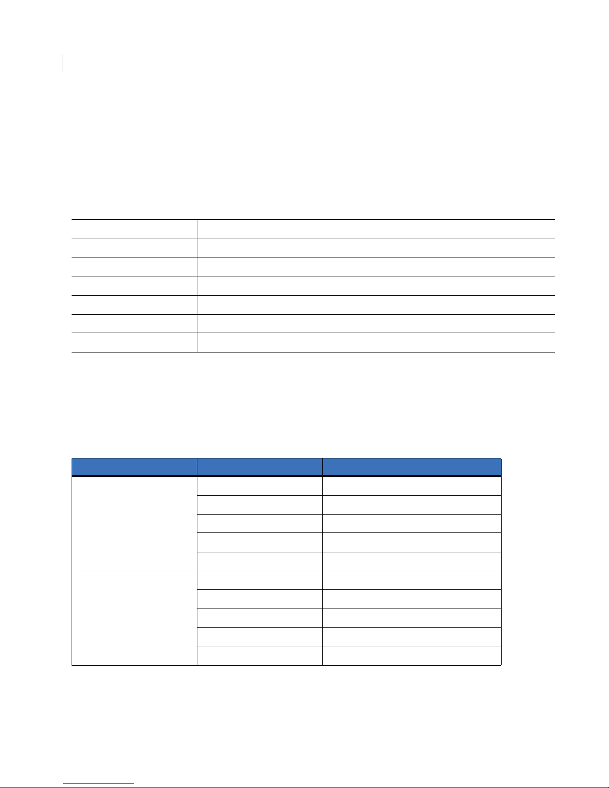
Ethernet Port
The cable connection configuration for the ethernet port depends on your network configuration:
• For a SymDec 16 plus 4 that connects directly to a hub, use a straight through connection.
• For a SymDec 16 plus 4 that connects directly to a PC, use a cross-over connection.
Consult with your network administrator or IS professional for the specific type of configuration. See The
Network menu on page 59 for information about configuring the Ethernet settings in the menu system
Ethernet 10/100/1000 Base-T, auto sensing
Wire type Cat 5e/6
Connector type RJ-45
Maximum cable length 328 feet/100 meters
Minimum cable length 6 feet/1.8 meters
Hub wiring configuration Straight through
PC wiring configuration Cross-over
RS-485/RS-422 I/O connectors
These (2) serial I/O ports can be configured as either RS-485 or RS-422 and are used for Pan, Tilt, Zoom
control of PTZ cameras. Use Serial Communications on page 78 to configure these ports. See tables 6 and 7 for
the serial pinouts for each configuration.
Table 6. RS-485 1 and 2 port pinouts
Port type Pin Description
RS-485 (1) 1 +
2-
3Ground
4Not connected
5Not connected
RS-485 (2) 6 +
7-
8Ground
9Not connected
10 Not connected
Page 25
.
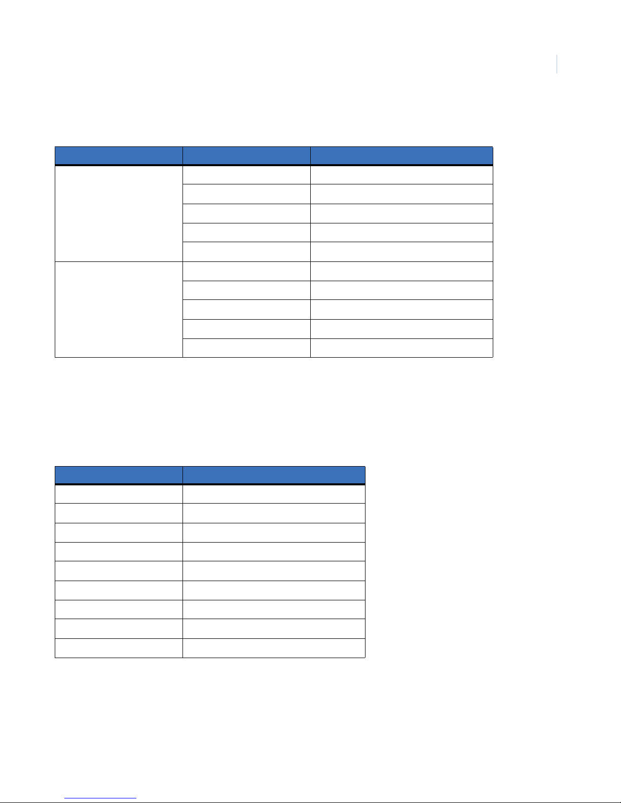
Table 7. RS-422 1 and 2 port pinouts
Port type Pin Description
RS-422 (1) 1 TX+
2TX-
3Ground
4RX+
5RX-
RS-422 (2) 6 TX+
7TX-
8Ground
9RX+
10 RX-
Connections and Controls
Chapter 2
15
RS232 Port
The RS232 port is provided for use with GE's ProBridge text insertion interface modules in conjuction with
compatible POS (point of sale) and ATM (automated teller machine) systems. Use Serial Communications on
page 78 to configure this port.
Table 8. RS232 port pinouts
Pin Description
1DCD
2RX
3TX
4DTR
5Grounded
6Not connected
7RTS
8CTS
9Not connected
VGA connector
The 15-pin VGA connector is provided for connection to a standard VGA monitor for monitoring video.
Page 26
SymDec 16 plus 4
16
User Manual
DVI connector
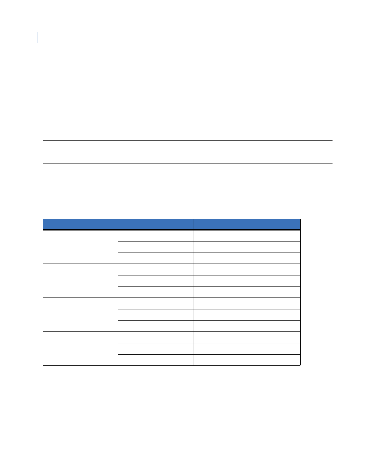
The DVI (Digital Video Interface) is provided for connection to high-speed, high-resolution digital displays.
Monitor A/B composite output
When connecting directly from the SymDec 16 plus 4 to the monitor, select the 75-Ohm impedance setting on
the monitor. If an additional device is connected to the monitor’s looping output, set the termination of the
additional device as 75-Ohm, and set the termination of the monitor as Hi-Z (High Impedance).
Cable 75-Ohm
Connectors BNC
Alarm out connector
The 4 Alarm out connectors are provided for connections to audio/visual alarm notification devices such as
sirens and warning lights.
Table 9. Alarm out port pinouts
Alarm out number Pin Description
Alarm out 1 1 NO (Normally open)
2 C (Common)
3 NC (Normally closed)
Alarm out 2 1 NO (Normally open)
2 C (Common)
3 NC (Normally closed)
Alarm out 3 1 NO (Normally open)
2 C (Common)
3 NC (Normally closed)
Alarm out 4 1 NO (Normally open)
2 C (Common)
3 NC (Normally closed)
Page 27
Connections and Controls
Chapter 2
Power Connector
Plug the power cord into the power cord connector and then into a properly rated wall socket. Once power is
applied to the unit, it will begin its power-up procedure. The unit will begin by displaying the software version
on Monitor-A, then the unit will begin recording automatically.
Table 10. Power supply rating
Power supply
Voltage 100-240 VAC 50-60 Hz, auto-ranging
Amps 5
17
Page 28
SymDec 16 plus 4
18
User Manual
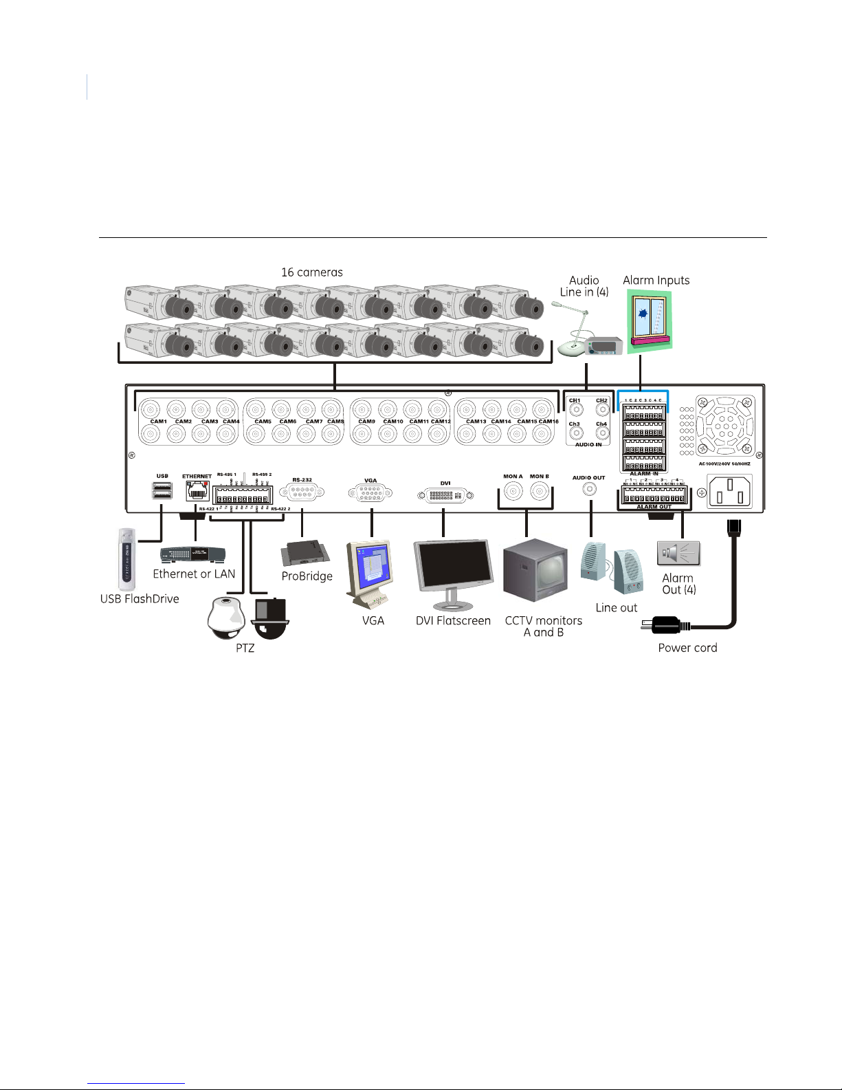
Connection Diagrams
Use the figures on the following pages a visual guide to connect the various peripherals to the SymDec 16 plus
4.
Figure 5. Rear panel connection diagram
Page 29
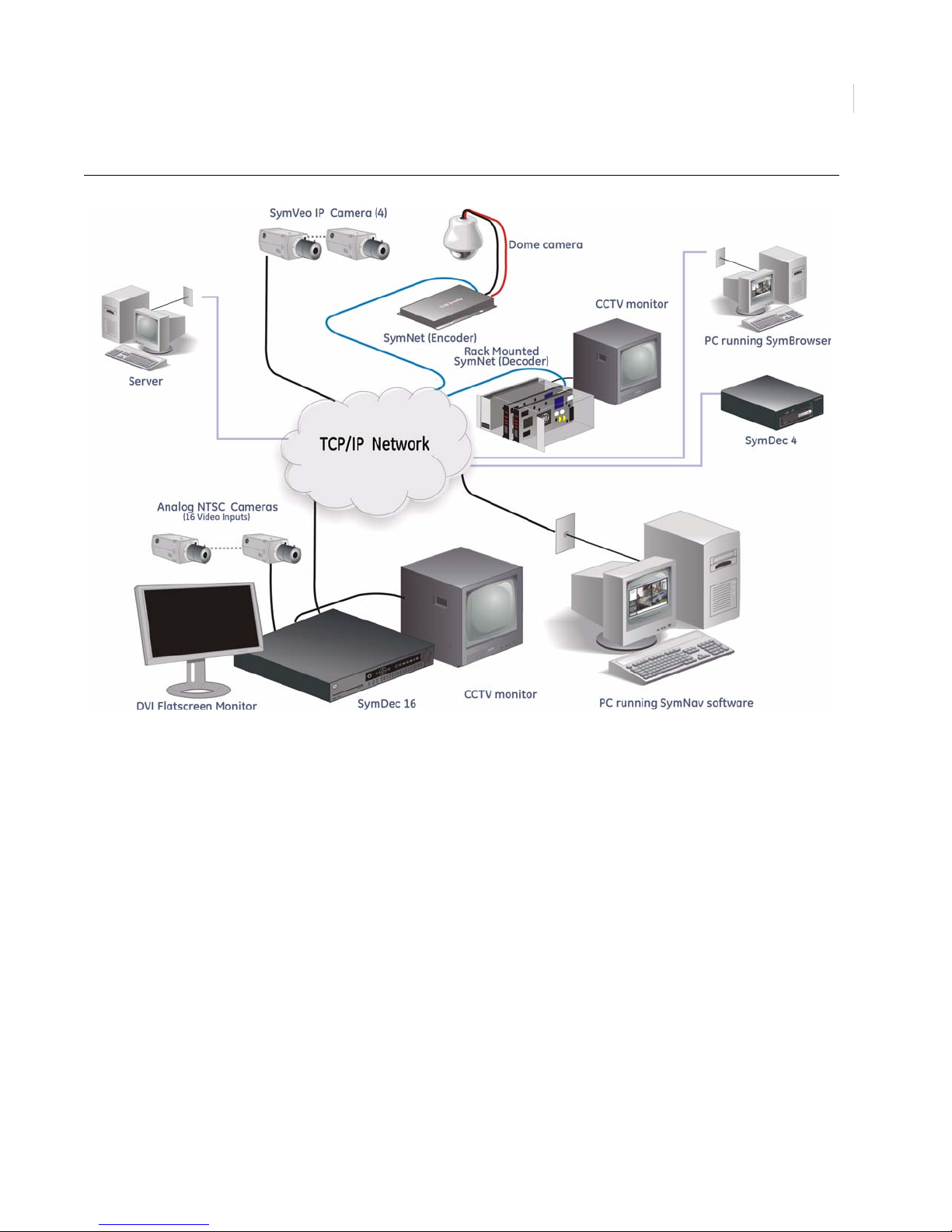
Figure 6. Sample network diagram
Connections and Controls
Chapter 2
19
Page 30
SymDec 16 plus 4
20
User Manual
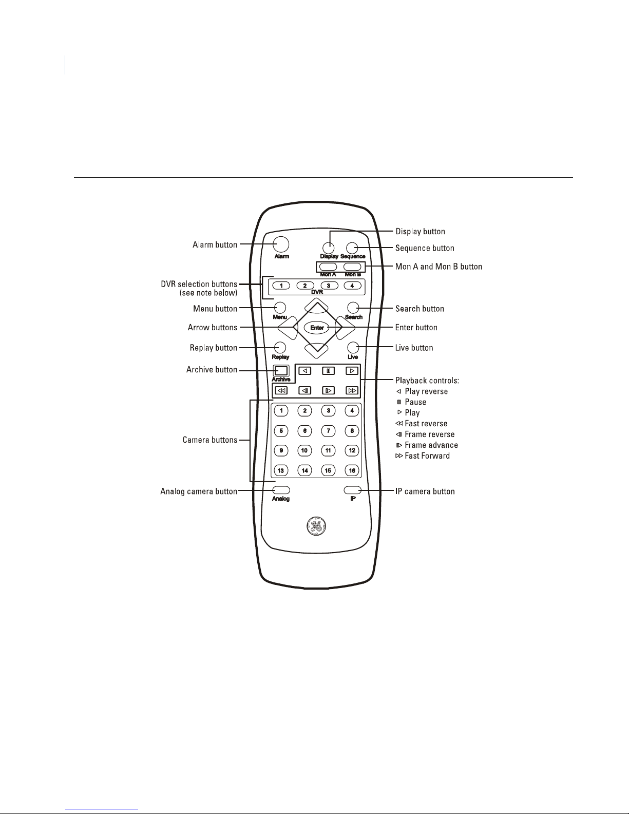
The Remote Controller
The SymDec 16 plus 4 is supplied with an Infra Red (IR) remote control unit. It can be used to o perate many of
the main functions of the SymDec 16 plus 4 and can be programmed to work with up to 4 SymDec 16 plus 4’ s.
Figure 7. The remote control unit
Note: The remote controller can be programmed with a unique address (1-4) so that the controller will only be able to
communicate with unit’s with that address. See Front Panel on page 52 to program.
Page 31

Chapter 3 Basic Operations
This chapter provides procedures for performing some of the basic operations of
the SymDec 16 plus 4 from logging in to creating an archive disk.
In this chapter:
Front Panel Controls . . . . . . . . . . . . . . . . . . . . . . . . . . . . . . . . . . . . . . . 22
Operations . . . . . . . . . . . . . . . . . . . . . . . . . . . . . . . . . . . . . . . . . . . . . . . 24
How to Log In. . . . . . . . . . . . . . . . . . . . . . . . . . . . . . . . . . . . . . . . . . 24
How to change the display for Monitor A and Monitor B . . . . . . . . 24
How to change the display to a full-screen analog view . . . . . . . . . 24
How to change the display to a full-screen IP view. . . . . . . . . . . . . 24
How to view multiscreen displays . . . . . . . . . . . . . . . . . . . . . . . . . . 24
How to change the display presets. . . . . . . . . . . . . . . . . . . . . . . . . . 25
How to enter Cameo mode. . . . . . . . . . . . . . . . . . . . . . . . . . . . . . . . 25
How to display Sequencing . . . . . . . . . . . . . . . . . . . . . . . . . . . . . . . 25
How to return to the default sequence list . . . . . . . . . . . . . . . . . . . . 25
How to enter Playback mode . . . . . . . . . . . . . . . . . . . . . . . . . . . . . . 25
How to Search using Disk Analysis . . . . . . . . . . . . . . . . . . . . . . . . . 26
How to Search using the Filters Screen . . . . . . . . . . . . . . . . . . . . . . 26
How to archive from the Search screen . . . . . . . . . . . . . . . . . . . . . . 26
How to use the Archive screen. . . . . . . . . . . . . . . . . . . . . . . . . . . . . 27
How to setup and stream an IP camera to a SymDec 16. . . . . . . . . 27
How to setup a KTD-405 keypad to work with the SymDec 16 . . . . 28
How to set the IP camera option to a keypad button. . . . . . . . . . . . 28
KTD-405 keypad mapping to SymDec 16 front panel . . . . . . . . . . . 29
Page 32
SymDec 16 plus 4
22
User Manual
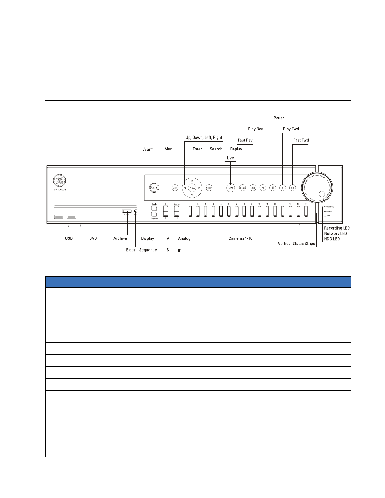
Front Panel Controls
The front panel is shown here as quick reference for the procedures that follow.
Figure 8. SymDec 16 plus 4 front panel
Table 11. Front panel controls
Control Use
Alarm button LED glows red to indicate an alarm condition. Push to silence current alarm.
Menu button Touch to enter OSD and enter Setup mode. In Setup mode, touch to discard changes and return to the
next highest level menu or exits OSD.
Arrow buttons Use to navigate menus.
Enter button In Setup mode toggles in and out of editable fields. In Playback mode starts Cameo mode.
Search button Touch to display the Search and Disk Analysis screen.
Live button Touch to stop all video playback and return to showing live video.
Replay button Touch to jump the play marker back x seconds. Configured in Front Panel on page 52.
Fast reverse button Touch to play video in reverse. Touch again to increase speed.
Play reverse button Touch to play video in reverse at 1X speed.
Pause button Touch to freeze all video at the current play marker.
Play forward button Touch to play video at 1X speed.
Fast forward button Touch to play video. Touch again to increase speed.
Jog/Shuttle During playback, rotate the shuttle (the outer dial) to increase playing speed. Use the jog to pause and
view video frame by frame.
Page 33
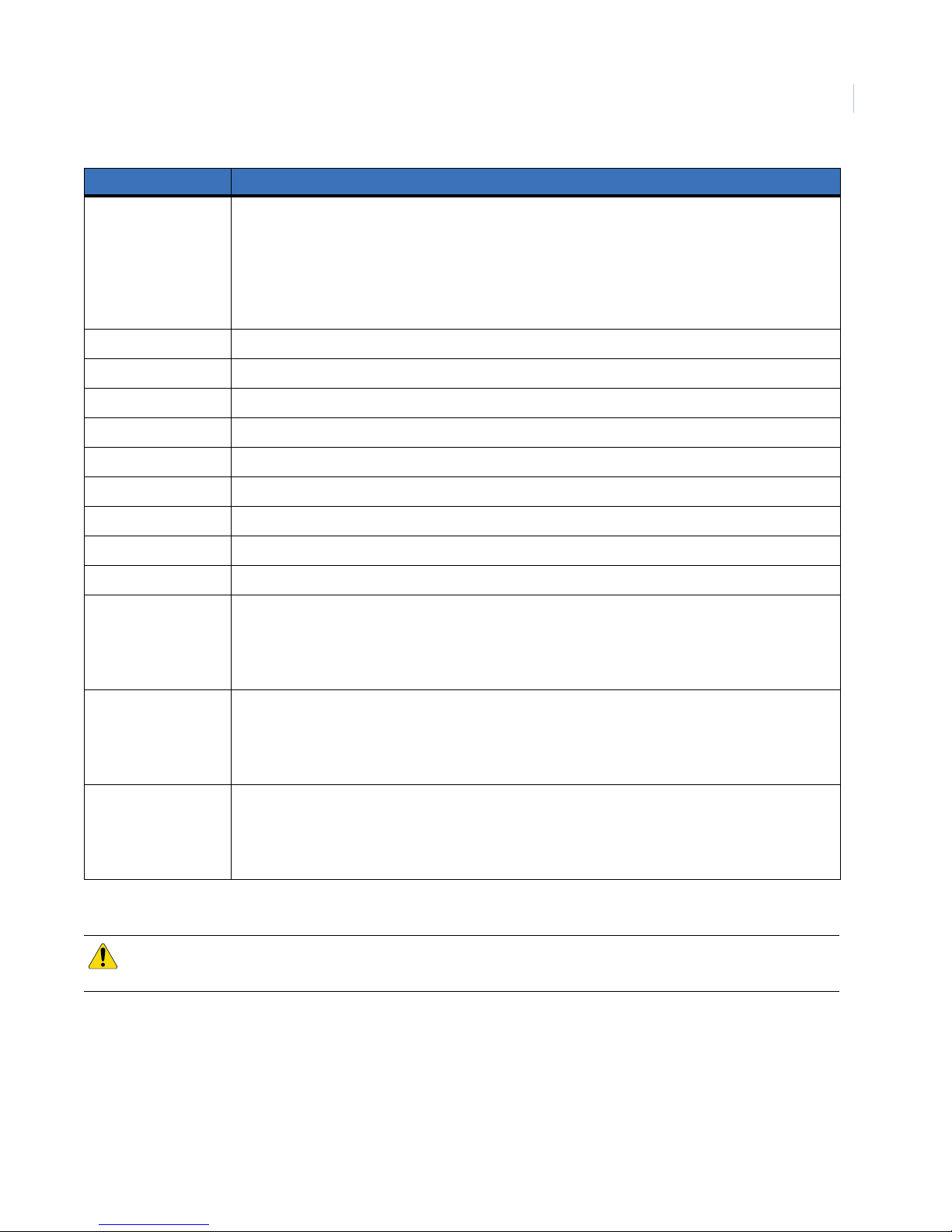
Control Use
Chapter 3
Basic Operations
23
Vertical status stripe
Mimics the most severe status level of the alarm LED’s (Camera, Recording, Network, or HDD LED)
Red (flash bright). If any alarm LED is flashing red, or
Red (solid bright). If any alarm LED is solid red, or
Green (solid bright). If all status is okay on all alarm LED’s.
Off. Power off.
USB connectors Connects to compatible USB devices such as a flashdrive.
DVD recorder Use to archive video. See caution below.
Archive button Push to initiate Archive mode.
Eject button Push to eject DVD-R from drive.
Display button Push to cycle through available multiscreen options for monitor A.
Sequence button Push to start Sequence mode. Default sequence is analog cameras 1-16, then IP cameras 1-4.
Monitor A/B buttons Controls which monitor will be affected by the analog/IP camera controls.
Analog/IP button Controls which camera is selected when the camera buttons are pressed.
Camera buttons Push to display the selected camera in fullscreen. In Setup mode used to input numerical data.
Recording LED Green (solid bright): Recording properly, awake mode.
Green (solid dim): Recording properly, stealth mode.
Red (flashing): Recording failure, not acknowledged.
Red (solid): Recording failure, acknowledged.
Network LED Green (solid bright): Connected and working properly, awake mode.
Green (solid dim): Connected and working properly, stealth mode.
Red (flashing): Connection failure alarm, not acknowledged.
Red (solid): Connection failure alarm, acknowledged.
HDD LED Green (solid bright): Working properly, awake mode.
Green (solid dim): Working properly, stealth mode.
Red (flashing): Disk failure alarm, not acknowledged.
Red (solid): Disk failure alarm, acknowledged.
CAUTION
Do not use DVD’s with paper labels attached to the surface of the DVD. The label’s surface may become
damaged and cause the DVD media to become stuck inside the DVD recorder.
Page 34

SymDec 16 plus 4
24
User Manual
Operations
The following sections provide step-by-step instructions on some of the SymDec 16 plus 4’s most common
operations.
How to Log In
To log in to the Symdec 16 plus 4 do the following:
1. Press the Menu button on the front panel or remote control.
2. Use the arrow buttons to select your user account and press Enter to finish.
3. Input your PIN code, using the camera number buttons on the front panel or remote camera buttons.
Select Done when finished.
4. You should now be logged in. Depending on your permissions, you can now access Search, Archive,
the front panel controls and the OSD menus.
How to change the display for Monitor A and Monitor B
1. To control live and playback functions and access the menus, press the Mon A button.
2. To c han ge the display of live video on the secondary display, press the Mon B button.
How to change the display to a full-screen analog view
1. Press the Analog button if the LED is not lit to enable the analog camera buttons.
2. Press the camera number (1-16) of the camera you wish to view full-screen.
How to change the display to a full-screen IP view
1. Press the IP button if the LED is not lit to enable the IP camera buttons.
2. Press the camera number (1-4) of the IP camera you wish to view full-screen.
How to view multiscreen displays
1. Select the display to view the multiscreens by pressing the Mon A or B button.
2. Press the Display button to toggle through the available multiscreen displays.
3. Display sequence for Mon A is full-screen, 4-up, 9-up, 16-up. Display sequence for Mon B is fullscreen and 4-up.
Page 35

Basic Operations
How to change the display presets
1. Press and hold the Display button on the front panel.
2. The Display Preset screen will appear.
3. Select from the ten displayed options by pressing the corresponding camera button.The selected screen
replaces the factory default display.
How to enter Cameo mode
A cameo is defined as any cell in a multiscreen display.
1. From any multiscreen display, use the arrow buttons to move the selection box to a selected display
and press enter.
2. Press the IP or Analog button followed by a camera number button.
How to display Sequencing
Chapter 3
25
The sequencing feature allows a camera to be displayed briefly on-screen, before advancing to the next camera
in the sequence list. The default sequence list displays each camera in numerical order.
From Full Screen
1. Press any camera number to enter fullscreen mode.
2. Press the Sequence button to begin automatic sequencing.
From Multiscreen
1. While in a multiscreen display , use the arrow buttons to move the selection box to the camera you wish
to display sequencing and press enter.
2. Press the Sequence button to begin automatic sequencing in that cameo.
How to return to the default sequence list
1. Press and hold the Display button to reset all screens to the default.
2. Select number nine to return to the default screen list.
How to enter Playback mode
From Multiscreen
1. In multiscreen mode, move the selection box to the desired camera and press enter.
2. Press play. Th e se le cted camera is now in playback.
Page 36

SymDec 16 plus 4
26
User Manual
To return to Live mode
1. With the selection box on the playback display cameo press enter.
2. Press the Live button. The selected display is now in live mode.
How to Search using Disk Analysis
1. Press the Search button to bring up the Disk Analysis and Filters menu.
2. Press enter to use the Disk Analysis screen.
3. Press the left and right arrow buttons to move the time cursor backward or forward through the
available video.
4. Press the Up arrow button to zoom out and the down arrow button to zoom in.
5. Use arrow buttons to find the video you want to view, then press enter to preview the video. Press Play
to begin playback.
6. Press a camera button to view the playback fullscreen.
How to Search using the Filters Screen
1. Press the Search button to bring up the Disk Analysis and Filters menu.
2. Press the up/down arrow buttons to select the desired filter. Y ou can filter by Date and Time, Cameras
or Motion, Alarms/Events, or Text and Time of Day.
3. Press enter to change the filter mode and settings.
4. Change the filter as desired and Press Menu button to return to the top level menu.
5. When you have set all the filters, Select Search Now and Press enter. The Thumbnail Previews screen
will appear.
6. From the Thumbnail Previews screen select the video you which to review and press enter to begin
previewing the video in playback.
How to archive from the Search screen
1. With the Thumbnail Previews screen displayed, use the playback controls to move the video to the
desired Start Time for the archive and select Set Start then Press enter.
2. Now advance the video using the playback controls to the desired Stop Time for the archive and select
Set Stop and Press enter.
3. Select Archive and press enter. You a r e now in the Archive Screen.
4. Either insert a blank optical disc in the DVD Burner slot or plug in a USB storage device into the front
panel USB connector.
5. Press enter to change the media and Press enter to confirm the selection.
6. Press the down arrow to select the Archive Name. Press enter and use the on-screen keyboard to
change the name of the file to be exported. Select Done and press enter when finished.
Page 37

Basic Operations
7. Press the down arrow to select the Include Player checkbox. Check to include the GE SymPlayer, or
uncheck if you have previously installed the player or will play the video in SymNav.
8. Press the down arrow and use the Camera List block to select the cameras within the Start and Stop
window to be exported. Be sure the Archive Size is smaller than the archive media. You may need to
change the Start and Stop by returning to the Thumbnail Previews screen or select fewer camera
channels to make it fit.
9. Press the down arrow until you Select Archive Now; Press enter to begin the export. You may safely
remove the media once the Archive Complete message is shown.
How to use the Archive screen
1. Press the Archive button on the front panel. The Archive Screen will appear.
2. Insert a blank optical disc in the DVD Burner slot or plug in a USB storage device into the front panel
USB connector.
3. Press enter to change the media and Press enter to confirm the selection.
4. Press the down arrow to select the Archive Name. Press enter and use the on-screen keyboard to
change the name of the file to be exported. Select Done and press enter when finished.
Chapter 3
27
5. Press the down arrow to select the archive length. The Archive S top Time was set when you pressed the
Archive button. Press enter and adjust the length to change the Start Time. Press enter to confirm the
length.
6. Press the down arrow to select the Include Player checkbox. Check to include the GE SymPlayer, or
uncheck if you have previously installed the player or will play the video in SymNav.
7. Press the down arrow and use the Camera List block to select the cameras within the Start and Stop
window to be exported. Be sure the Archive Size is smaller than the archive media. You may need to
change the Start and Stop by selecting fewer camera channels to make it fit.
8. Press the down arrow until you Select Archive Now; Press enter to begin the export. You may safely
remove the media once the Archive Complete message is shown.
How to setup and stream an IP camera to a SymDec 16
1. Set the IP address and the St reaming/Multicast address on the IP camera. This is done through the
camera’s setup menu.
2. Select the Camera menu from the Main menu on the SymDec 16.
3. Select the IP camera number that you are going to setup.
4. Input the camera’s IP address in the Source Address field in the Recording menu.
5. Press the Menu button twice to return to the Main menu.
6. Select the Network menu.
7. Select the IP advanced menu.
8. Enter the camera’s Streaming/Multicast address into the Multicast field. This address always starts
with the number 230. (230.xxx.xxx.xxx)
Page 38

SymDec 16 plus 4
28
User Manual
Example
•The DVR IP address is 168.125.115.010
•The Camera IP address is 168.125.115.025 (both in the camera itself and SymDec 16 camera menu)
•The Multicast/Streaming address on both the camera and SymDec 16 should be 230.125.115.025
• If you have a second IP camera: The Camera IP Address could be 168.125.115.026 and the Multicast/
Streaming address would still be 230.125.115.025
How to setup a KTD-405 keypad to work with the SymDec 16
T o setup and connect a KTD-405 keypad and a Symdec 16 follow the steps below. You will need to refer to the
KTD-405 user manual (part number 1036547D).
1. Connect a pair of wires from the KTD-405 I/O box to the SymDec 16 Bus 1/ 485 port.
• KTD-405 I/O box pin RS485 (A) to SymDec 16 Serial I/O Bus 1/485 pin 1 (+).
• KTD-405 I/O box pin RS485 (B) to SymDec 16 Serial I/O Bus 1/485 pin 2 (-).
2. Verify the serial communication settings on Bus 1 of the Symdec 16;
a. Go to the System/Serial Communication Bus 1 menu and verify the following:
• Bus 1 Type: RS-0485
• Protocol: Kalatel
• Baud Rate: 9600
• DVR Addr: 1
3. Enter Zone mode operation on the KTD405 keypad. Please refer to your KTD-405 manual for more
detailed information. Access the KTD-405 zone mode by doing:
a. Hold down the Enter key.
b. Enter programming code: 5-7-9-seq.
c. Change operating mode from Digiplex to Zone mode by the joystick up/down.
d. Press the Fast Forward button.
e. Hold down the Seq button to exit the menu.
f. You should be in Zone mode.
g. Press the Zone button, then the number 1. This will initiate a connection between the SymDec 16
and the KTD-405 keypad.
How to set the IP camera option to a keypad button
The KTD-405 and SymDec 16 should be connected and op erational.
1. Hold down the Enter button on the KTD-405.
2. Enter programming code: 1-4-7-6-seq.
3. Press the fast forward button until you get to the Program Soft Keys option.
4. Press the + button.
Page 39
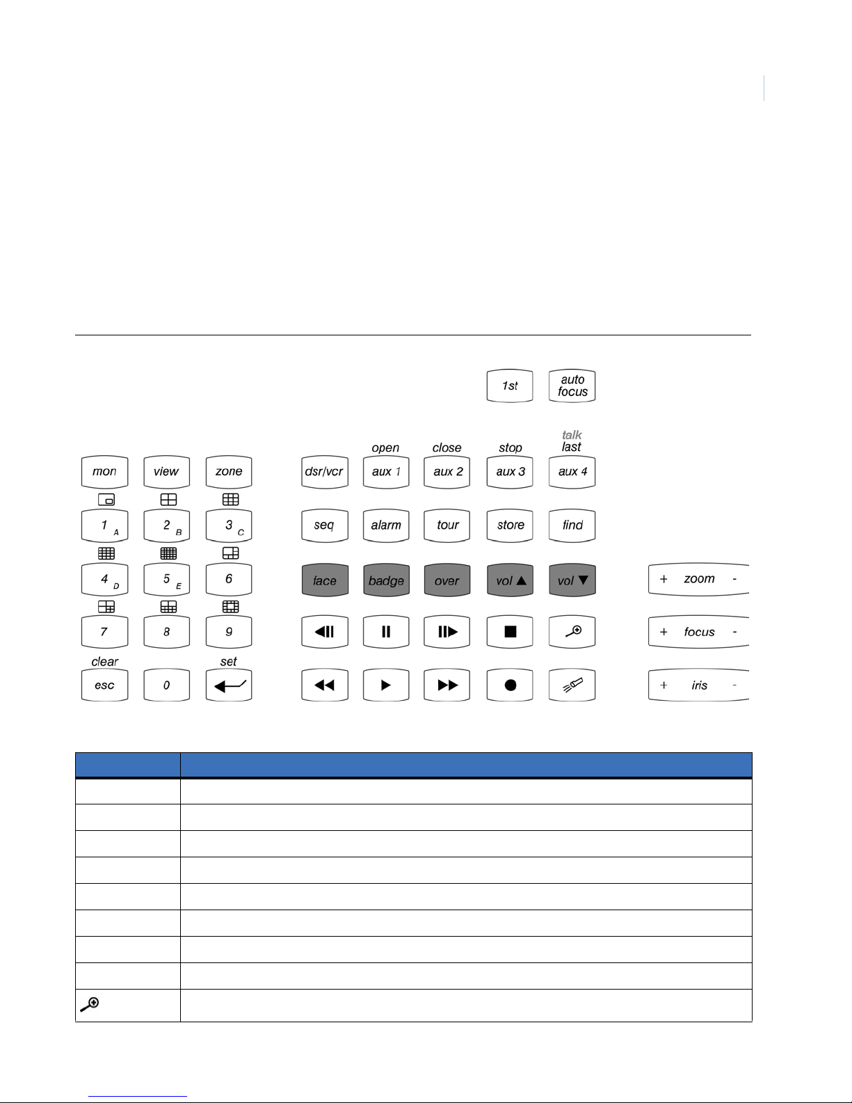
5. When it says Press key to pr ogram, press the magnifying glass icon.
6. Move the joystick up until you reach the ALT option.
7. Press the Enter and the + button to confirm the change.
8. Press the Seq button to exit programming mode.
9. You should now be able to select the IP camera by pressing the magnifying glass icon.
KTD-405 keypad mapping to SymDec 16 front panel
Figure 9. KTD-405 panel buttons
Chapter 3
Basic Operations
29
Table 12. KTD-405 to SymDec 16 front panel mapping
KTD-405 Keypad SymDec 16 front panel function
Replay button: In playback mode, touch to jump the play marker back x seconds.
Play forward button: plays video at 1x speed.
Live button: Stops video playback and returns to showing live video.
Pause button: Freezes all video at the current play marker.
Fast forward button: In playback mode, increases play speed.
Fast reverse button: In playback mode, plays video in reverse. Touch again to increase speed.
Play forward button: Plays video forward at 1x speed.
Play reverse button: Plays video in reverse at 1x speed.
Can be configured to display selected IP camera.
Page 40
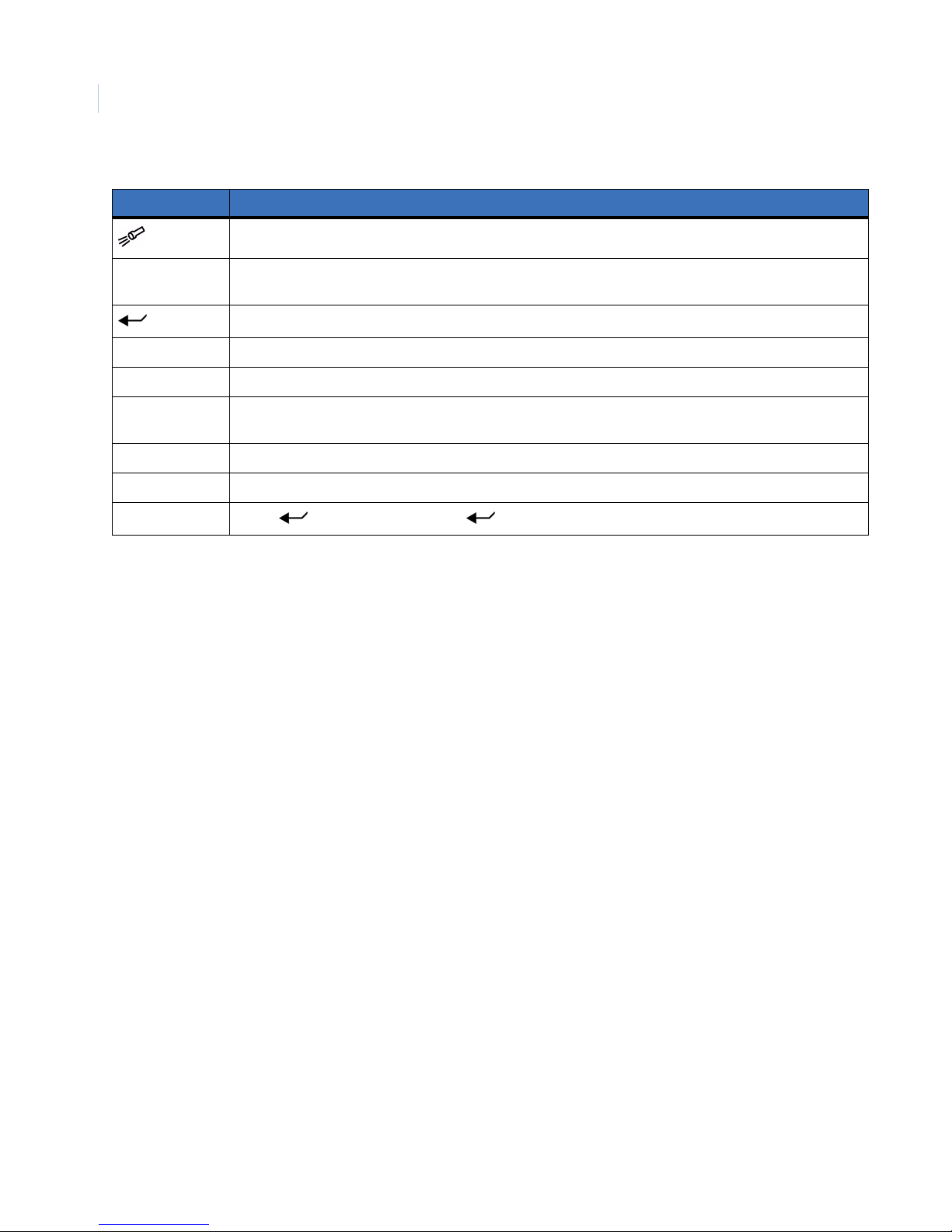
SymDec 16 plus 4
30
User Manual
Table 12. KTD-405 to SymDec 16 front panel mapping
KTD-405 Keypad SymDec 16 front panel function
Search button: Displays the Search and Disk Analysis screens.
Joystick In setup mode, scrolls up, down, left. right in menus. In play or pause modes, rotate clockwise or counter
clockwise to jog video forward or reverse.
In setup mode, emulates the Enter button. Toggles in and out of editable fields.
esc Emulates the Menu button. Push to enter OSD mode or to discard changes in menus.
Alarm Emulates the Alarm button. Push to acknowledge all alarms.
View Emulates the Display button. Push to cycle through available multiscreens. Use with the 2-5 number
buttons.
Seq Emulates the Sequence button.
Mon Use with 0 and 1 number buttons to select Monitor A or Monitor B.
Zone
Zone + + 1-16 (number buttons) + emulates Camera buttons.
Page 41

Chapter 4 Programming the SymDec 16 plus 4
This chapter provides an in-depth review of the On Screen Display (OSD). The
OSD is used to program how the SymDec 16 plus 4 operates from setting up the
password levels to the record rates of the cameras.
In this chapter:
Log In . . . . . . . . . . . . . . . . . . . . . . . . . . . . . . . . . . . . . . . . . . . . . . . . . . . 32
Cameras menu . . . . . . . . . . . . . . . . . . . . . . . . . . . . . . . . . . . . . . . . . . . . 35
The Schedule menu . . . . . . . . . . . . . . . . . . . . . . . . . . . . . . . . . . . . . . . . . 47
The Users menu . . . . . . . . . . . . . . . . . . . . . . . . . . . . . . . . . . . . . . . . . . . 57
The Network menu . . . . . . . . . . . . . . . . . . . . . . . . . . . . . . . . . . . . . . . . . 59
The Display menu . . . . . . . . . . . . . . . . . . . . . . . . . . . . . . . . . . . . . . . . . . 69
The System menu. . . . . . . . . . . . . . . . . . . . . . . . . . . . . . . . . . . . . . . . . . . 70
The Info menu . . . . . . . . . . . . . . . . . . . . . . . . . . . . . . . . . . . . . . . . . . . . . 83
Page 42
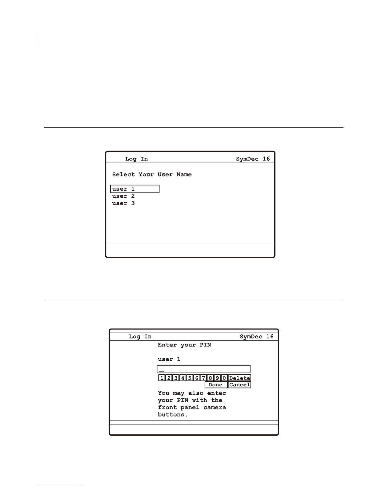
SymDec 16 plus 4
32
User Manual
Log In
To program your SymDec 16 plus 4 you must first setup a user and create a password or PIN. Make sure, at a
minimum, you have attached a monitor to view the OSD and applied power to the SymDec 16 plus 4.To setup
a user, press the Menu button on the front panel. The initial Log In screen will appear.
Note: A maximum of 24 users can be logged in at the same time.
Figure 10. The Log In screen
Use the arrow buttons to navigate, select a user and press the Enter button. The Enter Your Pin screen will
appear.
Figure 11. The Enter Your Pin screen
Page 43
Programming the SymDec 16 plus 4
Chapter 4
Enter the default password by using the Arrow and Enter buttons. You can also use the camera buttons to enter
the password.
Table 13. Default passwords
Password name Default password (PIN) Default Access level
user 1 111111 Administrator
user 2 222222 Manager
user 3 333333 Operator
When completed, navigate to the Done button and press Enter. The Main OSD menu will appear.
Main Menu
The Main menu contains the following sub-menus:
• Cameras
•Schedule
•Alarms
•Users
•Network
•Display
•System
•Info
33
Page 44
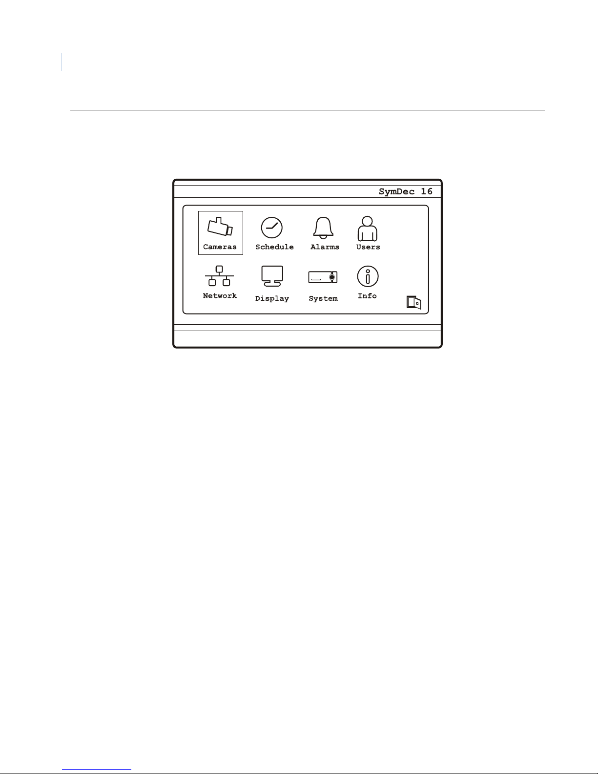
SymDec 16 plus 4
34
User Manual
Figure 12. The Main menu
Note: GE recommends that after you have completed your initial Log In you should setup up your users, passwords, and
access levels for security reasons. See The Users menu on page 57 for complete information.
Page 45
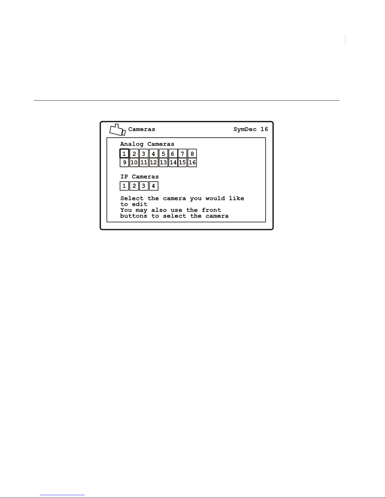
Programming the SymDec 16 plus 4
Chapter 4
Cameras menu
Highlight the Cameras icon on the Main menu and press the enter button. The Cameras menu will appear .
Figure 13. The Cameras menu
35
Select the camera type (analog or IP) and camera number which you wish to configure and press the Enter
button.The analog camera or IP camera edit menu will display.
Note: The camera number can be selected by using the arrow buttons on the front panel, the camera number buttons on the
front panel, or the camera number buttons on the remote controller.
Analog Camera menu
The Analog Camera menu contains the following options and their settings:
• Recording
• Rates
• Alarm Input
• Motion
• Camera Title
• Adjust Video
• Copy Setting
Page 46
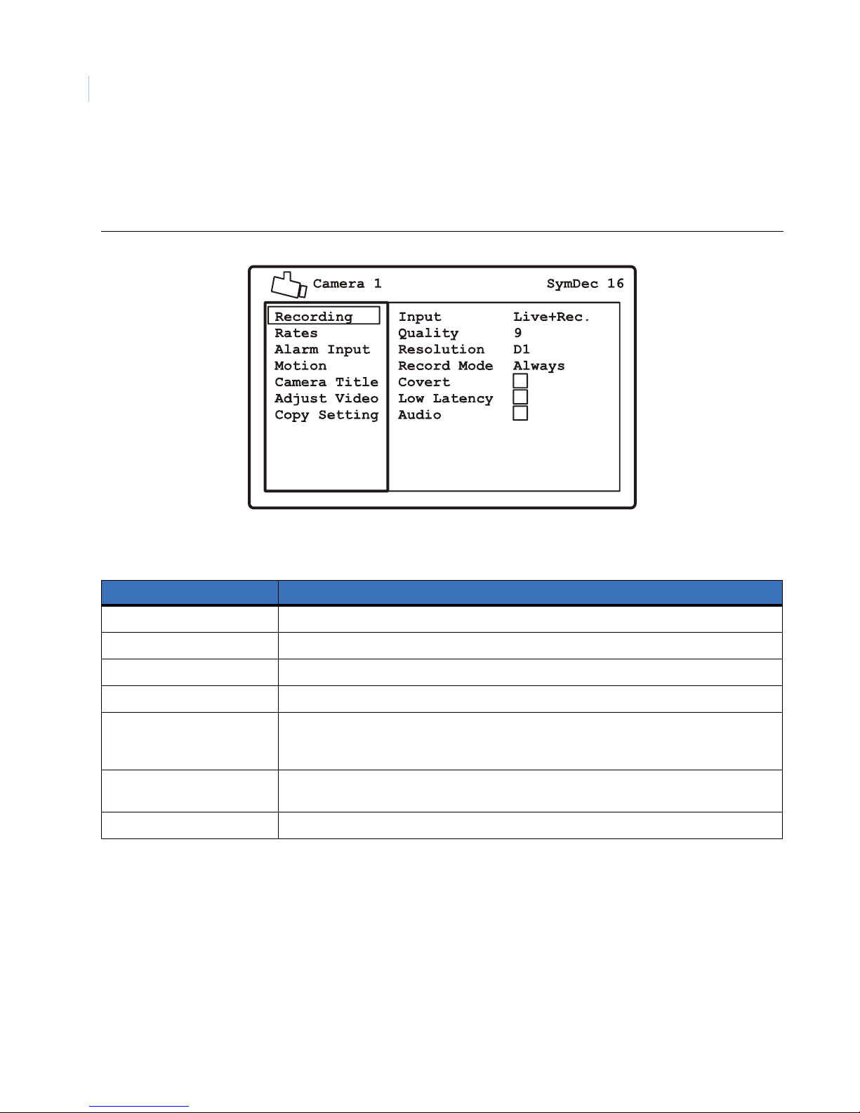
SymDec 16 plus 4
36
User Manual
Recording Menu
Use this menu to select the recording input, record quality, resolution, and record mode. You can also use this
menu to enable or disable the covert, low latency, and audio features of the camera selected.
Figure 14. The Camera/Recording menu
Table 14. Cameras/Recording options
Menu Setting Options
Record Input Live, Disable, Live + Record
Record Quality 1 (low quality) to 9 (high quality)
Resolution D1 (704x480), 2CIF (704x240), CIF (352x240)
Record Mode Always, Alarm only, Event + Alarm
Covert Enable or disable. Covert means the camera is recording but the display is turned off. After
selecting covert, you must exit and logout of the DVR menu before the changes will take
effect.
Low latency Enable or disable. Enabling low latency increases the response time but lowers the quality.
Normally used with PTZ cameras.
Audio Enable or disable audio recording on this camera. The audio option is only for Cameras 1-4.
Page 47
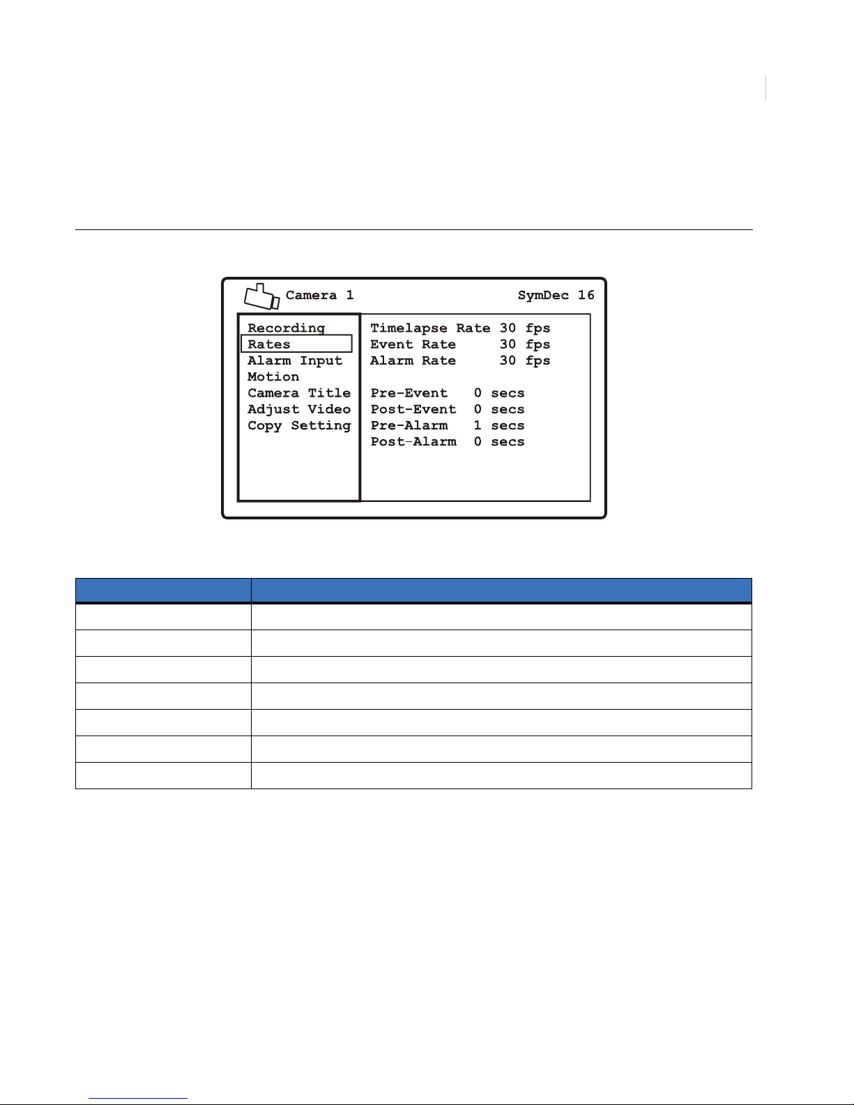
Programming the SymDec 16 plus 4
Chapter 4
Duration Rates
Use this menu to select the record rates under normal condition (timelapse rate) and when an alarm or event
occurs.You can also set the pre and post recording times for both event and alarm conditions.
Figure 15. The Camera/Duration Rates menu
37
Table 15. The Cameras/Rates options
Menu Setting Options
Timelapse Rate 2, 5, 10, 15, 30 fps (frames per second)
Event Rate 2, 5, 10, 15, 30 fps
Alarm Rate 2, 5, 10, 15, 30 fps
Pre-Event 0-99 seconds
Post-Event 0-99 seconds
Pre-Alarm 0-99 seconds
Post-Event 0-99 seconds
Note: The Pre-Event and Pre-Alarm settings are dependant on the Resolution, Quality, and Alarm Rate settings from the
Recording menu.
Page 48
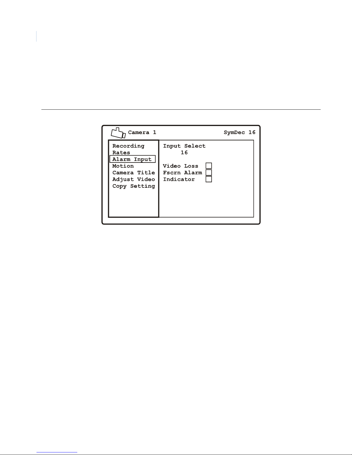
SymDec 16 plus 4
38
User Manual
Alarm Input
Use this menu to connect 1 or more alarm inputs to the currently selected camera. Press the enter button to
enter the edit mode. Select from alarm inputs 1-16 and IP alarms 1-4. You can also enable or disable video loss,
fullscreen alarm, and indicator here. When video loss is enabled it will be reported as an alarm on the selected
camera.
Figure 16. The Cameras/Alarm Inputs menu
Page 49
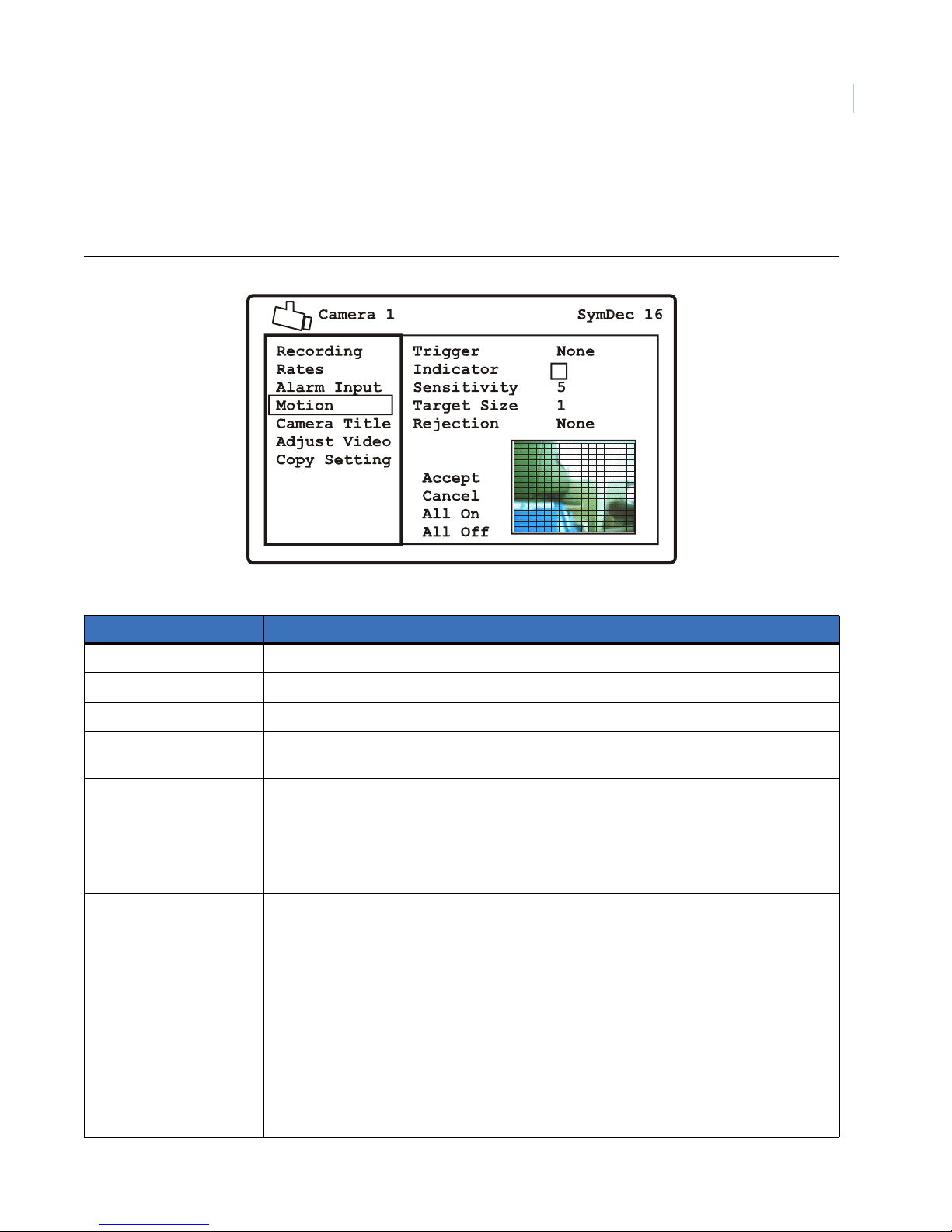
Programming the SymDec 16 plus 4
Chapter 4
Motion Detection
Use this menu to set up the various parameters associated with motion detection such as the trigger, sensitivity,
target size, rejection threshold, and where on the video to monitor for motion.
Figure 17. The Cameras/Motion Detection menu
39
Table 16. The Cameras/motion detection options
Menu setting Options
Trigger None, Event, Alarm 1-16, IP Alarm 1-4
Indicator Check to enable/disable the displaying of the M indicator.
Sensitivity 1 (least) to 9 (most)
Target size 0-256. This setting is the minimum number of zones (from the 16 x 16 grid) that must be
activated simultaneously before it is considered to be valid motion.
Rejection None, low, medium, high. These settings are based on the number of simultaneously triggered
zones and the persistence of motion in a scene. The Low setting is the most sensitive to motion.
The Medium setting will filter out most false alarm situations due to sudden luminance changes
over the whole scene (clouds passing over). The High setting will filter out sudden luminance
changes as well as spurious motion events that do not persist for a number of frames (a bird
flying past the lens).
Motion edit screen Press the enter button to move into edit mode. Use the arrow buttons to select or deselect the
areas on the gird to set for motion detection. Press the enter button to cycle through the
selection cursors:
• White outline: Use to position cursor for selection or deselection of a previously selected
area
• Blue: Selects areas on the grid for motion detection
• Red: Cursor changes to red when parameter thresholds are achieved
Press the menu button to go to the commands in the edit window. Select from:
• Accept
•Cancel
• All On
• All Off
Page 50
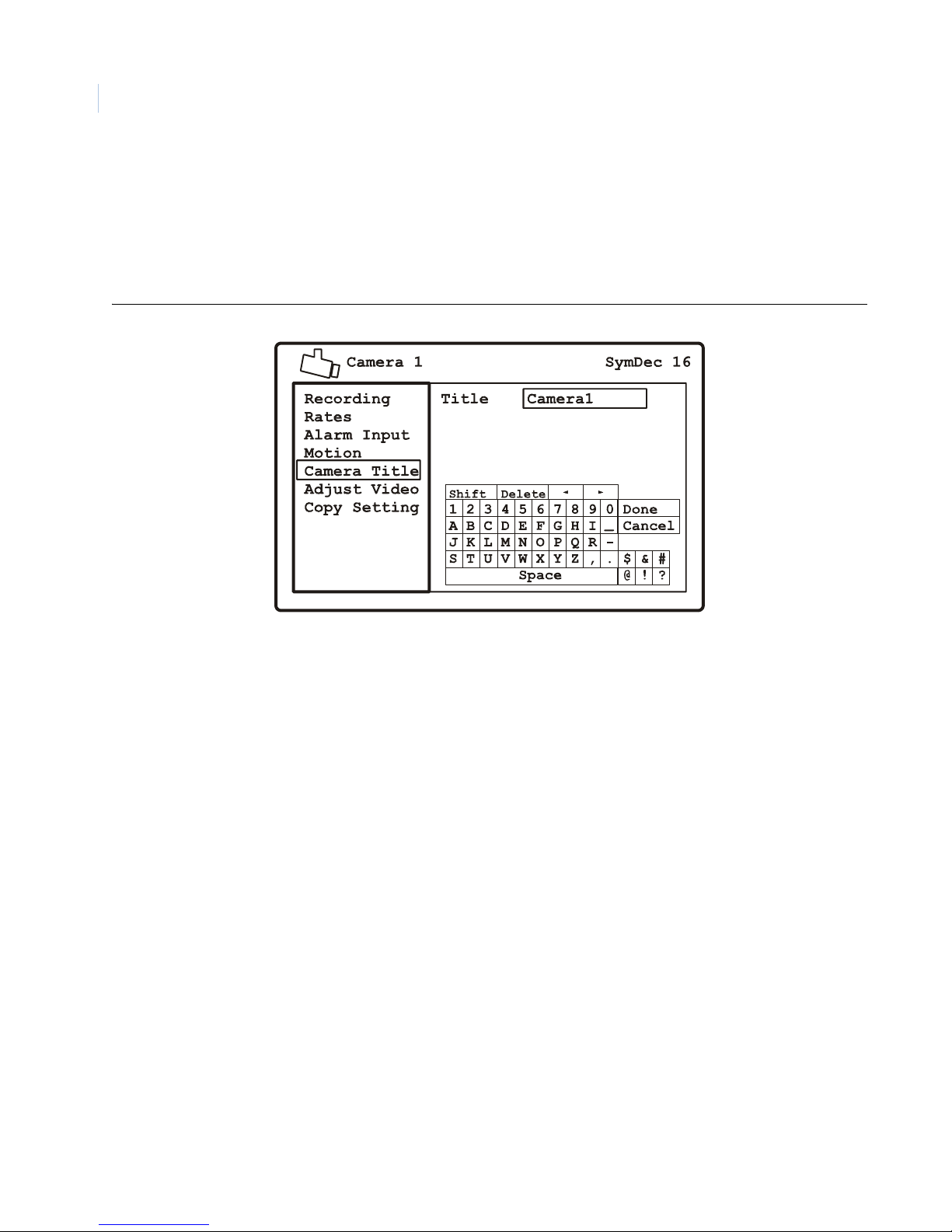
SymDec 16 plus 4
40
User Manual
Camera Title
Use this menu to change the camera title. Press the enter button to access the on-screen keypad to edit the title.
Use the arrow buttons to navigate and the enter button to select the various alphanumeric characters available.
Figure 18. The Camera/Camera Title menu
Page 51
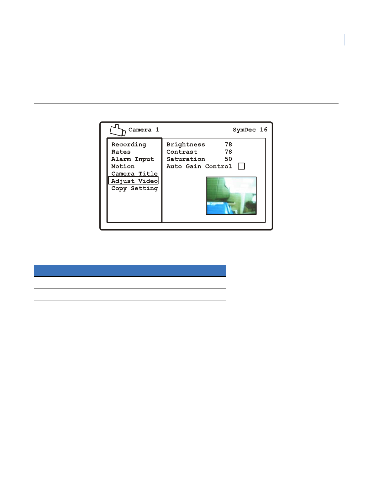
Programming the SymDec 16 plus 4
Chapter 4
Adjust Video
Use this menu to adjust the selected cameras video image. You can also enable or disable the Automatic Gain
Control (AGC) here.
Figure 19. The Camera/Adjust Video menu
41
Table 17. The Camera/Adjust Video settings
Menu setting Options
Brightness 0-99
Contrast 0-99
Saturation 0-99
Automatic Gain Control Enable/disable
Page 52
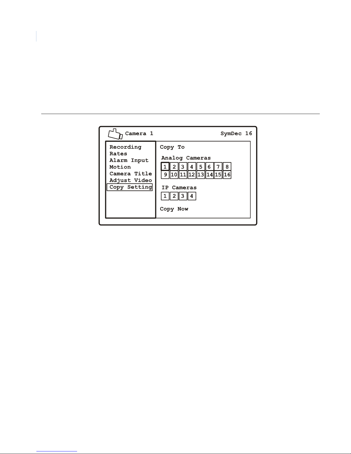
SymDec 16 plus 4
42
User Manual
Copy Settings
Use this menu to quickly copy one cameras settings to the other available cameras. Press enter to access the
edit area. Select the cameras to copy the selected camera’s parameters. Navigate to the Copy Now command to
execute.
Note: The Copy Setting command copies all the selected camera’s configurable settings.
Figure 20. The Camera/Copy Settings menu
IP Camera menu
The IP Camera menu contains the following options and their settings:
• Recording
• Rates
• Alarm Input
• Camera Title
• Copy Setting
Page 53
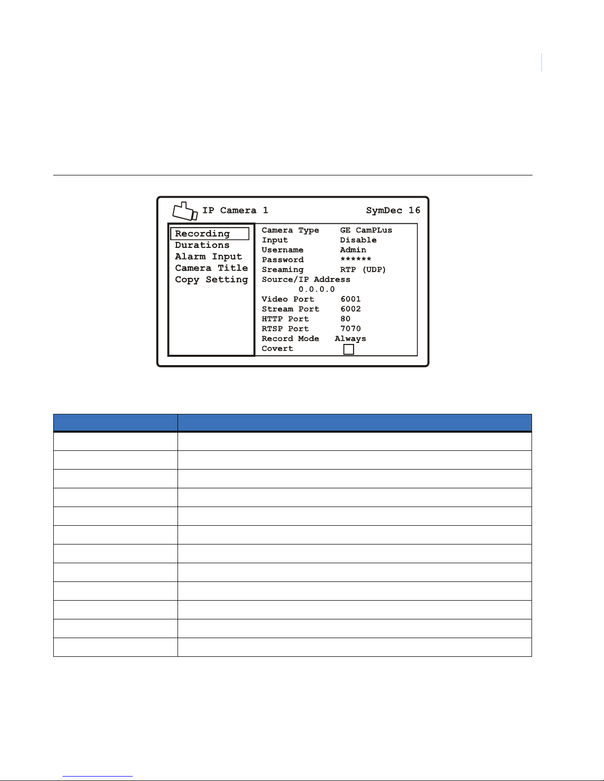
Programming the SymDec 16 plus 4
Chapter 4
Recording
Use this menu to select the camera type, recording input, IP address, and record mode of the IP camera or
video stream. You can also use this menu to enable or disable the covert feature of the IP camera selected.
These options vary according to the camera type selected.
Figure 21. The IP Camera/Recording menu
43
Table 18. Cameras/Recording options
Menu Setting Options
Camera Type SymProtcol, ACTi 2.0, GE CamPlus
Record Input Live, Disable, Live + Record
Username Press enter to launch virtual keypad to input username (not available for SymProtocol)
Password Press enter to launch virtual keypad to input password (not available for SymProtocol)
Streaming TCP Only, RTP (UDP) (not available for SymProtocol)
Source/IP Address IP address of selected camera
Video Port 6001 (not available for SymProtocol)
Stream Port 6002 (not available for SymProtocol)
HTTP Port 80 (not available for SymProtocol)
RTSP Port 7070 (not available for SymProtocol)
Record Mode Always, Alarm only, Event + Alarm
Covert Enable or disable. Covert means the camera is recording but the display is turned off.
Page 54
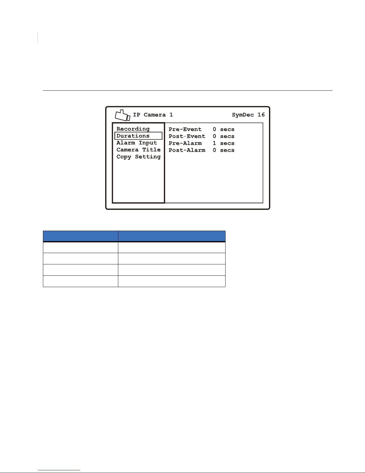
SymDec 16 plus 4
44
User Manual
Duration Rates
Use this menu to set the pre and post recording times for both event and alarm conditions.
Figure 22. The IP Camera/Duration Rates menu
Table 19. IP Cameras/Duration Rates
Menu Setting Options
Pre-Event 0-99 seconds
Post-Event 0-99 seconds
Pre-Alarm 0-99 seconds
Post-Event 0-99 seconds
Note: These settings will vary depending on the Time/Lapse settings.
Page 55
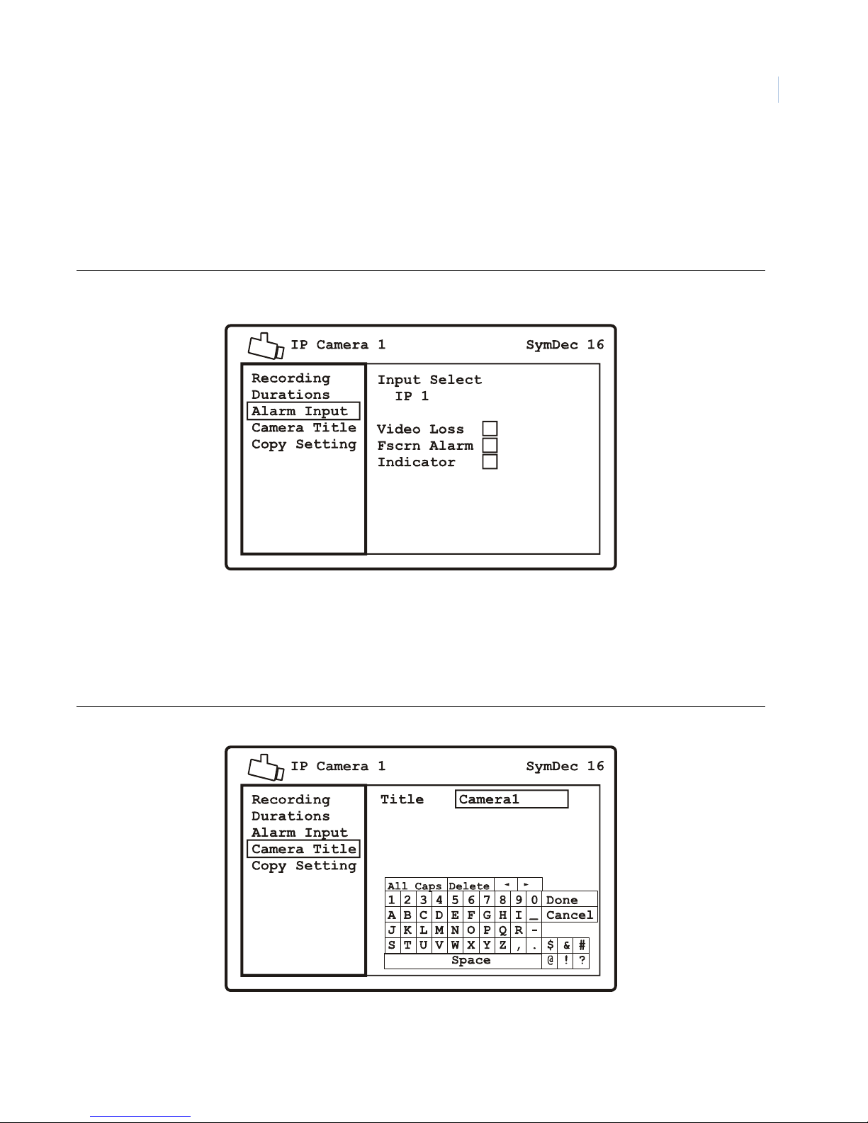
Programming the SymDec 16 plus 4
Chapter 4
IP Camera Alarm Input
Use this menu to connect 1 or more alarm inputs to the currently selected IP camera. Press the enter button to
enter the edit mode. Select from alarm inputs 1-16 and IP rearms 1-4. Y ou can also enable or disable video loss,
fullscreen alarm, and indicator here. When video loss is enabled it will be reported as an alarm on the selected
IP camera.
Figure 23. The IP Camera/Alarm Input menu
45
Camera Title
Use this menu to change the camera title. Press the enter button to access the on-screen keypad to edit the title.
Use the arrow buttons to navigate and the enter button to select the various alphanumeric characters available.
Figure 24. The IP Camera/Camera Title menu
Page 56
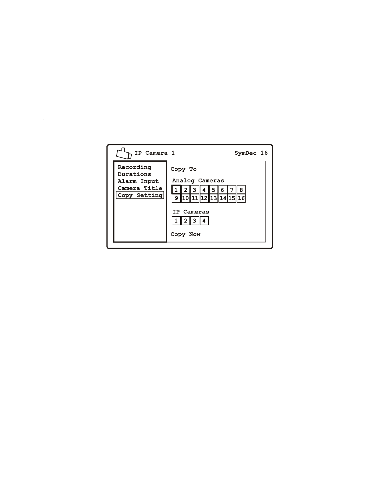
SymDec 16 plus 4
46
User Manual
Copy Settings
Use this menu to quickly copy one camera’s settings to other available cameras. Press enter to access the edit
area. Select the cameras to copy the selected camera’s parameters. Navigate to the Copy Now command to
execute.
Note: The Copy Setting command copies all the selected camera’s configurable settings.
Figure 25. The IP Camera/Copy Settings menu
Page 57
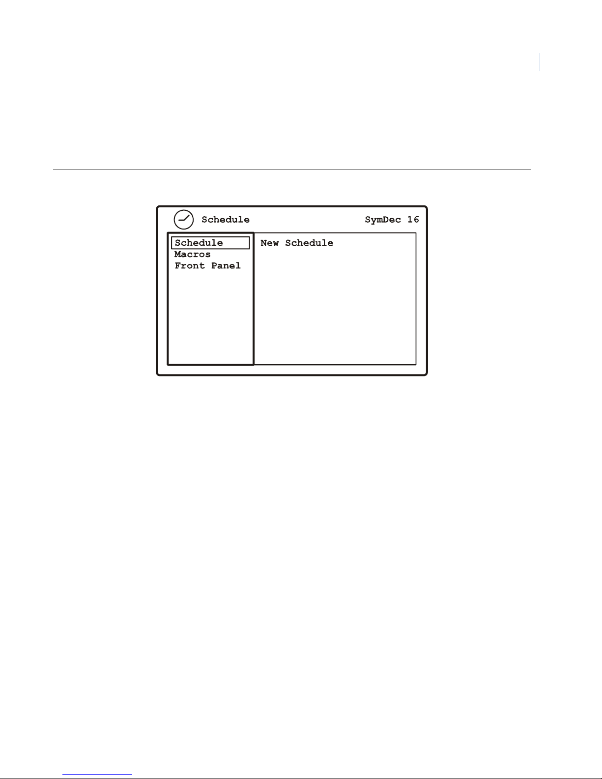
Programming the SymDec 16 plus 4
Chapter 4
The Schedule menu
Use this menu to create and schedule macros. A macro is a recorded sequence of keystrokes. Highlight the
Schedule icon and press the enter button. The Schedule menu will appear.
Figure 26. The Schedule menu
47
The Schedule menu contains the following options and their settings:
• New Schedule: Schedule start times for macros.
• Macros: Create and select macros.
• Front Panel: Assign a camera number button to a macro for front panel execution.
Page 58
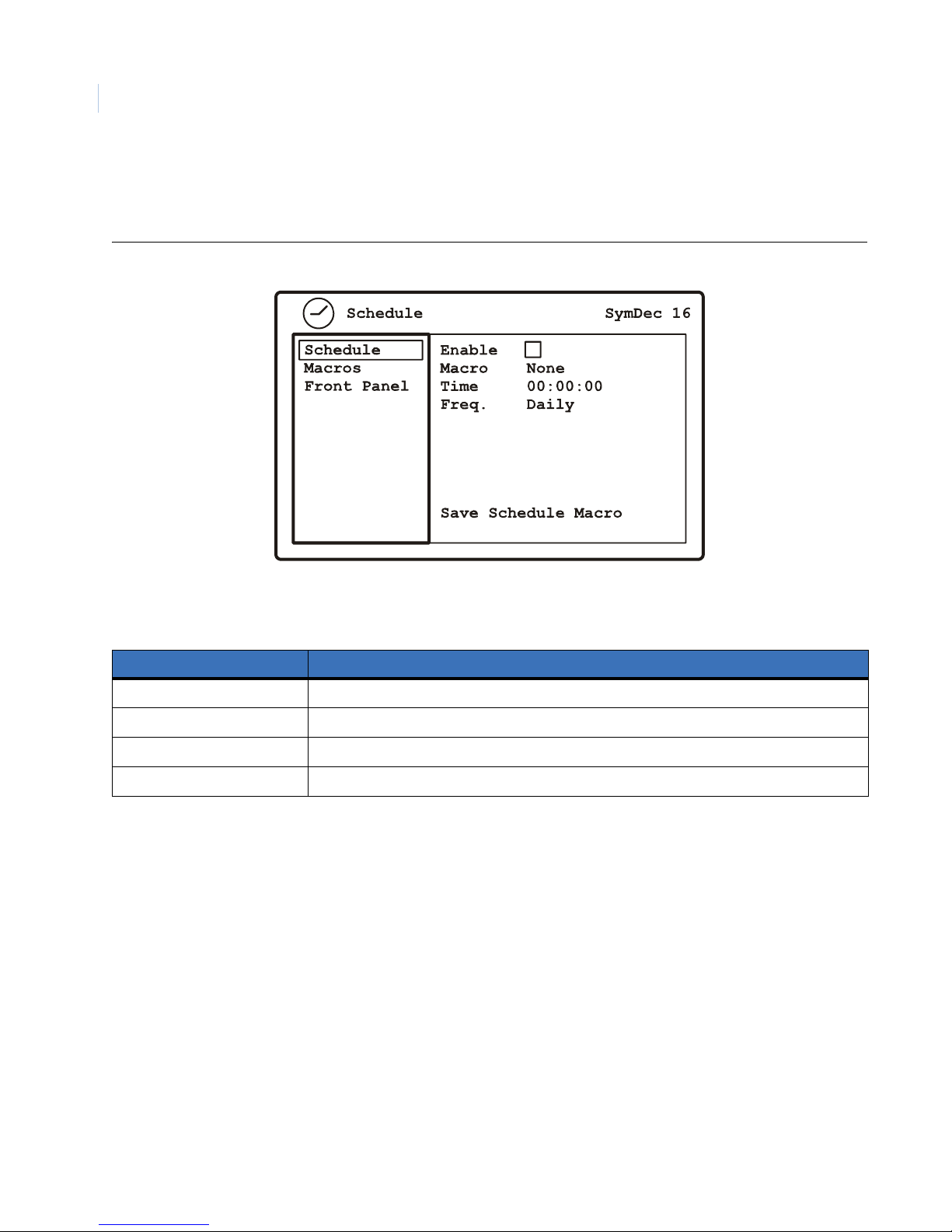
SymDec 16 plus 4
48
User Manual
New Schedule
Use this menu to create or edit a schedule for a specific macro. Press enter to access the edit area.
Figure 27. The Schedule/New Schedule menu
Table 20. The Schedule/New Schedule options
Menu Setting Options
Enable Enable or disable
Macros None or Names of defined macros
Time Define hour and minute of execution
Frequency Daily, multiple days, specific date
Page 59
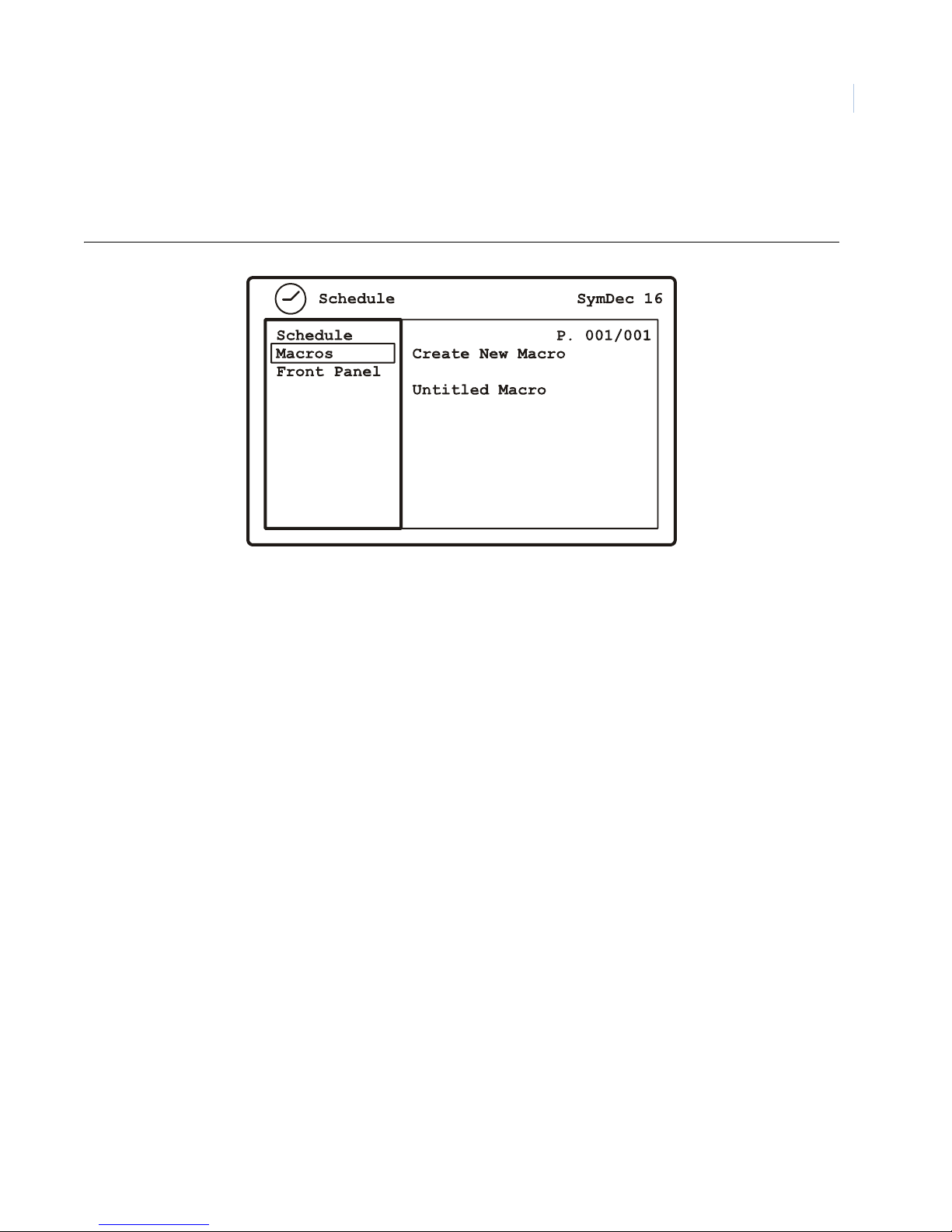
Programming the SymDec 16 plus 4
Chapter 4
Macros
Use this menu to create a new macro or edit a previously created macro.Press enter to access the edit area.
Figure 28. The Schedule/Macros Menu
49
Page 60
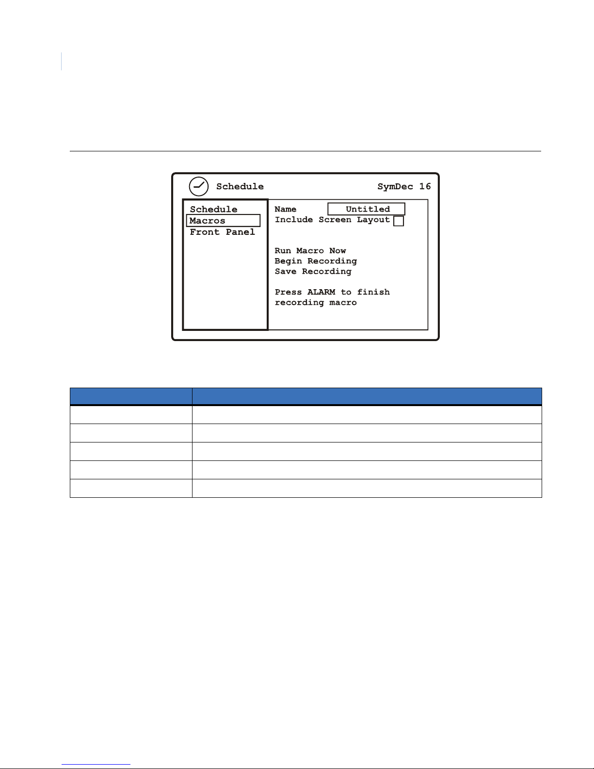
SymDec 16 plus 4
50
User Manual
Create new Macro
Use this menu to select various predefined macro features and record your macro.
Figure 29. The Schedule/Macro/Create New Macro menu
Table 21. The Schedule/Create New Macro menu options
Menu setting Options
Name Press enter to edit and use the keypad to assign a name to the macro
Include Screen Layout Check to enable/disable.
Run Macro Now Select and press enter to run the macro immediately
Begin Recording Select and press enter to start recording keystroke. Press the Alarm button to stop recording.
Save Recording Select and press enter to save the macro
Page 61
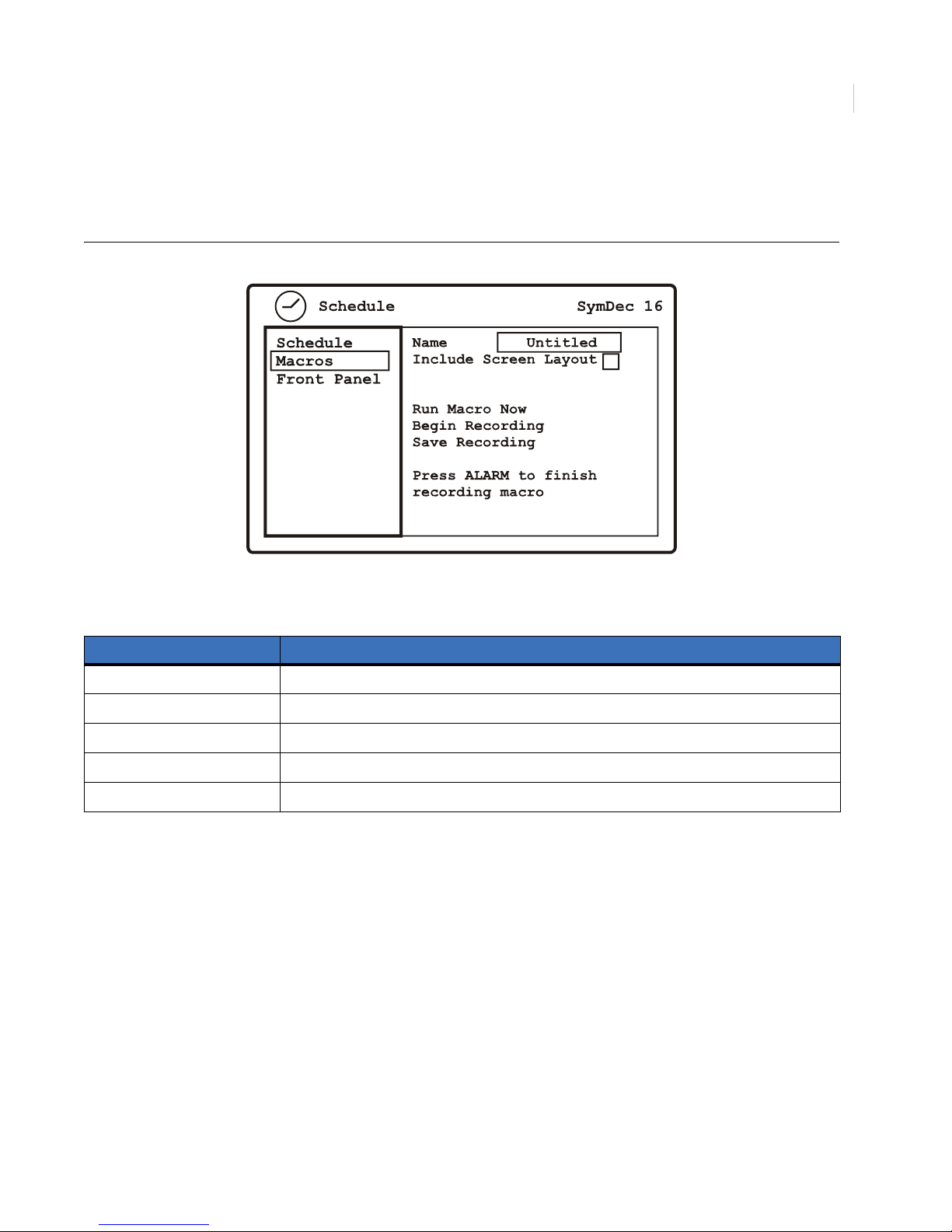
Edit Macro
Use this menu to edit previously created macros.
Figure 30. The Schedule/Macro/Edit Macro menu
Programming the SymDec 16 plus 4
Chapter 4
51
Table 22. The Schedule/Macros/Edit Macro menu options
Menu setting Options
Name Press enter to edit and use the keypad to change the name of the macro
Include Screen Layout Check to enable/disable.
Run Macro Now Select and press enter to run the macro immediately
Begin Recording Select and press enter to start recording keystroke. Press the Alarm button to stop recording.
Delete Macro Select and press enter to delete the current macro
Page 62
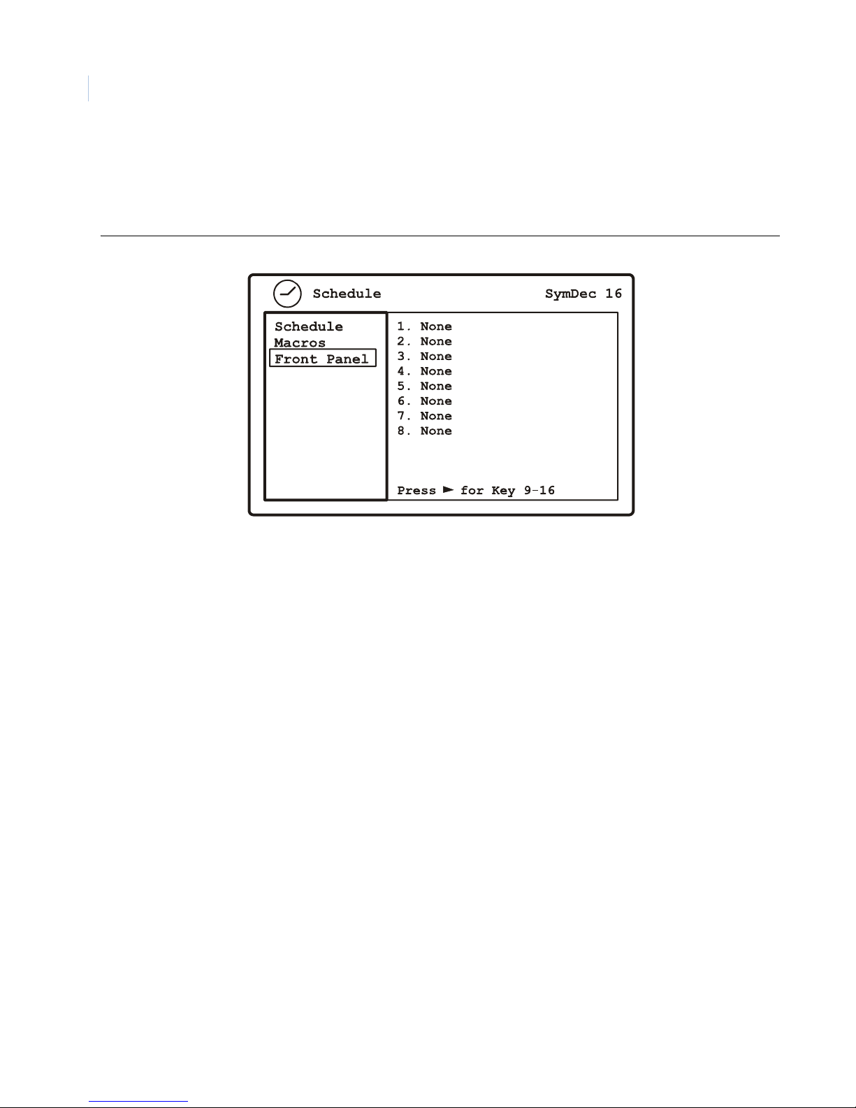
SymDec 16 plus 4
52
User Manual
Front Panel
Use this menu to assign a camera button (1-16) to a created Macro. Once assigned hold down the camera
button (2 sec.) to launch the macro.
Figure 31. The Schedule/Front Panel menu
How to schedule a macro
As an example, let’s say that we want to turn camera 1 off at 7 p.m. and back on at 7 a.m. This requires that
you:
1. Create a macro to turn camera 1 off and name it Camera 1 Off.
a. From the Macros screen press enter to move to edit mode.
b. Select Create New Macro and press enter.
c. In the Name field press enter.
d. Use the on-screen keypad to enter Camera 1 Off. Press Done when finished.
e. Navigate to Begin Recording and press enter.
f. Select Camera and press enter. Select camera 1.
g. Press enter, select Input and press enter. Select Disable and press enter.
h. Press the Alarm button to finish recording the macro.
i. Select Save Macro and press enter.
2. Create a macro to turn camera 1 on and name it Camera 1 On.
a. From the Macros screen press enter to move to edit mode.
b. Select Create New Macro and press enter.
c. In the Name field press enter.
Page 63

Programming the SymDec 16 plus 4
d. Use the on-screen keypad to enter Camera 1 On Press Done when finished.
e. Navigate to Begin Recording and press enter.
f. Select Camera and press enter. Select camera 1.
g. Press enter, select Input and press enter. Select Live + Rec. and press enter.
h. Press the Alarm button to finish recording the macro.
i. Select Save Macro and press enter.
3. Schedule macro Camera 1 Off.
a. Navigate to the Schedule menu and press enter on New Schedule to move to edit mode.
b. Press enter to enable the schedule.
c. Move the cursor to the Macro command and press enter.
d. Select Camera 1 Off and press enter.
e. Move the cursor to the Time command and press enter.
f. Use the arrow buttons to select 7 p.m. and press enter
Chapter 4
53
g. Move the cursor to the Save Schedule Macros command and press enter.
4. Schedule macro Camera 1 On.
a. Navigate to the Schedule menu and press enter on New Schedule to move to edit mode.
b. Press enter to enable the schedule.
c. Move the cursor to the Macro command and press enter.
d. Select Camera 1 On and press enter.
e. Move the cursor to the Time command and press enter.
f. Use the arrow buttons to select 7 a.m. and press enter
g. Move the cursor to the
Save Schedule Macros command and press enter.
The macros Camera 1 Off and Camera 1 On are now scheduled to run at their selected times.
Page 64
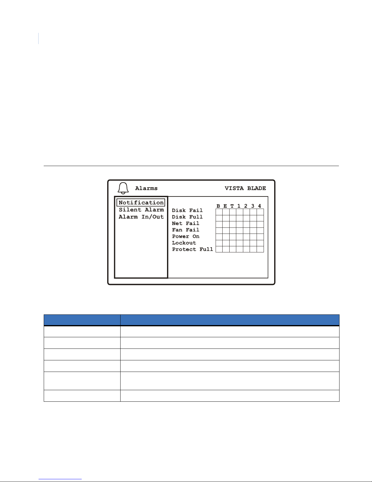
SymDec 16 plus 4
54
User Manual
The Alarms menu
Highlight the Alarm icon and press the enter button. The Alarm menu will appear. The Alarm menu contains
the following menus:
• Notification
• Silent Alarm
• Alarm Inputs and Outputs
Notification
Use this menu to assign the listed incidences to a specific output (Buzzer, Email, TCP/IP, Alarm Output 1-4).
Figure 32. The Alarms/Notification menu
Table 23. Notification descriptions
Notification Description
Disk Fail When a hard disk failure is detected.
Disk Full When a hard disk is at capacity.
Net Fail When a network failure is detected.
Fan Fail When a fan failure is detected.
Power On On shutdown a flag is set to indicate successful shutdown. If no flag is detected at bootup,
power failure is assumed.
Lockout Three repeated login failures locks the unit for 30 minutes and sends a notification.
Page 65
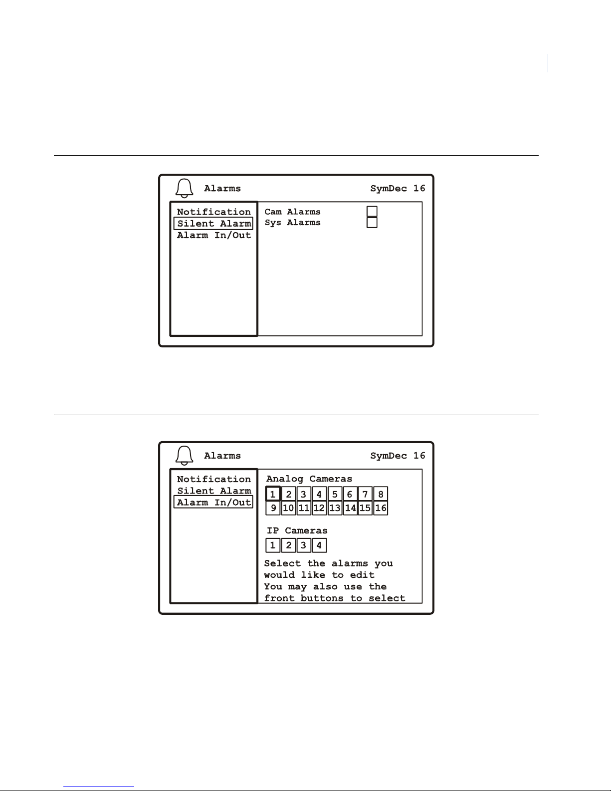
Programming the SymDec 16 plus 4
Silent Alarm
Use this menu to enable or disable an alarm (buzzer) that has been linked to Camera or Silent Alarms.
Figure 33. The Alarms/Silent Alarm menu
Chapter 4
55
Alarm Inputs and Outputs
Use this menu to attach the specified alarm inputs and outputs to the selected camera.
Figure 34. The Alarms/Alarms Inputs and Outputs menu
Note: Select Analog or IP and camera number
Page 66
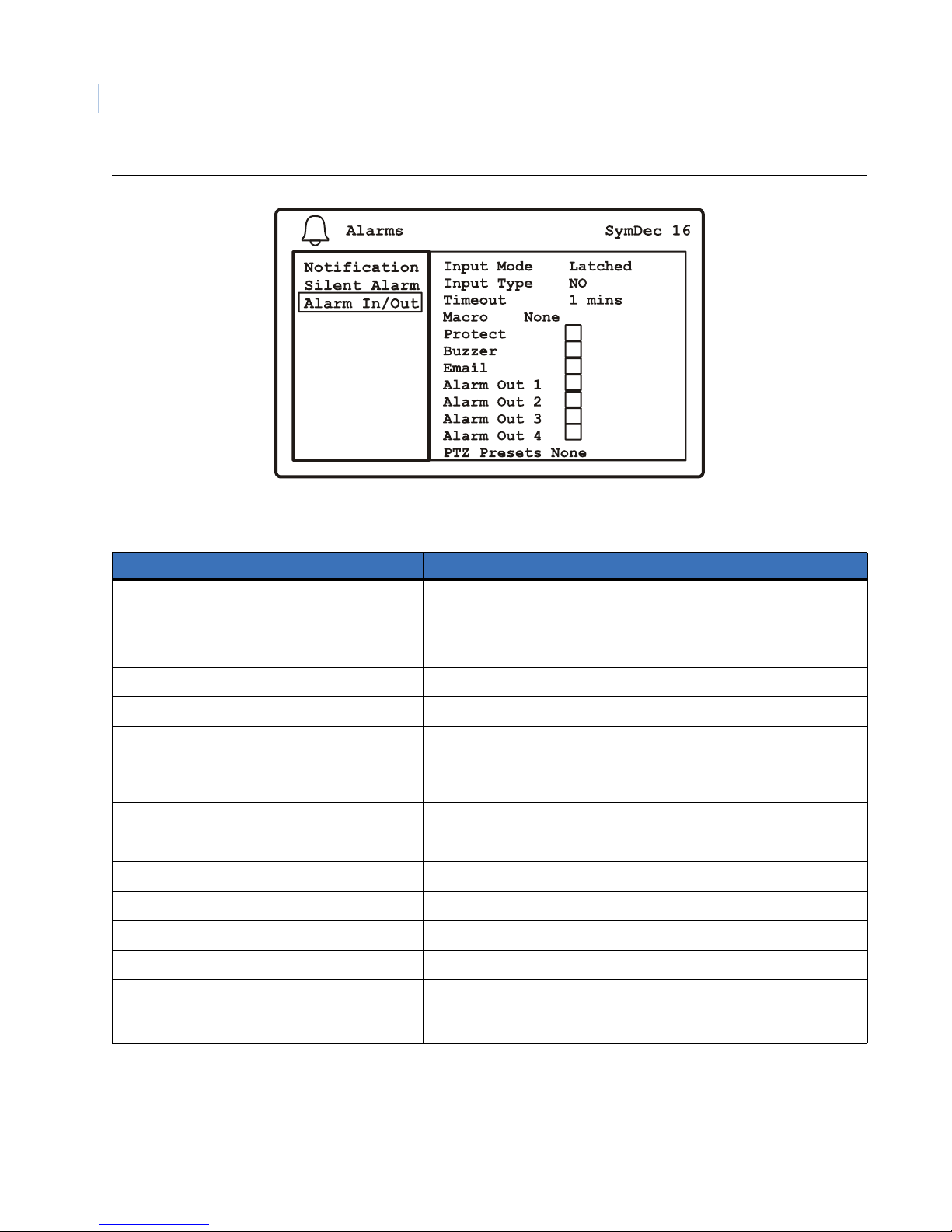
SymDec 16 plus 4
56
User Manual
Figure 35. The Alarms/Alarms Inputs and Outputs menu after camera selection
Table 24. The Alarms/Alarms Inputs and Outputs menu options
Menu Option Setting
Input Mode • Latched: The alarm is activated until it is silenced and acknowledged.
• Transparent: The alarm is active only while receiving alarm input
• Timeout: The alarm condition is latched for the amount of time
specified in the Timeout field.
Input type Normally Open, Normally Closed
Timeout 0-59 minutes if Timeout selected in Input mode
Macro None, Select Macro name (to select Macro Name you must have created
and named a macro in the Schedule/Macros menu
Protect Enable or Disable
Buzzer Enable or Disable
Email Enable or Disable
Alarm Out 1 Enable or Disable
Alarm Out 2 Enable or Disable
Alarm Out 3 Enable or Disable
Alarm Out 4 Enable or Disable
PTZ Presets Enable, Address Presets, Presets 1-4 (launches the PTZ preset submenu
where you can assign an Enable flag, Bus address, PTZ address, and
Preset number.
Page 67
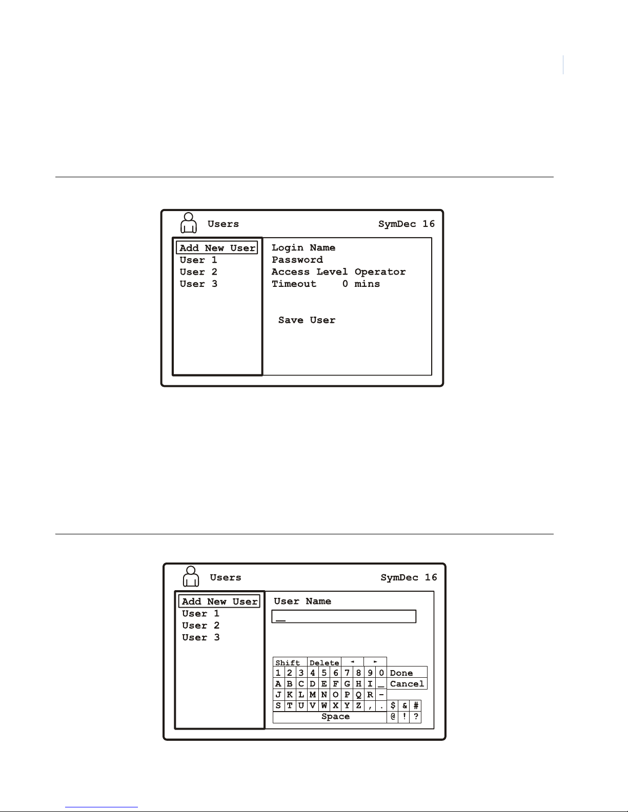
Programming the SymDec 16 plus 4
Chapter 4
The Users menu
Highlight the Users icon and press the enter button. The Users menu will appear. Up to 24 users can be logged
on to a SymDec 16 plus 4 at one time.
Figure 36. The Users menu
57
The Users menu contains the following options and their settings:
• Add New User
• Edit Users 1-3
Add New User
Use this menu to add a new user, assign a password, and select the users access level. Press enter to enter the
edit window and use the keypad to create the user’s name.
Figure 37. The Users/Add New User menu
Page 68
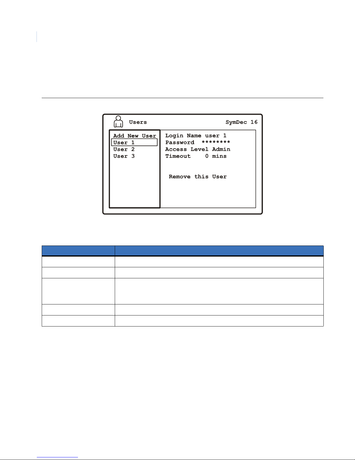
SymDec 16 plus 4
58
User Manual
Edit Users
Use this menu to edit a user’s name, password, access level, and timeout.You can also delete a user from this
menu.
Figure 38. The User/Edit User
Table 25. The User/Edit User options
Menu options Settings
Login Name Press enter to enter the edit window and use the keypad to edit the user’s name.
Password Enter from 4 to 8 characters.
Access Level • Operator: Access to Display Info menus only
• Manager: Access to Users, Display, and Info menus only
• Administrator: Full access to all menus
Timeout 0-999 minutes. At 0 minutes the unit will never timeout (log out).
Remove this User Select to delete user.
Page 69

Programming the SymDec 16 plus 4
Chapter 4
The Network menu
Highlight the Network icon and press the enter button. The Network menu will appear. The Network menu
contains the following options and their settings:
• IP Settings
• IP Advanced
•Services
•Streaming
• Passthrough
• Notification
• Email Setup
• Notification Setup
59
Page 70
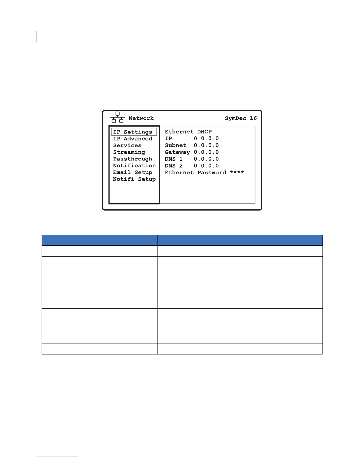
SymDec 16 plus 4
60
User Manual
IP Settings
Use this menu to setup the basic IP addresses and set the Ethernet password.
Figure 39. The Network/IP Settings menu
Table 26. The Network/IP Settings menu options
Menu options Settings
Ethernet mode Disabled, Static, DHCP, and PPPoE
IP Address Consult with a qualified network administrator or IT professional to
configure these settings if DHCP is not selected.
Subnet Mask Consult with a qualified network administrator or IT professional to
configure these settings if DHCP is not selected.
Gateway Consult with a qualified network administrator or IT professional to
configure these settings if DHCP is not selected.
Dynamic Name Server 1 Consult with a qualified network administrator or IT professional to
configure these settings if DHCP is not selected.
Dynamic Name Server 2 Consult with a qualified network administrator or IT professional to
configure these settings if DHCP is not selected.
Ethernet Password Enter 4 to 8 characters to enable.
Page 71
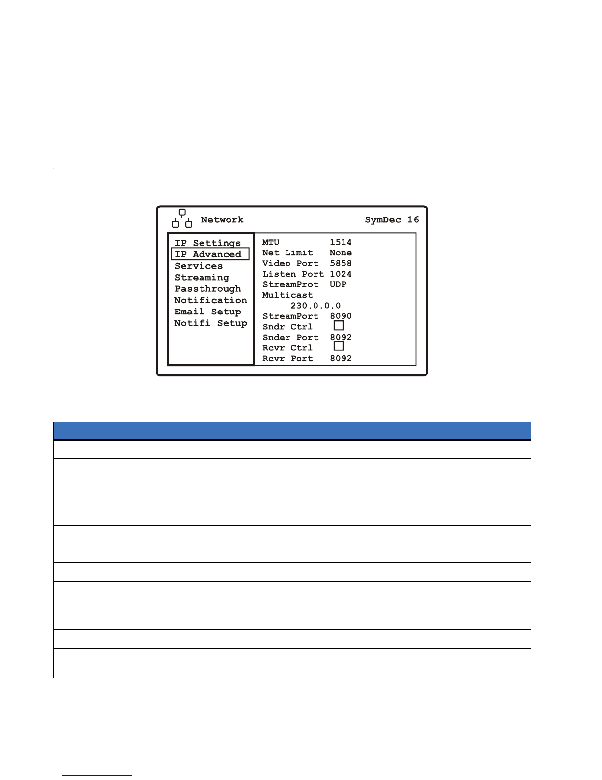
Programming the SymDec 16 plus 4
IP Advanced
Use this menu to configure these advanced network settings. Consult with a qualified network
administrator or IT professional to configure these settings.
Figure 40. The Network/IP Advanced menu
Chapter 4
61
Table 27. The Network/IP Advanced menu options
Menu Options Settings
MTU 1514 is the default. Sets the maximum TCP packet size.
Net Limit None, 0-3999 Kbps.
Video Port 5858 is the default setting.
Listen Port 1024 is the default. This is the port that the SymDec 16 uses to listen for streaming
commands
Streaming Protocol UDP, TCP
Multicast IP address 230.0.0.0. is the default . This must match between devices.
Streaming Port 8090 is the default setting for the stream.
Sender Control Enable or Disable. Must be enable to send IP video.
Sender Port 8092 is the default setting. If you change this port here make sure you also change to match
on the Receiver device.
Receiver Control Enable or Disable. Must be enabled to receive IP video.
Receiver Port 8092 is the default setting. If you change this port here make sure you also change to match
on the Sender device.
Page 72

SymDec 16 plus 4
62
User Manual
Muticast Video Streaming Overview
Video streaming is a new concept to many, so we have included the following overview. A certain level of IP
network knowledge is required to properly set up video streamin g
Video Streaming is the process that the SymDec family, including SymNet and the Symveo IP camera use to
listen on a specific UDP/TCP port for control messages and respond to them. The communication over this
protocol can be between a PC application, such as SymNav software and any of the above products. The UDP/
TCP port is configurable. The default port setting is 8092. IP Multicast is also supported.
IP Multicast
IP multicast is a bandwidth-conserving technology that reduces traffic by simultaneously delivering a single
stream of information to thousands of recipients. IP Multicast delivers source traffic to multiple receivers
without adding any additional burden on the source or the receivers while using the least network bandwidth of
any competing technology. High-bandwidth applications, such as MPEG video, may require a large portion of
the available network bandwidth for a single stream.
Note: Configured incorrectly IP multicast can become a serious drain on your networks resources! If you are at all uncertain
on how to setup IP multicast , please contact your network administrator or IS professional.
The Internet Assigned Numbers Authority (IANA) controls the assignment of IP multicast addresses. It has
assigned the Class D address space to be used for IP multicast. This means that all IP multicast group addresses
will fall in the range of 224.0.0.0 to 239.255.255.255. This address range is only used for the group address or
destination address of IP multicast traffic. The source address for multicast video is always the source or
senders IP address.
UDP Sender and UDP Receiver Overview
UDP (User Datagram Protocol), is a connectionless protocol that, like TCP , runs on top of IP networks. Unlike
TCP/IP, UDP/IP provides very few error recovery services, offering instead a direct way to send and receive
datagrams over an IP network. It's used primarily for broadcasting messages over a network. A UDP sender
sends out digital video over an IP network. A UDP sender can be the SymDec 4, SymDec 16 plus 4, Symveo
IP Camera, or SymNet (Encoder). A UDP receiver is typically a SymDec 16, SymNav software, or a SymDec
4, which can display and record the streamed video. The SymNet (Decoder) can also be setup as a receiver, but
it can only display the streamed video since it does not have recording capability.
To prevent a waste of network resources, the UDP sender does not send out streaming video until a receiver
informs the sender that it is interested in receiving the stream. The UDP receiver sends out a START message
every 30 seconds to the IP address in its streaming settings menu. The streaming settings page is located on the
receiving device's web page.
When a sender receives a START message, it will start streaming out to the receiver's that are requesting it.
When the sender does not receive any START message for one minute, it will stop sending to that device.
To speed up the initialization process after bootup and configuration changes, The UDP sender sends out a
READY_TO_SEND message to the multicast IP address. When the receiver gets this message, it will send out
the START message immediately if it is configured to receive from that sender (It does not wait for 30 seconds).
Note: The above information also applies if your Sender and Receiver are configured to use TCP instead of UDP.
Page 73
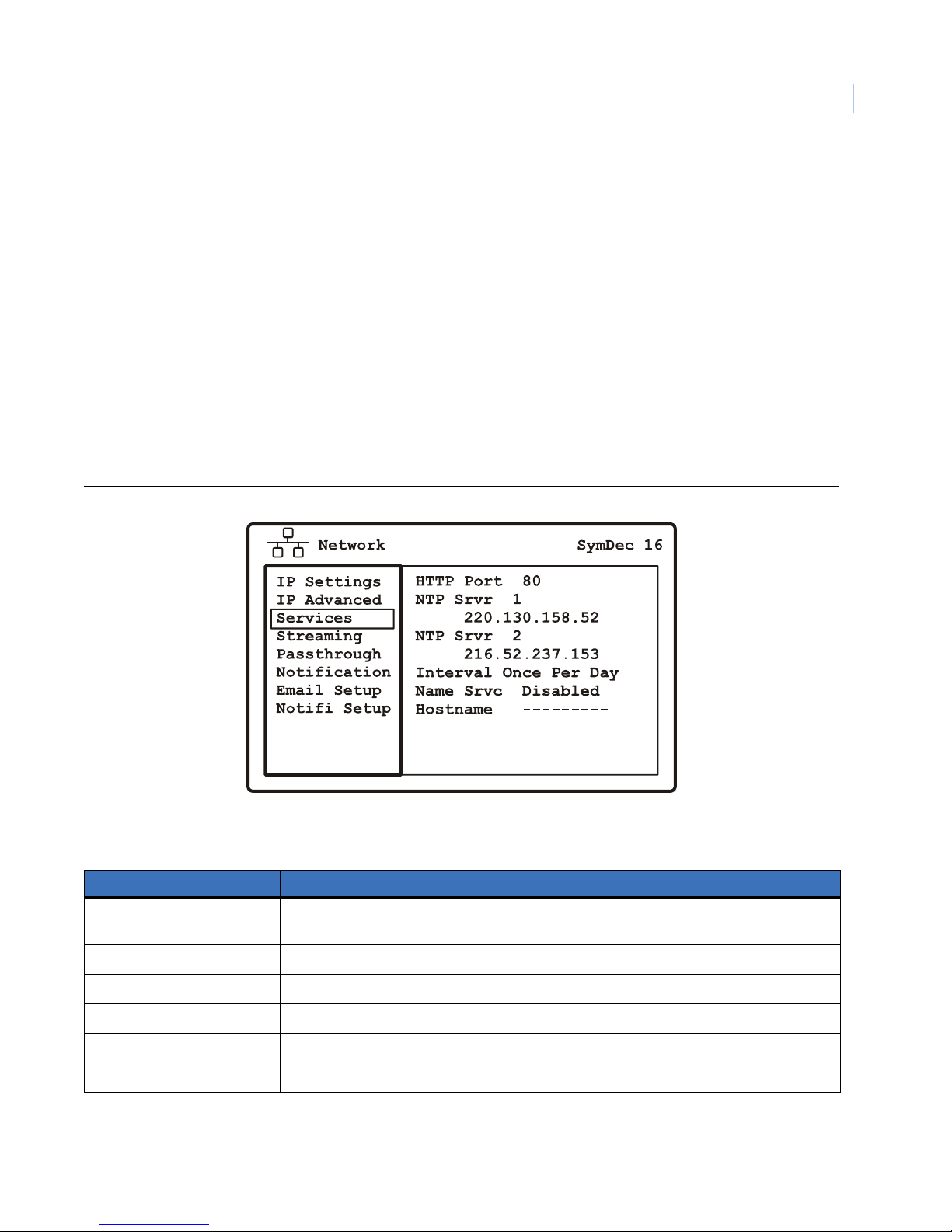
Programming the SymDec 16 plus 4
Chapter 4
SymNav software
SymNav software is the next generation of software that supports MPEG4 based video compression. The
SymDec 4, SymDec 16 plus, SymNet, and SymVeo IP Camera all use MPEG4 compression.
SymNav software also connects to these products using UDP/TCP protocols depending on what is configured.
The default setting is UDP. Changing from UDP to TCP or TCP to UDP is accomplished through the SymNav
software application.
SymNav software can connect to a maximum of 4 video streams. This can be 4 separate SymDec units with 1
stream each or 2 SymDecs with 2 streams each.
Services
Use this menu to define the parameters of the networks services.Consult with a qualified network
administrator or IT professional to configure these settings
Figure 41. The Network/Services menu
63
Table 28. The Network/Services menu options
Menu Options Settings
HTTP Port 80 is the default. Select from 0 to 65535. To disable SymBrowser access select 0 as the port
number.
NTP Server 1 IP Address IP Address
NTP Server 2 IP Address IP address
Interval Never, Once per Hour, Twice per Day, Once per Day
Name Service Disabled, DynDNS, TZO, GnuDIP
Hostname The default hostname is the unit’s serial number.
Page 74
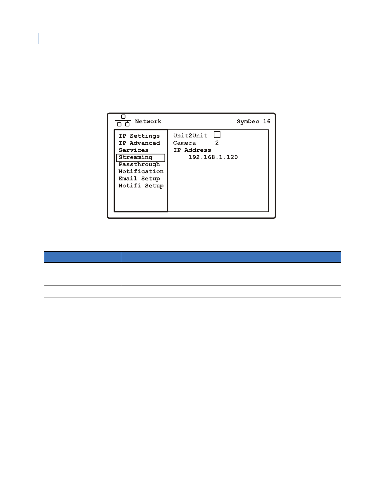
SymDec 16 plus 4
64
User Manual
Streaming
Use this menu to enable streaming output on an IP camera.
Figure 42. The Network/Streaming menu
Table 29. The Network/Streaming menu options
Menu Options Settings
Unit 2 Unit Enable or Disable streaming
Camera 1 to 16
IP Address Select the IP address of the camera
To receive unicast video from another unit
1. Go to Cameras/IP Camera 1. Set the source address to the physical address of the unit sending a
unicast video stream. You can repeat this for IP Cameras 2 to 4.
To receive multicast video from different units
1. Navigate to the Network/IP Advanced/Multicast setting. Set the Multicast address of the stream you
are going to receive to 230.123.456.789.
Note: Note that if there are four units sending multicast streams, each unit must have the same multicast stream
address.
2. Navigate to Cameras/IP Camera 1. Set the source address to the physical address of the unit sending a
multicast video stream. You can repeat this for IP Cameras 2 to 4.
Page 75
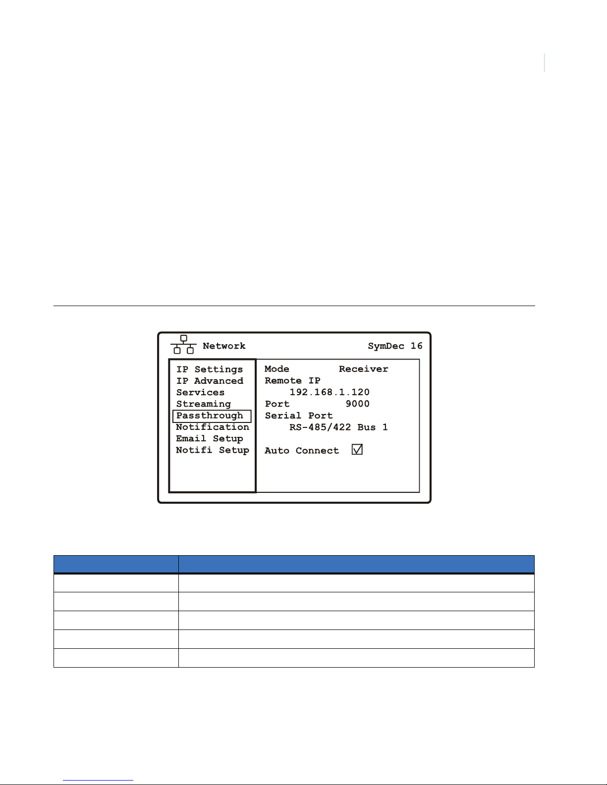
Programming the SymDec 16 plus 4
Chapter 4
Serial Passthrough
Use this menu to select the serial passthrough mode, remote IP address, port number, serial port type, and
autoconnect enable/disable.
Serial pass-through functionality is for receiving or sending serial commands such as PTZ commands over the
Internet.To setup serial pass-three;
1. Set the Mode to Sender or to Receiver. This is for the SymDec 16 plus 4 to either send or receive data.
2. Select he Remote IP and the Port number of the unit you want to send/receive serial pass-through data.
Both units must have the same port number.
3. The Serial Port option specifies which port you want to send/receive serial data.
4. Make sure that the Auto-Connect checkbox is checked as it maintains the serial port as active.
Figure 43. The Network/Serial Passthrough menu
65
Table 30. The Network/Serial Passthrough menu options
Menu Options Settings
Mode Receiver or Sender
Remote IP Enter the IP address of the remote device
Port 9000
Serial Port RS-485/422 Bus 1, RS-485/422 Bus 2, None
Auto Connect Enable or Disable
Page 76
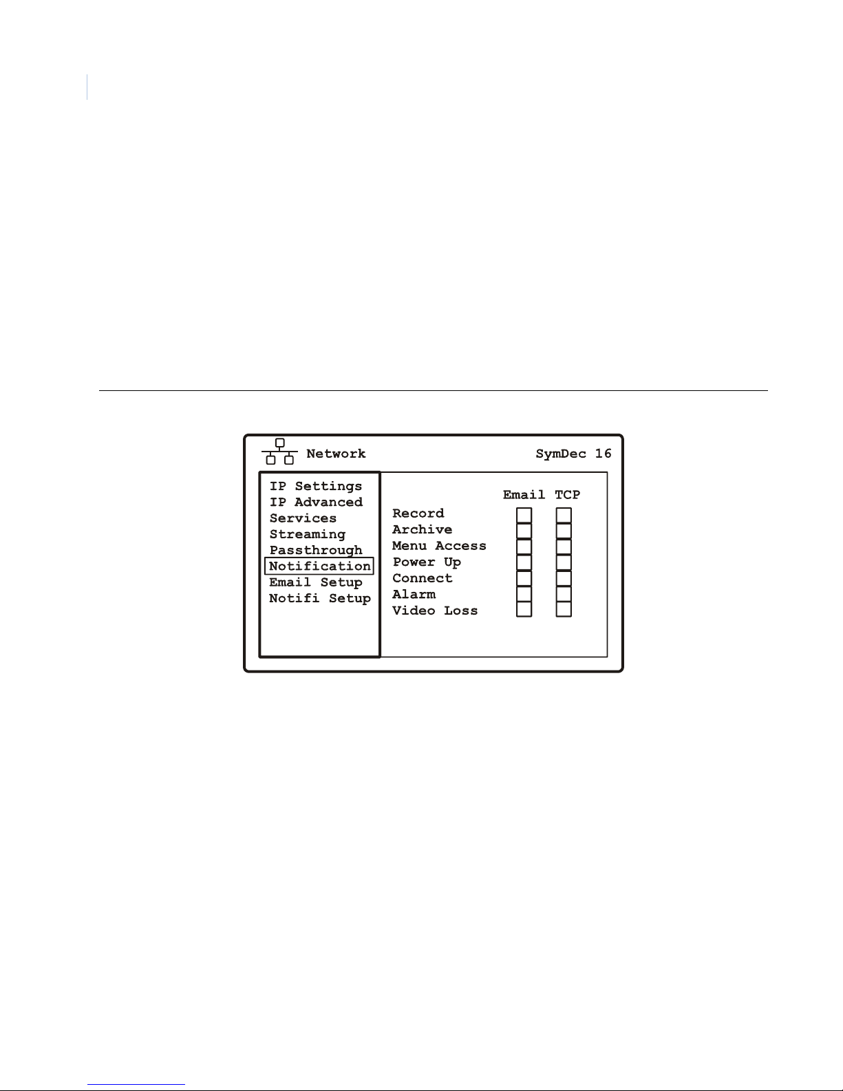
SymDec 16 plus 4
66
User Manual
Email/TCP Notification
Use this menu to select the method of notification (email or TCP) for the following incidents:
• Notify on Record
• Notify on Archive
• Notify on Menu Access
• Notify on Power Up
• Notify on Connection
• Notify on Alarm
• Notify on Video Loss
Select a checkmark in either box to enable.
Figure 44. The Network/Notification menu
Page 77
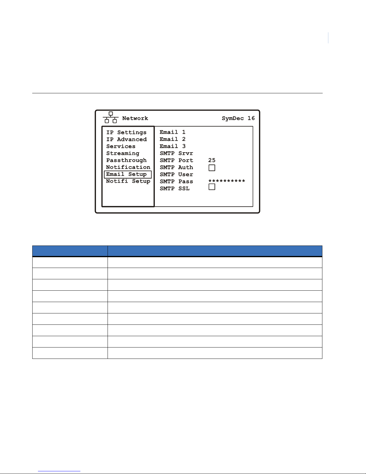
Email Setup
Use this menu to setup the email locations where notifications will be sent.
Figure 45. The Network/Email Setup menu
Programming the SymDec 16 plus 4
Chapter 4
67
Table 31. The Network/Email Setup menu options
Menu Options Settings
Email 1 Ist email address
Email 2 2nd E-mail address
Email 3 3rd email address
SMTP Server Enter a valid Simple Mail Transfer Protocol (SMTP) name
SMTP Port Default is 25
SMTP Authorization Check to enable or disable
SMTP User Enter a valid SMTP username
SMTP Password 1 to 10 characters
SMTP SSL Enable or disable SSL (Secure Sockets Layer) encryption
Page 78
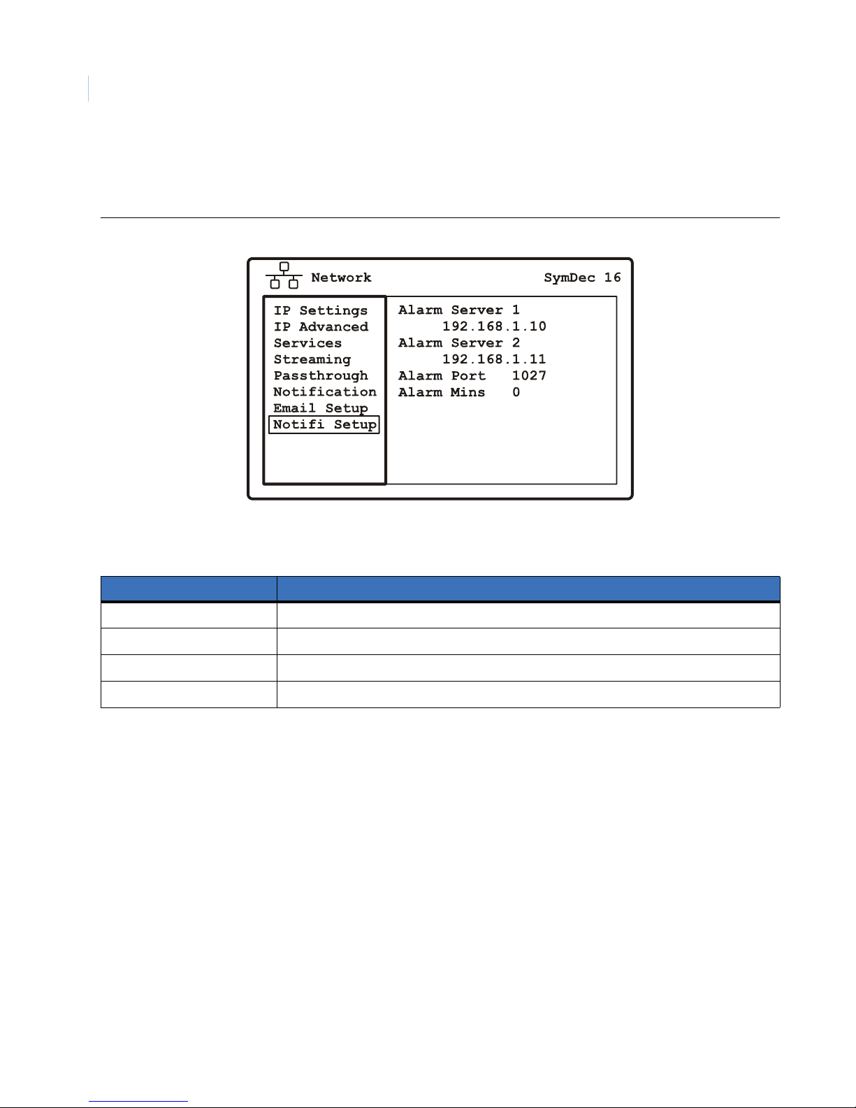
SymDec 16 plus 4
68
User Manual
Notification Setup
Use this menu to setup the TCP/IP addresses where notification is to be sent.
Figure 46. The Network/Notification Setup menu
Table 32. The Network/Notification Setup menu options
Menu Options Settings
Alarm Server 1 Enter a primary alarm server IP address
Alarm Server 2 Enter a backup alarm server IP address
Alarm port Default is 1027. Choose from 1024 to 32767.
Alarm Minutes 0 to 299. Minutes after the event to send notification
Page 79
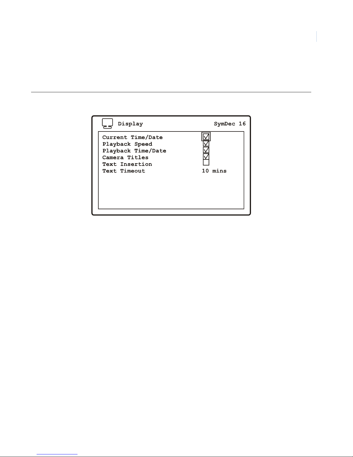
Programming the SymDec 16 plus 4
The Display menu
Highlight the Display icon and press the enter button. The Display menu will appear.
Figure 47. The Display menu
Chapter 4
69
The Display menu contains the following options and their settings:
•Current Time/Date
• Playback Speed
• Playback Time/Date
• Camera Titles
• Text Insertion: Inserts serial -based text.
• Text Timeout: 0-99 minutes (the length of time the text is displayed in minutes)
Enter a checkmark in the box to enable.
Page 80
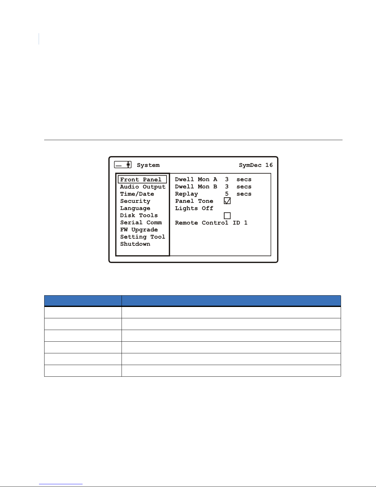
SymDec 16 plus 4
70
User Manual
The System menu
Highlight the System icon and press the enter button. The System menu will appear.The System menu contains
the following options and their settings:
Front Panel
Use this menu to setup the front panel features. The remote control ID setup is also configured here.
Figure 48. The System/Front Panel menu
Table 33. The System/Front Panel menu options
Menu Options Settings
Dwell Monitor A 0-99 seconds
Dwell Monitor B 0-99 seconds
Replay 0-999 seconds
Panel Tone Enable or disable
Lights Off Enable or disable
Remote Control ID Select from disable, and 1 to 4
Page 81
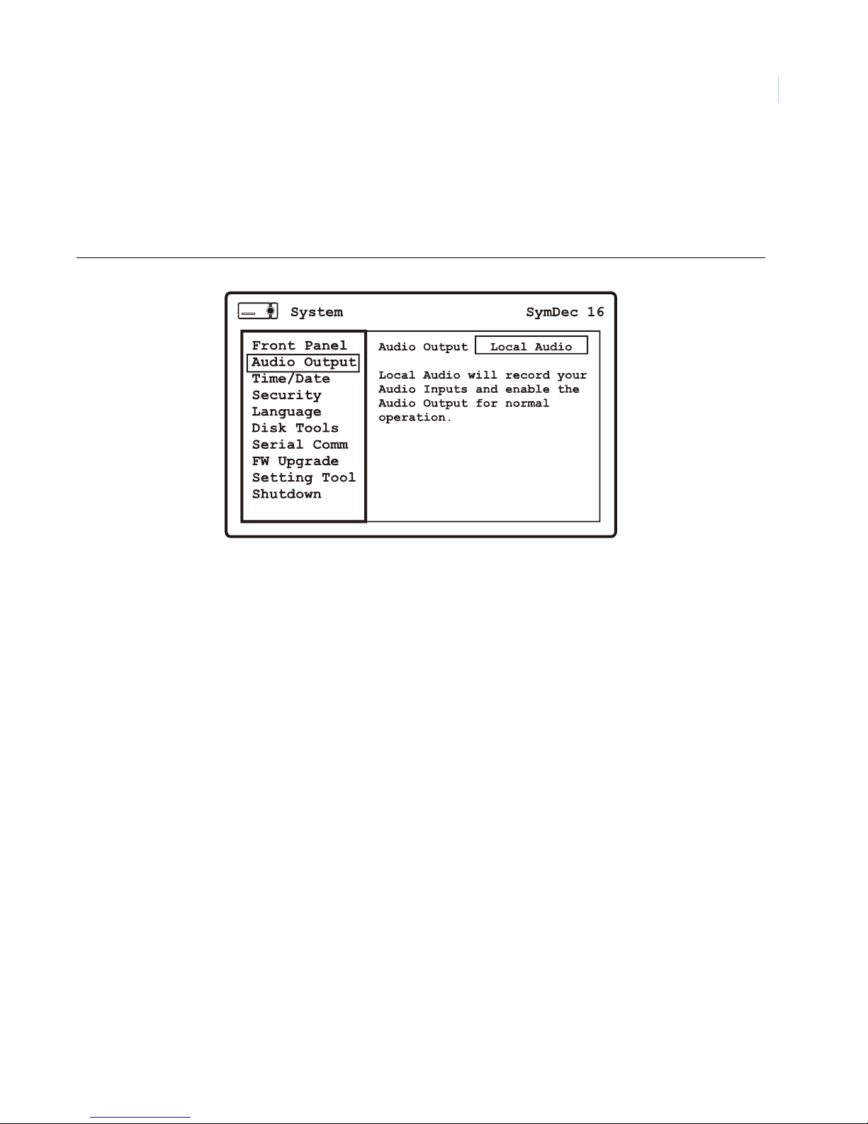
Programming the SymDec 16 plus 4
Chapter 4
Audio Output
This menus allows you to select local or remote audio.Local audio is audio received from the audio inputs on
the SymDec 16 and recorded with the video. Remote audio is audio received for a PC client and is not
recorded, but passed through to the audio output.
Figure 49. System/Audio Output menu
71
Page 82
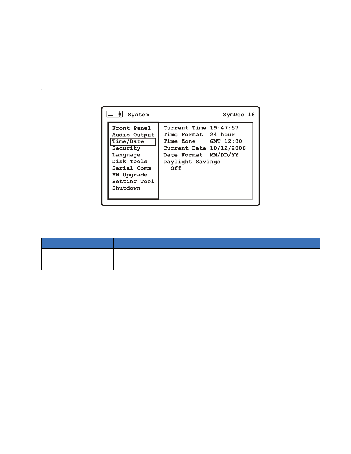
SymDec 16 plus 4
72
User Manual
Time/Date
Use this menu to setup the time and date features of the SymDec 16 plus 4.
Figure 50. The System/Time and Date menu
Table 34. The System/Time and Date menu options
Menu Options Settings
Current Time Press the enter button when selected to enter the time.
Time Format 12 or 24
Page 83

Programming the SymDec 16 plus 4
Table 34. The System/Time and Date menu options
Menu Options Settings
Time Zone • GMT: Casablanca, Monrovia, Dublin, Edinburgh, Lisbon, London
• GMT-01:00: Azores, Cape Verde Is.
• GMT-02:00: Mid-Atlantic
• GMT-03:00: Brasilia, Buenos Aires, Georgetown, Greenland
• GMT-03:30: Newfoundland
• GMT-04:00: Atlantic Time (Canada), Caracas, La Paz, Santiago
• GMT-05:00: Bogata, Lima, Quito, Eastern Time (US & Canada), Indiana (East)
• GMT-06:00: Central America, Central Time (US & Canada), Mexico City, Saskatchewan
• GMT-07:00: Arizona, Mountain Time (US & Canada)
• GMT-08:00: Pacific Time (US & Canada), Tijuana
• GMT-09:00: Alaska
• GMT-10:00: Hawaii
• GMT-11:00: Midway Island, Samoa
• GMT-12:00: Eniwetok, Kwajalein
• GMT+01:00: Amsterdam, Berlin, Bern, Rome, Stockholm, Vienna, Belgrade, Bratislava,
Budapest, Ljubljana, Prague, Brussels, Copenhagen, Madrid, Paris, Sarajevo, Skopje,
Sofija, Vilnius, Warsaw, Zagreb, West Central Africa
• GMT+02:00: Athens, Istanbul, Minsk, Bucharest , Cairo, Harare, Pretoria, Helsinki, Riga,
Tallinn, Jerusalem
• GMT+03:00: Baghdad, Kuwait, Riyadh, Moscow, St. Petersburg, Volgograd, Nairobi
• GMT+03:30: Tehran
• GMT+04:00: Abu Dhabi, Muscat, Baku, Tbilisi, Yerevan
• GMT+04:30: Kabul
• GMT+05:00: Ekaterinburg, Islamabad, Karachi, Tashkent
• GMT+05:30: Calcutta, Chennai, Mumbai, New Delhi
• GMT+05:45: Kathmandu
• GMT+06:00: Almaty, Novosibirsk, Astana, Dhaka, Sri Jayawardenepura
• GMT+06:30: Rangoon
• GMT+07:00: Bankok, Hanoi, Jakarta, Krasnoyarsk
• GMT+08:00: Beijing, Chongqing, Hong Kong, Urumqi, Irkutsk, Ulaan Bataar, Kuala Lampur,
Singapore, Perth, Taipei
• GMT+09:00: Osaka, Sapporo, Tokyo, Seoul, Yakutsk
• GMT+09:30: Adelaide, Darwin
• GMT+10:00: Brisbane, Canberra, Melbourne, Sydney, Guam, Port Moresby, Hobart,
Vladivosstok
• GMT+11:00: Magadan, Solomon Is, New Caledonia
Chapter 4
73
Current Date Press the enter button when selected to enter the date
Date Format MM/DD/YYYY or YYYY/MM/DD
Daylight Savings T ime Select Off, U.S.A., North America, Europe, Australia, New Zealand, or Russia
Note: North America is DST times from 2006, USA is set for the newly proposed dates in 2007.
Page 84
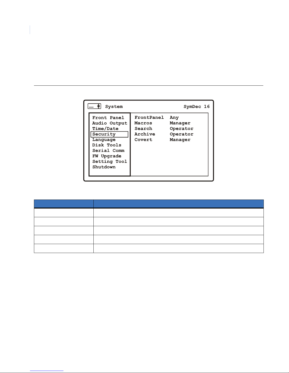
SymDec 16 plus 4
74
User Manual
Security
Use this menu to setup the security features of the SymDec 16 plus 4. This menu allows you to select the user
type (Administrator, Operator, Manager) to allow access to these features. Selecting Any allows any user type
access to modify these security operations.
Figure 51. The System/Security menu
Table 35. The System/Security men options
Menu Options Settings
Front Panel Any, Administrator, Operator, Manager
Macros Any, Administrator, Operator, Manager
Search Any, Administrator, Operator, Manager
Archive Any, Administrator, Operator, Manager
Covert Any, Administrator, Operator, Manager
Page 85
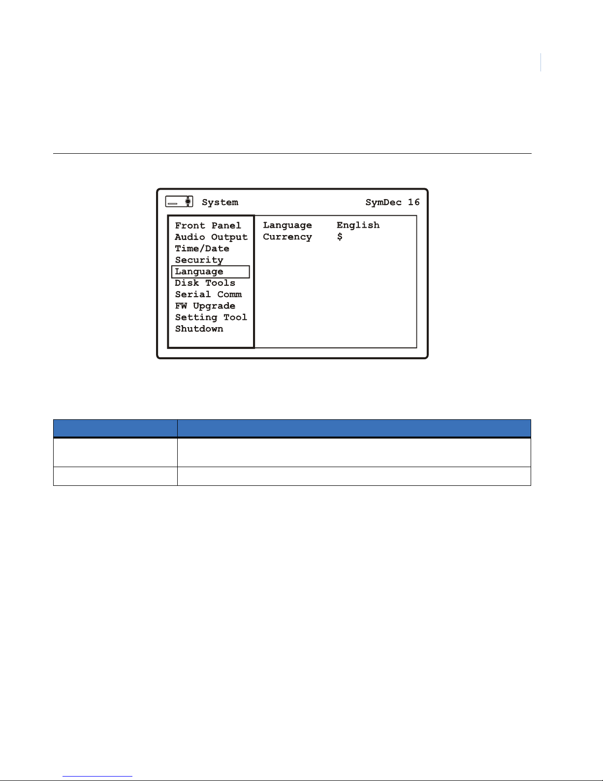
Languages
Use this menu to setup the language and currency usage
Figure 52. The System/Language menu
Programming the SymDec 16 plus 4
Chapter 4
75
Table 36. The System/Language men options
Menu Options Settings
Language English, Turkish. Swedish, Spanish, Russian, Portuguese, Polish, Italian, Hungarian, German,
Finnish, Dutch, Danish, Czech, French
Currency $ (Select currency type for text insertion purposes)
Page 86
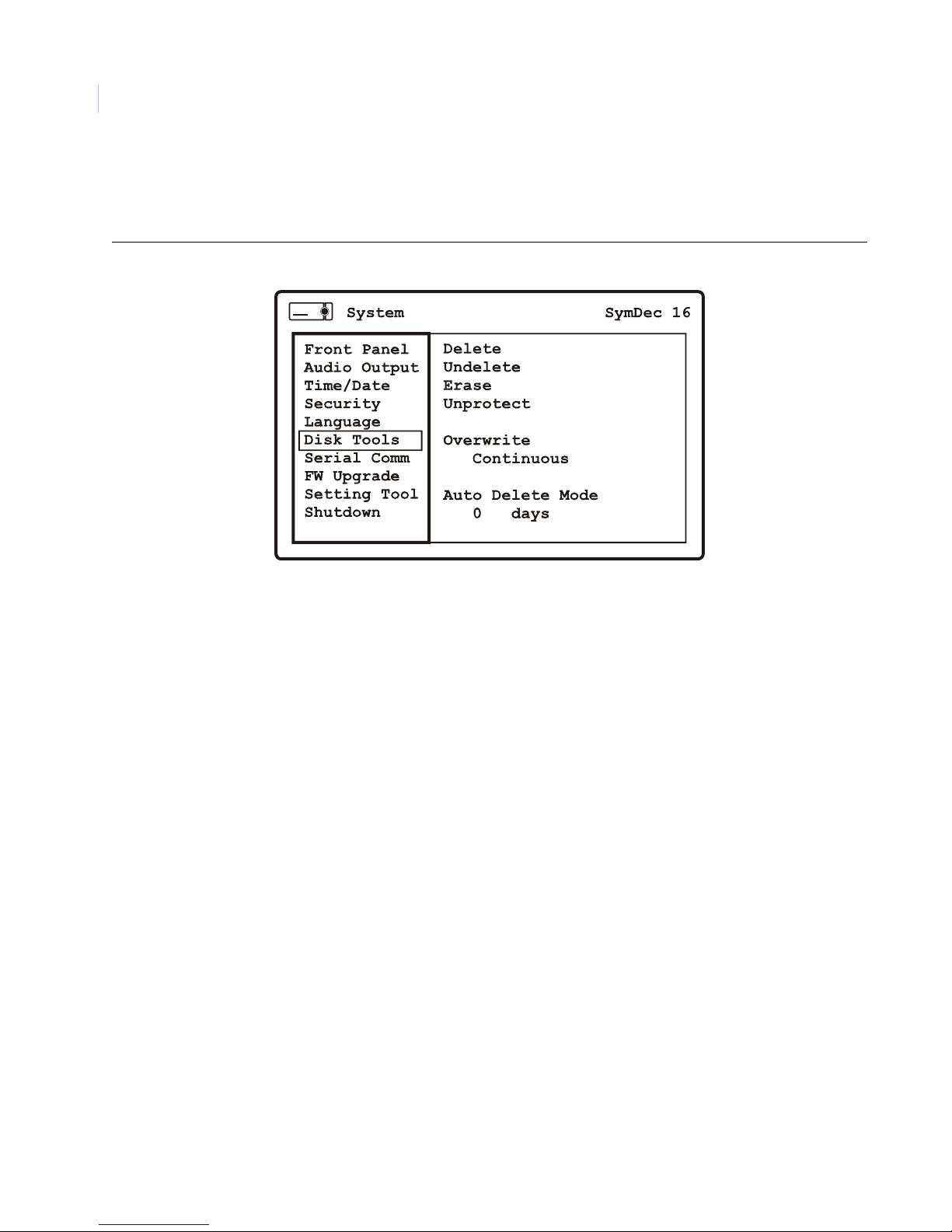
SymDec 16 plus 4
76
User Manual
Disk Tools
Use this menu to access the SymDec 16 plus 4’s hard disk maintenance features.
Figure 53. The System/Disk Tools menu
Page 87
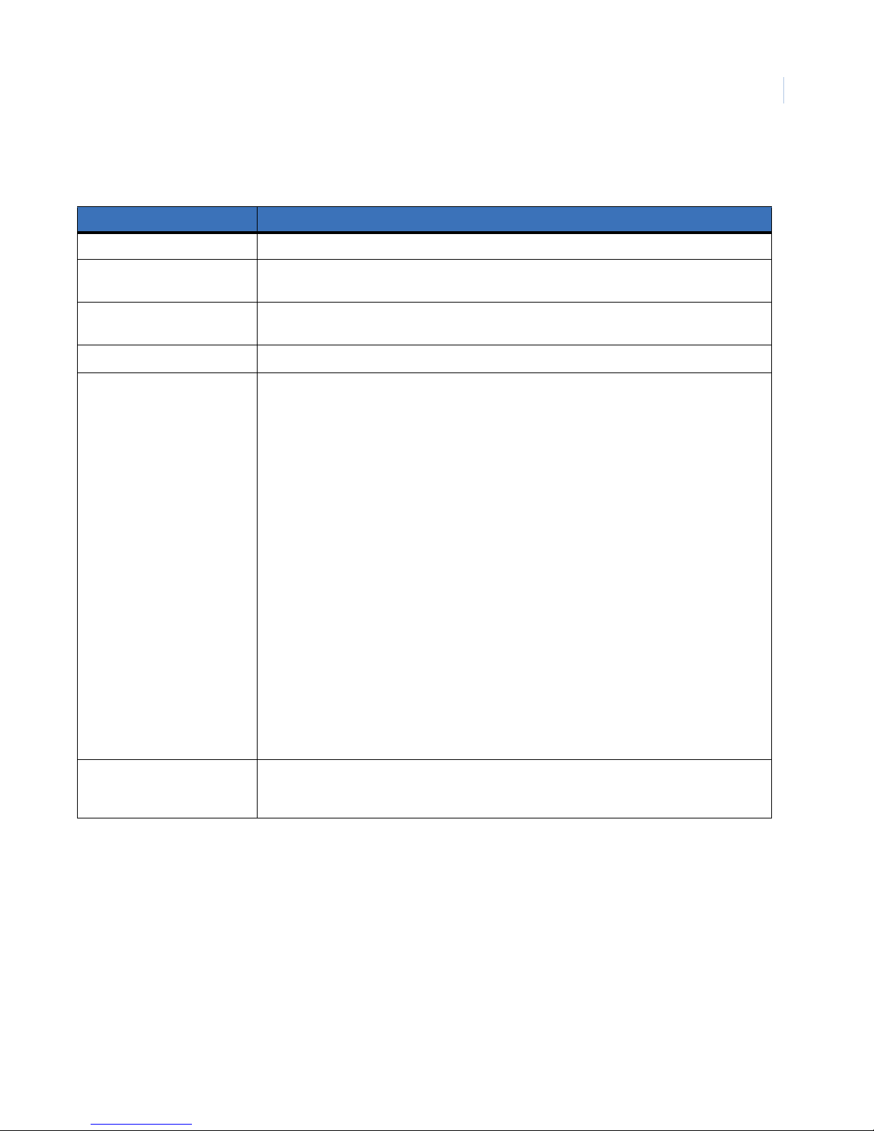
Programming the SymDec 16 plus 4
Chapter 4
Table 37. The System/Disk Tools men options
Menu Options Settings
Delete Select and press the enter button to delete all data on the hard drives. Requires PIN number.
Undelete Select and press the enter button to undelete all data on the hard drives. Only works after a
delete command. Requires PIN number.
Erase Select and press the enter button to erase all data on the hard drives. Requires PIN number.
Data is not recoverable with the Undelete command.
Unprotect/Protect All, By Clip, By Range (Protects/unprotects selections from deletion on hard disk)
Overwrite Continuous:
• Recording always starts at end of last recording.
• The unit overwrites all previously recorded data.
• The unit overwrites newly recorded data (data from the current record session).
• Unit never stops recording.
Write Once:
• Recording always starts at end of last recording.
• The unit overwrites all previously recorded data.
• Recording stops before the unit overwrites any of the newly recorded data (data from the
current record session).
• When the end of the disk is reached, the unit displays an on-screen message indicating
that the disk is full, and the unit has stopped recording. User must acknowledge the onscreen message by clicking the Enter button.
• The unit will continue recording again when the user clicks the Record button.
No Overwrite:
• Recording always starts at end of last recording.
• Recording stops when end of disk is reached (when disk is full).
• When the end of the disk is reached, the unit displays an on-screen message indicating
that the disk is full, and the unit has stopped recording. User must acknowledge the onscreen message by pressing the Enter button.
• Unit will not record over previously recorded data.
77
Auto Delete Mode (ADM) 0-999 days (prevents the unit from displaying or archiving any data that is more than the
selected number of days old. This feature may be required by law in some jurisdictions, please
consult with the local authorities).
Page 88
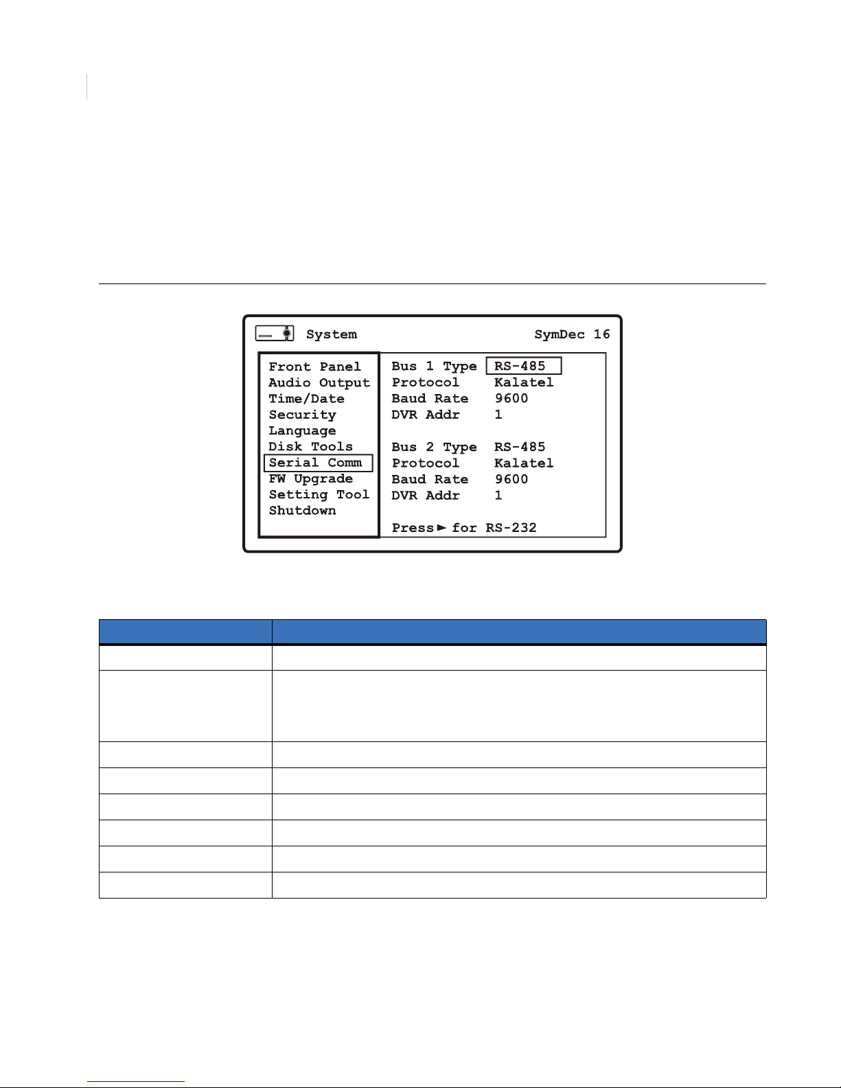
SymDec 16 plus 4
78
User Manual
Serial Communications
Use these menus to setup the serial communication properties of the SymDec 16 plus 4.
RS-485/RS-422
This menu sets the I/O connector on the rear panel to RS-485 or RS-422.
Figure 54. The System/RS-485 and RS-422 menu
Table 38. The System/RS-485 and RS-422 menu options
Menu Options Settings
Bus 1 Type RS-485 or RS-422
Protocol Kalatel, Passthrough, Power Dome, BaxNet, Digiplex, Pelco P, Pelco D (Kalatel is used for
controlling PTZ cameras using SymNav. Passthrough is referring to serial passthrough which
is setup in the Network/Passthrough dialog. If you set Bus 1 to serial passthrough then the
Protocol options must be set to Passthrough.
Baud Rate 300, 1200, 2400, 4800, 9600, 19200
DVR Address 0-199
Bus 2 Type RS-485 or RS-422
Protocol Kalatel, Passthrough, Power Dome, BaxNet, Digiplex, Pelco P, Pelco D
Baud Rate 300, 1200, 2400, 4800, 9600, 19200
DVR Address 0-199 (Dome addressing)
Page 89
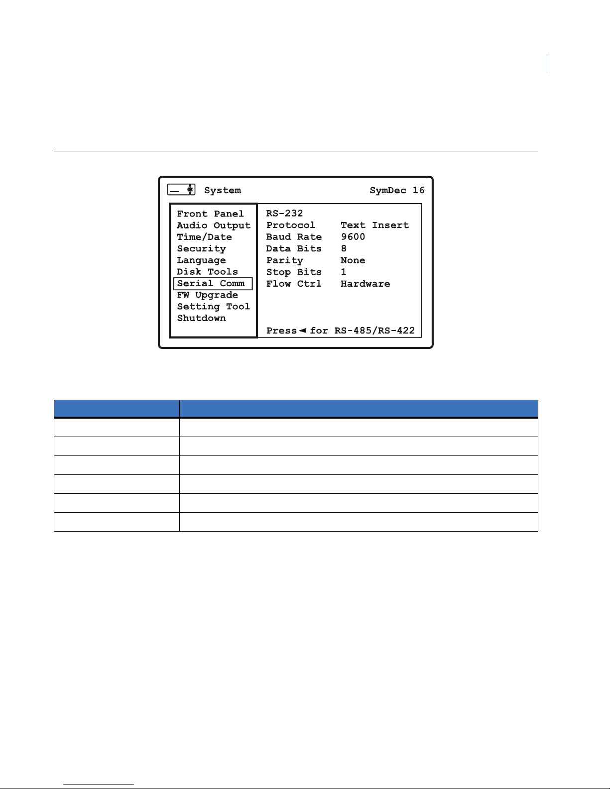
Programming the SymDec 16 plus 4
RS-232
USe this menu to setup the RS-232 parameters of the RS-232 connector on the rear panel.
Figure 55. The System/Serial Communication/RS-232
Chapter 4
79
Table 39. The System/Serial Communication/RS-232 options
Menu Options Settings
Protocol Text Insertion
Baud Rate 300, 1200, 2400, 4800, 9600, 19200, 38400, 57600, 115200
Data Bits 5, 6, 7, 8
Parity None, Even, Odd
Stop Bits 1 or 2
Flow Control None, Xon, Xoff
Page 90
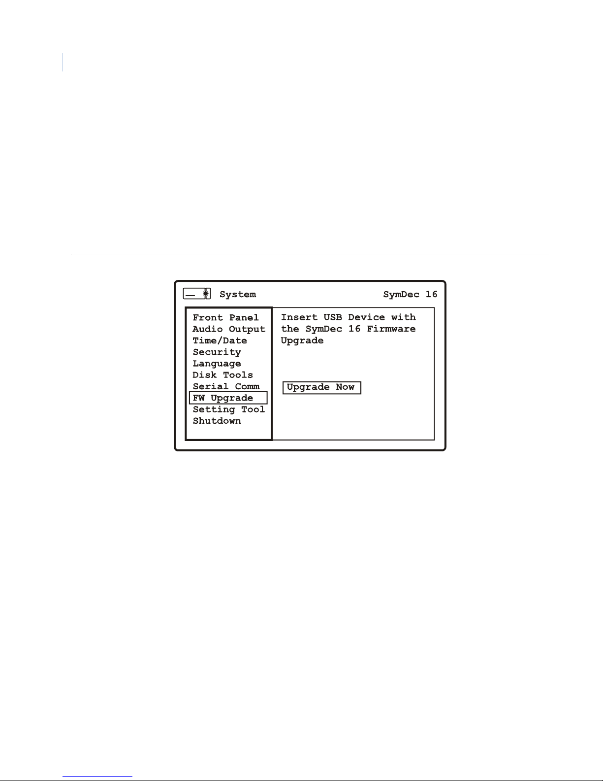
SymDec 16 plus 4
80
User Manual
Firmware Upgrade
Use this menu to upgrade the firmware (from a USB flashdrive) of the SymDec 16 plus 4. To upgrade do the
following:
1. Insert a USB flashdrive, with the flash upgrade file, into one of the USB ports.
2. Navigate to the Upgrade Now command and press the enter button.
3. The SymDec will reboot when completed.
Note: The flash upgrade file must be in the root directory of the flashdrive. Do not remove power while an upgrade is in-
process.
Figure 56. The System/Firmware Upgrade menu
Page 91
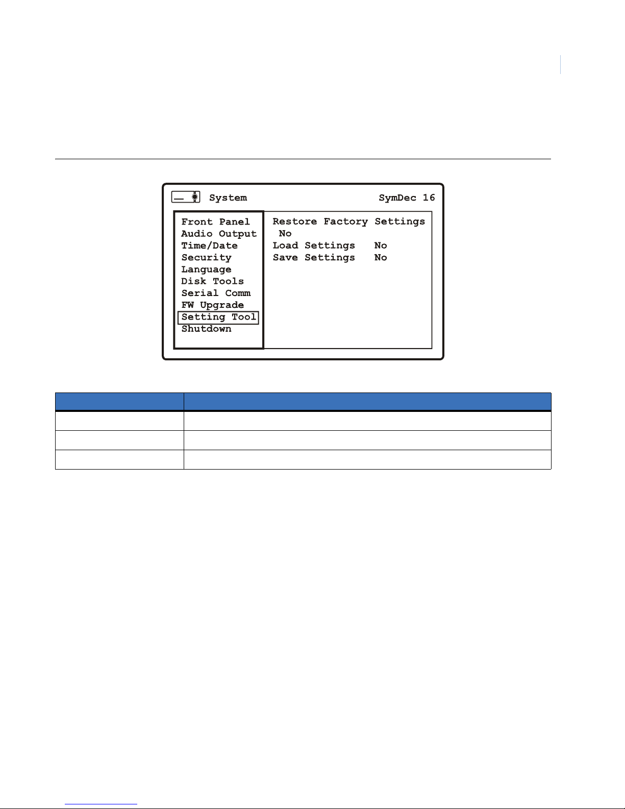
Programming the SymDec 16 plus 4
Setting Tool
Use this menu to restore factory setting, load and save settings to a USB flashdrive.
Figure 57. The System/Setting Tool
Chapter 4
81
Table 40. The System/Setting Tool option
Menu Options Settings
Restore Factory Settings Select Yes to restore
Load Settings Select Yes to load settings from a USB Flashdrive
Save Settings Select Yes to save settings to a USB Flashdrive
Page 92
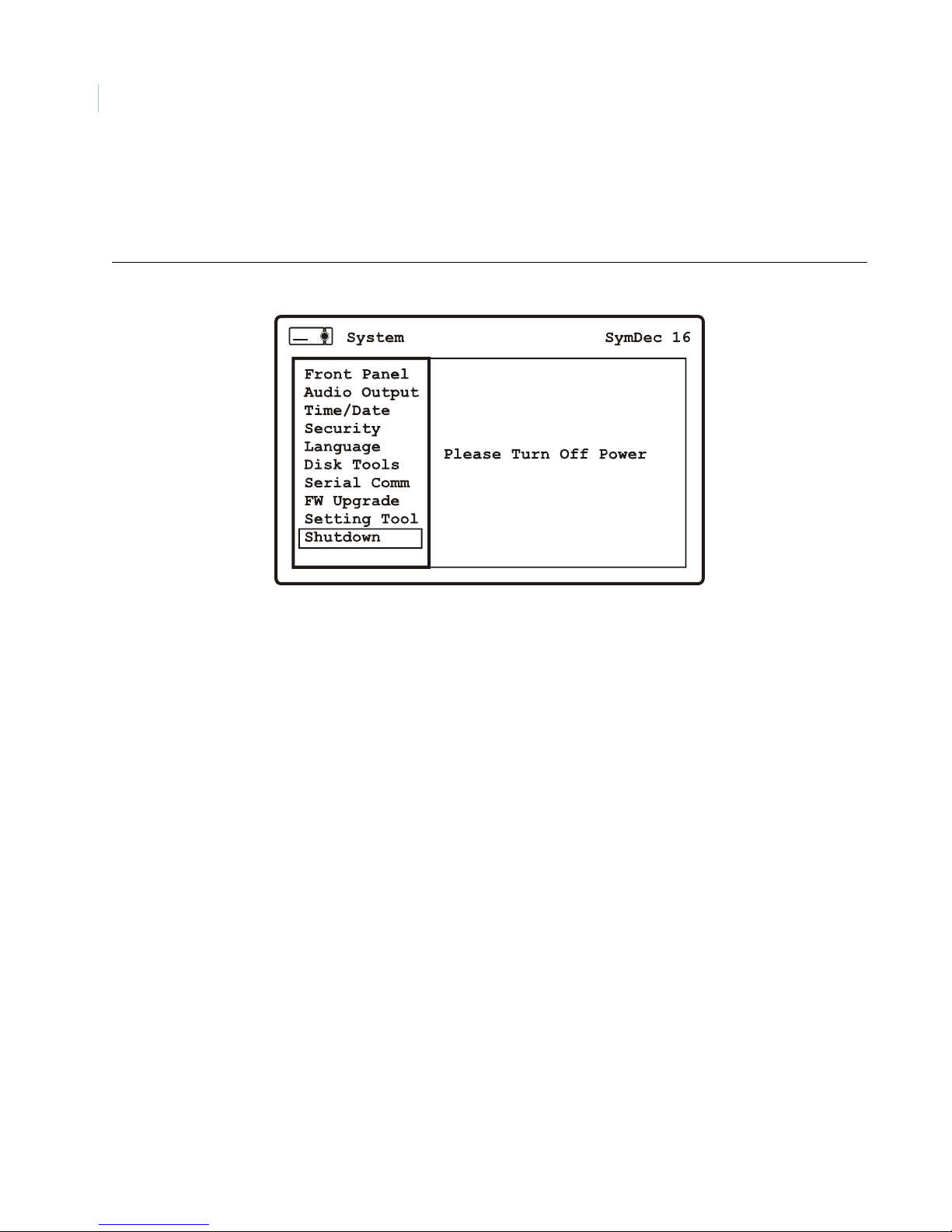
SymDec 16 plus 4
82
User Manual
Shutdown
Use this menu to shutdown the SymDec 16 plus 4 safely. Navigate to the Shutdown Now command and press
the enter button. Enter the password and press the enter button.
Figure 58. The System/Shutdown menu
Page 93
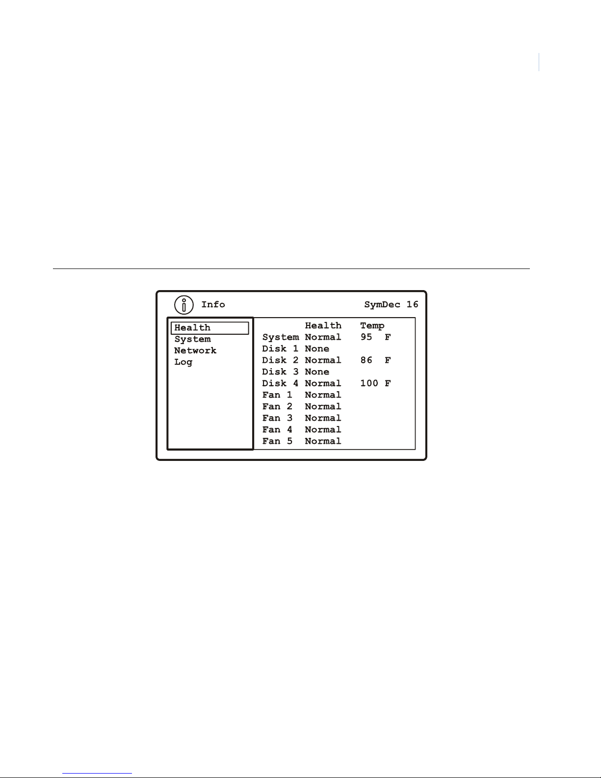
Programming the SymDec 16 plus 4
Chapter 4
The Info menu
Highlight the Info icon and press the enter button. The Info menu will appear.The Info menu contains the
following options and their settings:
Health
The Health menu display information on the following:
•System
•Disk 1 -4
•Fans 1-5
Figure 59. The Info/Health menu
83
Page 94
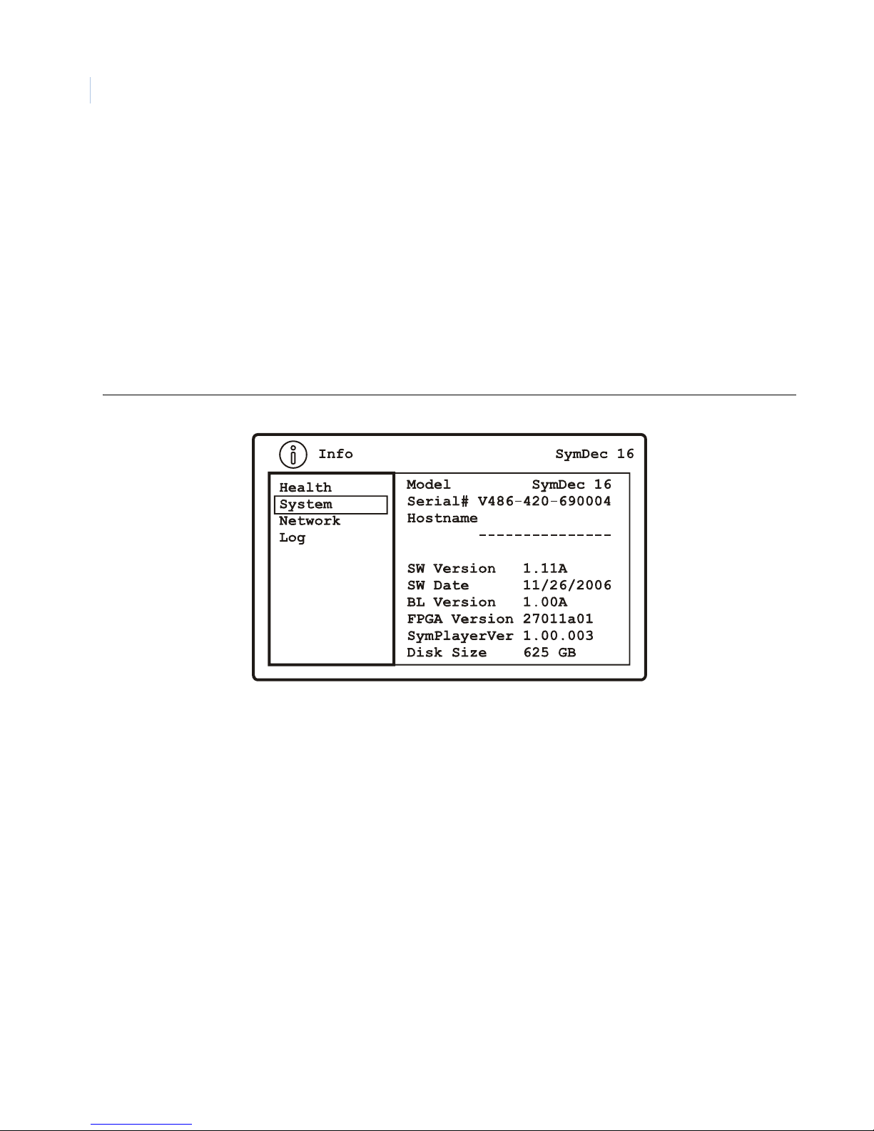
SymDec 16 plus 4
84
User Manual
System
The System menu display information on the following:
•Model
• Serial Number
•Hostname
• Software Version
• Software Date
•BL Version
•FPGA Version
•Disk Size
Figure 60. The Info/System menu
Page 95
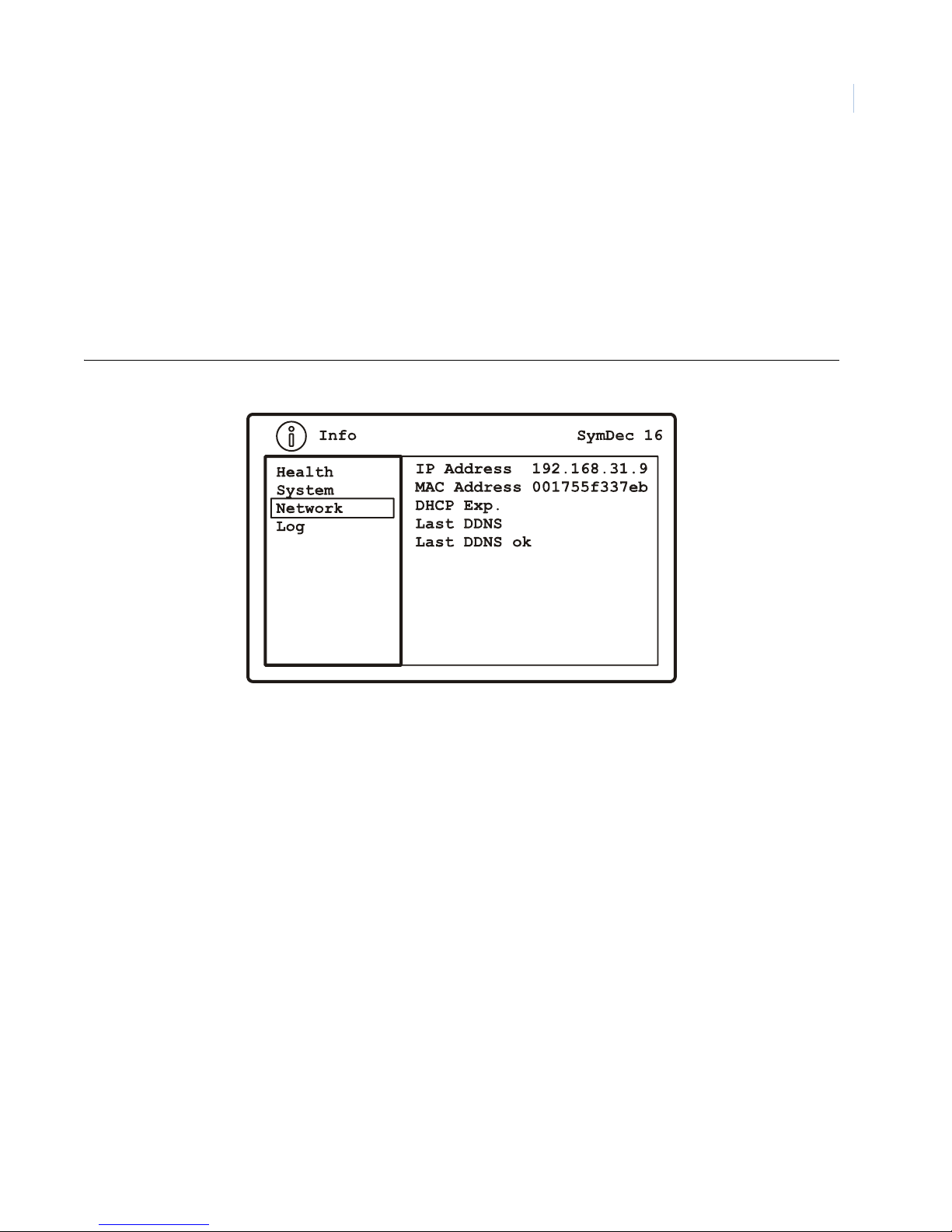
Network
The Network menu display information on the following:
• IP Address
• MAC Address
• DHCP Lease Expires
• Last DDNS Update Status
• Last DNS Update Success
Figure 61. The Info/Network menu
Programming the SymDec 16 plus 4
Chapter 4
85
Page 96
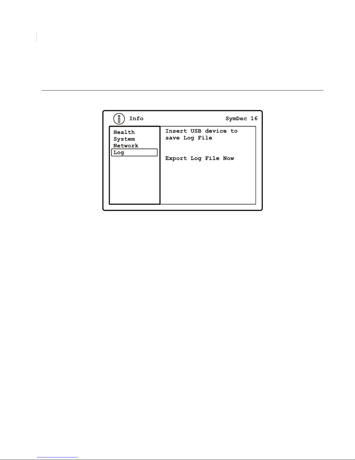
SymDec 16 plus 4
86
User Manual
Log
The log menu allows you to save the Log file to a USB device.
Figure 62. The Info/Network menu
The log file provides information on unit status, unit information, and hard drive temperatures. An example log
file is shown below.
SymDec16 Log
Serial Number: V406-206-6N0010
Mac Address: 001755f33906
12/21/2006 11:06:53 Network Link Down
12/21/2006 11:06:53 System Start
12/29/2006 04:43:59 Network Link Down
12/29/2006 04:43:59 System Start
01/05/2007 04:56:59 Network Link Down
01/05/2007 04:56:59 System Start
01/05/2007 05:05:08 Network Link Down
01/05/2007 05:05:08 System Start
01/10/2007 03:03:51 Network Link Down
01/10/2007 03:03:51 System Start
01/10/2007 03:45:06 Network Link Up
09/23/2006 00:01:31 Network Link Down
09/23/2006 00:01:31 System Start
09/23/2006 00:02:26 Network Link Up
09/23/2006 00:07:56 Network Link Down
09/23/2006 01:52:27 Network Link Up
Page 97

Chapter 5 SymNav and SymBrowser
This chapter provides detailed information on
• how to install the SymNav video software; and
• how to access and use the embedded SymBrowser.
In this chapter:
SymNav . . . . . . . . . . . . . . . . . . . . . . . . . . . . . . . . . . . . . . . . . . . . . . . . . . 88
Minimum System Requirements . . . . . . . . . . . . . . . . . . . . . . . . . . . . 88
Installing SymNav software from CD-ROM. . . . . . . . . . . . . . . . . . . 88
Starting SymNav software . . . . . . . . . . . . . . . . . . . . . . . . . . . . . . . . 88
The SymBrowser Webserver . . . . . . . . . . . . . . . . . . . . . . . . . . . . . . . . . . 90
Search. . . . . . . . . . . . . . . . . . . . . . . . . . . . . . . . . . . . . . . . . . . . . . . . 91
User . . . . . . . . . . . . . . . . . . . . . . . . . . . . . . . . . . . . . . . . . . . . . . . . . 92
Configure options. . . . . . . . . . . . . . . . . . . . . . . . . . . . . . . . . . . . . . . 93
Cameras . . . . . . . . . . . . . . . . . . . . . . . . . . . . . . . . . . . . . . . . . . . . . . 94
Schedule . . . . . . . . . . . . . . . . . . . . . . . . . . . . . . . . . . . . . . . . . . . . . 102
Alarms . . . . . . . . . . . . . . . . . . . . . . . . . . . . . . . . . . . . . . . . . . . . . . 104
Network . . . . . . . . . . . . . . . . . . . . . . . . . . . . . . . . . . . . . . . . . . . . . 106
System. . . . . . . . . . . . . . . . . . . . . . . . . . . . . . . . . . . . . . . . . . . . . . . 114
Info . . . . . . . . . . . . . . . . . . . . . . . . . . . . . . . . . . . . . . . . . . . . . . . . . 121
Symbrowser . . . . . . . . . . . . . . . . . . . . . . . . . . . . . . . . . . . . . . . . . . 123
Page 98
SymDec 16 plus 4
88
User Manual
SymNav
SymNav software provides remote video viewing and SymDec 16 menu setup with your PC. Make sure all
connections are completed, at a minimum the power cord, a viewing monitor, and an Ethernet cable must be
connected from the SYmDec 16 plus 4 and your PC.
Minimum System Requirements
The following minimum system requirements must be met before software installation.
Windows® 2000/XP and Direct X are registered trademarks of Microsoft Corporation.
Table 41. SymNav minimum system requirements
Hardware Specification
CPU Pentium 2.8 GHz or faster
RAM 512 MB
Hard disk drive 50 MB free hard drive space
Monitor SVGA, 1024 X 768, 24 bit color
Video AGP or PCI Express, 128 MB DDR Memory
Direct X Version 9 or higher
Operating system Windows® 2000 SP4, XP SP2
Installing SymNav software from CD-ROM
To install software on your hard disk from a CD:
1. Place the SymNav software CD in the CD-ROM drive of a PC that meets the minimum system
requirements.
2. Follow the instructions for installation as they appear.
3.
Note: If Autorun is not enabled on your PC, choose Run from the Start Menu, then type d:\setup.exe (where “d” is the drive
letter of your CD-ROM) and click OK. Follow the instructions as they appear on your screen.
Starting SymNav software
To start the SymNav software, double-click on the SymNav software desktop icon or choose Programs
from the Start menu and then select SymNav software. The Main window of the SymNav software program
will appear. For operating details, please see the SymNav software manual.
Note: The SymNav manual in pdf format is located on the SymNav software CD.
Page 99
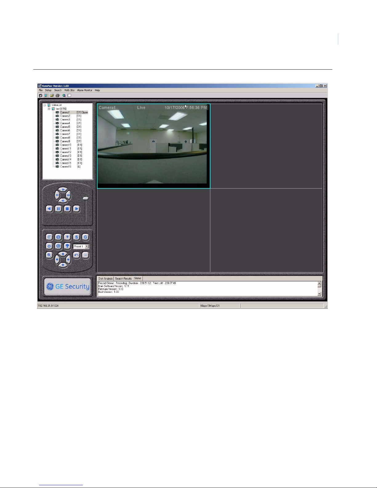
Figure 63. The SymNav main operation screen
SymNav and SymBrowser
Chapter 5
89
Page 100
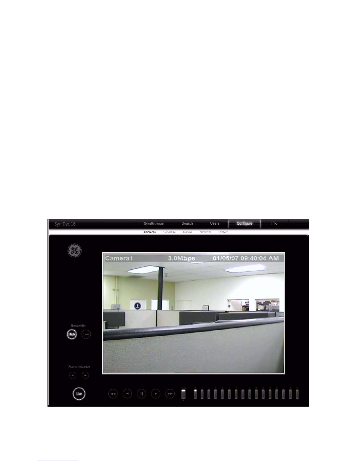
SymDec 16 plus 4
90
User Manual
The SymBrowser Webserver
The SymDec 16 plus 4 has an integrated WebServer interface. The WebServer provides you the means to
remotely configure, upgrade, and view information about the SymDec 16 plus 4. The default IP address from
the factory is 192.168.1.82. To disable the SymBrowser, go to Services on page 63 and change the HTTP port
number from the default 80 to 0.
To access the web interface:
1. Launch Internet Explorer (version 5.5 or later) on any local Internet connected PC or laptop.
2. Type in the unit’s IP address (192.168.1.82) or hostname (see network settings page) in the address
field and click enter.
Note: When launching, SymBrowser checks your system for the correct files. If they are not detected, SymBrowser
will attempt to load them. Accept all General Electric signed content to allow the files to be loaded.
3. The Enter Network Password screen will appear. Enter your user name and password (PIN). See
Passwords on page 7 for the default factory passwords.
4. The SymDec 16’s SymBrowser home page window should appear.
Figure 64. SymDec 16 plus 4 SymBrowser home page
On this page you will find links for SymBrowser, Search, User’s, Configure, and Info.
Note: The SymBrowser is discussed in detail at the end of this chapter.
 Loading...