

GE STS-400-25-4, STS-400-40-3, STS-400-25-3, STS-400-40-4, STS-400-63-4 Installation And Operating Manual
...Page 1

g
GE Consumer & Industrial
Digital Energy™
INSTALLATION and
OPERATING MANUAL
Digital Energy™ STS-400-25/40/63/100-3/4
Static Transfer Switch
400V-25/40/63/100A-3/4-pole
GE Digital Energy™
General Electric Company Telephone +41 (0)91 / 850 51 51
CH - 6595 Riazzino (Locarno) Fax +41 (0)91 / 850 51 44
Switzerland Website www.gedigitalenergy.com
STS
GE imagination at work
Ver 1.1 - GB
Page 2

Digital Energy™ Static Transfer Switch
g
INSTALLATION AND OPERATING MANUAL
Digital Energy STS-400-25/40/60/100 Static Transfer Switch
LX-DOC File: OPM_STS_400_25A_100_1GB_V011
Manual version 1.1 June 2004
INSTALLATION and
OPERATING MANUAL
Digital Energy™ STS-400-25/40/63/100-3/4
Static Transfer Switch
400V-25/40/63/100A-3/4-pole
Preface
We thank you for selecting a General Electric Digital Energy™ STS Series Static Transfer Switch and
recommend that you read these instructions carefully before installation and start-up of the device.
The instructions in this manual are for:
the 3-phase 3-pole models STS-400-25-3, STS-400-40-3, STS-400-63-3 and STS-400-100-3;
the 3-phase 4-pole models STS-400-25-4, STS-400-40-4 and STS-400-63-4.
Please keep this manual in a safe place for future reference and carefully read the important safety instructions
in chapter 1 before installation of this device.
© 2004 by GE Consumer & Industrial
All rights reserved.
The information contained in this publication is intended solely for the purposes indicated.
The present publication and any other documentation supplied with the Static Transfer Switch system is not to be reproduced, either in part
or in its entirety, without the prior written consent of GE.
The illustrations and plans describing the equipment are intended as general reference only and are not necessarily complete in every
detail.
The content of this publication may be subject to modification without prior notice.
OPM_STS_400_25A_100_1GB_V011
1
GE DE STS: installation and operating manual 1.1 (GB)
Page 3

Digital Energy™ Static Transfer Switch
g
CONTENTS
1 IMPORTANT SAFETY INSTRUCTIONS ..................................................................3
1.1 Save these instructions
1.2 Safety warnings and symbols
1.3 General
1.4 Intended use
1.5 Transport, storage, unpacking
1.6 Installation
1.7 Electrical connection
1.8 Operation
1.9 Fire regulations
1.10 Standards applied and conformity
2 INTRODUCTION .......................................................................................................8
2.1 Warranty
2.2 Description
2.3 Application
2.4 Fuses and TVSS circuits
3 INSTALLATION ........................................................................................................16
3.1 Transport
3.2 Unpacking
3.3 Location
3.4 Installation
3.5 Connection
3.6 Starting up
4 OPERATION ............................................................................................................21
4.1 Operation mode settings
4.1.1 Preferred source selection
4.1.2 Automatic retransferring
4.1.3 Manual operation
4.1.4 Reset button
4.2 Manual bypass operation
4.2.1 Bypassing load to primary source
4.2.2 Return from primary bypass mode to STS operation
4.2.3 Bypassing load to secondary source
4.2.4 Return from secondary bypass mode to STS operation
4.3 Service
4.3.1 STS operation test
4.3.2 Main fuse exchange procedure
4.3.3 TVSS fuse exchange procedure
4.3.4 Trouble shooting
4.4 Parameter settings (dip switches)
4.5 Default dip switch settings
4.6 Terminals
4.6.1 Relay communication terminal block
4.6.2 Communication Interface Module CI-M1
4.6.3 High current terminal
4.7 Fuse selection
5 SPECIFICATIONS ...................................................................................................43
5.1 Technical data
5.2 Dimensions
OPM_STS_400_25A_100_1GB_V011
2
GE DE STS: installation and operating manual 1.1 (GB)
Page 4
Digital Energy™ Static Transfer Switch
g
1 - Important Safety Instructions
1.1 Save these instructions
This manual contains important instructions that should be followed during erection, installation, use
and maintenance of the Static Transfer Switch. Before attempting to erect, install and use of the
device, carefully read this manual. Keep this manual next to the device for future references
Full understanding of and compliance with the safety instructions and warnings
contained in this manual are
THE ONLY CONDITION
to avoid any dangerous situation during erection, installation, operation and
maintenance work, and to preserve the maximum reliability of the system.
In the event of equipment failures or special problems it is not permitted to take unauthorised remedial
action. In such cases the responsible GE technical service department must be contacted and the
GE refuses any responsibility in case of non-observance, unauthorized alterations or improper use of
While every care has been taken to ensure the completeness and accuracy of this manual, GE accepts
This document shall not be copied nor reproduced without the permission of GE.
Due to technical improvements, some of the information contained in this manual may be changed
1.2 Safety warnings and symbols
Safety warnings
The text of this manual contains warnings to avoid risk to persons and to avoid damages to the UPS
The non-observance of the warnings reminding hazardous situations could result in human injury and
required information obtained.
the delivered device.
no responsibility or liability for any loss or damage resulting from the use of the information contained in
this document
without notice
system and the supplied critical loads. Do not proceed beyond these warnings if you do not fully
understand and/or are not able to meet the mentioned conditions.
equipment damage. Please pay attention to the meaning of the following warnings and symbols.
WARNING !
Refers to procedures or operations which, when not correctly performed,
could cause personal injury or serious damage to the system
NOTE
Warns the user about important operations or procedures described in this
manual
Safety Symbols
CAUTION
The product may be in danger: when procedures or operations are not
correctly performed, damage to the product may be the result.
DANGER OF PARTS ELECTRICALLY LIVE
Related to all situations with potentially hazardous voltage
OPM_STS_400_25A_100_1GB_V011
3
GE DE STS: installation and operating manual 1.1 (GB)
Page 5
Digital Energy™ Static Transfer Switch
g
1.3 General
DANGER!
RISK OF ELECTRIC SHOCK.
When the STS operates, some of its parts are necessarily under a hazardous
voltage.
Do not remove the cover; there are no user serviceable parts inside.
There may be danger, loss of life or personal injury if warnings are not strictly
observed.
CAUTION
There may be damage to the equipment if procedures and practices are not
strictly observed and followed.
NOTE
Do not attempt to service the STS unless you have had proper training. Refer
all maintenance and servicing to properly qualified, skilled and competent
service personnel.
Properly qualified, skilled and competent service personnel are persons who:
• Are familiar with the erection, installation and operation of the equipment and the system that is
being installed.
• Are capable of performing switching operations according to safety technology standards and
entitled and authorized to switch the equipment on and off and to isolate from the voltage.
• Are instructed according to the standards of safety technology in the care and use of safety
equipment.
• Are trained to immediate rescue measures (first aid).
• Have completed instructions with appropriate confirmation of GE.
1.4 Intended use
• A Static Transfer Switch (STS) is designed to transfer power supply between independent AC power
sources, thus protecting the connected load from power supply interruptions. It protects automatic
systems for power industry, power supply systems for petrochemical industry, computer and
telecommunication centers, automatic and security systems of ‘intelligent’ buildings as well as other
equipment that is highly sensitive for power supply interruptions.
• The STS is intended to be operated by technically qualified personnel.
Technically qualified personnel are persons who (because of their training, experience, and position
as well as their knowledge of appropriate standards, regulations, health and safety requirements and
working conditions) are authorised to be responsible for the safety of the equipment, at all times whilst
carrying out their normal duties and are therefore aware of, and can report, possible hazards (observe
IEC 364, DIN VDE 0105 and national wiring regulations and accident prevention rules).
• The technical data as well as information concerning connecting requirements can be found on the
rating label and in this document and shall be strictly observed.
OPM_STS_400_25A_100_1GB_V011
4
GE DE STS: installation and operating manual 1.1 (GB)
Page 6

Digital Energy™ Static Transfer Switch
g
1.5 Transport, storage, unpacking
• The STS should be transported in a container truck with shock protection against moves during
transport. The STS should be belted to the wall of the container.
• Any special treatment during storage of the STS is not needed.
• Move the STS in its original package to the final destination room.
• Check for sufficient floor and elevator loading capacity.
• Immediately after unpacking carefully check the integrity of the equipment. In case you note
recognizable damage, do not connect any voltage to the STS, do not put the STS into operation, but
contact the nearest Service Centre.
1.6 Installation
The following instructions are provided for the personal safety of operators and also for the protection
of the described product and connected equipment.
• Observe the prescribed accident prevention and safety rules for the specific application.
• When installing the STS strictly observe all information on technical data and operating conditions.
Comply with all warnings, and strictly follow the procedures and practices as described in this manual.
• This STS is intended to be used in a controlled indoor environment and free of conductive
contaminants and protected against animal intrusion.
• Check for sufficient floor loading capacity.
• Avoid placing the unit in direct sunlight or near heat sources.
• It is important that the unit has adequate ventilation. Maintain air movement around and through the
unit. Do not block the air vents.
• The unit must be placed in a sufficiently ventilated area; the ambient temperature should not exceed
40°C (104°F).
• Do not install the STS in an excessively humid environment or near water, relative humidity should not
exceed 90% at 20°C (68°F).
• Avoid spilling liquids or dropping any foreign object into the STS.
• Emergency stop devices must be provided for all applications. An emergency stop must inhibit any
further uncontrolled operation.
• The electric connections must be covered.
• Earth connection must be checked for safe function after assembly.
• Countermeasures should be taken to avoid accidental turning on of previously switched off systems
through either a control vault or a third party (e.g. key switches).
• Do not touch electronic components. They may be electrostatic sensitive and are for that reason easily
damaged due to improper handling.
• To avoid potential health risks, electrical components should not be mechanically damaged or
destroyed.
• Isolate from mains and battery before installation or dismantling work, as well as for fuse changes or
post installation modifications.
OPM_STS_400_25A_100_1GB_V011
5
GE DE STS: installation and operating manual 1.1 (GB)
Page 7
Digital Energy™ Static Transfer Switch
g
1.7 Electrical connection
• All electrical connections are to be realized by properly qualified, skilled and competent service
personnel only.
• When working on live STS, be sure to comply with the applicable national accident prevention rules.
• Before putting into operation make sure that the rated voltage for the unit corresponds to the local
supply voltage.
1.8 Operation
• These instructions cover normal operation in the automatic as well as in manual modes. Special
operating conditions, such as short circuit tests, input supplies, etc., are not covered in this document.
These operating modes require comprehensive knowledge of the overall system and should be carried
out by properly qualified, skilled and competent service personnel only. Refer to section 1.3 for further
details.
• Operators shall make sure that the system is ready for operation and that all cabinet doors are properly
closed before switching it on.
• Warning signs are placed on all cabinet doors to warn of excessive voltage (over 50 V) in the control
cabinets, but also of voltages in the power section and enormous short circuit currents. These signs
supply a warning not to open the doors during operation.
DANGER ! High Voltage!
Only qualified personnel may carry out work or manipulation of the device.
• Operators are prohibited from performing any work inside the control cabinets.
• Service and maintenance will not be covered in this document.
1.9 Fire regulations
WARNING
Should a fire break out inside the system, a fire extinguisher with CO2 or
halogen must be used. Do not inhale vapors.
OPM_STS_400_25A_100_1GB_V011
6
GE DE STS: installation and operating manual 1.1 (GB)
Page 8
Digital Energy™ Static Transfer Switch
g
1.10 Standards applied and conformity
European Standards
Standard
EN 60950
EN 50178 (project)
IEC 600076
IEC 60146-1-2
IEC 60529
IEC 60617
EN 50082-2
DIN 41773 Part 1
Safety of information technology equipment, including electrical
business equipment
Equipment of Power Plants with electronic resources
Power transformers
General requirements and line commutated converters
Degrees of protection provided by enclosures (IP codes)
Graphical symbols and diagrams
EMC Requirements
Static power converters, semiconductor rectifiers equipment with IU
characteristics for charging of Lead Acid batteries - guideline
The standards mentioned above fulfil the
Description
requirements for CE marking.
The product mentioned in this manual conforms to the relevant requirements to the appropriate EU
Directive, i.e. that this product meets all relevant EU Directives and that it can be sold inside the
European Union without national commercial hindrances.
Relevant EU Directives for GE are called EMC- and Low Voltage Directives:
• EU Directive on Electromagnetic Compatibility 89/336/EU, in version 92/31/EU, 93/68/EU
• EU Directive on Electrical Equipment designed for use within certain Voltage Limits (Low
Voltage Directive) 73/23/EU, in version 93/68/EU
The directives themselves define only on a modest scale what's to do and refer to the harmonised
Standards. One of the EU harmonised product standards is applicable for rectifier systems. According
to this standard GE fulfils the basic requirements.
OPM_STS_400_25A_100_1GB_V011
7
GE DE STS: installation and operating manual 1.1 (GB)
Page 9
Digital Energy™ Static Transfer Switch
g
2 - Introduction
2.1 Warranty
GE Digital Energy, operating through its authorized agents, warrants that the standard products will be free of
defects in materials and workmanship for a period of 24 months after the date of invoice, or such other period
as may be specified.
NOTE
This warranty does not cover failures of the product which result from incorrect
installation, misuse, alterations by persons other than authorized agents, or abnormal
operating conditions
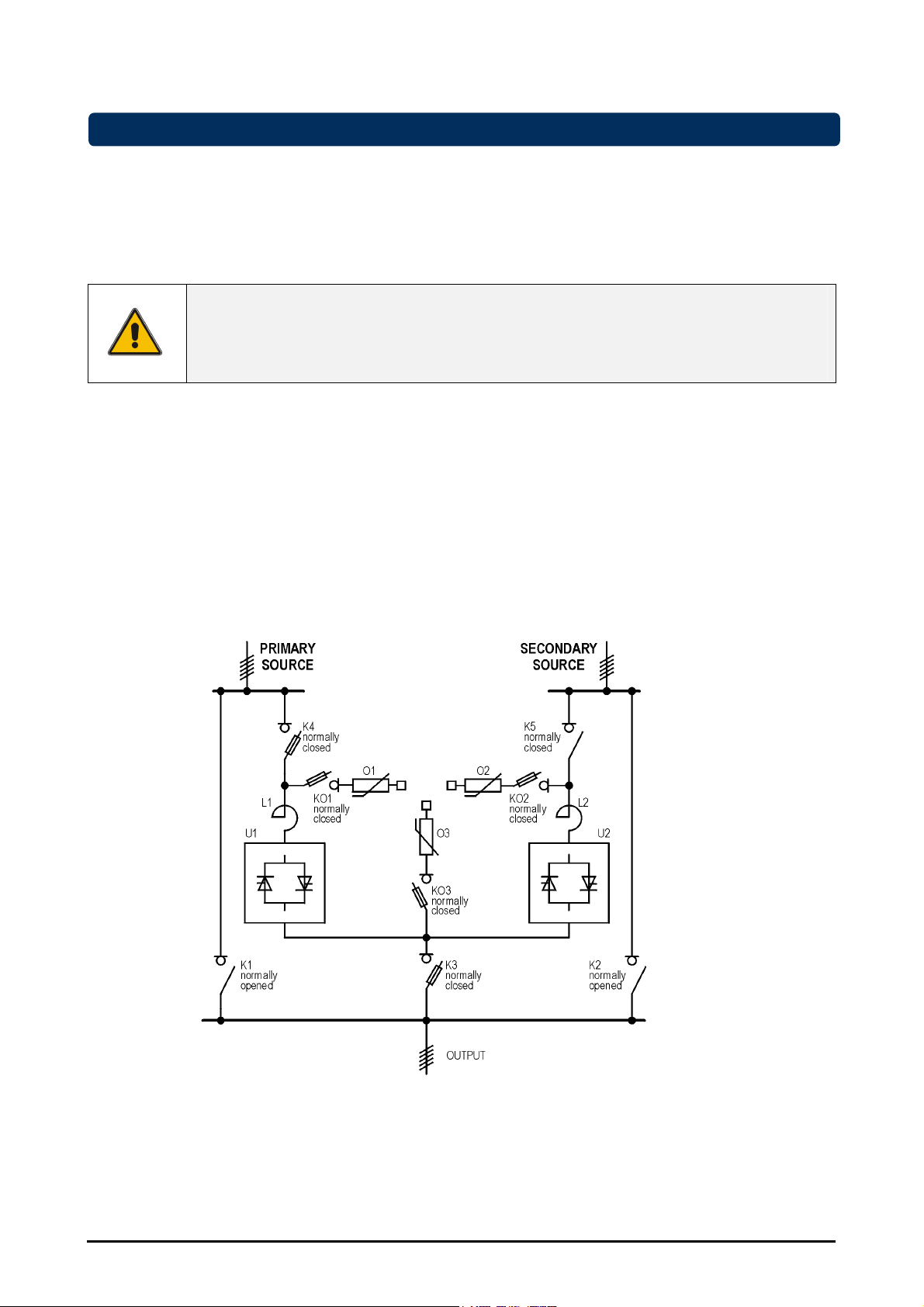
2.2 Description
Static Transfer Switches type STS-400-XX-3/4 (four 3-pole models STS-400-25/40/63/100-3 and three 4-pole
models STS-400-25/40/63-4) are designed for switching between two alternative electrical power sources
without interruption of the power supplied to the load. The neutral wires in the 3-pole STS type are connected
together, whereas the neutral wires in the 4-pole type are being switched the same way as the phase wires.
The static transfer switch (STS) is connected to two sources of electrical power with terminals called X01
PRIMARY SOURCE and X02 SECONDARY SOURCE. The rated voltage of both sources is 400V AC phaseto-phase and the frequency is 50Hz. Depending on the current settings and the state of the system, one of the
two sources (either the PRIMARY SOURCE or the SECONDARY SOURCE) is “connected” to the output
terminal called X03 STS OUTPUT. Possible methods for transferring the load from one source to other are
explained in chapter 4.
Figure 1. Electrical diagram of Static Transfer Switch (STS) with manual bypasses
Each single line on the diagram represents three wires inside the 3-pole STS and four wires inside the 4-pole
STS.
PRIMARY SOURCE, SECONDARY SOURCE and STS OUTPUT connections consist of five wires each
including Protective Earth (PE).
OPM_STS_400_25A_100_1GB_V011
8
GE DE STS: installation and operating manual 1.1 (GB)
Page 10
Digital Energy™ Static Transfer Switch
g
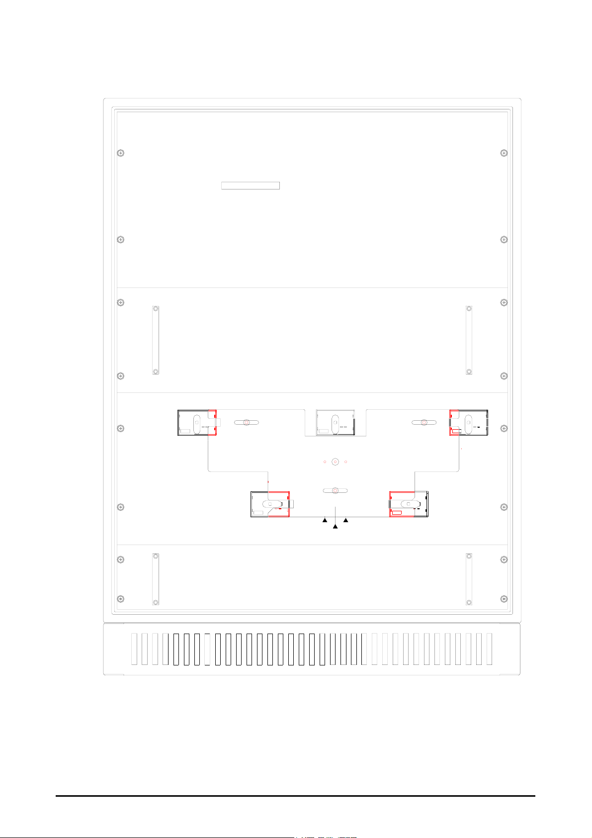
Five switches (figure 3) are set from the front panel without need for taking out the panel. These switches are
equipped with a mechanical interlock that prevents against short circuit between both supplying sources. Each
of them may be set manually into one of two positions: either “ON” or “OFF”. The device operates in STS mode
if the switches are set as in table 1.
Table 1
K1 STS
PRIMARY BYPASS
OFF
K2 STS
SECONDARY BYPASS
K3 STS
OUTPUT
K4 STS
PRIMARY SOURCE
K5 STS
SECONDARY SOURCE
OFF
ON
ON
ON
In normal mode of operation, the process of transferring the supply from one input to the other one is performed
automatically. The start up procedure is described in chapter 3, operation is explained in chapter 4.
The device is equipped with a mechanical interlock plate that prevents against unintentional short circuit during
manipulation with high current switches. The interlock plate is being moved aside during manipulation and may
be set in three positions: SECONDARY BYPASS, NORMAL MODE and PRIMARY BYPASS. The interlock
plate is equipped with a knurled nut that is screwed after a change of plate position. In that way the interlock
plate positions are locked with the knurled nut to prevent unintentional move of the plate.
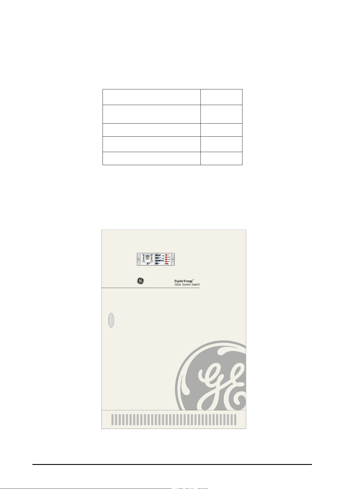
Figure 2. STS front
OPM_STS_400_25A_100_1GB_V011
9
GE DE STS: installation and operating manual 1.1 (GB)
Page 11
Digital Energy™ Static Transfer Switch
g
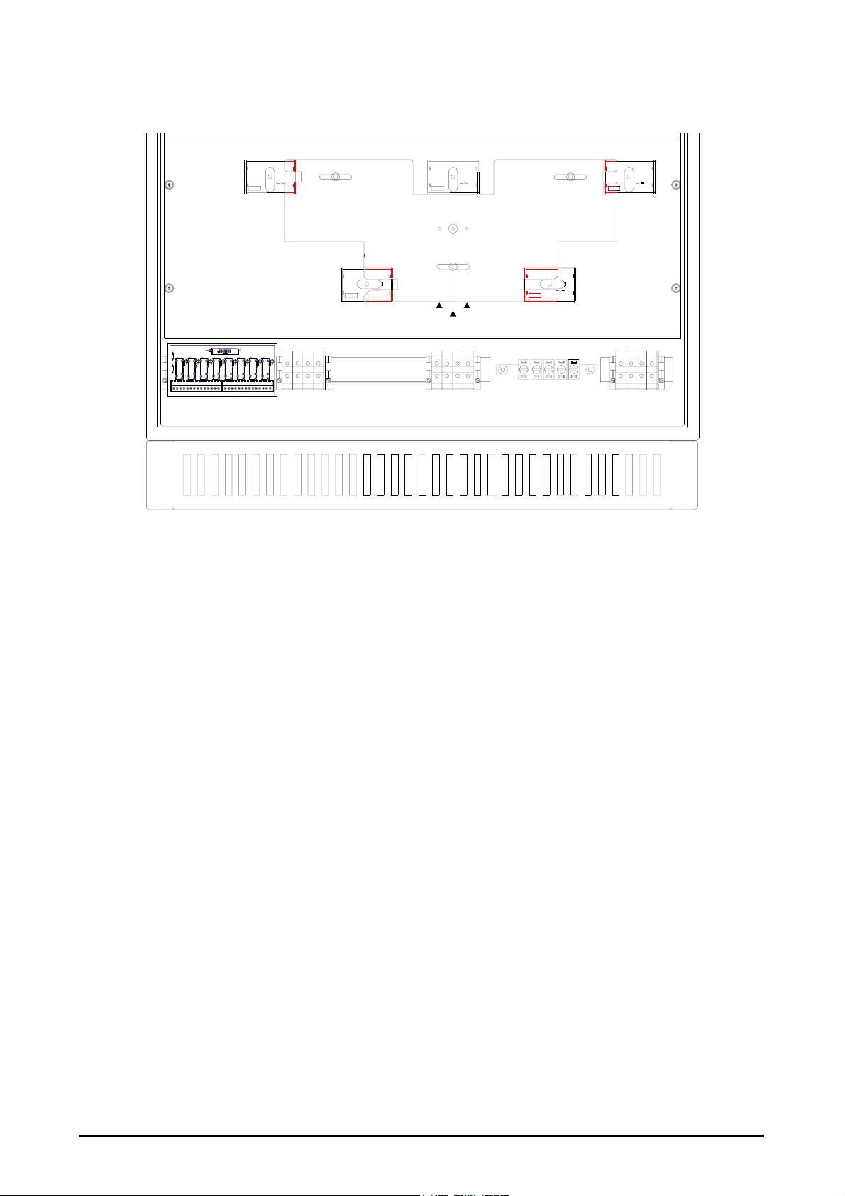
OFF
ON
MAIN AND AUXILARY FUSES
K4 STS
PRIMARY SOURCE
RELAY COMMUNICA TION
TERMINAL BLOCK
Figure 3. STS with opened door
SW1SW2SW3SW4SW5SW6SW8SW7
K1 STS
PRIMARY
BYPASS
XO1
PRIMARY SOURCE
K3 STS
OUTPUT
NORMAL
MODE
XO3
OUTPUT
K5 STS
SECONDARY SOURCE
PRIMARYSECONDARY
BYPASSBYPASS
K2 STS
SECONDARY
BYPASS
XO2
SECONDARY SOURCE
OPM_STS_400_25A_100_1GB_V011
10
GE DE STS: installation and operating manual 1.1 (GB)
Page 12
Digital Energy™ Static Transfer Switch
g
K4 STS
PRIMARY SOURCE
K1 STS
PRIMARY
BYPASS
N
1
X10 X11
1
14
14
L1 L2 L3
X01
Figure 4.a. High current terminals location for all types excluding STS-400-100-3
K3 STS
OUTPUT
PRIMARYSECONDARY
BYPASSBYPASS
NORMAL
MODE
L1 L2 L3
X03
(cover removed)
K5 STS
SECONDARY SOURCE
K2 STS
SECONDARY
BYPASS
PE PE PE
PE
N
PE
L1 L2 L3
X02
N
OPM_STS_400_25A_100_1GB_V011
11
GE DE STS: installation and operating manual 1.1 (GB)
Page 13
Digital Energy™ Static Transfer Switch
g
K4 STS
PRIMARY SOURCE
K1 STS
PRIMARY
BYPASS
1
1
14
X10 X11
14
L1 L2
X01
N
L3
Figure 4 b. High current terminals location for STS-400-100-3
K3 STS
OUTPUT
NORMAL
MODE
L1 L2
(cover removed)
X03
K5 STS
SECONDARY SOURCE
PRIMARYSECONDARY
BYPASSBYPASS
N
L3
K2 STS
SECONDARY
BYPASS
PE PE PE
PE
PE
L1 L2
X02
N
L3
OPM_STS_400_25A_100_1GB_V011
12
GE DE STS: installation and operating manual 1.1 (GB)
Page 14
Digital Energy™ Static Transfer Switch
g
O1
Primary Source
Fuses
KO1 KO2
K4 STS
PRIMARY SOURCE
Figure 5 a. Fuses and TVSS location (without STS-400-100-3)
Fuse burn
indication for
primary source
fuses
KO3
O3
K3 STS
OUTPUT
Output
Fuses
Fuse burn
indication for
output fuses
K5 STS
SECONDARY SOURCE
O2
OPM_STS_400_25A_100_1GB_V011
13
GE DE STS: installation and operating manual 1.1 (GB)
Page 15
Digital Energy™ Static Transfer Switch
g
O1
Primary Source Fuses
KO1
K4 STS
PRIMARY SOURCE
Figure 5b. Fuses and TVSS location for STS-400-100-3
Fuse burn
indication for
primary source
fuses
KO3
O3
K3 STS
OUTPUT
Output
Fuses
Fuse burn
indication for
output fuses
KO2
K5 STS
SECONDARY SOURCE
O2
OPM_STS_400_25A_100_1GB_V011
14
GE DE STS: installation and operating manual 1.1 (GB)
Page 16

Digital Energy™ Static Transfer Switch
g
2.3 Application
The STS-400-XX is designed to operate with two electrically separated electrical power sources connected to
terminals X01 PRIMARY SOURCE and X02 SECONDARY SOURCE. The sources are connected to the STS
with a five-wire cable each (three wires for the phases, one for neutral and one for PE). Electrical parameters of
the input sources (PRIMARY SOURCE and SECONDARY SOURCE) and output external circuit (STS
OUTPUT) should meet the specifications for the STS. Three cables coming into the STS, two from the sources
and one from the load, create three outgoing lines on the diagram showed in figure 1. Lines going from the
sources are called input lines and consequently the line going to the load is called output line. Input line voltage
and output line current values should not exceed acceptable ranges.
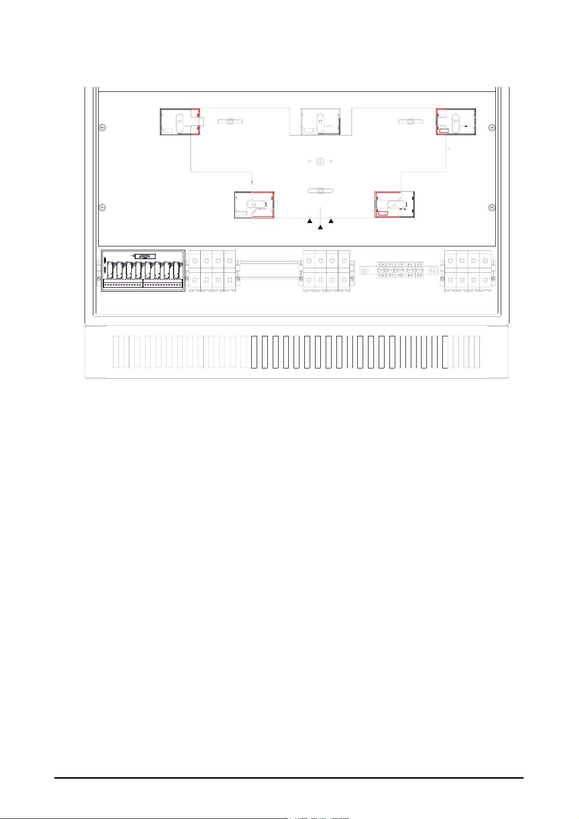
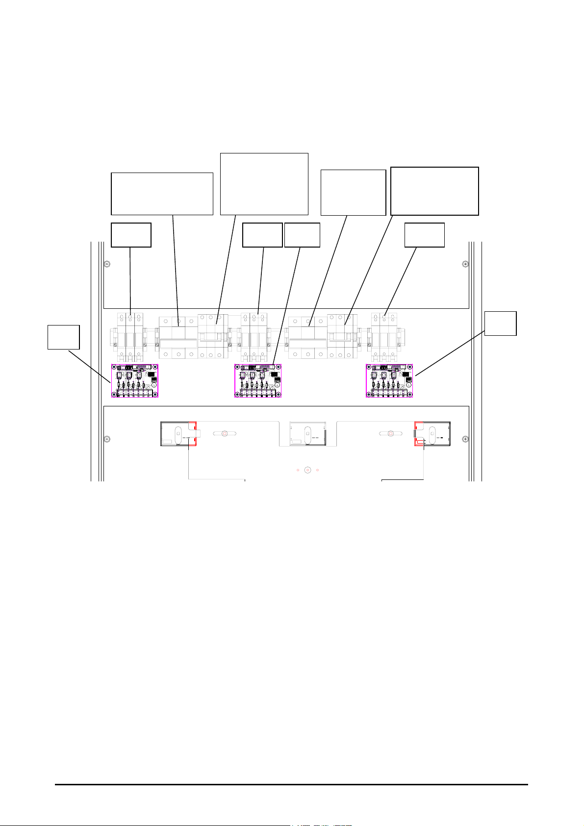
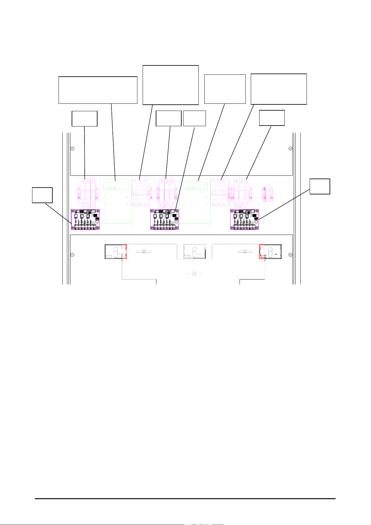
2.4 Fuses and TVSS circuits
Fuses and TVSS units (TVSS – Transient Voltage Surge Suppressor) are placed behind the plate with MAIN
AND AUXILARY FUSES label (figure 4). Exchange of fuses and TVSS units is possible after removing that
plate (figure 6).
Fuses are placed in the primary input line and in the output line (figure 1). Each fuse is equipped with a
signalling circuit which indicates a burnt fuse. The signalling circuit is based on an auxiliary overcurrent circuit
breaker which is connected in parallel to the main fuse. When the main fuse is burnt the auxiliary circuit breaker
is energized too. In this way the state of the auxiliary circuit breaker indicates which fuse was burnt. In case of
exchanging the burnt fuse, the auxiliary circuit breaker should be set into position “on”.
Each line (two input lines and output line) is protected by TVSS units against voltage transients. In case of short
circuit inside the TVSS unit caused by a voltage transient, each TVSS is equipped with an overcurrent circuit
breaker that cuts off the circuit with a burnt TVSS. TVSS burning is indicated by a LED diode placed on the
control panel (figure 7). In case of a TVSS alarm, each TVSS unit should be checked. Each burnt TVSS unit
should be replaced as well as its fuse.
OPM_STS_400_25A_100_1GB_V011
15
GE DE STS: installation and operating manual 1.1 (GB)
Page 17

Digital Energy™ Static Transfer Switch
g
3 - Installation
3.1 Transport
The STS should be transported in a container truck with shock protection against moves during transport. The
STS should be belted to the wall of the container. Because of limitation of height for air transport up to 1.6
meter, the STS is placed horizontally on a palette.
Move the STS in its original package to the final destination room using a pallet truck or forklift.
For storage and transport the cabinet of the Static Transfer Switch (STS) is covered with cardboard sheet
belted with steel wrapping bands to europalettes or other suitable for forklift transport.
The package box supplies the following information:
• Name or logo of manufacturer
• Quality control sign
CAUTION
During transport, pay attention to:
• Warnings according to PN-67/O-79252 Standard
Figure 6. View of crate package
In case of installing a STS on upper levels, four lifting eyes are available on top of the cabinet allowing transport
with a crane or others.
The STS should be stored in closed rooms free of chemically aggressive vapours, temperature 0°C to +40°C
(32°F to 104°F) and humidity lower than 90% at 20°C (68°F).
OPM_STS_400_25A_100_1GB_V011
16
GE DE STS: installation and operating manual 1.1 (GB)
Page 18

Digital Energy™ Static Transfer Switch
g
3.2 Unpacking
1. Cut the wrapping bands, and remove the shipping box.
2. Immediately after unpacking carefully check the integrity of the equipment. In case you note
recognizable damage,
• notify the carrier and place of purchase
• contact the nearest Service Center.
WARNING! In case of recognizable damage:
DO NOT connect any voltage to the unit
DO NOT put the unit into operation
3. Turn the unit into vertical position and place it on a frame. Screw the pedestal of the STS to the
frame.
4. Recycle the packing material in compliance with all applicable regulations.
3.3 Location
• This STS is intended to be used in a controlled indoor environment and free of conductive
contaminants and protected against animal intrusion.
• Check for sufficient floor loading capacity.
• Avoid placing the unit in direct sunlight or near heat sources.
• It is important that the unit has adequate ventilation. Maintain air movement around and through the
unit. Do not block the air vents.
• The unit must be placed in a sufficiently ventilated area; the ambient temperature should not exceed
40°C (104°F).
• Do not install the STS in an excessively humid environment or near water, relative humidity should not
exceed 90% at 20°C (68°F).
• Avoid spilling liquids or dropping any foreign object into the STS.
OPM_STS_400_25A_100_1GB_V011
17
GE DE STS: installation and operating manual 1.1 (GB)
Page 19

Digital Energy™ Static Transfer Switch
g
3.4 Installation
External cable connections are being made during the installation procedure.
• When installing the STS strictly observe all information on technical data and operating conditions.
Comply with all warnings, and strictly follow the procedures and practices as described in this manual.
• Do not touch electronic components. They may be electrostatic sensitive and are for that reason easily
damaged due to improper handling.
• To avoid potential health risks, electrical components should not be mechanically damaged or
destroyed.
NOTE
The STS may only be installed by properly qualified, skilled and competent
service personnel.
Refer to section 1.3 for further details.
CAUTION
Make sure that condensation does not occur as a result of a relatively low
temperature of the unit. Especially if transport took place at sub-zero
temperatures, allow the unit to warm up before installation and starting up.
NOTE
Before making any connection and switching on the STS, check the following
conditions.
• Make sure that the rated voltage and frequency for the unit corresponds with the local supply voltage
and frequency.
NOTE
Rated voltage of both sources is 400V AC phase to phase and the frequency
is 50Hz.
• Make sure that the total power requirement of the equipment connected to the STS does not exceed
the rated output power of the STS.
CAUTION
Wrong connection of the external sources to the STS may cause a fault inside
the STS and unpredicted operation of external devices connected to the STS.
OPM_STS_400_25A_100_1GB_V011
18
GE DE STS: installation and operating manual 1.1 (GB)
Page 20

Digital Energy™ Static Transfer Switch
g
3.5 Connection
1. Switch off the supply in both supplying lines outside the STS. Switches for both sources may be
placed in some distance to the STS depending on the topology of the rest of the power system.
2. Check the absence of the voltage in the two input lines with a proper voltmeter.
3. Open the door of the STS.
4. Set the switches into positions as in table 2.
5. Unscrew 4 screws (figure 3) from the lowest panel and take the panel out.
6. Firmly connect five wires coming from the first supplying device (PRIMARY SOURCE) into the
X01 PRIMARY SOURCE terminal (figure 4).
7. Firmly connect five wires coming from the second supplying device (SECONDARY SOURCE) into
the X02 SECONDARY SOURCE terminal (figure 4).
8. Firmly connect the five wires going to the load (STS OUTPUT) into the X03 STS OUTPUT
terminal (figure 4).
9. Check the connection of three external lines. Especially the output line going to the load should be
connected to the right terminal in the STS.
10. Check if L1, L2 and L3 of each source are connected to right terminal.
11. Put the front panel of the lower board back in place and fasten it with screws.
12. Switch on the supply for the two input sources. The STS is ready to start up.
K1 STS
PRIMARY BYPASS
Table 2
OFF
K2 STS
SECONDARY BYPASS
K3 STS
OUTPUT
K4 STS
PRIMARY SOURCE
K5 STS
SECONDARY SOURCE
OFF
OFF
OFF
OFF
OPM_STS_400_25A_100_1GB_V011
19
GE DE STS: installation and operating manual 1.1 (GB)
Page 21

Digital Energy™ Static Transfer Switch
g
3.6 Starting up
Make sure that all necessary connections described in chapter 3.5 have been made.
Make sure that the internal switches are in the positions as described in table 2, and that the bypass
interlock plate is in position “NORMAL MODE”.
Start up procedure for connecting the PRIMARY SOURCE to the STS OUTPUT should proceed as
follows:
1. Choose the primary source as preferred with the button “PREFERRED SOURCE” on the control
panel (button is released if primary source is preferred).
2. Choose manual operation mode with the button “OPERATION” (button is released if manual
mode is on). Remote control is blocked when manual mode is on.
3. Set switch K4 STS PRIMARY SOURCE into “ON” position.
4. Check if the LEDs on the control panel indicate that the primary source is preferred, healthy, and
on.
5. Set switch K5 STS SECONDARY SOURCE into “ON” position.
6. Check if the LEDs on the control panel indicate the secondary source as healthy and proper
synchronization of both sources.
7. Set switch K3 STS OUTPUT into “ON” position.
8. Choose automatic operation mode with the button “OPERATION” on the control panel. In case of
automatic operation the button is pressed.
9. Close the door of the STS.
After the start up procedure the states of the switches should be as in table 3.
K1 STS
PRIMARY BYPASS
Table 3
OFF
K2 STS
SECONDARY BYPASS
K3 STS
OUTPUT
K4 STS
PRIMARY SOURCE
K5 STS
SECONDARY SOURCE
OFF
ON
ON
ON
OPM_STS_400_25A_100_1GB_V011
20
GE DE STS: installation and operating manual 1.1 (GB)
Page 22

Digital Energy™ Static Transfer Switch
g
The STS operates in one of the following three modes:
Preferred source mode – the selected preferred source supplies the load.
The load is transferred to the other source if the voltage of the preferred source is outside acceptable range.
Automatic retransferring mode – After a transfer triggered by disturbances in the preferred source, the
load is transferred again to the preferred source with a minimum delay of 6 seconds if the preferred source is
healthy again.
Manual mode – connections are set manually (not automatically).
4 - Operation
4.1 Operation mode settings
Three buttons on the control panel determine the current operation mode: OPERATION, RETRANSFER and
PREFERRED SOURCE.
Figure 7. Control panel
4.1.1 Preferred source selection
Button designation Position Operation
PRIMARY SOURCE or REMOTE CONTROL
selected.
*NOTE
SECONDARY SOURCE selected. SECONDARY
BUTTON LED is on.
PREFERRED SOURCE
*NOTE
PRIMARY –
button is released
SECONDARY –
button is pushed
If remote control signal is connected, its selection is valid. Preferred source may be
selected by remote signal when switch PREFERRED SOURCE is set into
“PRIMARY” position. If MANUAL mode is on, remote control is not active.
OPM_STS_400_25A_100_1GB_V011
21
GE DE STS: installation and operating manual 1.1 (GB)
Page 23

Digital Energy™ Static Transfer Switch
g
4.1.2 Automatic retransferring
Button designation Position Operation
RETRANSFER
4.1.3 Manual operation
ON – button
is pushed
OFF – button
is released
Retransfer operates
Retransfer does not operate. RETRANSFER
OFF LED is on.
Button designation Position designation Operation
Manual operation is active. OPERATION
MANUAL is on. MANUAL LED is on.
*NOTE
Automatic operation is active
OPERATION
MANUAL – button
is released
AUTOMATIC – button
is pushed
*NOTE
Remote control is blocked when manual mode is on. If MANUAL mode of operation
is selected, the active source may be changed even if the second one is not
operational.
4.1.4 Reset button
The reset button allows states of the alarms and LEDs which are memorized to be reset to default states.
OPM_STS_400_25A_100_1GB_V011
22
GE DE STS: installation and operating manual 1.1 (GB)
Page 24

Digital Energy™ Static Transfer Switch
g
4.2 Manual bypass operation
4.2.1 Bypassing load to primary source
Initial states of the switches are described in table 3 (figure 8). The Interlock Plate is set in “NORMAL MODE”
position. Bypassing the load to the primary source is achieved by the following steps:
1. Set button “PREFERRED SOURCE” into “PRIMARY” position (button is released if primary
2. Check if LEDs on the control panel indicate that the primary source is preferred, healthy and
3. Open the door of the STS.
4. Unscrew the knurled nut that locks the Interlock Plate.
5. Set switch K5 STS SECONDARY SOURCE into “OFF” position.
6. Move the Bypass Interlock Plate into PRIMARY BYPASS position.
7. Set switch K1 STS PRIMARY BYPASS into “ON” position.
8. Set switch K3 STS OUTPUT into “OFF” position.
9. Set switch K4 STS PRIMARY SOURCE into “OFF” position.
10. Screw the knurled nut that locks the Interlock Plate.
NOTE
In case of STS failure, switch to bypass of active source
source is preferred)
currently supplying the load.
After described above procedure, the states of the switches should be as in table 4 (figure 9).
Table 4
K1 STS
PRIMARY BYPASS
K2 STS
SECONDARY BYPASS
K3 STS
OUTPUT
K4 STS
PRIMARY SOURCE
K5 STS
SECONDARY SOURCE
ON
OFF
OFF
OFF
OFF
OPM_STS_400_25A_100_1GB_V011
23
GE DE STS: installation and operating manual 1.1 (GB)
Page 25

Digital Energy™ Static Transfer Switch
g
K4 STS
PRIMARY SOURCE
K1 STS
PRIMARY
BYPASS
RELAY COMMUNICATION
TERMINAL BLOCK
PRIMARY SOURCE
Figure 8. Switches set for normal STS mode of operation
MAIN AND AUXILARY FUSES
K4 STS
PRIMARY SOURCE
K1 STS
PRIMARY
BYPASS
RELAY COMMUNICATION
TERMINAL BLOCK
Figure 9. Switches set for primary bypass mode of operation
XO1
PRIMARY SOURCE
XO1
OUTPUT
K3 STS
NORMAL
MODE
XO3
OUTPUT
K3 STS
OUTPUT
NORMAL
MODE
XO3
OUTPUT
PRIMARYSECONDARY
BYPASSBYPASS
K5 STS
SECONDARY SOURCE
PRIMARYSECONDARY
BYPASSBYPASS
K2 STS
SECONDARY
BYPASS
SECONDARY SOURCE
K2 STS
SECONDARY
BYPASS
XO2
SECONDARY SOURCE
XO2
K5 STS
SECONDARY SOURCE
OPM_STS_400_25A_100_1GB_V011
24
GE DE STS: installation and operating manual 1.1 (GB)
Page 26

Digital Energy™ Static Transfer Switch
g
4.2.2 Return from primary bypass mode to STS operation
Initial states of the switches are described in table 4 (figure 9). The Interlock Plate is set in PRIMARY
BYPASS position. Return from bypassing to STS primary source operation is achieved by the following
steps:
1. Set button “PREFERRED SOURCE” into “PRIMARY” position (button is released if primary
source is preferred).
2. Set button “OPERATION” into “AUTOMATIC” position (button is pushed in case of automatic
operation).
3. Open the door of the STS.
4. Unscrew the knurled nut that locks the Interlock Plate.
5. Set switch K4 STS PRIMARY SOURCE into “ON” position.
6. Check if LEDs on the control panel indicate that the primary source is preferred, healthy and
currently supplying the load.
7. Set switch K3 STS OUTPUT into “ON” position.
8. Set switch K1 STS PRIMARY BYPASS into “OFF” position.
9. Move the Bypass Interlock Plate into “NORMAL MODE” position.
10. Set switch K5 STS SECONDARY SOURCE into “ON” position.
11. Screw the knurled nut that locks the Interlock Plate.
After the procedure described above, the states of the switches should be as in table 5 (figure 8).
Table 5
K1 STS
PRIMARY BYPASS
K2 STS
SECONDARY BYPASS
K3 STS
OUTPUT
K4 STS
PRIMARY SOURCE
K5 STS
SECONDARY SOURCE
OFF
OFF
ON
ON
ON
OPM_STS_400_25A_100_1GB_V011
25
GE DE STS: installation and operating manual 1.1 (GB)
Page 27

Digital Energy™ Static Transfer Switch
g
4.2.3 Bypassing load to secondary source
NOTE
In case of STS failure, switch to bypass of active source
Initial states of the switches are described in table 5 (figure 8). The Interlock Plate is set in NORMAL MODE
position. Bypassing the load to the secondary source is achieved by the following steps:
1. Set button “PREFERRED SOURCE” into “SECONDARY” position (button is pushed if secondary
source is preferred).
2. Check if LEDs on the control panel indicate that the secondary source is preferred, healthy and
currently supplying the load.
3. Open the door of the STS.
4. Unscrew the knurled nut that locks the Interlock Plate.
5. Set switch K4 STS PRIMARY SOURCE into “OFF” position.
6. Move the Bypass Interlock Plate into “SECONDARY BYPASS” position.
7. Set switch K2 STS SECONDARY BYPASS into “ON” position.
8. Set switch K3 STS OUTPUT into “OFF” position.
9. Set switch K5 STS SECONDARY SOURCE into “OFF” position.
10. Screw the knurled nut that locks the Interlock Plate.
After the procedure described above, the states of the switches should be as in table 6 (figure 10).
Table 6
K1 STS
PRIMARY BYPASS
K2 STS
SECONDARY BYPASS
K3 STS
OUTPUT
K4 STS
PRIMARY SOURCE
K5 STS
SECONDARY SOURCE
OFF
ON
OFF
OFF
OFF
OPM_STS_400_25A_100_1GB_V011
26
GE DE STS: installation and operating manual 1.1 (GB)
Page 28

Digital Energy™ Static Transfer Switch
g
MAIN AND AUXILARY FUSES
K4 STS
PRIMARY SOURCE
K1 STS
PRIMARY
BYPASS
RELAY COMMUNICATION
TERMINAL BLOCK
PRIMARY SOURCE
Figure 10. Switches set for secondary bypass mode of operation
XO1
K3 STS
OUTPUT
NORMAL
MODE
XO3
OUTPUT
K5 STS
SECONDARY SOURCE
PRIMARYSECO NDARY
BYPASSBYPASS
K2 STS
SECONDARY
BYPASS
XO2
SECONDARY SOURCE
OPM_STS_400_25A_100_1GB_V011
27
GE DE STS: installation and operating manual 1.1 (GB)
Page 29

Digital Energy™ Static Transfer Switch
g
4.2.4 Return from secondary bypass mode to STS operation
Initial states of the switches are described in table 6 (figure 10). The Interlock Plate is set in SECONDARY
BYPASS position. Return from bypassing load to secondary source to STS operation is achieved by the
following steps:
1. Set button “PREFERRED SOURCE” into “SECONDARY” position (button is pushed if secondary
source is preferred).
2. Set button “OPERATION” into “AUTOMATIC” position (button is pushed in case of automatic
operation).
3. Open the door of the STS.
4. Unscrew the knurled nut that locks the Interlock Plate.
5. Set switch K5 STS SECONDARY SOURCE into “ON” position
6. Check if LEDs on the control panel indicate that the secondary source is preferred, healthy and
currently supplying the load.
7. Set switch K3 STS OUTPUT into “ON” position.
8. Set switch K2 STS SECONDARY BYPASS into “OFF” position.
9. Move the Bypass Interlock Plate into “NORMAL MODE” position.
10. Set switch K4 STS PRIMARY SOURCE into “ON” position.
11. Screw the knurled nut that locks the Interlock Plate.
After the procedure described above, the states of the switches should be as in table 7 (figure 8).
Table 7
K1 STS
PRIMARY BYPASS
K2 STS
SECONDARY BYPASS
K3 STS
OUTPUT
K4 STS
PRIMARY SOURCE
K5 STS
SECONDARY SOURCE
OFF
OFF
ON
ON
ON
OPM_STS_400_25A_100_1GB_V011
28
GE DE STS: installation and operating manual 1.1 (GB)
Page 30

Digital Energy™ Static Transfer Switch
g
4.3 Service
4.3.1 STS operation test
1. Check if both sources are healthy (their LEDs are on) and if both sources are synchronized.
2. Set secondary source as preferred, using the PREFERRED button.
3. The STS transfers the load to the secondary source within 30 seconds; the transfer time depends
on the dipswitch settings.
4. Set primary source as preferred using the PREFERRED button.
5. The STS transfers the load to primary source within 30 seconds; the transfer time depends on the
dipswitch settings.
NOTE
The next step can cause loss of output voltage if the SECONDARY SOURCE
or the STS is out of order.
6. Switch off K4 PRIMARY SOURCE.
7. STS immediately transfers the load to the secondary source. You can check the output transfer
time locking output voltage waveform during transfer by oscilloscope.
8. Switch on K4 PRIMARY SOURCE.
9. STS transfers the load to the preferred primary source within 30 seconds; the transfer time
depends on the dipswitch settings.
10. Set the secondary source as preferred one using PREFERRED button.
NOTE
The next step can cause loss of output voltage if the PRIMARY SOURCE or
the STS is out of order.
11. Switch off K5 SECONDARY SOURCE.
12. The STS immediately transfers the load to the primary source. You can check the output transfer
time locking output voltage waveform during transfer by oscilloscope.
13. Switch on K5 SECONDARY SOURCE.
14. The STS transfers load to the preferred secondary source within 30 seconds. The transfer time
depends on the dipswitch settings.
OPM_STS_400_25A_100_1GB_V011
29
GE DE STS: installation and operating manual 1.1 (GB)
Page 31

Digital Energy™ Static Transfer Switch
g
4.3.2 Main fuse exchange procedure
4.3.3 TVSS fuse exchange procedure
1. Open the door of the STS.
2. Bypass the load to either the primary or secondary source according to one of the two procedures
described in chapters 4.2.1 and 4.2.3. After that procedure switches K3 STS OUTPUT, K4 STS
PRIMARY SOURCE and K5 STS SECONDARY SOURCE should be in “OFF” position.
3. Remove the panel marked with label “MAIN AND AUXILARY FUSES”.
4. Check the state of the circuit breakers used for fuse burn indication. If neither is switched off,
probably there is no need to exchange fuses at all. If any fuse should be exchanged, its circuit
breaker should be in off position.
5. Remove burnt fuses and close the cover properly.
6. Switch on the circuit breaker(s) used for fuse burn indication.
7. Reinstall the panel marked with label “MAIN AND AUXILARY FUSES”.
8. Return from bypass to STS operation according to one of two procedures described in chapters
4.2.2 and 4.2.4. After that procedure switches K3 STS OUTPUT, K4 STS PRIMARY SOURCE
and K5 STS SECONDARY SOURCE should be in “ON” position. Switches K1 STS PRIMARY
BYPASS and K2 STS SECONDARY BYPASS should be in “OFF” position.
9. Close the door of the STS.
1. Open the door of the STS.
2. Bypass the load to either the primary or secondary source according to one of the two procedures
described in chapters 4.2.1 and 4.2.3. After that procedure switches K3 STS OUTPUT, K4 STS
PRIMARY SOURCE and K5 STS SECONDARY SOURCE should be in “OFF” position.
3. Remove the panel marked with label “MAIN AND AUXILARY FUSES”.
4. Check fuses KO1, KO2 and KO3 (9 fuses in three fuse holders) and the TVSS units with an
ohmmeter. Burnt TVSS may be located with an ohmmeter or just by visual inspection, without any
tools.
5. Exchange the damaged TVSS units as well as their fuses.
6. Reinstall the panel marked with label “MAIN AND AUXILARY FUSES”.
7. Return from bypass to STS operation according to one of two procedures described in chapters
4.2.2 and 4.2.4. After that procedure switches K3 STS OUTPUT, K4 STS PRIMARY SOURCE
and K5 STS SECONDARY SOURCE should be in “ON” position. Switches K1 STS PRIMARY
BYPASS and K2 STS SECONDARY BYPASS should be in “OFF” position.
8. Close the door of the STS.
OPM_STS_400_25A_100_1GB_V011
30
GE DE STS: installation and operating manual 1.1 (GB)
Page 32

Digital Energy™ Static Transfer Switch
g
4.3.4 Trouble shooting
A. Check if OVERCURRENT LED is off
B. Check if OVERTEMP LED is off
FAILURE LED is ON
DISTURBANCE LED is ON
OVERCURRENT LED is ON
OVERTEMP LED is ON
C. Press RESET button to remove memorized alarm
D. Check PRIMARY FUSES and their indication switches
E. Check STS OUTPUT FUSES and their indication switches
A. Check if PRIMARY SOURCE HEALTHY LED is ON
B. Check if SECONDARY SOURCE HEALTHY LED is ON
C. Check if SYNCHRONIZATION LEDs are ON
D. Check if TVSS ALARM LED is OFF
E. Check if RETRANSFER OFF LED is OFF
F. Check if MANUAL LED is OFF
A. Check with clamp meter if the output current of STS in all phases
is correct (notice crest factor of output current)
B. Switch off some load
A. Check if air ventilation in the cabinet is sufficient
B. Check if each fan in STS is working
C. Check with clamp meter if the output current of STS in all phases
is correct (notice crest factor of output current). After restoring right
condition (nominal load), heatsink temperature drops down below
sensor deactivation level (hysteresis). It takes about 1 hour time.
During that time OVERTEMP LED is on.
TVSS ALARM LED is ON
RETRANSFER OFF LED is ON
MANUAL LED is ON
SYNCHRONIZATION LEDs are
OFF
Check if any of transient voltage surge suppressors fuses are burnt
and replace them with new ones
Check position of RETRANSFER button – turn it into ON position
(button is pushed)
Check position of OPERATION button – turn it into AUTOMATIC
position (button is pushed)
A. Check phase order in both inputs X01 and X02
B. Check phase delay in right phases between voltages in both
supplying sources
OPM_STS_400_25A_100_1GB_V011
31
GE DE STS: installation and operating manual 1.1 (GB)
Page 33

Digital Energy™ Static Transfer Switch
g
4.4 Parameters settings (dipswitches)
WARNING !
DIP switch manipulation is allowed with STS set in manual bypass mode of
operation and with switches K3, K4 and K5 in OFF position.
OFF
ON
SW1SW2SW3SW4SW5SW6SW8SW7
DIP switches
OFF
ON
MAIN AND AUXILARY FUSES
Figure 11. Access to DIP switches
12
ON
3
4
3
4
12
ON
3
4
12
ON
3
4
12
ON
3
4
12
ON
3
4
12
ON
3
4
12
ON
3
12
4
ON
SW1SW2SW3SW4SW5SW6SW8 SW7
Figure 12. DIP switches (zoom)
NOTE
DIP switches numbering order is from left to right side !
Each single DIP switch is in upside down position.
OPM_STS_400_25A_100_1GB_V011
32
GE DE STS: installation and operating manual 1.1 (GB)
Page 34

Digital Energy™ Static Transfer Switch
g
NOTE
DIP switches numbering order is from left to right side as in figure 11 !
Designation
on the
enclosure
SW1
SW2
SW3
SW4
SW5
X – either OFF or ON freely (it is not important for this function)
Function
Undervoltage
level for
PRIMARY
SOURCE
Overvoltage
level for
PRIMARY
SOURCE
Undervoltage
level for
SECONDARY
SOURCE
Overvoltage
level for
SECONDARY
SOURCE
Level of delay
angle between
two
synchronized
input line
voltages
1 2 3 4
OFF OFF OFF X forbidden
ON OFF OFF X -8%
ON ON OFF X -12%
OFF ON OFF X -16%
OFF ON ON X
OFF OFF ON X
OFF OFF OFF X
ON OFF OFF X
ON ON OFF X
OFF ON OFF X
OFF ON ON X
OFF OFF ON X
OFF OFF OFF X forbidden
ON OFF OFF X -8%
ON ON OFF X -12%
OFF ON OFF X -16%
OFF ON ON X
OFF OFF ON X
OFF OFF OFF X
ON OFF OFF X +6%
ON ON OFF X +9%
OFF ON OFF X +13%
OFF ON ON X +16%
OFF OFF ON X
OFF OFF OFF X forbidden
ON OFF OFF X
ON ON OFF X
OFF ON OFF X
OFF ON ON X
OFF OFF ON X
3
4
Designation
12
ON
Value
-20%
-24%
forbidden
+6%
+9%
+13%
+16%
+20%
-20%
-24%
forbidden
+20%
8°
12°
16°
20°
24°
If delay angle is
larger than set
level, transfer is
performed with
additional delay.
OPM_STS_400_25A_100_1GB_V011
33
GE DE STS: installation and operating manual 1.1 (GB)
Page 35

Digital Energy™ Static Transfer Switch
g
NOTE
DIP switches numbering order is from left to right side as in figure 11 !
Designation
on the
enclosure
SW6
SW7
Function
Overcurrent
level
Retransferring
delay
Switching delay
with
unsynchronized
sources
OFF OFF OFF X
ON OFF OFF X
ON ON OFF X
OFF ON OFF X
OFF ON ON X
OFF OFF ON X
OFF OFF X X 25 s
OFF ON X X 1 s
ON OFF X X 8 s
ON ON X X 0.8 s
X X OFF OFF
X X OFF ON
X X ON OFF 25 ms
X X ON ON
4
1 2 3 4
3
Designation
12
ON
3I
4.5I
6I
7.5I
9I
50 ms
17 ms
13 ms
Value
- Transfer without
n
n
n
n
n
If instantaneous
current is larger
than set level,
transfer is not
Delay between
switching off and
overcurrent
control
performed.
switching on
OFF X X X
Sequence of
SW8
X – either OFF or ON freely (it is not important for this function)
OPM_STS_400_25A_100_1GB_V011
the thyristors
firing
ON X X X
34
GE DE STS: installation and operating manual 1.1 (GB)
Only possible setting for
STS-400-XX-4. Other setting
may cause wrong operation of
the device.
Only possible setting for
STS-400-XX-3. Other setting
may cause wrong operation of
the device.
Page 36

Digital Energy™ Static Transfer Switch
g
4.5 Default DIP switch settings
Designation Function
SW1
SW2
SW3
SW4
SW5
SW6 Overcurrent level ON OFF OFF OFF 3In
SW7
SW8
NOTE
DIP switches numbering order is from left to right side as in figure 11 !
4
3
12
ON
Default value
1 2 3 4
Undervoltage level
for PRIMARY
SOURCE
Overvoltage level
for PRIMARY
SOURCE
Undervoltage level
for SECONDARY
SOURCE
Overvoltage level
for SECONDARY
SOURCE
Level of delay
angle between two
synchronized input
line voltages
Retransferring
delay
Switching delay
with
unsynchronized
sources
Sequence of the
thyristors firing
ON OFF OFF OFF -8%
ON OFF OFF OFF +6%
ON OFF OFF OFF -8%
ON OFF OFF OFF +6%
ON OFF OFF OFF
ON ON ON ON
OFF OFF OFF OFF for STS-400-XX-4
ON ON ON ON for STS-400-XX-3
Meaning
8°
0.8s
13ms
OPM_STS_400_25A_100_1GB_V011
35
GE DE STS: installation and operating manual 1.1 (GB)
Page 37

Digital Energy™ Static Transfer Switch
g
4.6 Terminals
4.6.1 Relay communication terminal block
Inputs to and outputs from device for controlling or monitoring functions are accessed through the RELAY
COMMUNICATION TERMINAL BLOCK.
Terminal
designation
1 1 NC
2 2 NO
3 3 COMM
4 4 NC
5 5 NO
6 6 COMM
7 7 NC
X10
8 8 NO
9 9 COMM
10 10 NC
11 11 NO
12 12 COMM
13 13 NC
14
15 1 COMM
16 2 NC
17 3 NO
18 4 COMM
19 5 NC
20 6 NO
21 7 COMM
22 8 NC
23 9 NO
24 10 COMM
25 11 Not used
26 12 Not used
27 13
X11
28 14
X11
Meaning
SECONDARY SOURCE OK.
Output
Output
Output
Output
14 NO
Output
Output
Output
Output
Input
Secondary source operates if there is electrical
connection between “common” and “NC” terminal.
PRIMARY SOURCE OK.
Primary source operates if there is electrical connection
between “common” and “NC” terminal.
DISTURBANCE ALARM *1)
Alarm is set if there is electrical connection between
“common” and “NO” terminal.
FAILURE ALARM *2)
Alarm is set if there is electrical connection between
“common” and “NO” terminal.
SECONDARY SOURCE ON
Secondary source was selected if there is electrical
connection between “common” and “NC” terminal.
PRIMARY SOURCE ON
Primary source was selected if there is electrical
connection between “common” and “NC” terminal.
RETRANSFER OFF
Retransfer function was blocked if there is electrical
connection between “common” and “NO” terminal.
MANUAL ON *3)
Manual mode of operation was chosen if there is
electrical connection between “common” and “NO”
terminal.
REMOTE CONTROL
If closed secondary source is selected. Otherwise
primary source is selected. This selection is valid if
PREFERRED SOURCE switch is set in “PRIMARY or
remote control” position.
OPM_STS_400_25A_100_1GB_V011
36
GE DE STS: installation and operating manual 1.1 (GB)
Page 38

Digital Energy™ Static Transfer Switch
g
*1) DISTURBANCE ALARM appears if at least one of the following events takes place:
• Overvoltage in at least one of input sources
• Undervoltage in at least one of input sources
• Input sources not synchronized
• Transient voltage surge protection device was burnt
• Retransfer was blocked
• Internal supply failure
• Manual mode of operation was chosen
*2) FAILURE ALARM appears if at least one of the following events takes place:
• Fuse was burnt
• Overcurrent
• Overtemperature
• Internal STS failure
*3) If MANUAL mode of operation is selected, active source may be changed even if second one is not
operational.
4.6.2 Communication Interface Module CI-M1
The Communication Interface Module CI-M1 is delivered as an option and it is used to communicate
between devices and an external overall system with MODBUS communication protocol. This module allows
the device to be monitored by user control systems.
Data transmission is performed through a serial port that works in RS485 standard. The serial
communication channel is optically isolated from the other part of the module and in consequence it is
isolated from the connected device. The task of the Communication Interface Module CI-M1 is to pass
information about states of signalizing contactors to the overall system.
Transmission parameter:
• asynchronous serial transmission
• preset transmission speed
• 1 stop bit
• 8 data bits
• without parity bit
OPM_STS_400_25A_100_1GB_V011
37
GE DE STS: installation and operating manual 1.1 (GB)
Page 39

Digital Energy™ Static Transfer Switch
g
The transmission speed is selected by setting a switch on the PCB (printed board). The switch is marked as
PR TRANS and it has 16 positions. Table 8 below shows the settings and corresponding transmission
speed.
Table 8
PR TRANS setting Transmission speed in bauds
0 600
1 1200
2 2400
3 4800
4 9600
5 19200
6 38400
7 57600
8 115200
X2
Figure 13. PCB of Communication Interface Module CI-M1
The X2 user connector is a socket type RJ10 with outlets as in figure 14.
A485
B485
ISO GND
1
2
3
4
X2
V+
A485
B485
GND
RJ10
Figure 14. RS485 connector
OPM_STS_400_25A_100_1GB_V011
38
GE DE STS: installation and operating manual 1.1 (GB)
Page 40

Digital Energy™ Static Transfer Switch
g
Logical address setting
The switches ADR HIGH and ADR LOW are used to give each device its own unique -within the systemdevice number (logical address). The device number may be set within the range from 0 to 255. The number
is set in hexadecimal code. ADR HIGH setting refers to higher number tetrad and ADR LOW to lower
number tetrad.
Table 10 presents the logical address numbers based on ADR HIGH (ADRH) and ADR LOW (ADRL) switch
settings.
Transmitted data description
Data transmission from the device to the overall system is performed in accordance with the MODBUS RTU
protocol, where the transmission module is in Slave mode of operation. Register value and its meaning is
presented in table 9 below.
Table 9. Objects map for MODBUS protocol
Word Byte Bit Parameter Format
0 0 0 MANUAL_ON Logic 1=active
1 RETRANSFER_OFF Logic 1=active
2 PRIMARY_SOURCE_ON Logic 0=active
3 SECONDARY_SOURCE_ON Logic 0=active
4 FAILURE_ALARM Logic 1=active
5 DISTURBANCE_ALARM Logic 1=active
6 PRIMARY_SOURCE_OK Logic 0=active
7 SECONDARY_SOURCE_OK Logic 0=active
1 8..15 Reserved
Device compatibility with MODBUS standard
The device transmits and receives frames in binary variety of MODBUS standard. Frames are protected by
double byte control sum CRC (first the lower byte is transmitted, then the higher one)
The Module executes the following commands of the protocol:
03 - reading of word block,
01 - reading of bit sequence
OPM_STS_400_25A_100_1GB_V011
39
GE DE STS: installation and operating manual 1.1 (GB)
Page 41

Digital Energy™ Static Transfer Switch
g
Table 10. Switches settings: ADR HIGH (higher tetrad) and ADR LOW (lower tetrad).
No ADR
HIGH
0 0 0 53 3 5 106 6 A 159 9 F 212 D 4
1 0 1 54 3 6 107 6 B 160 A 0 213 D 5
2 0 2 55 3 7 108 6 C 161 A 1 214 D 6
3 0 3 56 3 8 109 6 D 162 A 2 215 D 7
4 0 4 57 3 9 110 6 E 163 A 3 216 D 8
5 0 5 58 3 A 111 6 F 164 A 4 217 D 9
6 0 6 59 3 B 112 7 0 165 A 5 218 D A
7 0 7 60 3 C 113 7 1 166 A 6 219 D B
8 0 8 61 3 D 114 7 2 167 A 7 220 D C
9 0 9 62 3 E 115 7 3 168 A 8 221 D D
10 0 A 63 3 F 116 7 4 169 A 9 222 D E
11 0 B 64 4 0 117 7 5 170 A A 223 D F
12 0 C 65 4 1 118 7 6 171 A B 224 E 0
13 0 D 66 4 2 119 7 7 172 A C 225 E 1
14 0 E 67 4 3 120 7 8 173 A D 226 E 2
15 0 F 68 4 4 121 7 9 174 A E 227 E 3
16 1 0 69 4 5 122 7 A 175 A F 228 E 4
17 1 1 70 4 6 123 7 B 176 B 0 229 E 5
18 1 2 71 4 7 124 7 C 177 B 1 230 E 6
18 1 3 72 4 8 125 7 D 178 B 2 231 E 7
20 1 4 73 4 9 126 7 E 179 B 3 232 E 8
21 1 5 74 4 A 127 7 F 180 B 4 233 E 9
22 1 6 75 4 B 128 8 0 181 B 5 234 E A
23 1 7 76 4 C 129 8 1 182 B 6 235 E B
24 1 8 77 4 D 130 8 2 183 B 7 236 E C
25 1 9 78 4 E 131 8 3 184 B 8 237 E D
26 1 A 79 4 F 132 8 4 185 B 9 238 E E
27 1 B 80 5 0 133 8 5 186 B A 239 E F
28 1 C 81 5 1 134 8 6 187 B B 240 F 0
29 1 D 82 5 2 135 8 7 188 B C 241 F 1
30 1 E 83 5 3 136 8 8 189 B D 242 F 2
31 1 F 84 5 4 137 8 9 190 B E 243 F 3
32 2 0 85 5 5 138 8 A 191 B F 244 F 4
33 2 1 86 5 6 139 8 B 192 C 0 245 F 5
34 2 2 87 5 7 140 8 C 193 C 1 246 F 6
35 2 3 88 5 8 141 8 D 194 C 2 247 F 7
36 2 4 89 5 9 142 8 E 195 C 3 248 F 8
37 2 5 90 5 A 143 8 F 196 C 4 249 F 9
38 2 6 91 5 B 144 9 0 197 C 5 250 F A
39 2 7 92 5 C 145 9 1 198 C 6 251 F B
40 2 8 93 5 D 146 9 2 199 C 7 252 F C
41 2 9 94 5 E 147 9 3 200 C 8 253 F D
42 2 A 95 5 F 148 9 4 201 C 9 254 F E
43 2 B 96 6 0 149 9 5 202 C A 255 F F
44 2 C 97 6 1 150 9 6 203 C B
45 2 D 98 6 2 151 9 7 204 C C
46 2 E 99 6 3 152 9 8 205 C D
47 2 F 100 6 4 153 9 9 206 C E
48 3 0 101 6 5 154 9 A 207 C F
49 3 1 102 6 6 155 9 B 208 D 0
50 3 2 103 6 7 156 9 C 209 D 1
51 3 3 104 6 8 157 9 D 210 D 2
52 3 4 105 6 9 158 9 E 211 D 3
ADR
LOW
No ADR
HIGH
ADR
LOW
No ADR
HIGH
ADR
LOW
No ADR
HIGH
ADR
LOW
No ADR
HIGH
ADR
LOW
OPM_STS_400_25A_100_1GB_V011
40
GE DE STS: installation and operating manual 1.1 (GB)
Page 42

Digital Energy™ Static Transfer Switch
g
4.6.3 High current terminal
Terminal designation Designation
PE 70 mm2 35 mm2
L1 70 mm2 35 mm2
Cross section for the wire (maximum)
STS-400-100-3 Others
X01, X02, X03
4.7 Fuse selection
L2 70 mm2 35 mm2
L3 70 mm2 35 mm2
2
N 70 mm
35 mm2
Figure 15. Overcurrent protection for supply and load lines of the STS
(Figure shows values for the STS-400-63-4)
OPM_STS_400_25A_100_1GB_V011
41
GE DE STS: installation and operating manual 1.1 (GB)
Page 43

Digital Energy™ Static Transfer Switch
g
For selective fuse operation, fuse sizes should be selected as in the tables below
STS-400-100-3
Fuses of line A and B
(minimum value)
160A gG 100A gG 63A gG
125A gG 80A gG 50A gG
100A gG 63A gG 40A gG
STS-400-63-3/4
Fuses of line A and B
(minimum value)
100A gG 63A gG 40A gG
80A gG 50A gG 32A gG
63A gG 40A gG 25A gG
STS-400-40-3/4
Fuses of line A and B
(minimum value)
63A gG 40A gG 25A gG
50A gG 32A gG 20A gG
40A gG 25A gG 16A gG
STS fuses Fuses of load lines
(maximum value)
STS fuses Fuses of load lines
(maximum value)
STS fuses Fuses of load lines
(maximum value)
STS-400-25-3/4
Fuses of line A and B
(minimum value)
40A gG 25A gG 16A gG
32A gG 20A gG 10A gG
STS fuses Fuses of load lines
(maximum value)
OPM_STS_400_25A_100_1GB_V011
42
GE DE STS: installation and operating manual 1.1 (GB)
Page 44

Digital Energy™ Static Transfer Switch
g
5 - Specifications
5.1 Technical data
Input line parameters (supply)
Rated input voltage 3 x 400 V RMS phase to phase TN-C, TN-S
Acceptable changes of input
voltages
Frequency 50 Hz
Acceptable changes of
frequency
Voltage surge withstand
Voltage insulation AC 2kV 60s
Efficiency >99%
Output line parameters
STS-400-63-4
STS-400-40-4
STS-400-25-4
Rated output current
Maximum crest factor 3,5
Power factor cos(φ)
Voltage surge withstand
Acceptable overload
Short circuit withstand for
thyristors (130°C)
I2t value for thyristors (130°C)
Breaking ability for fuses 50kA
STS-400-100-3
STS-400-63-3
STS-400-40-3
STS-400-25-3
<1,5kV Iimp 15kA 8/20us
<1,0kV Iimp 5kA 8/20us
0,5-1 lag, lead
<1,5kV Iimp 15kA 8/20us
<1,0kV Iimp 5kA 8/20us
125%
400%
800%
1000%
1500%
8000 A/20ms for STS-400-100-3
320000 A
-25% ÷ +20%
-9% ÷ +6%
3 x 63 A RMS
+ 125 A RMS (neutral)
3 x 40 A RMS
+ 80 A RMS (neutral)
3 x 25 A RMS
+ 50 A RMS (neutral)
3 x 100 A RMS
+ 200 A RMS (neutral)
3 x 63 A RMS
+ 125 A RMS (neutral)
3 x 40 A RMS
+ 80 A RMS (neutral)
3 x 25 A RMS
+ 50 A RMS (neutral)
3200 A/20ms
51200A
2
s for STS-400-100-3
2
s
cos(φ) > 0,8
t=1h
t=5s
t=0,4s
t=0,2s
t=20ms
OPM_STS_400_25A_100_1GB_V011
43
GE DE STS: installation and operating manual 1.1 (GB)
Page 45

Digital Energy™ Static Transfer Switch
g
Operational parameter
PRIMARY SOURCE
Preferred source selection
SECONDARY SOURCE
Remote preferred source
selection
Overvoltage level setting
Undervoltage level setting
Phase delay limit for
synchronized sources
Transfer blocked after output
current limit exceeding
PRIMARY SOURCE
SECONDARY SOURCE
or
or
+6%
+9%
+13%
+16%
+20%
-8%
-12%
-16%
-16%
-24%
±8°
±12°
±16°
±20°
±24°
3 In
4.5 In
6 In
7.5 In
9 In
With retransfer or without
retransfer after disturbance
disappearing
Remote relay selection for
preferred source
Transfer is performed when
voltage value crosses the level.
Programmed by DIP switch
selection
Transfer is performed when
voltage value crosses the level.
Programmed by DIP switch
selection
Programmed by DIP switch
selection
Programmed by DIP switch
selection
Transfer without overcurrent blockade
Transfer delay after manual
triggering with both sources
synchronized
Transfer delay in automatic
mode with both sources
synchronized
Transfer delay in manual or
automatic mode without
synchronization
Retransfer to preferred source
delay with both sources
operational
<0,1ms
<6ms
13ms
17ms
25ms
50ms
0.8 s
1s
8s
25s
Programmed by DIP switch
selection
Programmed by DIP switch
selection
OPM_STS_400_25A_100_1GB_V011
44
GE DE STS: installation and operating manual 1.1 (GB)
Page 46

Digital Energy™ Static Transfer Switch
g
Alarm signals
FAILURE ALARM appears if at least one of the following
events takes place:
Failure alarm relay
Disturbance alarm relay
MANUAL ON relay
RETRANSFER OFF relay Retransfer to preferred source is not performed
PRIMARY
SOURCE OK.
SECONDARY
SOURCE OK.
PRIMARY
SOURCE ON
SECONDARY
SOURCE ON
relay Indicating if primary source is healthy
relay Indicating if secondary source is healthy
relay Indicating if primary source is active
relay Indicating if secondary source is active
• Fuse was burnt
• Overcurrent
• Overtemperature
• Internal STS failure
DISTURBANCE ALARM appears if at least one of the following
events takes place:
• Overvoltage in at least one of input sources
• Undervoltage in at least one of input sources
• Input sources not synchronized
• Voltage surge protection device was burnt
• Retransfer was blocked
• Internal supply failure
• Manual mode of operation was chosen
If MANUAL mode of operation is selected, active source may
be changed even if second one is not healthy
Alarm connectors parameters
Maximum operational voltage 300V= or 250V~
Maximum current
Operation conditions
Ambient temperature 0÷40°C
Storage temperature 0÷40°C
Humidity max 95% Without condensation
Maximum altitude. 1000m
Cooling Forced with redundancy Forced cooling is applied only to increase
Acoustic noise level Below 55dBA
Interference’s level Level B EN55022, EN60555-2,-3
Enclosure
Protection IP20
4A for 220V~
0,3A for 220V=
MTBF factor
OPM_STS_400_25A_100_1GB_V011
45
GE DE STS: installation and operating manual 1.1 (GB)
Page 47

Digital Energy™ Static Transfer Switch
g
5.2 Dimensions
Figure 16. Front view
OPM_STS_400_25A_100_1GB_V011
46
GE DE STS: installation and operating manual 1.1 (GB)
Page 48

Digital Energy™ Static Transfer Switch
g
Figure 17. Side view of STS
OPM_STS_400_25A_100_1GB_V011
47
GE DE STS: installation and operating manual 1.1 (GB)
Page 49

Digital Energy™ Static Transfer Switch
g
Assembly holes:
Figure 18. Top view of STS
OPM_STS_400_25A_100_1GB_V011
48
GE DE STS: installation and operating manual 1.1 (GB)
 Loading...