

Page 1
INSTRUCTIONS
GE
K-45307K
TRANSFORMER
PERCENTAGE
TYPES
DIFFERENTIAL
AN!)
STD15C
RELAYS
HARMONIC
and
STD16C
WITH
RESTRAINT
GE
Protection
205
Great
Malvern,
and
Valley
19355-1337
PA
Control
Parkway
Page 2
DESCRIPTION
APPLICATION
CALCULATION
OF
Method
Current
Transformer
Determination
Current
Percent
I
II
IA
hA
III
Transformer
Slope
Determination
Percent
Repeat
Repeat
Percent
Ratio
-
-
Slope
RATINGS
Models
Auxiliary
12STD15B
Relay
CHARACTERISTICS
and
Pickup
Overcurrent
Percentage
Harmonic
Operating
Unit
Differential
Restraint
BURDENS
CONSTRUCTION
Current
Transformers
Through—Current
Differential-Current
Overcurrent
Operating
Main
Seal-in
Target
and
Case
RECEIVING,
ACCEPTANCE
Visual
Mechanical
Electrical
Test
INSTALLATION
HANDLING
TESTS
Inspection
Inspection
Tests
Equipment
PROCEDURE
Tests
Pickup
Harmonic
Current
Through-Current
Instantaneous
Main
Dropout
of
Location
Mounting
Connections
ADJUSTMENTS
Plug
Tap
Percent
Positioning
Slope
OPERATION
Targets
Disabling
of
MAINTENANCE
Contact
PERIODIC
Cleaning
TESTS
Pickup
Harmonic
Current
Through-Current
SERVICING
RENEWAL
PARTS
SETTINGS
CT
of
Setting
of
Error
Turns
CT
Percent
Setting
and
Control
Pickup
Restraint
Unit
Unit
AND
Restraint
Restraint
Overcurrent
Unit
Setting
STD
Type
Restraint
Restraint
GEK-45307
Connections
CT
and
Ratio
and
Error
Turns
Relay
Error
Turns
Ratio
12STD16B
Circuit
Time
Characteristics
Characteristics
Circuit
Circuit
Unit
STORAGE
Unit
Relay
Type
and
Tap
2
STD
STD
Relay
Relay
Setting
Tap
Tap
Setting
Setting
3
3
5
5
5
5
6
8
8
9
9
10
10
10
10
11
ii
11
11
12
12
13
14
14
14
15
15
16
16
16
17
17
17
17
17
18
18
18
19
19
20
21
21
21
21
21
21
21
23
23
23
23
23
23
24
24
24
25
25
26
Page 3
GEK-45
307
Relays
features
small
telephone-type
Percentage
faults
the
by
internal
Each
Type
used
for
current
The
Type
three
has
It
may
three
the
circuits
weakest,
the
of
of
percentage
restraint
at
high
difference
fault,
STD
the
restraint
STD16C
through-current
also
be
needs
STD
current,
and
relay
protection
circuits
relay
used
require
WITH
type
and
relay
permits
while
in
waveform,
that
of
is
a
single-phase
is
for
four-circuit
through-current
no
through-current
TRANSFORMER
PERCENTAGE
STD15C
INTRODUCTION
transformer
are
harmonic
provides
that
accurate
harmonic
between
transformer
DES
of
two-winding
and
one
differential—current
designed
for
restraint
DIFFERENTIAL
AND
HARMONIC
and
STD16C
differential
restraint.
the
contact
discrimination
restraint
the
magnetizing
CR1
PTI
ON
unit.
The
power
use
with
circuits
and
transformer
restraint,
restraint.
RELAYS
RESTRAINT
relays
static
A
output.
between
enables
differential
inrush.
Type
STD15C
transformers
circuit.
three—winding
one
differential—current
protection
while
the
decision
the
current
relay
power
(see
provided
internal
relay
and
Figure
fourth
unit
and
distinguish,
to
caused
is
designed
has
two
transformers
1)
circuit,
with
controls
external
through-
circuit.
when
by
to
only
being
the
a
an
be
and
The
current
maximum
transformer
transformer
selected
The
1.
the
be
available
to
Since
increasing
as
accuracy
sensitivity
ratios
with
lower
sensitivity.
compatible
increase
the
result
a
These
every
possible
further
the
purchaser’s
the
To
but
such
no
transformer
(CT),
the
following
the
relay
with
of
increasing
the
relay
the
of
of
the
1nstrucron5
ctingency
nforma
ton
purposes,
extent
required
assurance
without
or
the
in
the
However,
CT
ratio
burden
CT
ratio
reducing
CTs.
do
not
to
desi red
be
the
given
is
ratios
tap
some
purport
be
or
matter
the
with
risking
possibility
various
points
and
of
either
in
is
tends
the
met
in
should
should
products
respect
APPLICATION
and
in
the
the
lowest
the
the
preference
likely
to
maximum
to
cover
connection
parti
cular
be
described
to
relay
thermal
windings
mind:
lower
following
CT
to
improve
secondary
details
i.11
with
probleme
referred
herein
local
codes
3
taps
of
the
CT
ratio
to
be
installation,
to
meet
ratio
the
or
arise
the
and
should
overload
misoperation.
of
the
CT
ratio
and
restrictions.
or
the
relay
small
the
compared
relative
fault
variations
General
applicable
ordinances
which
in
operation
are
Electric
ANSI,
because
be
of
power
selected,
the
relay
tap.
current
equipaent
not
Company.
selected
the
Therefore,
transformer
lowest
Where
tap,
to
performance
nez
IlntnCe.
or
covered
ziWficiently
IEt
andN
varç
they
relay
the
relay
the
and
e
greatly.
to
higher
it
increasing
provide
Should
standards,
tap
a
is
lead
of
for
for
obtain
or
should
choice
desirable
the
current
current
will
may
burden,
CT5,
the
be
be
not
is
the
Page 4
GEK—45307
2.
3.
4.
5.
6.
7.
CT
The
CT
The
should
The
the
The
cooled
inrush
under
secondary
secondary
relay
not
CT
ratios
relay
relay
basis)
night
consideration
manufacturer
is
the
rating
inrush
The
times
characteristics
current
rated
current.
less
than
sufficient
be
The
CT
external
exactly
provided
within
it
is
5%.
obvious
changing
of
the
relied
when
upon
the
winding.
current
exceed
under
current
If
times
8
ratios
faults.
selection
by
the
on
When
range.
range
to
load-ratio
current
twice
should
maximum
corresponding
should
operate
should
of
self-cooled
a
transformer
relay
the
tap
current
tap
to
cause
should
Since
relay
the
that
a
In
and
the
prevent
should
corresponding
tap
value,
high
be
enough
internal
not
exceed
the
instantaneous
does
be
not
consulted
transformer
as
the
transformer
tap
chosen
current,
transformers
it
current
means
the
restraint
selected
is
rarely
value,
false
be
of
by
protected
close
this
match
case,
percentage_differential
relay
control
is
operation
at
not
exceed
to
which
that
fault
to
rated
the
have
for
must
with
harmonic
to
transformer
of
which
transformer
cannot
the
secondary
the
ends
the continuous
maximum
is
the
conditions
kVA
relay
overcurrent
self—cooled
a
the
“equivalent
that
being
be
error
an
produce
content
on
internal
provide
possible
the
be
obtained
on
of
kVA
the
thermal
secondary
of
tap
considered.
able
an
to
ratios,
currents
is
equipped
currents
characteristic
the
the
(on
(refer
the
power
value
unit).
would
to
of
less
error
of
faults.
balanced
match
at
unbalanced
range.
thermal
forced-cooled
a
rating
of
currents
to
RATINGS).
transformer
selected
If
rating,
self—cooled
have
the
supply
than
of
the
the
20%
greater
secondary
secondary
secondary
the
ratio—matching
may
usually
with
all
are
load-ratio
points
matched
current
the
will
the
the
same
of
rating
relay.
not
(on
(magnetizing
transformer
transformer
rating”;
magnetizing
relay
the
of
than
current
current
currents
taps
be
matched
control
of
the
the
at
the
relay
which
of
the
basis)
damage
self-
that
with
total
20%
may
are
ratiomiddle
flows
8
at
on
is
In
8.
voltage
for
selected
load
current.
voltage)
restraint
It
is
not
differential
In
addition,
false
operation
“sympathetic
tend
to
harmonics
Typical
and
3.
some
applications,
or
example
so
current
desirable
protection,
if
inrush”
flow
between
in
the
elementary
low
in
that
It
is
breakers
on
heavy
the
on
relay
diagrams
voltage
ring—bus
a
the
flowing
recommended
be
through-fault
to
since
banks
magnetizing
into
the
banks,
current
the
system
secondary
around
connected
protect
can
the
for
power
through
arrangement.
the
that
two
the
sensitivity
be
switched
inrush
bank
already
with
to
restrain
the
STD15C
transformer
windings
ring
CTs
to
a
current
parallel
the
possibility
4
four
in
on
each
separate
flowing
separately,
to
energized.
the
and
breakers
this
In
will
addition
of
transformer
of
the
one
relay.
STD16C
will
be
(as
case,
not
be
the
restraining
around
protection
there
transformer
In
that
there
are
connected
shown
the
thermally
to
the
two low
the
ring
banks
is
this
case,
will
illustrated
in
ratios
CT
overloaded
transformer
voltage
winding
bus.
with
would
possibility
a
bank,
the
be
to
the
Figure
must
(or
to
one
set
reduced.
be
causing
harmonics
insufficient
in
Figures
high
1)
load
high
assure
as
be
on
of
of
a
2
Page 5

GEK—45307
METHOD
The
calculations
below.
CURRENT
sample
A
TRANSFORMER
Power
DETERMINATION
Determine
1.
transformer
transformer.
Max.
required
calculation,
CONNECTIONS
Transformer
Delta-Wye
Wye-Del
Delta-Delta
Wye-Wye
Delta-Zigzag
shift
between
secondary
CT
the
TURNS
maximum
OF
winding
—
Maximum
-
CALCULATION
for
determining
for
Connections
the
OF
the proper
transformer
SETTINGS
shown
Current
relay
Figure
in
Transformer
and
taps
CT
4,
Connections
outlined
are
is
then
given.
Wye-Delta
Del
ta
ta-Wye
Wye—Wye
Delta-Delta
with
primary
TYPE
AND
line currents
may
carry
Transformer
(Line
phase
O
and
STD
RELAY
the
TAP
(Max.
maximum
SETTING
I)
forced—cooled
kVA
kV)
Delta—Delta
on
the
basis
rated
that
each
kVA
of
power
the
2.
3.
Determine
power
transformer
transformer,
100%
Actually,
carry
of
these
calculating
voltage
so
that
Select
not
CT
exceed
transformer
selected
current
be
3
times
properly
can
than
For
the
full—load
or
the
—
100%
‘P
-
this calculation
maximum
the
ratings.
the
relay
in
ratios
the
so
either
is
that
so
CT
connected
the
matched
lowest
Wye-connected
Tap
Current
winding
“equivalent”
Transformer
(Line
load
currents
This
will
not
that
secondary
CT
breaker.
current).
CTs
=
rated
may
currents
is
the
operate
the
to
thermal
by
means
100%
line
carry
self-cooled
kVA
kV)
does
in
requirement
secondary
thermal
ring
a
rating
Also,
I
currents
the
not
mean
continuously.
the
other
for
any
current
rating
bus,
will
select
of
the
relay
(100%
full
ratings.
that
windings
for
external
(5
for
not
CT
ratios
I)
self-cooled
windings
all
This
selecting
fault.
corresponding
amperes).
example,
exceeded
be
so
taps.
(Highest
on
is
in
the
that
the
rated
only
proportion
relay
the
to
In
CT
by
the
basis
will
a
convenient
maximum
the
ratio
the
relay
current
that
kVA
necessarily
to
tap
case
where
should
maximum
currents
not
each
of
their
setting
does
Ip
load
more
the
way
a
be
5
Page 6

For
Delta-connected
GEK-45307
CTs
4.
5.
Current
Tap
where
Check
as
low
the
as
Calculate
determine
differences
of
mismatch.
three-winding
For
for
all
combinations
If
taps
limits,
lines,
Check
relay
amperes
the
cannot
it
to
to
for
RMS
relay
accommodated
(Amperes)?
N
is
matching
possible.
the
percentage
ratio
the
between
The
will
obtain
see
that
fault
a
for
can
be
in
=
the
number
of
of
these
mismatch
transformers,
of
be
selected
necessary
be
a
better
the
the
at
second.
1
definitely
accordance
seconds
x
LnL
N
relay
of
the
currents
match
sum
of
CT
currents
mismatch
two
relay
ratios,
normally
to
to
of
the
terminals
If
the
limited
with
48,400
secondary
divided
should
the
percent of
or
taps.
keep
choose
between
relay
period
to
the
relation:
to
as
currents
this
relay
of
the
a
turns.
relay
follows:
by
not
percentage
different
a
currents
power
during
shorter
taps,
and
the
exceed
mismatch
currents
which
time,
to
keep
two—winding
on
the
tap
smaller
5%.
error
error
CT
and
will
that
transformer
a
a
values
ratio,
ratio
relay
fault
higher
the
should
within
be
is
current
mismatch
transformers,
selected.
the
is
be
one
on
taps.
applied
less
current
error
percent
checked
allowable
or
more
to
than
flows
can
The
the
220
in
be
Also
external
CURRENT
CT
The
is
tap
figure
The
ratio
based
rating.
must
calculations
performance
transformer
the
protected
Determine
1.
a.
b.
check
that
fault
TRANSFORMER
on
error
the
If
be
must
instantaneous
the
reduced,
listed
is
concerned,
winding,
transformer.
the
burden
For
Wye-connected
=
For
Delta-connected
=
2B
Z
the
do
not
RATIO
ERROR
be
instantaneous
as
below
which
with
none
on
+
Ne+2f
+
Ne
1000
of
suni
exceed
less
unit
described
of
each
CTs
+
CTs
+
2f
+
than
are
is
2R
2R
the
150.
being
the
CT,
20%
unit
in
for
an
using
Ohms
Ohms
multiples
at
set
pickup
the
the
internal
fault
times
8
at
its
is
CHARACTERISTICS
worst—fault
ground
current
the
following
of
tap
relay
normal
raised
supplied
current
rated
setting,
above
section.
condition,
fault
expressions:
this
between
through
on
tap
an
current.
which
value,
as
the
the
(Equation
(Equation
internal
is
far
and
CT
neutral
8
the
This
times
as
1)
2)
or
20%
CT
the
of
6
Page 7
GEK-45307
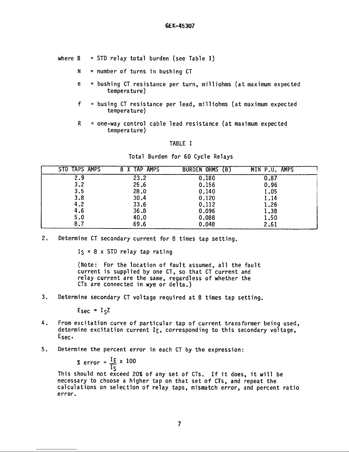
where
STD
B
N
e
f
R
TAPS
2.9
3.2
3.5
3.8
4.2
4.6
5.0
8.7
STD
=
number
bushing
busing
one-way
AMPS
relay
of
total
turns
CT
tempera
CT
ture)
resistance
temperature)
control
temperature)
Total
X
8
burden
in
resistance
cable
Burden
TAP
AMPS
23.2
25.6
28.0
30.4
33.6
36.8
40.0
69.6
(see
bushing
per
per
lead
TABLE
for
Table
CT
turn,
lead,
resistance
I
60
Cycle
BURDEN
I)
milliohms
milliohms
Relays
OHMS
0.180
0.156
0.140
0.120
0.112
0.096
0.088
0.048
(at
(B)
(at
maximum
maximum
(at
maximum
MIN
expected
expected
expected
P.U.
0.87
0.96
1.05
1.14
1.26
1.38
1.50
2.61
AMPS
2.
3.
4.
5.
Determine
(Note:
current
relay
CTs
Determine
Esec
From
excitation
determine
Esec.
Determine
%
should
This
necessary
calculations
error.
CT
=
8
are
secondary
=
excitation
the
error
to
secondary
x
STD
For
is
current
connected
IZ
curve
percent
1
E
=
Is
not
exceed
choose
on
selection
relay
the
supplied
are
CT
of
current
error
100
X
a
higher
current
tap
location
by
the
in
voltage
particular
20%
of
same,
wye
in
of
for
rating
of
one
CT,
or
required
corresponding
IE.
each
any
tap
on
relay
times
8
fault
so
regardless
delta.)
tap
by
CT
of
set
that
taps,
tap
assumed,
that
at
8
of
current
the
CTs.
set
of
mismatch
setting.
all
current
CT
of
whether
times
tap
transformer
this
to
expression:
it
If
CTs,
error,
the
and
the
setting.
secondary
does,
and
fault
it
repeat
and
being
will
the
percent
used,
voltage,
be
ratio
7
Page 8
GE:K-45307
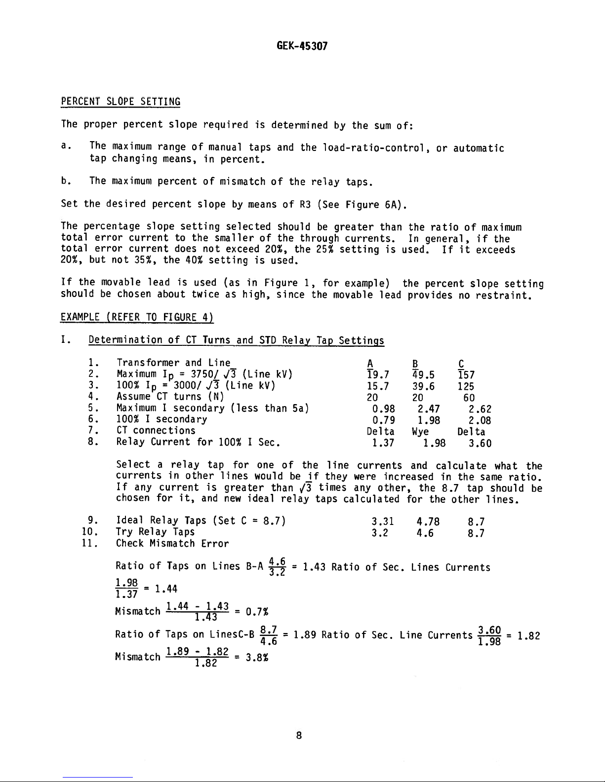
PERCENT
The
proper
a.
The
tap
The
b.
Set
the
The
percentage
total
total
20%,
If
should
error
error
but
the
be
EXAMPLE
I.
Determination
1.
2.
3.
4.
5.
6.
7.
8.
SLOPE
percent
maximum
changing
maximum
desired
not
movable
chosen
(REFER
Transformer
Maximum
100%
Assume
Maximum
100%
CT
Relay
SETTING
range
means,
percent
percent
slope
current
current
the
35%,
lead
about
TO
FIGURE
I
=
Ip
CT
I
secondary
I
connections
Current
slope
of
setting
the
to
does
40%
is
used
twice
of
CT
and
=
3750/
3000/
turns
secondary
required
manual
in
of
slope
smaller
not
setting
4)
Turns
Line
J
(N)
for
taps
percent.
mismatch
by
means
selected
exceed
in
(as
as
high,
and
(Line
J3
(Line
(less
I
100%
is
determined
of
of
20%,
is
used.
Figure
since
STD
kV)
kV)
than
Sec.
and
the
of
should
the
the
Relay
5a)
by
the
load—ratio-control,
relay
R3
through
1,
the
(See
be
25%
for
Tap
taps.
Figure
greater
currents.
setting
example)
movable
Settings
the
sum
than
lead
A
19.7
15.7
20
0.98
0.79
Delta
1.37
6A).
is
of:
the
In
used.
the
provides
B
49.5
39.6
20
Wye
ratio
general,
percent
2.47
1.98
1.98
or
If
automatic
of
maximum
if
it
exceeds
slope
no
restraint.
C
157
125
60
2.62
2.08
Delta
3.60
the
setting
10.
11.
9.
Select
currents
If
any
chosen
Ideal
Try
Relay
Check
Ratio
1.98
-
—
1.37
Mismatch
Ratio
Mismatch
a
relay
in
current
for
it,
Relay
Taps
Mismatch
of
Taps
1.44
1.44
of
Taps
1.89
other
Taps
on
-
on
-
1
tap
lines
is
and
(Set
Error
Lines
43
LinesC-B
1.82
8
for
greater
new
C
=
=
one
would
ideal
B-A
0.7%
-!.j-
3.8%
8.7)
than
relay
of
the
line
be
if
they
times
V3
taps
=
1.43
1.89
Ratio
=
calculated
Ratio
currents
were
any
3.31
3.2
of
of
Sec.
increased
other,
Sec.
Line
and
for
4.78
Lines
the
the
4.6
Currents
calculate
in
the
8.7
other
Currents
tap
8.7
8.7
same
should
lines.
what
=
the
ratio.
be
1.82
8
Page 9
GE
K—45
307
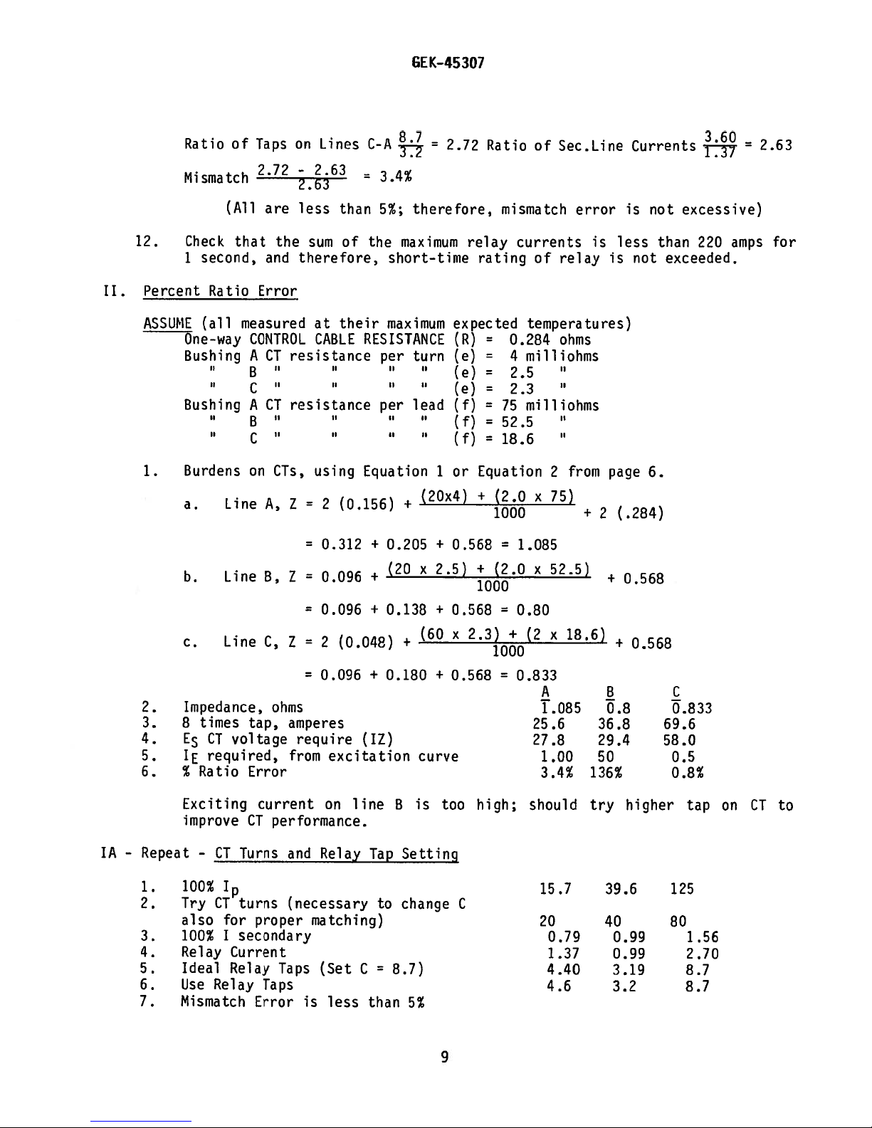
II.
12.
Percent
ASSUME
1.
Ratio
Mismatch
(All
Check
second,
1
Ratio
(all
One-way
Bushing
Bushing
II
Burdens
Line
a.
b.
Line
c.
Line
of
Taps
2.72
are
that
and
Error
measured
CONTROL
A
CT
B
C
A
CT
B
on
A,
3,
C,
on
-2.63
less
the
sum
therefore,
resistance
resistance
II
CTs,
Z
=
=
Z=0.096
=
Z
Lines
than
of the
their
at
CABLE
Ii
using
(0.156)
2
0.312
0.096
2
(0.048)
C-A
=
5%;
therefore
1
maximum
short-time
maximum
RESISTANCE
per
turn
II
II
II
per
lead
II
II
II
II
Equation
+
0.205
+
(20x2.5)
+
0.138
+
+
1
(20x4)
+
+
(60
2.72
relay
rating
expected
(R)
Ce)
(e)
Ce)
(f)
(f)=525
(f)
or
Equation
+
0.568
+
1000
0.568
x
2.3)+(2
Ratio
mismatch
=
0.284
=
4
2.5
=
2.3
=
75
=
18.6
(2.0
1000
=
(2.0
of
Sec.Line
currents
of
relay
temperatures)
ohms
rnilliohms
niilliohms
2
from
x
75)
1.085
x
52.5)
0.80
x
18.6)
error
is
+
page
2
+
is
less
is
(.284)
0.568
+
Currents
not
than
not
exceeded.
6.
0.568
excessive)
220
=
amps
2.63
for
2.
3.
4.
5.
6.
IA-Repeat
1.
2.
3.
4.
5.
6.
7.
Impedance,
times
8
E
5
CT
required,
JE
%
Ratio
Exciting
improve
—
CT
tap,
voltage
Error
current
CT
Turns
ohms
performance.
100%
Try
also
turns
CT
for proper
100%1secondary
Relay
Ideal
Use
Mismatch
Current
Relay
Relay
Taps
Taps
Error is
=
0.096
amperes
require
from
excitation
on
Relay
and
(necessary
matching)
(Set
less
line
C
+
(IZ)
Tap
than
0.180
to
B
Setting
change
8.7)
5%
curve
is
+
too
9
0.568
C
high;
0.833
A
T.o85
25.6
27.8
1
.00
3.4%
should
15.7
20
0.79 0.99
1.37
4.40
4.6
B
0.8
36.8
29.4
50
136%
try
39.6
40
0.99
3.19
3.2
higher
C
0.833
69.6
58.0
0.5
0.8%
125
80
tap
1.56
2.70
8.7
8.7
on
CT
to
Page 10
GEK-45307
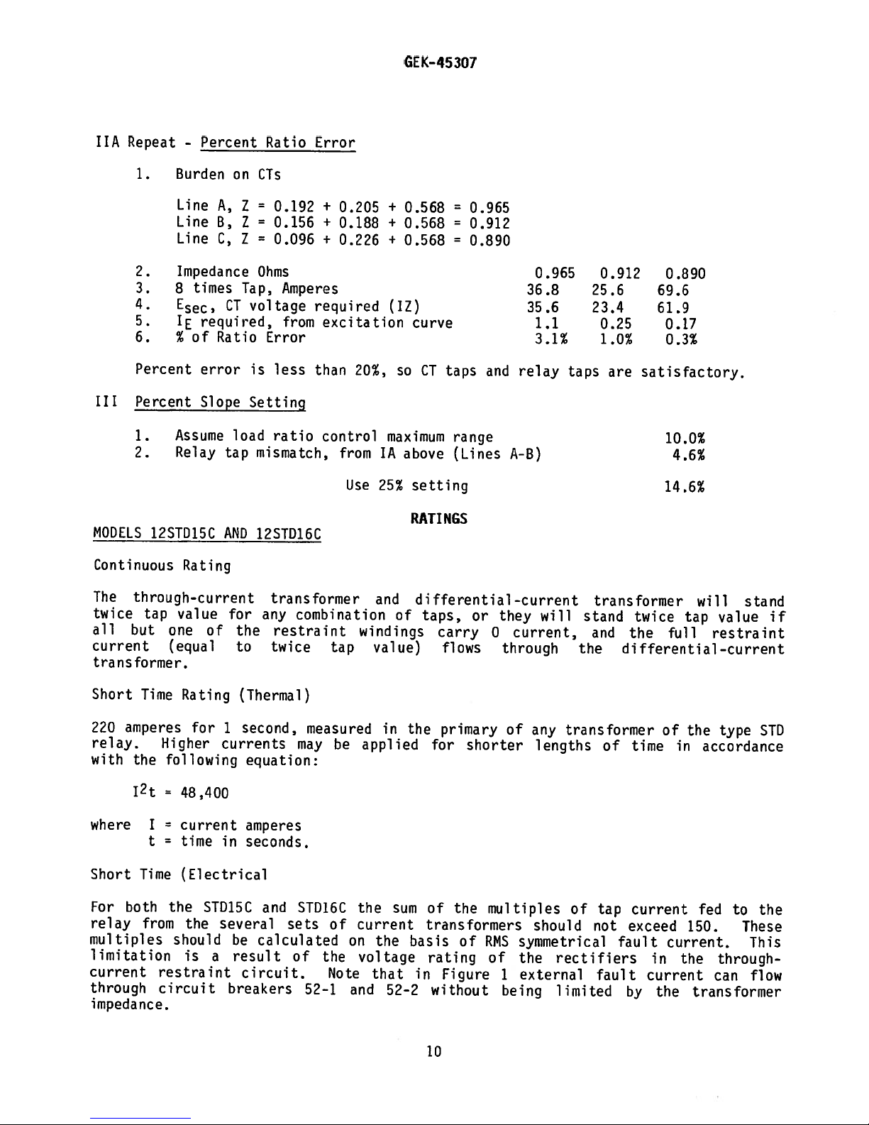
Repeat
hA
1.
2.
3.
4.
5.
5.
Percent
III
Percent
1.
2.
MODELS
-
Percent
Burden
Line
Line
Line
Impedance
times
8
required,
‘C
of
%
error
Slope
Assume
Relay
12STD15C
on
A,
B,
C,
CT
Ratio
load
tap
AND
Ratio
CTs
Z
=
0.192
0.156
Z
7
=
0.096
Ohms
Tap,
voltage
Error
is
less
Setting
ratio
mismatch,
12STD16C
Error
+
+
+
Amperes
required
from
excitation
than
control
0.205
0.188
0.226
20%,
from
Use
+
0.568
+
0.568
+
0.568
(17)
curve
so
maximum
IA
above
setting
25%
RATI
CT
=
=
=
taps
range
(Lines
NGS
0.965
0.912
0.890
and
36.8
35.6
relay
A-B)
0.965
1.1
3.1%
taps
0.912
25.6
23.4
0.25
1.0%
are
0.890
69.6
61.9
0.17
0.3%
satisfactory.
10.0%
4.6%
14.6%
Continuous
The
through-current
twice
all
tap
but
current
transformer.
Short
220
Time
amperes
relay.
with
the
where
Short
For
relay
Time
both
from
multiples
limitation
current
through
i
peda
in
n
one
(equal
Higher
following
=
=
=
t
the
restraint
circuit
ce.
Rating
value
of
Rating
for
48,400
current
time
(Electrical
STD15C
the
should
is
a
for
the
to
(Thermal)
second,
1
currents
equation:
amperes
in
seconds.
several
be
result
circuit.
breakers
transformer
any
combination
restraint
twice
may
and
STD16C
sets
calculated
of
52—1
tap
measured
be
of
on
the
Note
and
and
of
windings
value)
in
applied
the
sum
current
the
voltage
that
52—2
differential-current
taps,
carry
or
they
0
flows
the
primary
for
shorter
of
the
multiples
transformers
basis
in
rating
Figure
of
RMS
of
without
will
current,
through
of
any
lengths
should
symmetrical
the
external
1
being
transformer
stand
and
the
transformer
of
of
tap
not
rectifiers
fault
limited
will
twice
the
full
tap
value
restraint
differential—current
the
time
current
exceed
fault
by
of
in
current.
in
current
the
type
accordance
fed
150.
the
through—
can
transformer
stand
to
These
if
STD
the
This
flow
Page 11
GEK—45
307
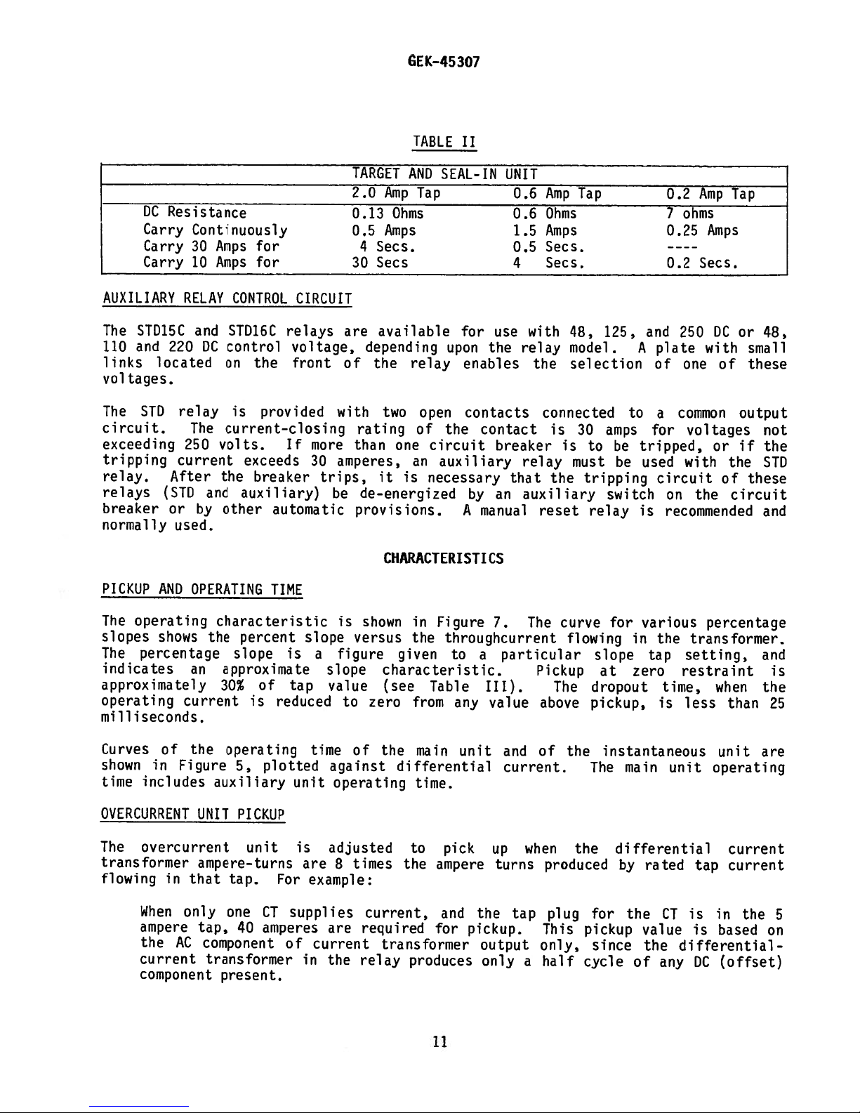
DC
Resistance
Carry
Carry
Carry
AUXILIARY
STD15C
The
and
110
links
220
located
voltages.
STD
The
circuit.
exceeding
tripping
relay.
relays
breaker
After
(STD
or
normally
Continuously
Amps
30
Amps
10
RELAY
and
DC
relay
The
volts.
250
current
the
and
by
other
used.
for
for
CONTROL
STD16C
control
on
the
is
CIRCUIT
relays
voltage,
front
provided
current—closing
If
exceeds
breaker
auxiliary)
automatic
more
30
trips,
TARGET
2.0
0.13
0.5
30
are
depending
of
with
rating
than
amperes,
de-energized
be
provisions.
AND
Amp
Ohms
Amps
Secs.
Secs
available
the
relay
two
one
it
is
TABLE
SEAL-IN
Tap
upon
open
of
the
circuit
an
auxiliary
necessary
II
for
the
enables
contacts
contact
by
A
manual
UNIT
0.6
0.6
1.5
0.5
4
use
relay
breaker
relay
that
an
auxiliary
Amp
Ohms
Amps
Secs.
Secs.
with
the
connected
is
the
reset
Tap
4S,
model.
selection
30
is
to
must
tripping
relay
125,
to
amps
be
be
switch
0.2
7
0.25
0.2
and
250
plate
A
of
common
a
for
tripped,
used
circuit
on
is
recommended
Amp
ohms
Amps
Secs.
with
one
voltages
or
with
the
DC
of
of
Tap
or
small
these
output
if
the
these
circuit
48,
not
the
STD
and
PICKUP
The
slopes
The
indicates
AND
operating
shows
percentage
OPERATING
an
approximately
operating
current
milliseconds.
Curves
shown
time
OVERCURRENT
The
transformer
flowing
of
the
in
Figure
includes
overcurrent
in
that
When
only
UNIT
ampere-turns
ampere
the
AC
current
component
characteristic
the
percent
slope
approximate
30%
operating
5,
auxiliary
PICKUP
tap.
one
tap,
40
component
transformer
present.
of
is
plotted
unit
CT
amperes
TIME
is
tap
reduced
unit
is
For
supplies
of
is
slope
a
figure
slope
value
time
against
operating
adjusted
are
8
example:
are
current
in
the
CHARACTERISTI
shown
versus
given
characteristic.
(see
to
zero
of
the
differential
times
the
current,
required
transformer
relay
in
Figure
the
throughcurrent
Table
from
main
time.
to
pick
ampere
and
for
produces
to
any
unit
pickup.
Cs
7.
a
III).
value
up
turns
the
output
only
The
particular
Pickup
above
and
of
current.
when
produced
tap
This
only,
half
a
curve
The
plug
flowing
slope
dropout
pickup,
the
The
the
for
pickup
since
cycle
various
for
in
the
tap
zero
at
time,
is
instantaneous
main
differential
rated
by
the
CT
value
the
of
any
percentage
transformer.
setting,
restraint
less
unit
operating
tap
is
is
differential
DC
when
than
unit
current
current
in
based
(offset)
the
and
is
the
25
are
5
on
11
Page 12
GEK—45
307
If
tap
ratio
matching
rating
magnetizing
that
it
is
unit
the
recommended
increasing
raised,
the
following
E
where
=
E
P
=
PERCENTAGE
The
percentage
restraint
differential
restraining
currents.
be
unbalanced
(as
shown
on
through-fault
transformers
currents
become
operation
currents,
as
Settings.
taps
on
a
self-cooled
inrush.
may
pick
that
the
pickup
requirements
equation:
20
-
(2.5)
CT
error
Pickup
current
of
overcurrent
DIFFERENTIAL
differential
circuits.
current
circuit
the
in
For
by
Figure
a
relay
certain
currents.
and
cause
unbalanced.
by
the
unbalanced
previously
chosen
are
If
of
up,
the
on
CT
especially
CT
the
currents
overcurrent
CT
(P-8)
in
percent,
CHARACTERISTICS
In
addition
of
that
the
to
line
is
operate,
minimum
7).
This
their
characteristic
ratios
currents
described
that
so
basis,
are
ratio
error
or
will
at
multiples
in
characteristics
to
the
current
indirectly
the
percentage,
High
currents
to
Percentage
caused
under
rated
the
overcurrent
greater
small
on
relay
unit.
be
more
pickup
of
operating
transformers,
energized
current
is
change,
restraint
by
Determination
CT
current
than
transformer
tap
setting
If
stringent,
of
the
tap
setting.
are
circuit,
transformer
determined
necessary
saturate
with
imperfect
unit
tap
the
overcurrent
overcurrent
provided
the
by
the
the
is
of
is
rating,
banks.
be
increased,
in
which
relay
the
secondary
by
the
to
prevent
cores
result
also
matching
Turns
CT
not
greater
will
not
there
If
setting
accordance
unit
by
through—current
is
energized
is
equipped
transformer
relay
false
of
that
required
of
and
pick
this
rather
currents
slope
the
the
to
the
STD
than
up
is
danger
happens,
must
with
by
with
secondary
must
setting
operation
current
secondary
prevent
secondary
Relay
the
on
than
be
the
the
a
Tap
HARMONIC
At
that
time
the
establishes
inrush,
This
cause
Power
causes
false
system
component.
constant
cycle
at
Transformer
exciting
magnitude,
full-load
of-circuit
of
sharply
practically
illustrated
RESTRAINT
power
a
the
and
in
the
an
unbalance
operation
fault
The
sine
circuit
which
fault
magnetizing-inrush
impedance
occasionally
current
closure
peaked
no
current
in
Figure
CHARACTERISTICS
transformer
required
primary
flux
winding
current
if
means
currents
waveform
impedance.
occurs,
were
are
results
The
and
resulting
having
for
worst
the
on
half-cycle
voltage
during
conditions
loops
the
8.
is
of
DC
upon
currents
from
RMS
an
wave.
opposite
energized,
in
the
flows
to
flow
not
a
nearly
from
component
circuit
core
value
of
of
core.
only
in
provided
pure
sinusoidal
vary
saturation.
power
They
current
half
current
This
through
the
to
sine
depends
impedance
according
with
100%
transformer
have
on
cycles.
current
differential
prevent
waveform,
voltage
magnitude
offset,
a
very
one
is
the
it.
on
to
They
distorted
side
The
supplied
is
current
generation
the
the
approaching
residual
of
two
called
relay,
plus
time
and
extremely
are
waveform
the
current
to
the
magnetizing
transformers.
which
DC
a
and
in
the
angle.
often
flux
and
zero
axis,
waves
primary
would
transient
nearly
voltage
variable
of
times
16
point-
made
high
up
and
are
12
Page 13
GEK—45307
current
Any
of
one
DC
a
of
component
the
frequencies
relative
magnitudes
fundamental
fault-current
while
The
afford
wave.
the
high
an
In
fundamental
are
passed
component
the
magnetizing-inrush—
auxiliary
slight
waves
momentary
in
predetermined
wave),
this
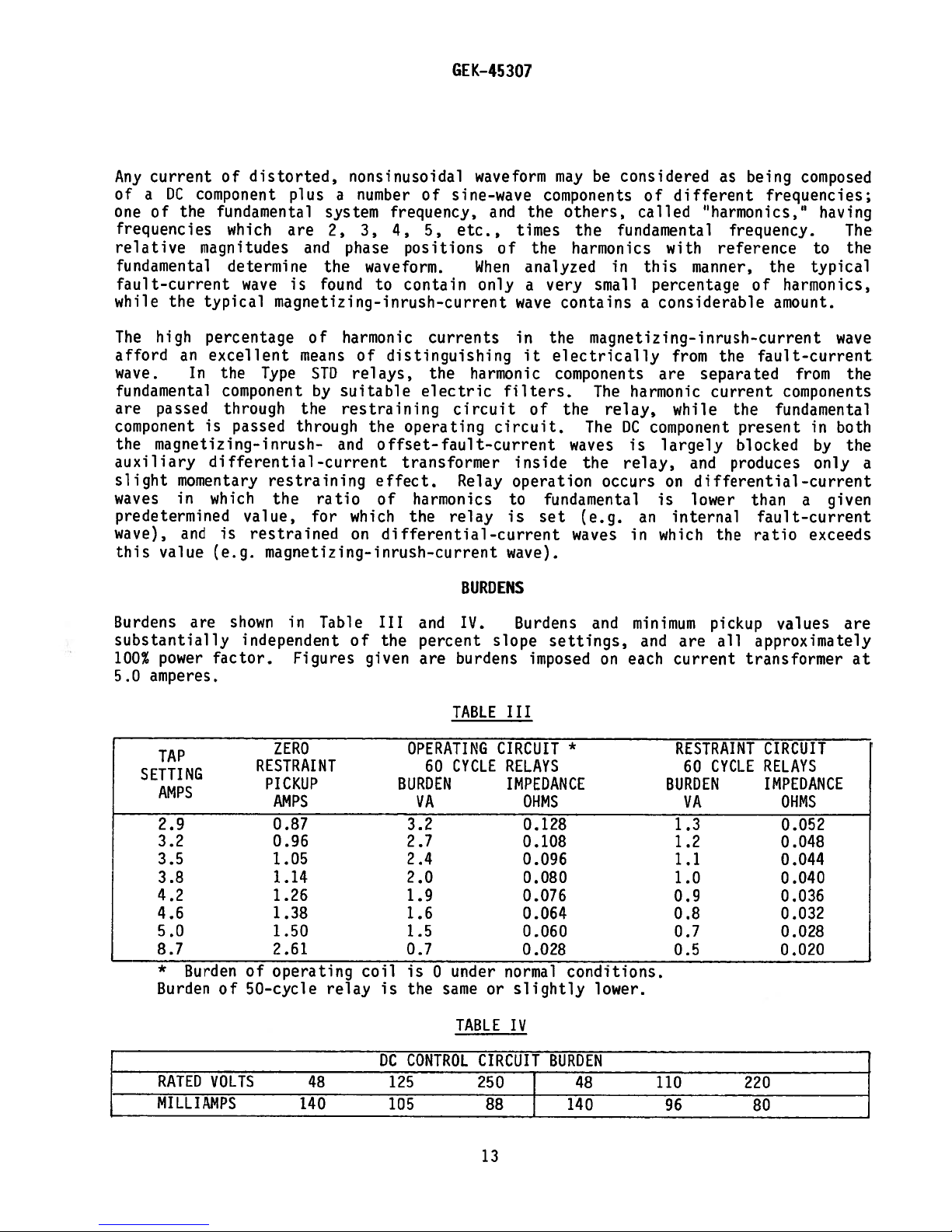
Burdens
and
value
are
substantially
power
100%
5.0
amperes.
distorted,
of
plus
fundamental
which
are
and
determine
wave
typical
is
magnetizing-inrush—current
percentage
excellent
the
means
Type
component
through
is
passed
the
through
differential-current
restraining
which
the
value,
is
restrained
(e.g.
magnetizing-inrush—current
shown
in
independent
factor.
Figures
system
2,
the
found
of
STD
by
ratio
for
Table
a
phase
harmonic
suitable
restraining
and
nonsinusoidal
number
of
frequency,
3,
4,
5,
positions
waveform.
to
contain
currents
of
distinguishing
relays,
the
electric
the
operating
offset-fault—current
transformer
effect.
of
harmonics
which
on
of
the
differential—current
III
and IV.
the
percent
given
are
waveform
sine-wave
and
etc.,
of
When
only
harmonic
circuit
circuit.
Relay
relay
BURDENS
slope
burdens
the
times
the
analyzed
a
wave
in
it
filters.
of
inside
operation
to
is
set
wave).
Burdens
imposed
may
components
others,
harmonics
very
contains
the
electrically
components
the
waves
fundamental
waves
settings,
considered
be
of
called
the
fundamental
with
in
this
small
percentage
considerable
a
magnetizing-inrush—current
from
are
The
harmonic
The
the
relay,
DC
relay,
occurs
component
is
largely
on
while
is
(e.g.
and
internal
an
in
which
minimum
and
each
on
as
being
different
“harmonics,”
frequency.
reference
manner,
of
fault-current
the
separated
current
the
present
blocked
and
produces
differential-current
lower
than
fault—current
the
ratio
pickup
all
are
current
approximately
transformer
composed
frequencies;
having
to
typical
the
harmonics,
amount.
from
components
fundamental
in
by
only
given
a
exceeds
values
The
the
wave
the
both
the
a
are
at
TA
SETTIN
G
AMPS
2.9
3.2
3.5
3.8
4.2
4.6
5.0
8.7
*
Burden
Burden
RATED
MILLIANPS
of
of
50-cycle
VOLTS
ZERO
RESTRAINT
PICKUP
AMPS
0.87
0.96
1.05
1.14
1.26
1.38
1.50
2.61
operating
relay
48
140
coil
is
DC
125
105
TABLE
OPERATING
CYCLE
60
BURDEN
VA
3.2
2.7
2.4
2.0
1.9
1.6
1.5
0.7
under
is
0
the
same
TABLE
CONTROL
III
CIRCUIT
RELAYS
IMPEDANCE
OHMS
0.128
0.108
0.096
0.080
0.076
0.064
0.060
0.028
normal
or
slightly
IV
CIRCUIT
250
88
13
*
conditions.
lower.
BURDEN
48
140
RESTRAINT
CYCLE
60
BURDEN
VA
1.3
1.2
1.1
1.0
0.9
0.8
0.7
0.5
110
96
CIRCUIT
RELAYS
IMPEDANCE
OHMS
0.052
0.048
0.044
0.040
0.036
0.032
0.028
0.020
220
80
—
Page 14
Figure
Refer
identify
6
also
shows
the
to
parts
the
the
internal
internal
more
arrangement
connection
completely.
GEK—45307
CONSTRUCTION
the
of
diagrams,
components
Figures
10
of
and
the
STD15C
11,
which
relay.
will
CURRENT
In
one
and
In
each
windings
In
brought
The
block
TRANSFORMERS
Type
the
each
for
winding
Type
the
with
No.
both
relays
out
primary
arrangement.
(depending
through-current
connected
is
inserting
When
the
between
the
marked
the
fourth
terminals
terminal
winding
transformer
under
the
lead.
STD15C
relay,
line-current-transformer
No.2terminates
one
No.
relay,
primary
2
STD16C
only
I,
there
stud
to
circuit
5.
of
Two
whether
on
transformer
end
a
relay
6
and
corresponding
in
CT
and
to
tap
plugs
STD16C
circuit
6
1),
the
STD
that
tap
in
screw
the
at
there
No.
and
is
differential—current
a
each
of
or
relay
the
winding.
tap
the
used
is
is
connected
at
7
reconnected
which
relay.
gives
through-current
4.
stud
are
winding,
corresponding
3
these
three
transformers
horizontal
is
tap
blocks.
on
four-circuit
to
rear
the
to
connects
terminal
The
the
best
circuit.
three
and
Type
a
tap
A
of
stud
of
the
it
current
transformer
Winding
separate
each
to
rows
STD15C
the
on
the
through—current
applications,
7,
relay
the
upper
row
directly
on
match
has
No.
through—current
terminating
4
studs
6,
transformer
is
completed
of
tap
STD16C),
or
differential—current
jumper
the
and
to
for
the
should
tap
the
the
the
cradle
in
movable
primary
two
terminates
1
at
a
with
in
3
one
and
through
positions
one
restraint
shown
as
normally
be
block
differential-current
lead
should
current
windings,
at
transformers,
separate
order.
that
primary
special
a
provided
are
for
row
transformer
windings
in
Figure
connected
disconnected
(above
be
the
in
stud
stud,
lead
tap
each
the
row
placed
movable
6
by
1,
at
matching
are
moved
the
from
differential—current
restraint
recognized
but
quantity
RESTRAINT
bridge
rectifier
transformer.
in
so
one
windings
producing
of
parallel.
connections
both
on
transformer
permit
is
The
The
tap
taps
current
taps
tap
plug
through-current
should
It
current
current
energy,
be
transformer
transformer,
this
THROUGH-CURRENT
wave
full
A
current
units
restraint
are
connected
of
arranged
position
remains
that
also
restraint
CIRCUIT
unequal
are
constant.
pickup
through
some
receives
In
line—current
in
that
another
to
transformer
simultaneously
current
one
restraint.
so
small
is
the
STD16C
the
total
The
14
matching
of
output
output
flows
the
that
relay,
transformer
the
in
horizontal
a
winding
selected
not
primary
However,
it
may
the
of
is
secondary
only
windings
compared
be
secondary
the
directed
and
so
assumed
DC
secondary
row,
one
that
through
outputs
to
currents,
corresponding
of
the
differential-
the
of
the
to
to
of
each
of
the
percent
the
be
currents.
when
through—
percent
through-
operating
zero.
through
three
all
slope
a
Page 15

rheostat
rheostat,
through
state
(R3)
the
an
amplifier
located
percent
isolating
that
on
slope
transformer,
controls
the
front
may
be
the
telephone-type
GEK—45307
of
the
varied
rectified,
relay.
from
and
15%
directed
relay.
to
By
means
40%.
to
the
of
The
adjusting
output
sensitive
is
the
put
solid
DIFFERENTIAL-CURRENT
The
differential-current
directly;
series-tuned
parallel
by
a
The
reactor
to
offer
in
parallel
desired
operating
The
reactor
currents
R2
is
can
be
rectifier
the
restraint
It
will
sinusoidal
hence
contains
from
operating
ThyriteR
A
transformer
the
rectifiers
characteristics
2)
resonant
full—wave
series
(Li)
high
on
amount
circuit
parallel
(L2)
of
harmonic
connected
adjusted
is
be
and
cause
more
resistor
limits
the
circuit;
bridge
resonant
that
impedance
the
of
that
in
to
paralleled
circuit
evident
of
the
relay
than
by
and
of
operating
filter.
are
AC
operate
of
resonant
are
parallel
give
system
a
the
any
the
CIRCUIT
transformer
(tripping)
and
3)
The
prior
circuit
tuned
side
to
to
currents
of
current.
the
sense
trap
tuned
frequencies
the
desired
with
of
the
that
if
frequency,
to
yield
certain
harmonic
connected
momentary
capacitors
relay.
the
harmonic
operating
to
being
is
pass
the
amplifier.
is
to
block
to
on
the
the
sense
the
an
percentage
currents
across
high—voltage
from
secondary
signal
restraint
and
supplied
made
up
currents
of
other
operate
made
The
rectifier,
output
of
fundamental
pass
with
AC
side
of
amount
of
through-current
amplifier.
differential
it
will
flow
output.
of
harmonics,
flowing
the
damage,
supplies
to
the
restraint
to
the
of
a
5
of
the
frequencies.
of
a
15
relatively
the
harmonic
restraint
current
mostly
If,
however,
in
secondary
peaks
without
solid—state
isolating
sensitive
microfarad
fundamental
and
the
rectifier
microfarad
frequency
harmonic
restraint.
in
the
the
restraint
of
which
1)
the
currents
Resistor
can
be
currents
little
restraint
currents
applied
the
the
relay
the
may
occur,
materially
instantaneous
amplifier
transformer
are
each
sense
capacitor
capacitor
system
adjusted
is
amplifier.
(Cl)
frequency
Ri
is
to
applied
(C2)
while
impedance.
rectifier,
The
output
and
applied
to
the
operating
circuit
differential
will
be
restrained
circuit.
differential-current
thus
protecting
affecting
unit
through
through
rectified
and
connected
give
to
and
allowing
Resistor
of
relay
and
circuit
the
a
a
a
and
the
the
a
and
the
to
is
OVERCURRENT
The
instantaneous
indicator.
complete
indicated
Because
is
possible
current
restraint
would
main
supply.
unit
UNIT
On
the
trip
that
tripping
of
saturation
that
transformer
will
As
may
unit
extremely
circuit.
less
than
be
provided
result,
a
be
falsely
is
heavy
was
of
the
operating
the
a
hinged—armature
internal
The
instantaneous
through
CTs
the
and
currents
percentage
than
under
the
conditions
restrained.
fault
instantaneous
relay
transformers
will
slope
actual
Tripping
15
relay
currents,
unit
be
tap
harmonic
of
a
with
target
unit.
provided
would
content
high
is
a
this
at
high
imply,
internal
assured,
self—contained
unit
will
will
be
fault
from
the
and
of
the
fault
however,
target
pick
up
exposed,
currents,
differential—
more
fault
harmonic
current
current,
by
and
to
it
the
the
Page 16

GEK—45307
overcurrent
produced
of
pickup
MAIN
The
output
10
components
printed
schematic
leaving
The
too,
by
and
OPERATING
primary
controls
and
11
mounted
circuit
of
the
telephone-type
has
been
attention.
ADJUSTMENTS.
TARGET
There
has
its
AND
is
SEAL-IN
a
coil
target
telephone—type
unit
contacts.
button
operates,
The
beneath
unit
operation.
maximum
speed
UNIT
functioning
a
a
as
card
this
factory,
carefully
this
If
in
series
relay.
raising
target
the
magnetizing
of
operation
simple
large
on
a
is
card
is
and
relay
small
UNIT
and
seal-in
and
When
its
of
lower
Pickup
unit
telephone
rectangle.
printed
installed
shown
should
is
mounted
adjusted
relay
its
target
this
left
inrush
of
the
of
relay.
circuit
in
require
at
has
unit
mounted
contacts
the
telephone—type
into
unit
corner
is
set
current.
the
main
STD
The
in
a
Figure
no
vertically
the
been
view
will
of
the
above
unit
relay
The
amplifier
card
ten-prong
9.
further
factory,
disturbed,
on
in
parallel
and
remain
cover
and
is
sense
in
This
in
the
relay
exposed
of
the
level
Figure
the
a
amplifier
the
top
printed
component
attention.
mid-section
the
and
top
left
with
sealing
the
shows
5
overcurrent
solid-state
consists
half
should
refer
of
the
contacts
around
until
relay
of
differential
of
card
is
to the
the
main
released
case.
the
is
of
the
design
adjusted
of
require
relay.
close,
the
relative
unit.
amplifier,
shown
many
in
electronic
relay.
socket.
the
relay.
no
section
contacts
the
telephone-type
by
current
levels
whose
Figures
prior
further
under
This
of
seal-in
pushing
This
A
to
It,
unit
the
a
CASE
The
case
hardware
the
target
cover
The
The
screw
case
electrical
through
blocks,
The
outer
and
the
The
relay
complete
firmly
the
case.
in
the
connection
The
cover,
in
place.
draw
To
Shorting
is
suitable
is
provided
reset
has
provision
studs
has
connections
spring—backed
between
which
block,
inner
block
mechanism
unit,
in
case
the
The
with
case
case
upside
between
which
out
the
bars
are
for
for
mechanism
or
contact
rests
attached
has
is
all
by
a
and
down.
the
blocks
is
fastened
relay
provided
surface
either
for
screw
to
terminals
mounted
leads
latch
cradle
unit,
or
method.
for
the
sealing
a
connections
between
fingers
removable
a
the
case,
for
in
terminating
at
the
are
The
of
the
the
to
the
in
the
semi-flush
The
trip
wire.
at
the
mounted
connecting
holds
the
steel
a
top
so
constructed
connecting
cradle
case
cover
case
to
cover
indicator
the
relay
the
internal
framework
the
at
and
and
by
thumbscrews,
is
short
panel
attaches
bottom
unit
in
stationary
studs
connections.
inner
bottom
that
plug,
case,
removed
the
mounting,
to
instantaneous
and
the
for
the
and
plug
that
for
the
called
block.
and
the
a
guide
relay
besides
also
locks
holds
and
the
current-transformer
and
the
external
case
molded
completes
external
the
This
pin
cannot
making
the
the
plug
an
assortment
case,
studs
inner
cradle,
cradle
at
the
latch
connecting
is
and
carries
unit.
connections.
are
and
outer
the
circuit.
connections,
and
is
the
back
be
inserted
electrical
in
place.
drawn
circuits
of
Each
made
is
held
of
plug
out.
a
16
Page 17

(see
drawn
Figure
out.
12).
The
latches
are
GEK-45307
then
released
and
the
relay
unit
can
be
easily
separate
A
relay
in
sources.
tested
These
in
relays,
cartons
relay,
examine
resulting
transportation
Office.
Reasonable
the
parts
If
the
relays
original
Foreign
cover
matter
is
Immediately
made
to
make
calibrations
testing
place
Or,
the
designed
from
care
may
cartons
removed,
upon
sure
are
plug
on
the
the
relay
laboratory.
when
to
it
rough
company
should
be
injured
not
are
in
collected
and
receipt
that
unchanged.
not
protect
for
a
cause
can
panel,
unit
RECEIVING.
included
any
handling
and
exercised
be
or
to
be
place
on
of
the
relay
be
either
can
them
damage
promptly
the
installed
that
the
trouble
the
inserted
from
drawn
be
HANDLING
as
part
against
sustained
is
evident,
notify
in
adjustments
is
free
outside
in
the
ACCEPTANCE
relay,
has
an
not
in
place
its
own
out
and
AND
of
a
damage.
in
file
the
unpacking
disturbed.
immediately,
from
of
the
case
operation
TESTS
inspection
been
damaged
of
the
source
replaced
STORAGE
control
Immediately
transit.
damage
a
nearest
the
they
moisture,
may
of
connecting
panel,
relay,
find
the
and
in
shipment
current,
of
by
another
If
claim
General
in
should
dust
and
its
relay.
acceptance
will
upon
order
be
way
and
plug
injury
at
stored
metallic
inside
to
or
which
be
receipt
once
Electric
that
test
that
test
from
has
shipped
or
with
none
in
when
should
the
the
other
been
of
damage
the
Sales
their
chips.
the
be
relay
in
a
of
VISUAL
Check
INSPECTION
the
calibration
Remove
broken
screws
the
or
are
frIECHANICAL
Check
manually,
Check
in
the
the
to
the
section
ELECTRICAL
It
receipt
recommended
is
of
nameplate
range
of
relay
cracked
tight.
INSPECTION
operation
see
that
contact
gap
on
SERVICING.
TESTS
the
relay.
the
from
molded
of
that
stamping
relay
its
parts,
the
they
wipe
and
the
make
to
received
case
and
or
telephone-type
operate
of
smoothly,
these
following
check
other
sure
agree
signs
relay
units,
electrical
17
with
by
that
visual
of
and
without
which
the
the
requisition.
inspection
physical
instantaneous
noticeable
should
tests
model
agree
be
number,
damage,
made
that
and
overcurrent
friction
with
immediately
rating
there
values
or
that
are
binds.
given
upon
and
no
all
unit
Page 18

1.
2.
3.
4.
Test
In
1.
2.
3.
4.
5.
6.
Minimum
Minimum
A
single
A
slope
Equipment
order
Two
Three
A
test
Figure
One
Two
A
double-pole
single
expected
to
facilitate
load
ammeters
rectifier
13.)
indicating
single-pole
pickup
pickup
check
check
boxes
of
main
of
the
point
on
point
to
be
used.
tests,
for
regulating
(two
AC
for
checking
lamp
double—throw
single-throw
operating
instantaneous
the
harmonic
on
the
slope
the
following
the
and
one
the
switch
line
GEK—45307
unit.
overcurrent
restraint
characteristic
test
DC)
for
relays
selectors
switch.
test
equipment
currents
measuring
response
unit.
characteristic.
curve,
is
the
test
the
to
for
the
recommended:
currents
second
harmonic.
approximate
(See
Check
During
through
relay
should
0.96
Figure
has
For
flowing
tap
be
this
set
pick
amperes.
14;
operated.
an
additional
in
position.
made.
one
protective
is
entirely
inrush
With
or
the
restraint,
The
instantaneous
through
Check
the
through—current
PROCEDURE.
the
pickup
test,
restraint
with
up
the
terminals
The
relays,
adequate
severe
selector
as
described
5-6
the
25%
a
at
30%
A
source
indicating
pickup
If
the
pickup
but
fault
overcurrent
terminals.
of
selector
winding
slope
of
of
and
5
pickup
of
due
under
conditions.
switch,
in
restraint,
the
tap
and
DC
test,
6
the
to
the
The
main
rating,
power
lamp
and
is
all
ST,
unit,
switches
and
at
will
the
the
between
relay
the
in
section
unit
pickup
using
the
operate
the
2.9
1O%,
rated
at
provide
pickup
tap
plugs
1.35
has
relay
design
conditions,
the
on
should
should
as
described
(S2
the
and
connections
S4)
winding
ampere
or
the
voltage
signal,
a
ratio-matching
pickup
should
should
in
the
and
1.65
wider
A
position,
permissible
and
even
application,
during
INSTALlATION
be
checked
be
about
in
are
open,
only.
should
be
showing
be
1.5
amperes,
5
ampere
amperes,
variations
transformer
check
the
PROCEDURE.
by
passing
eight
the
times
section
shown
and
For
example,
taps,
be
between
connected
that
tap
and
no
adjustment
the
harmonic
a
tap
on
in
Figure
current
passes
with
the
main
0.78
shown
as
the
main
with
the
25%
current
slope
should
than
relay
accuracy
magnetizing
current
high
current
rating.
INSTALLATION
14.
a
unit
and
in
unit
most
TESTS
Before
final
outlined
placing
location,
for
this
the
to
relays
ensure
purpose.
INSTALLATION
in
service,
that
it
is
check
correct.
PROCEDURE
the
relay
18
The
calibration
following
to
test
be
used
procedure
in
its
is
Page 19

The
R3.
settings.
restraint,
repeated
Best
is
PICKUP
The
test
given
Pickup
the
tap
operation
within
successive
setting
made
are
should
plugs
0.01
should
Relay
Changes
results
only
circuit
for
should
checks.
calibration
made
In
the
and
through—current
until
a5ampere
be
in
ampere
not
after
for
1.5
the
can
be
be
no
5
repeated
If
in
any
event
further
be
obtained
the
pickup
rated
(0.3)
(1.0)
with
pickup
disturbed.
is
accomplished
one
one
other
is
shown
relay.
amperes
ampere
several
the
is
GEK—45307
of
these
setting
restraint
deviation
if
two
settings
in
with
position,
total
found
CAUTION
by
resistors
is
from
the
through-current
Figure
Those
current
times,
pickup
to
be
adjusting
changed,
adjustment
proper
are
correct.
14,
in
(
flowing
and
25%
until
current
from
)
1.35
will
with
are
slope
two
resistors
affect
the
procedures
calibration
restraint
S?
open.
for
a
in
terminals
tap
successive
being
to
1.65
the
pickup,
ampere
1
setting.
interrupted
(0.27
Ri,
R2
other
harmonic
should
is
adjustment
first
The
rated
5
readings
to
and
two
noted.
and
The
0.33),
be
values
relay.
and
6,
pickup
agree
between
the
DC
With
the
telephone-type
This
verify
Before
and
when
adjust
If
amplifier
HARMONIC
The
with
with
slope
The
fixed
negligible
typical
principal
second
for
passed
rectified
current
voltage
that
Ri
pin
viewed
Ri
the
harmonic
suitable
S2
taps.
analysis
percentages
harmonic
controlled
a
current
control
may
the
is
adjusted
8
pickup
CURRENT
closed
transformer
to
of
(+)
from
for
card
restraint
ammeters
of
percentages
components
current,
fundamental
voltage
relay
be
amplifier
the
the
a
voltage
is
not
obtain
to
RESTRAINT
to
position
a
single-phase
of
inrush
is
fixed,
amount
is
added
and
applied
for
sense
card
and
DC,
of
are
thus
current.
applied
can
has
pickup,
amplifier
input
in
limits
the
is
adjusted
load
P.
fundamental,
all
current,
DC,
the
of
in
phase
provides
the
to
be
used
as
shown
produced
put
socket
proper
fundamental,
overall
by-passed
to
the
with
boxes.
Tests
half-wave
higher
wiring
pickup
by
as
with
proper
as
an
in
an
a
card.
sense
this
means
The
should
and
even
seen
percentage
current
the
a
means
indication
Figure
output
DC
voltmeter
The
connections.
amplifier
setting,
value.
of
test
be
rectified
second
harmonics.
at
and
second
fundamental
of
terminals
15,
signal.
pins
Test
a
circuit
made
harmonic
the
relay
may
of
fundamental
varying
of
of
operation
and
(one
are
counted
card
then
Rectifier
the
on
current
This
terminals,
harmonic.
be
varied
component
the
the
the
volt
Apply
of
0.430
adjust
is
as
5.0
shows
components,
closely
frequency.
ratio
relay,
of
indicating
scale)
from
pickup
to
P1
used
shown
(1.0)
the
inasmuch
Although
by
providing
of
second
of
the
pickup
the
amplifier.
lamp
on
pin
right
on
in
in
ampere
approximates
the
to
current
0.470
the
conjunction
Figure
and
presence
well
as
as
percent
the
a
The
half-wave
harmonic
will
2
left
volts.
sense
path
of
(-)
and
15,
25%
of
as
a
its
by
19
Page 20

The
the
following
DC
component,
expression
and
the
shows
by-pass
the
current.
GE
K-45
relationship
307
between
the
percent
second
harmonic,
Second
%
Figure
harmonic
set
The
properly
will
set
contacts
1.1)
2%
a
should
influenced
sure
If
harmonic
adjusting
16
at
4.0
relay
operate
at
amperes.
tolerance
be
it
Harmonic
is
derived
corresponding
(0.8)
is
calibrated
set,
the
with
4.0
(0.8)
with
gradually
This
at
noted
by
the
is
maintained
restraint
rheostat
section.)
THROUGH-CURRENT
The
through-current
percent
using
I
reads
the
slope
the
characteristics,
circuit
differential
currents.
=
0.4511
from
to
amperes.
relay
second
amperes,
corresponds
the
set
that
the
application
at
is
R2.
RESTRAINT
restraint,
illustrated
0.212
+
the
various
with
a
will
harmonic
the
increasing
point
current
its
proper
found
(See
current
‘DC
0.51Dc
above
values
composite
restrain
equal
auxiliary
to
to
magnitude
of
by-pass
to
CAUTION
which
is
shown
in
Figure
100
expression.
of
with
to
bypass
19-21%
compensate
value.
be
out
gives
in
15,
and
13
by—pass
RMS
greater
20%
relay
current
second
in
current
of
at
the
Figure
with
reads
current
or
should
harmonic
for
normal
the
rectifier
(Ii)
adjustment,
beginning
relay
7.
S2
the
current
of
than
lower.
(‘i)
the
It
closed
It
shows
two
20%
just
at
(see
fluctuations
and
should
of
percentage
may
smaller
percent
the
for
(ii)
times
a
tap
second
With
the
DC
begin
value
a
Figure
of
16),
in
branch
it
may
be
(12)
checked
be
INSTALLATION
differential
checked
be
to
position
of
the
constant
value.
harmonic,
ammeter
to
close
4.5—5.5
providing
pickup.
is
slightly
to
corrected
PROCEDURES
adjusted
and
Ammeter
B.
two
through—
second
DC
When
but
(12)
its
(0.9—
It
make
by
or
r-
These
time,
overheated
NOTE:
direction.
set
In
testing
position
current
position,
indicated
positions.
the
adjustment
current
application
is
maintained
SLOPE
%
SETTING
40
25
15
currents
with
The
point
STD16C
and
tap
plugs
the
in
Table
If
magnitude
of
at
13
30
30
30
should
cooling
-
percent
This
value.
relays,
then
the
in
relay
V
one
any
may
be
in
differential
its
TABLE
AMPERES
12.0-13.2
7
8.3
.5-
4.5-
5.0
periods
is
to
other,
5.0
should
(VA).
of
made
the
through-current
proper
V
(11/13
be
permitted
slope
ensure
the
setting
thus
(1.0)
ampere
just
Repeat
these
made
current
value.
1RUE
—-
-
SLOPE
40.0—44.0
25.0—27.5
15
.0—16.5
between
tolerance
that
pick
with
set
points
by
(Ii)
-
x
100)
CAUTION
to
tests;
the
should
checking
position
up
the
adjusting
branch
and
flow
is
10%
slope
be
checked
all
and
for
values
percent
is
found
R3.
(13)
should
SLOPE
SETTING
40
25
15
for
only
otherwise,
of
characteristic
the
the
slope
be
to
It
is
be
TABLE
AIPERES
13
6
6
6
a
nominal,
with
restraint
percent
of
the
tap
other
should
slightly
checked
I
2.4-2.64
1
.5—1
0
.9—1
few
the
switch
set
VA
.66
.00
seconds
coils
all
never
coils.
slope
1j
in
than
be
influenced
to
make
TRUE
(1/3
40-44
25—27.5
15—16.5
S4
and
will
in
set
the
as
noted
SLOPE
at
the
falls
first
With
in
currents
13
25%
prescribed,
that
that
sure
X
100)
a
be
in
the
and
by
plus
below
one
the
40%
15%
the
the
it
20
Page 21

Any
pickup
any
set
with
change
and
adjustment
points
Table
in
R3
harmonic
of
must
III.
to
restraint.
minimum
then
give
be
the
pickup
rechecked,
desired
However,
will
to
GEK—45307
slope
after
change
make
the
sure
will
the
slope
slope
that
have
characteristics.
they
small
setting
are
effect
has
still
upon
once
in
minimum
been
set)
The
slope
accordance
INSTANTANEOUS
This
checked
unit
of
making
unit
by
is
passing
should
If
the
setting
the
unit
this
approximately
DROPOUT
After
in
OF
the
the
ACCEPTANCE
MAIN
other
LOCATION
The
location
well
lighted
MOUNTING
The
relay
dimensions
CONNECTI
should
are
ONS
OVERCURRENT
located
pick
is
and
at
high
a
up
at
incorrect,
turning
adjustment,
one
second
UNIT
tests
are
TESTS
should
to
shown
facilitate
be
mounted
in
be
UNIT
the
current
B
times
the
the
at
complete,
section.
clean
inspection
Figure
upper
it
current
a
on
may
cap
time.
and
a
18.
right-hand
of
the
be
screw
check
dry,
vertical
rated
tap
adjusted
should
and
rating)
until
free
testing.
side
frequency
not
the
dropout
from
surface.
as
by
the
be
dust
of
the
through
described
loosening
proper
allowed
of
and
The
relay.
pickup
the
excessive
outline
terminals
under
the
lock
to
flow
main
and
Its
setting
5
and
may
6,
CHARACTERISTICS.
nut
at
the
is
obtained.
for
more
unit,
as
described
vibration,
panel
drilling
he
The
top
In
than
and
Internal
diagrams
Of
course,
transformer
When
the
should
wire,
Every
the
shorter
every
brushes
main
brushes;
touches
main
brush.
are
be
or
its
circuit
current
are
the
connection
given
any
winding,
relay
is
permanently
equivalent.
in
brush
circuit
bent
otherwise
shorting
diagrams
in
Figures
through-current
provided
mounted
grounded
the
drawout
in
the
case,
or
other
high
enough
the
bar
before
on
1,
the
an
case
to
CT
are
and
2
transformer
taps
insulating
by
a
has
which
circuit
engage
secondary
the
circuit
shown
3
for
are
conductor
an
the
with
the
21
in
differential
properly
panel,
auxiliary
connecting
shorting
connecting
circuit
is
Figures
winding
chosen.
one
not
less
brush.
may
completed
10
applications.
may
of
than
plug
bars,
plug
be
from
and
be
the
(See
should
make
or
opened
steel
No.
the
11.
used
12
Figure
sure
test
plug
Typical
for
supporting
AWG
engage
plug
where
12.)
the
to
any
gage
first.
auxiliary
before
one
the
wiring
power
studs
copper
This
brush
other,
is
On
the
Page 22

TAP
PLUG
POSITIONING
GEK—45307
ADJUSTMENTS
Ratio
To
Matching
obtain
provided
transformer
(1.74),
amperes
locations
in
each
the
by
method
The
positions,
should
in
overheating
winding.
Unbalance
Unbalance
matching
errors
power
or
transformer
Adjustment
a
minimum
in
the
STD
relay
ratios.
5.0
for
of
(1.0),
each
which
the
4.6
line—current
most
power
outlined
connection
order
in
be
any
made
horizontal
after
may
Current
current
current-transformer
faults
Measurement
measurement
in
itself,
unbalance
to
Taps
on
(0.92),
nearly
transformer
under
plug
must
to
changing
row
result
the
current
where
current
compensate
relay
the
3.8
for
(0.76),
transformer.
match
the
expected
windings.
CALCuLATIONS.
CAUTION
removed
be
prevent
open-circuiting
taps,
of
tap
if
more
is
ratios
than
useful
in
the
transformer
the
fault
in
the
differential
unavoidable
transformer
3.5
The
CT
The
from
ensure
to
(0.7),
tap
currents
selection
the
difference
primary
plugs
relay
a
CT
that
3.2
only
holes. Inaccurate
one
in
field.
current
plug
checking
winding,
is
connected
the best
is
It
or
too
low
is
circuit,
windings
(0.64),
should
for
the
of
taps
before
secondary.
one
calibration
also
useful
small
to operate
in
current—
are
and
be
same
should
changing
plug
to
tap
faults
means
rated
2.9
moved
kVA
be
A
check
Is
any
setting
in
detecting
within
the
(0.58)
to
assumed
guided
tap
left
and
one
relay.
are
8.7
the
when
the
The
flowing
type
STO
in
Provision
(1000
or
transformer.
Figures
10
ratio-matching
voltmeter
equals
tap
higher
voltmeter
substituting
(unbalance)
I
unbalance
The
measured
at
least
The
required
currents
tap
two
curves
to
expressed
operation,
the
relay
unbalance
of
low
at
CTs
is
more
and
reads
relays
the
made
This
taps,
have
differential
for
ohms
per
may
11).
volts
1.5
temporarily
be
Whenaperfect
the
approximately 0.03
readings,
the
voltage
=
(0.16
percentage
current.
pairs
in
operate
the
for
any
may
multiples
Figure
unbalance
given
result
windings
of
the
percentage
as
of
For
17
relay,
through-current
from
tap
special
a
circuit
volt)
done
across
by
connecting
voltmeter will
or
less,
the
times
approximate
the
reading
x
equals
show
and
V
—
0.2)
100
three—winding
a
order
In
the
for
various
of
voltage
the
should not
relatively
current.
arrangement
without
connecting
the
match
read
unbalance
the
voltmeter
rating
tap
x
Tap
times
ensure
to
approximate
percent
tap.
To
and
for
disturbing
a
secondary
the
meter
of
relay currents
0,
current
unbalance
into
the
unbalance
bank,
that
voltage across
ensure
exceed
percent
high
error
measuring
V
5
high—resistance
of
across
indicating
reading
current
the
this
must
the
slope
margin
a
75%
slope
currents
the
the
relay
the
differential
terminals
is
no
unbalance.
entering
times
or
the
may
following
equation:
current
be
checked
connections are
terminals
settings,
tap
of
safety
of
that
tap
required
setting.
of
unbalance
connections.
AC
8
obtained
leaving
tap
rating.
be
calculated
divided
with
and
against
This
low-ratio
current
voltmeter
current
and
9
by
If
a
by
load
correct.
and
8
through—
operate
to
extent
bushing
(see
the
the
given
For
by
the
on
9
false
22
Page 23

GEK-45307
curve
This
studs
necessarily
This
Small
The
draws
PERCENT
Scribe
STD16
connections
heading
TARGETS
Targets
unit.
depending
particular
reset
8
is
rectifier-type
voltmeter
reduces
by
represents
and
especially
SLOPE
marks
relays.
under
are
the
In
upon
the
which
9
indicate
true
should
relay
the
SETTING
for
15,
is
It
make
unit
it
CALCULATIONS
provided
the
which
of
fault
slide
event
reset
the
510
is
75%
that
where
AC
voltmeters
not
be
sensitivity.
and
25
common
advisable
for
an
magnitude.
operates.
located
relay
the
very
left
40%
for
both
internal
or
relay
practice
to
further
the
at
less
slope
characteristic.
of
will
through-faults
high
are
suitable
permanently
settings
one
use
details.
OPERAT
seal-in
fault,
This
After
the
a
lower
the
operate
to
use
of
ION
unit
one
will
fault
left—hand
value
at
for
connected,
are
the
the
others.
and
or
both
produce
is
Measurement
given
higher
may
the
on
through-current
cause
measurement
since
provided
setting
25%
instantaneous
the
these
of
target
a
cleared,
corner
of
the
saturation.
the
in
both
See
units
the
of
the
voltage
a
curve,
of
shunt
the
unless
corresponding
the
will
indication
target
relay.
across
does
values.
unbalance.
current
STD15
special
overcurrent
operate,
of
should
not
it
and
the
be
DISABLING
When
the
[_
If
the
1.
2.
CONTACT
For
consists
disabling
the
relay
The
by
If
the
circuited
secondaries
false
cleaning
TYPE
OF
bypassing
relay
relay
opening
the
trip
to
connection
must
CT
circuit
first.
tripping.
CLEANING
fine
a
of
flexible
STD
RELAY
a
breaker
prevent
the
of
plug,
be
trip
the
secondaries
should
alone,
silver
false
relay
the
disabled
circuit
are
is
It
because
contacts,
strip
for
maintenance,
tripping.
is
following
by
at
short-circuited
opened
be
not
any
of
metal
CAUTION
done
by
precautions
short-circuiting
stud
1.
stud
at
sufficient
difference
MAT
NTENANCE
flexible
a
with
will
it
remote
a
as
1,
to
in time
burnishing
etched-roughened
an
and
rely
be
switch,
should
studs
part
studs
necessary
rather
be
8
the
of
8
short
on
of
shorting
tool
taken:
and
and
should
to
than
of
9
disabling
should
9
circuiting
surface,
disable
the
them
be
removing
by
relay,
procedure,
be
the
may
used.
resembling
or
short-
CT
cause
This
23
Page 24

in
effect
are
left,
flexibility
Fine
cloth.
of
the
abrasive
The
silver
contacts.
superfine
a
yet
of
contacts
Knives
material
burnishing
corroded
the
or
files
in
file.
tool
should
Abrasive
the
tool
material
insures
may
leave
paper
contacts,
described
not
The
polishing
the
he
scratches,
or
and
above
GEK—45
will
cleaning
cleaned
cloth
thus
be
can
307
action
removed
of
with
which
may
prevent
be
is
actual
the
knives,
increase
leave
closing.
obtained
so
rapidly
files,
minute
from
delicate
points
arcing
particles
the
and
or
that
thoroughly.
of
contact.
abrasive
and
factory.
no
scratches
paper
deterioration
insulating
of
The
or
An
operation
least
TESTS,
sec
tion.
When
the
trip
on
studs
not
done,
PICKUP
The
method
except,
1
service
course,
Of
variation
once
or
inserting
circuit
8
of
=
I
=
every
if
and
there
for
course,
tap.
0.30
when
still
9.0
test
desired
or
9
is
checking
Pickup
x
applies,
x
0.30
and
six
months.
withdrawing
through
to
maintain
risk
a
pickup
WDG
I
checking
x
inspection
they
may
the
of
pickup
current
may
be
Tap
pickup
the
WDG
1
PERIODIC
of
the
relay
Tests
a
test
the
false
determined
may
be
made
test
plug,
connections
tripping
is
as
will
on
be
on
plug
similar
described
be
different
as
a
particular
performed
with
upon
follows:
acceptable—as—found
Tap
to
1.10
x
TESTS
and
the
from
under
0.30
its
connections
as
service
U—shaped
through
the
relay
inserting
the
depending
service
range
x
being
WDG
described
taps
through
jumpers
or
heading
1
Tap
as
jumpers
should
to
the
withdrawing
upon
tap,
the
should
under
described
case.
be
made
INSTALLATION
in
to
complete
also
be
If
this
the
plug.
INSTALLATION
the
winding
expected
10%
L±
at
this
used
is
TESTS
(WDG)
Example
WDG1
Tap
Ii
HARMONIC
The
INSTALLATION
In
the
(Theoretically,
resistance
CURRENT
procedure
(DC)
12
Ii
event
TESTS,
were
RESTRAINT
for
checking
except
=
0.80
=
0.90
a
suitable
this
infinite.)
WDC
x
WDG
x
conversion
=
=
=
that
DC
3.5A
0.90
0.94
harmonic
the
I
Tap
1
Tap
meter
x
to
factor
0.30
test
to
is
3.5
x
1.16
restraint
current
1.10
not
would
to
amperes
values
WDG
x
available,
1.10
is
as
Tap
1
be
x
described
must
12
2.22
0.30
(AC)
if
be
3.5
x
under
modified
2.25
the
the
as
x
rectifier
heading
follows:
(DC).
12
back
Page 25

GEK-45307
Example
If
DC
THROUGH-CURRENT
In
order
in
Table
Furthermore,
from
winding
the
combination
ammeter
with
stud
Slope
%
where
to
IV
corresponding
meter
check
must
the
the
of
=
T
1
T2
Ii
13
13
[i
WDG
RESTRAINT
taps,
=
=
=
=
Tap
1
(DC)
12
Ii
is
not
the
be
modified
test
circuit
to
the
lowest
the
(L+
smaller
higher
differential
smaller
=
=
=
II
=
available,
2.25
service
test
tap
to
percent
i)
tap
tap
of
3.5A
0.80
0.90
3.15
tap
to
shown
plug
setting.
the
-1
setting
setting
current
the
x
x
to
12
2.8
x
take
winding
slope
x
]
two
3.5
3.5
3.85
(AC)
=
slope
in
is
is
100
through
=
2.8
to
1.10
amperes
would
6.30
amperes.
setting,
into
account
Figure
connected
The
common
with
given
currents
amperes
x
in
must
15
to
the
in
3.5
this
the
lead,
the
test
any
be
the
higher
following
example
current
difference
set
stud
of
course,
tap
be
such
up
that
setting.
equation.
values
in
tap
that
connects
is
connected
indicated
settings.
lead
the
to
For
the
to
any
Table
of
6
involve
the
which
the
For
percent
and
times
raised
nominal
curves
Since
should
From
VI,
times
the
total
is
not
relay
a
maximum
to
given
slope
tap
by
slope
shown
Example
WDG1
be
connected
Table
13
1
i
(mm.)
1
(max.)
derived
the
8.7
test
only
excessive
tabular
taps,
percent
setting,
value
a
in
WDG
Wdg
Slope
has
VI
lower
amp
current
at
Figure
the
=
=
from
tap
tap.
prohibitively
heating.
value
the
slope
both
equivalent
4-times
7.
1
Tap
2
Tap
Setting
lower
to
stud
21.0
amps
21.0
amps
22.2
amps
the
for
values
the
tap
above
setting
For
the
a
6—times
of
13
of
tolerance
upper
value,
tap
setting,
6,
and
expression,
for
latter
high
corresponding
to
I
and
for
(mm.)
limits
the
the
indicated
the
common
all
combinations
case,
tap
setting
many
and
given
lower
difference
the
lead
is
based
4—times
a
installations,
to
a
I
percent
by
=
3.5
5.0
=
40%
from
lead
on
may
be
given
(max.)
in
Table
between
the
percent
A
A
ammeter
connected
multiple
a
of
taps
tap
setting
as
high
but
combination
correspond
V.
tolerance
the
slope
13
to
stud
except
as
also
However,
limits
true
to
4.
of
is
75.2
of
to
tap
those
used,
amperes,
may
winding
minimum
the
for
current
subject
have
slope
and
characteristic
the
test
which
since
and
4-
a
been
the
plug
25
Page 26

GEK—45307
SERVICING
see
any
that
the
Inch.
Check
to
With
0.015
stationary
inch.
wipe
The
Inserting
operating
residual
Sufficient
replacement
When
ordering
Electric
complete
part
is
black
in
which
the
replacement
it
relay
Observe
contact
each
on
0.005
a
armature
the
screw
quantities
of
Company.
nameplate
required.
ink.
relay
telephone
operates
de-energized,
the
member
normally-open
Inch
strikes
the
of
any
that
renewal
Specify
data,
The
possible,
If
furnished.
was
smoothly
wipe
towards
shim
hand.
by
shim.
renewal
worn,
are
parts,
Including
serial
give
relay
and
each
on
contact
between
address
the
number
name
mechanical
for
the
that
normally-open
each
the
normally-closed
frame.
should
the
residual
normally—open
The
RENEWAL
parts
broken
should
or
the
of
the
serial
the
be
may
General
the
contacts
contact
Wipe
be
PARTS
damaged.
nearest
part
number,
found
Electric
operation
correctly
are
should
contact
should
approximately
screw
contacts
kept
be
Sales
wanted,
of
stamped
Company
be
and
should
in
Office
quantity
the
on
before
adjusted.
have
a
by
approximately
0.005
the
inch.
pole
make
stock
for
of
relay
Instantaneous
the
requisition
installation,
of
gap
deflecting
piece,
before
the
the
required,
for
which
number
0.010-
0.005
Check
prompt
General
the
by
and
the
and
the
unit
on
Since
the
edition,
last
Current
equation
the
Measurement
has
and
been
Figure
26
cahnged
has
7b
in
been
the
section
added.
Unbalance
on
Page 27

Ti
2.9
3.2
3.5
3.8
‘4.2
4.6
5.0
8.7
tAPS
T2
Slopes
Currents
13
Ii(min)
Ij(max)
13
itmin)
j(mx)
3
i(mn)
i(max)
13
Ij(Tnin)
11
(mau)
13
Ij(rnin)
1i(max)
13
li(mln)
(max)
11
13
1l(nin)
1i(max)
13
J1(min)
I1(niax)
17.4
2.6
2.9
GEK—45307
TARLE
VI
15 25
11.4
17.4
4.6
5.0
19.2 19.2
2.9 4.8
3.2
3.2
17.4 17.4
6.6
9.5 6.7
7.1 10.3
5.3
19.2
7.7
8.5
40
2.9
iS
25
40
17.4
17.4
4.3
7.0
4.8
7.7
7.1
19.2
21.0
4.9
5.3
3.1
3.5
15
3.5
25
17.4
17.4 17.4
8.8
12.0
9.4
12.8
19.219.219.2
7.0
10.2
7.5
11.0
21.0
21.0
5.2
5.11
8.4
9.3
40
15
8.8
9.2
7.0
7.4 9.9
21.0
5.2
5.6
22.8
3.4
3.8
—
3.8
25
17.4 17.4
11.1
14.5
11.7 15.4
19.2
9.3
21.0
7.5
8.1
22.8
5.7
6.3
40
17.4
11.6
12.0
19.2
19.2
12.7
9.8
13.5 10.2
21.0
21.0
10.9
8.0
8.4
11.8
22.8
22.8
9.1
6.2 8.7
10.0
6.6
25.2
3.8
4.2
15
17.4
14.1
14.8
4.2
25
17.4
17.9
18.9
19.2 19.2
12.3
16.1
13.0
17.1
21.0
21.0
14.3
10.5
11.2
15.3
22.8 22.8
12.5
9.4
13.5 9.4
25.2
25.2
6.3
10.1
7.0
11.1
40
15
17.4
14.3
14.8
19.2
12.5 15.3
13.0
21.0
10.7
11.2
22.8
8.9
25.2
6.5 9.3
7.0
27.6
4.1
4.5
4.6
25
17.4
17.4
17.1
21.2
17.8 22.4
18.2
16.0
21.0
13.5 17.6
14.2 18.8
22.8
11.7
12.4
25.2 25.2
10.0
27.6
6.9
7.6
19.2
19.4
20.6
21.0
22.8
15.8
17.0
13.4
14.6
27.6
11.0
12.2
40
1525
17.4
17.1
20.1
17.6
20.9
19.2
15.3
15.8
21.0
13.5 16.5
14.0
22.8
11.7
12.2
25.2
9.3
9.8
27.6
6.9 9.9
7.4
30.0
4.5
5.0
5.0
17.4 17.4
24.6
25.8
18.2
18.3
19.1
21.0
17.3
22.8
14.7
15.5
25.?
12.3
13.1
27.6
10.7
30.0
7.5
8.3
40
19.2
22.8
24.0
21.0
21.0
22.2
22.8
19.2
20.4
25.2 16.8 16.8
16.8
18.0
27.6
14.4
15.6
30.0
12.0 20.3
13.2
8.7
15 25
11.6
11.5
28.7
32.2
29.3 33.1 38.9
12.8
12.8
27.5
31.0 36.2
31.9
28.1
14.0 14.0
26.3
29.8
26.9
30.7
15.2 15.2 15.2
25.1
28.6
25.7 29.5 35.3
27.0
23.5
27.9
24.1
18.4 18.4
25.4
21.9
26.3
22.5
20.0 20.0
20.0
23.8
24.7 30.5
20.9
34.8
34.8
5.5
9.0
6.19.9
11.6
37.4
12.8
37.7
14.0
35.0
36.5
33.8
16.8
32.2
33.7
18.4
30.6
32.1
29.0
34.8
14.2
15.7
40
frAPs
I
T2
0.58
0.64
0.7
0.76I1
0.84
,
0.92I1
1.0
1.74
[
T2
Slopes
15 25
Currents
13
11(min)
Ij(max) 0.58
13
Ii(rnin)
1(max)
13
1i(rnin)
11
(mex)
13
(min)
I(max)
13
11
(min)
ij(max)
(min)
ii(max)
13
11(inin)
1i(max)
13
11(min)
ICmax)
3.5
0.52
0.58
3.5
0.86
0.96
40
3.5
1.4
1.54
15
3.5
0.92
1.0
3.8
0.58
0.64
0.64
25
3.5
1.32
1.42
3.8
0.96
1.06
3.5
1.9
2.06
3.8
1.54
1.7
40
0.7
15 25
3.5
3.5
1.76
1.88
1.52
1.04
1.16
3.5
2.4
2.56
3.8
2
2.2
1.68 1.04
1.86
1.34
1.42
3.8 3.8
0.98 1.4
1.06
4.2 4.2 4.2
0.62
0.7
TABLE
VIA
0.76
15 25
40
3.5
1.76
1.84
3.8
1.4
1.48
4.2
1.12
4.5
0.68
0.76
40 15
3.5
3.5 3.5
2.22
2.9
2.34
3.08
3.8 3.8
2.54
1.86
1.98
2.72
4.2 4.2 4.2 4.2
4.2
2.18
1.5
1.62
2.36
4.6 4.6 4.6
1.14
1.82 1.24
1.26
2.0
0.84
3.5
2.32
2.82
2.96
2.4
3.8
3.8
1.96
2.46
2.04
2.6
1.6
2.1
1.68
2.24
4.6
1.74
1.32 1.88
5.0
5.0
0.76
1.26
0.84
1.4
25
40
3.5
3.6
3.78
3.8 3.8
3.22
3.42
2.86
3.06 2.24 2.84
4.6
2.5
2.7
5.0
2.0 1.3
2.22
0.92
15
25
40
3.5
3.5 3.5
3.42
2.86
2.96
2.5
2.6
4.2 4.2 4.2
2.14
4.6
1.78
1.88
5.0
1.4
5.5
0.82
0.92 1.52
4.24
3.56
4.5
3.8
3.8
3.88 3.06
3.06
3.2
4.12
3.52
2.7
3.76
4.6 4.6 4.6 4.6
3.16
2.34
2.48
3.4
5.0
5.0
2.68
1.86
2.92
2.0
s.
5.5
1.38
2.2
2.44
1.0
25
15
3.5
3.5 3.5 2.3
3.42
4
3.52
4.18
3.8
3.8
3.66
3.16
3.82
4.2 4.2
3.3
2.7
3.46
2.8
2.34
2.94
2.44
3.1
5.0
5.0
1.86
2.46
1.96 2.62
s.s s.s
1.38 1.98
2.14
1.48
6.0
6.0
0.90
1.5
1
1.66
40
4.92
5.16
3.8
4.56
4.8
4.2
4.2
4.44
4.6
3.84
4.08 5.14
5.0
3.36
3.6
.s
2.88
3.02
6.0
2.4
2.64
1.74
152iU
2.3
574
6.44 7.4
6.62
5.86
2.56
2.56
3.5
6.2
5.62
6.38
2.8
2.8
5.26
5.96
5.38
6.14
3.0 3.0
5.72
5.0
5.9 7.0
3.36
3.36
4.7 5.4
4.82 5.58
.7
3.i
4.38
5.1 6.1
4.5
5.26
4.0
4.0
4.06 4.76
4.18
4.94
7.0 7.0
1.8
1.1
1.22
1.98
2.3
7.7
2.5
7.2
7.5
2.8
7
7.3
3.0
6.7
3.3
6.4
6.7
.7
6.4
4.0
5.8
6.1
7.C
2.8
3.1
27
Page 28

GEK—45307
2
—
t
‘
2
ty
2
0
i
uJ
—
-
.u—’-
-P
w
frLL
2D
F-LL
IlJIJ
-S.>-
2--i
U)o?fr
Figure
for
1
(0128B1982—3)
Four-Circuit
/
Elementary
Transformer
IC
Protection
28
Diagram
with
for
Three
STD16C
Restraints
Relays
Page 29

GEK-45307
I—
2
_JI
•
I)
(I)
-
w
1:
.1:
-j
2
U
bi
0
I
Fl-
w
Ii,
U
‘1
I
U)
II
I
I
I
13C4
r-
Figure
2
(0128B1981-1)
for
Two-Winding
Elementary
Transformer
29
Diagram
Protection
for
STD15C
74
WCaJ
Relays
Page 30

GEK-45307
3
U
Cr
U
0
1-
j
>-
4
>-
—I
Ln
w
ut
Cr
cr
Cr
1L1
Ui
w
((012881980-2)
Figure
3
for
Three-Winding
Elementary
Transformer
30
Diagram
Protection
for
STO
16C
Relays
Page 31

600/5
110
KV
GE
I
K—
45307
FKA
44
KV
1500—46
600/5
-w
Y
w
A
FK
Figure
[Al
439—115
4
3000
KVA
KVA
3750
(0165176O1-1)
Y
COOLED
SELF
FORCED
Transformer
AIR
FK—14.4
COOLED
Used
13.8
in
KV
Sample
600/5
Calculations
Figure
5
(0227A2503_o)
[ELY
Operating
[IFF
UTIA
Speed
31
VIIF
Characteristics
C
T
of
the
STD
Relay
Page 32

GEK-45307
TARGET
SEAL-IN
CAPACITOR
AMPLIFIER
RECTIFIER
PICKUP
RHEOSTAT
S
Figure
UNIT—
Cl—
1
CARD————-—
CARD—i
ADJuSTING—I
-
RI
RELAY
6A
(8042539)
Approximately
3/4
Relay
Front
Type
View
—INSTANTANEOUS
OVERCURRENT
UNIT
-DC
VOLTAGE
—HARMONIC
ADJUSTING
RHEOSTAT-
—SLOPE
[Io
STD16C
(Left
CONTROL
ADJUSTING
RHEOSTAT
MATCHING
Out
Side)
TAP
LINKS
RESTRAINT
112
-113
of
Case
Figure
REACTOR
68
CARD
CARD
IOARD
(8042544)
RECTIFIER
THYRITE
RECTIFIER
TERMINAl.
Approximately
—.—REACTOR
P-CAPACITOR
12
C2
I
I
Relay
3/4
Back
32
Type
View
STD16C
(Right
Out
Side)
of
Case
Page 33

80
10
\
1——-——
°1\
NOTE:
GEK-45307
FOR
THROUGH
OF
TRANSFORMERS,
THE
EVER
EXPRESSED
TWO
TWO
THE
NCG1ING
IS
WINDING
CURRENT’
CURRENTS.
OR
SMALLER.
AS
A
TRANSFORMER
TAKEN
IS
FOR
IT
TAKEN
IS
OUTGOING
(EACH
MULTIPLE
CURRENTS,
CURRENT
OF
RELAYS
AS THE
THREE
AS
THE
TAP.)
SMALLER
WINDING
OF
SUM
WHICH
BE
TO
LiJ
0
(I)
Lii
::EEEEEEEEEE
(ii
a:
Lii
20__\
10
0
0
—
—._
2
4
THROUGH
—
6
CURRENT
15%.
8
MULTIPLES
IN
10
OF
TAP
12
—
—
—
14
16
Figure
7A
(0378A0588-3)
Low-Current
Slope
33
Characteristics
of
the
STD
Relay
Page 34

TWO
THROUGH
SLOPE
RELAYS
OR
THE
OF
MULTIPLE
A
SMALLER.
AS
INCOMING
IS
TRANSFORMERS,
THE
SMALLER
PERCENT
VS
CHARACTERISTICS
CURRENT
THROUGH
OPERATING
OF
THE
AS
TRANSFORMER
fAKEN
IS
WINDING
TWO
FOR
CURRENT
EXPRESSED
WINDING
WHICHEVER
SUM
BE
TO
THE
THREE
AS
FOR
CURRENTS
CURRENT
TAKEN
IS
IT
EACH
CURRENT.
OUTGOING
TAR
OF
m
a.
5
TAP
OF
4
i.Th
—
MULTIPLES
[uh
IN
LLLLL
:L.1.......
NOTE:
I.
.1:
CURRENT
3
I
I:
I
I.
jiI
THROUGH
II
.1.
II
.iI
H
.I:
I.
:ç
:11
:1
—
I.
ii
.::
I
i
2
I
—1Ui(0
rz
Ui
80
100
-r
90
CD
-S
C
M
70
30
E
CD
0
-
R
(/)C
W
C
CD
—I_S
50
E
T
N
60
P
C
-
(D
o
40
P
L
0
S
-S
c-$
C-,
CD
-V
CD
20
-S
-.
CD
-S
C)
I0
C,
LI,
-J.
I,,
-q.
Page 35

GEK-45307
vvvvvvvvvvvvvvml
Figure
(K-6209195-O)
8
I
Fault
TUPICAL
?4AC,NCTIZ!NG
Current
OFFSET
TUFICAI.
FAULT
CURRENT
TRAN5FOR’4ER
INRUSH
and
Transformer
CURRENT
WAVE
AVE
Magnetizing
Current
$
Waves
N13
‘Or’.
I
7
I’,
-J
a
:
NOTE
CR
—.2=TE4INL
Figure
Al.L
ALL
9
of
DY
NEAR
ICI
RES.
J/2Wj5$
CAP.
VALUES
IN
POINT
DV
P.C.
(0269A3039-3)
Sense
Amplifier
MFj
UNLESS
,.
OThERWISE
NOTED
CARD
Internal
Printed
35
Connections
Circuit
Board
‘CI
Diagram
CO+4PON
TOP
VIEW
EN
T5
Page 36

GEK-
45307
HARI4OflC
THYRITE
DIFFERENTIAL
OJRRENT
TRANSFORIER
RTR.
SENSE
AMPLIFIER
(o257A5o57)
T&
*=
-IORT
Figure
FINGER
10
(02571\5026-2)
THROUG-!
RESTRAINT
TRANSFOR4ER
Internal
OJRR.
6
Connections
36
Diagram
for
Relay
Type
ECT!7i
NO.
LEAD
TXTNAI
BOi
STD1SC
TO
Page 37

GEK-45307
I
(INST.
)
ThYRITE
DIFFERENTIAL
Cu
RRENT
TRANSFORMER
HARMONIC
FR
EQ.
RESTRAINT
SEllS
E
AMPLIFIER
(o257A
5057)
t&aiI
±
TiT
**.
SHORT
FINGERS
Figure
11
(O257A5o27—1)
2
Internal
‘1
Connections
37
6 8
Diagram
for
SHORT
Relay
10
BRUSHES
Type
TO
STD16C
Page 38

GEK-45307
CONNECTING
NOTE:AFTER
TRAVELS
THE
TERMINAL
AUXILIARY
ENGAGING
‘/4
INCH
PLUG
BEFORE
BLOCK
MAIN
BRUSH
AUXILIARY
ENGAGING
BRUSH
1
CONNECTING
TERMINAL
SHORTING
BRUSH
THE
MAIN
BL
BAR
CONNECTING
BRUSH
BLOCK
PLUG
ON
Figure
12
(8024039)
Cross
Section
(Ej_
of
Drawout
O’
WI
Case
OF
Fl
Showing
ARROW
4RROW
TE9IEeODY
ON
Position
of
Auxiliary
Brush
Figure
13
(0148A2994-1)
Outline
38
of
Test
Rectifier
Page 39

GEK-45307
LED
T&SI
I
S
$TANTM4US
TAT.
ND
1IO4E
Figure
OVEPaJRRENT
1’f.
SEAL-I$
REI4Y
14
(0165B2697-1)
TEST
c4N.
UUT
FOP
5TW6C
39
Test
Connections
Diagram
Page 40

115
VOLTS
RATED
FREQUENCY
GEK—45
307
S
115
VOLTS
RATED
FREQUENCY
A.TE5T
-LJ
LOAD
LOAD
BOX
OX
CIRCUIT
TEST
0148A2988
AL
FOR
RECTIFIFR
[I
2
AC
STDI5C
AC
DC
RELAYS
I
I
S4
:
RATED
CONTRCL
VOLTS
INDICATING
LAMP
DC
.
i
TEST
B.
Figure
15
(0257J5O54-o
CIRCUIT
Using
FOR
Sh.1)
Type
STDI6C
Field
XLA
40
Test
RELAYS
Test
Plug
Connections,
in
Case,
Page 41

\l
2’
22
c:
fl
I
fl
I
E-1
Is
EEi*LEH
1:
GEK-45307
I
4.0
(X)
ZFEZZEE
FIGURE
0,
LI,)
1-4--
“I—
LI,
—0
16
(418A
3
786-0)
4
LW—PASS
Relationship
with
I(DC)
5
CURRLNT
Between
set
6
A)APiRE
IN
(I)
Second
at
4.0
Amperes
Harmonic
and
By-Pass
Ij
SLOPE
40%
Current
-LL.
!EE
4._L;4-.-.
44-
U
Figure
17
(0178A8111-0)
U
10
Differential
.50
ThR0Uc1
CURRENTIN
Voltage
PERCENT OF
Operating
60
TAP
70
Characteristics
of
90
Type
STD
100
Relay
41
Page 42

15.
384MM
1/4
4
6MM
1
0
375
263MM
125
DRILL
HOLES
5.187
131MM
-1-
125
1
29MM
CU1IUT
PANEL
SEMI-FLUSH
(6)
MTG.
/
6187
157MM
-H
I
7.406
180MM
L
14.
912
375MM
GEK—45301
LOCATION
SURFACE
10—32
X
SCREWS
.75
19MM
5/8
DRILL
4
HOLES
15MM
6
75Mj,j’
1
3/8
4
I.-I
I
13.01
i76MMh
8
31
211MMI
II
—(4)
1
STUDS
FOR
0—32
3.500
88MM
5/16-18
SURFACE
4
1
.
375
365MM
CUTOUT
DRILLED
—
__
STUDS
MIG.
STUD
NUMBERING
97531
00000
00000
10
8
6
BACK
MAY
HOLES
4
FIà5MM
1
1
468
4
2
VIEW
REPLACE
156
7.281
185MM
.218
5MM
FOR
TYPICAL
INCHES
MM
PANEL
SEMi—FLUSH
FRONT
DIM.
Figure
DRILLING
VIEW
5.68
MOUNTING
18
(K6209273-5)
Medium
843
VIEW
FOR
PANEL
CASE
SHOWING
SURFACE
Single
218
‘5MM
Outline
End
,7I8,J
18MM
76MM
ASSEMBLY
MTG.
(Ml)
ON
and
Case
/3/4
SILEL
Panel
of
/
10
HOLES
19MM
5/16-18
OF
HARDWARE
PANELS
Drilling
Relay
5
133MM
DRILL
Type
6MM
—
.
25
PANEL
FOR
SURFACE
FRONT
STUD
Dimensions
STO
I
I
I—.
DRILLING
for
.500
12MM
(TYPICAL)
MOUNTING
VIEW
42
Page 43

Page 44

GE
Power
Management
Anderson
215
(905)
Ontario
L6E
294-6222
201-2098
Markham,
Canada
Tel:
(905)
Fax:
www.ge.comli
Avenue
1B3
ndsyslpm
 Loading...