

Page 1
BEFORE YOU BEGIN
Read these instructions completely and
carefully.
•
IMPORTANT – Save these
instructions for local electrical
inspector’s use.
•
IMPORTANT – Observe all
governing codes and ordinances.
• Note to Installer – Be sure to leave these
instructions with the Consumer.
• Note to Consumer – Keep these instructions
for future reference.
• Installation and service must be performed
by a qualified installer.
• Proper installation is the responsibility of
the installer.
Installation Stack Stand Kit
Instructions
Questions? Call 800.GE.CARES (800.432.2737) or visit our Web site at: www.GEAppliances.com
FOR YOUR SAFETY:
WARNING
• Electric Shock Hazard. Disconnect power
before servicing. Failure to do so could
result in serious injury or death.
• Potential Personal Injury. More than one
person is recommended to lift the dryer
into position because of its weight and
size. Failure to do so could result in
personal injury or death.
• Avoid Tipping and Rupture of Utility
Services. Stand must be securely
assembled and dryer fastened to stand,
per installation instructions. Stand must be
securely fastened to wall, per installaiton
instructions. Failure to do so could result in
personal injury/death or property damage.
FOR USE WITH RECOMMENDED
COMPACT-TYPE ELECTRIC DRYERS
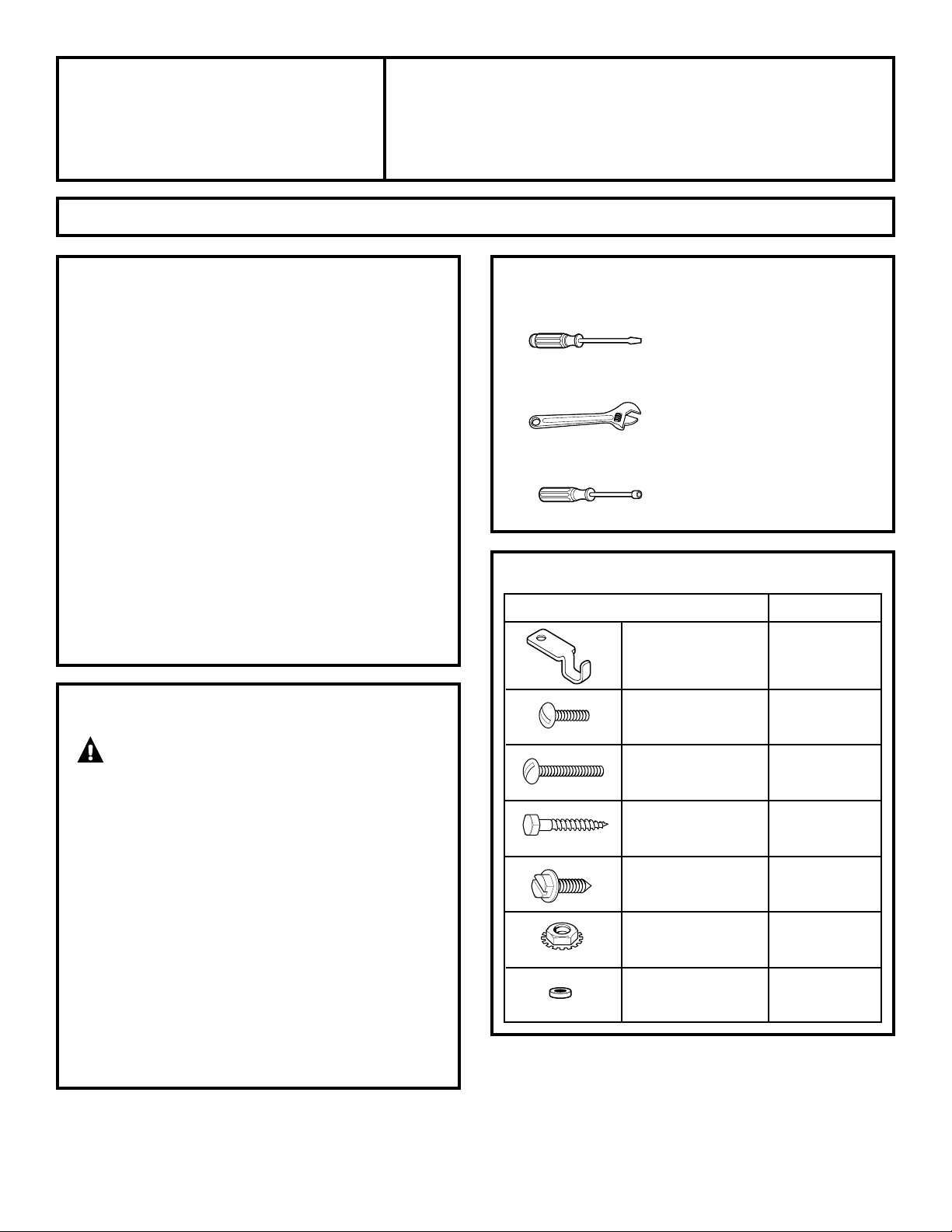
TOOLS YOU WILL NEED
• Flat-head screwdriver
• Adjustable wrench
• Nut driver
PARTS INCLUDED
PART QUANTITY
Lid Latch 1
Type A Screw 2
1/4–20 x 3/4
Type B Screw 6
1/4–20 x 1
1
⁄2
Type C Screw 2
1/4–10 x 1
3
⁄4
Type D Screw 7
10–16 x 5/8
Lock Nut 8
1/4–20
Spacer Ring 1
175D1807P423
49-90159
03-03 JR
Page 2
Installation Instructions
2
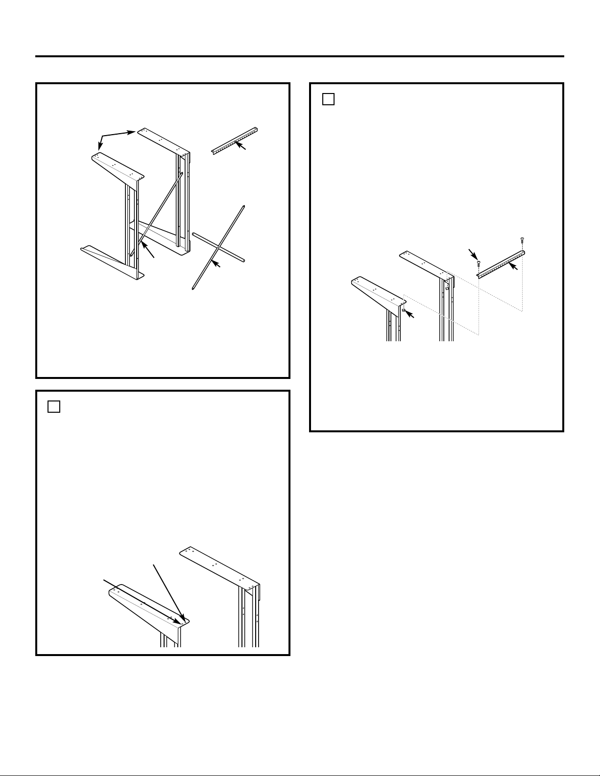
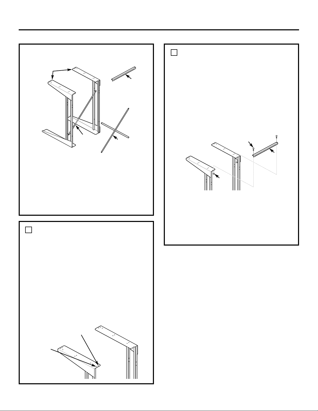
PARTS INCLUDED (cont.)
The stand base has an angle bracket at each
end. One end of the angle bracket is 22
1
⁄2″
long and has mounting holes in it. This end
goes up. The other end of the angle bracket
is 28″ long and has no holes. This longer end
(without holes) goes down.
DETERMINE STAND WIDTH
Your new stand can be assembled to two
different widths:
• 22″ for smaller, compact washers
• 24″ for larger washers
Check your washer width to determine the
stand width you need. The compact dryer
will assemble to either width.
1
ATTACH WALL MOUNTING BRACKET
Attach one end of the wall mounting
bracket to one of the upper rear holes on
one of the stand bases using a Type A
screw and a lock nut. Make sure screws are
inserted from the top and the lock nuts are
on the bottom. Use the inside hole on the
stand base for 24″ width. Use the outside
hole for 22″ width.
2
Attach the other end of the bracket to the
upper rear hole of the other stand base the
same way. Use the inside hole on the stand
base for 24″ width or the outside hole for
22″ width. Hand-tighten the screws and
nuts.
Bracket
Type A Screw
Lock
Nut
Use outside
holes for
22″ models
Use inside
holes for
24″ models
Wall
Mounting
Bracket
Cross
Brace
Diagonal
Brace
Stand Bases
Page 3
Installation Instructions
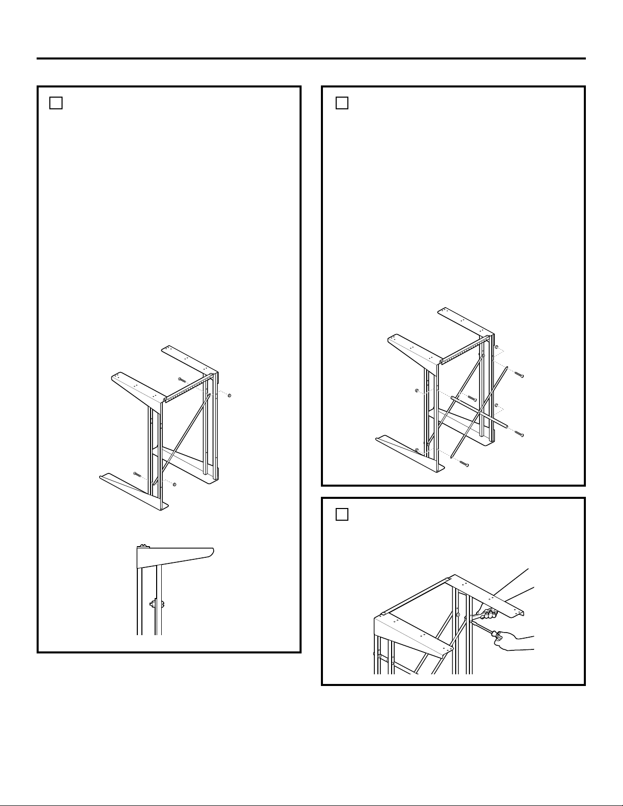
3
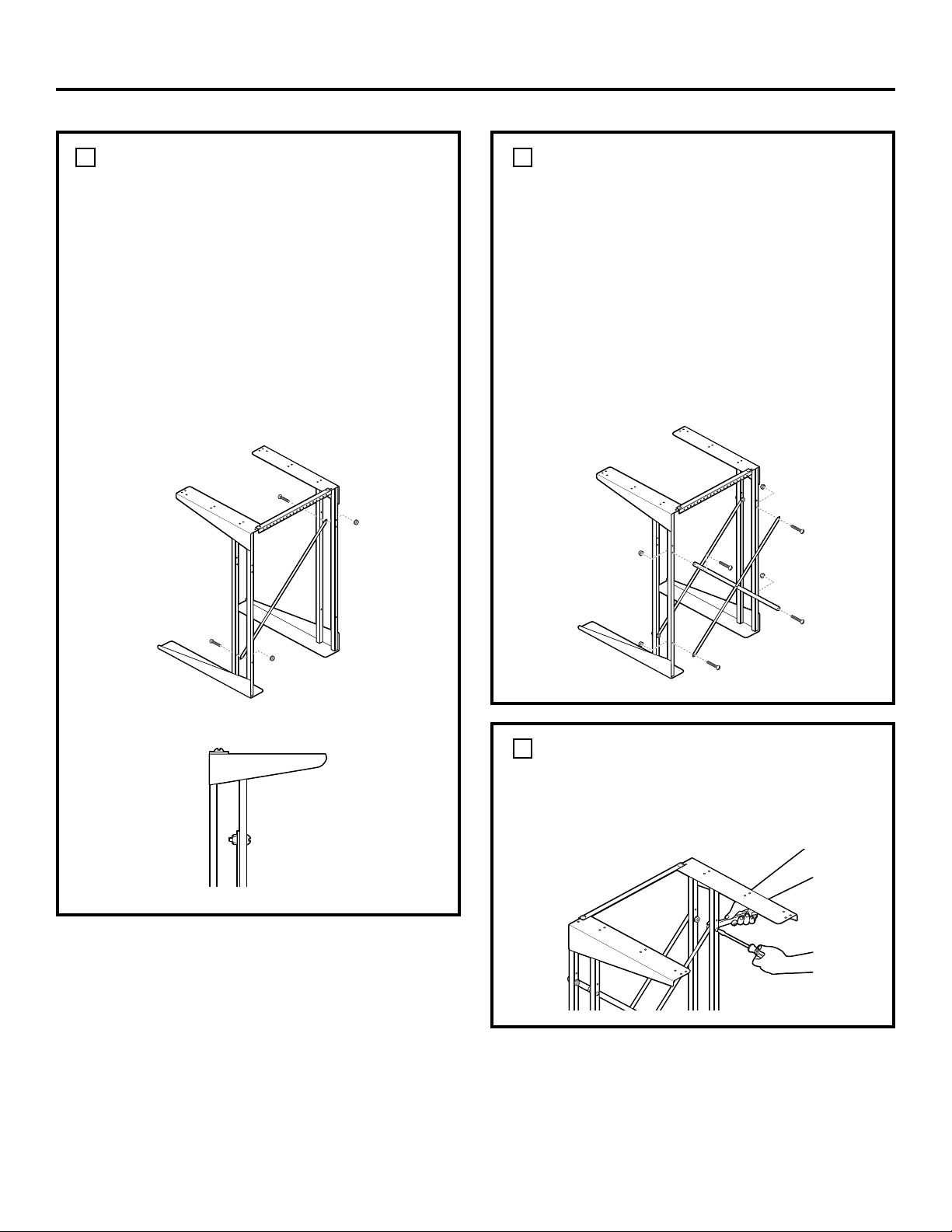
ATTACH DIAGONAL BRACE
Attach the diagonal brace to the back of the
front uprights on the stand bases. The brace
must run from the lower left to the upper
right when viewed from the rear of the stand.
Insert a Type B screw from the front of the
stand into the lower hole on the left upright
and secure with a lock nut. The lock nut will
be on the inside of the upright.
Insert another Type B screw into the hole on
the right upright. The top hole is used for 22″
width, and the lower hole is used for 24″
width. Hand-tighten the screws and lock nuts.
3
ATTACH CROSS BRACE
Attach the cross brace to the rear uprights
on the stand bases.
Insert two Type B screws from the rear
of the stand into the lower holes on the
uprights and secure with lock nuts. The lock
nuts will be on the insides of the uprights.
Insert two Type B screws into the upper
holes on the uprights. The top holes are
used for 22″ width, and the lower holes are
used for 24″ width. Hand-tighten the screws
and lock nuts.
4
TIGHTEN LOCK NUTS
Securely tighten all lock nuts using a
screwdriver and an adjustable wrench
or nut driver.
5
Page 4
Installation Instructions
4
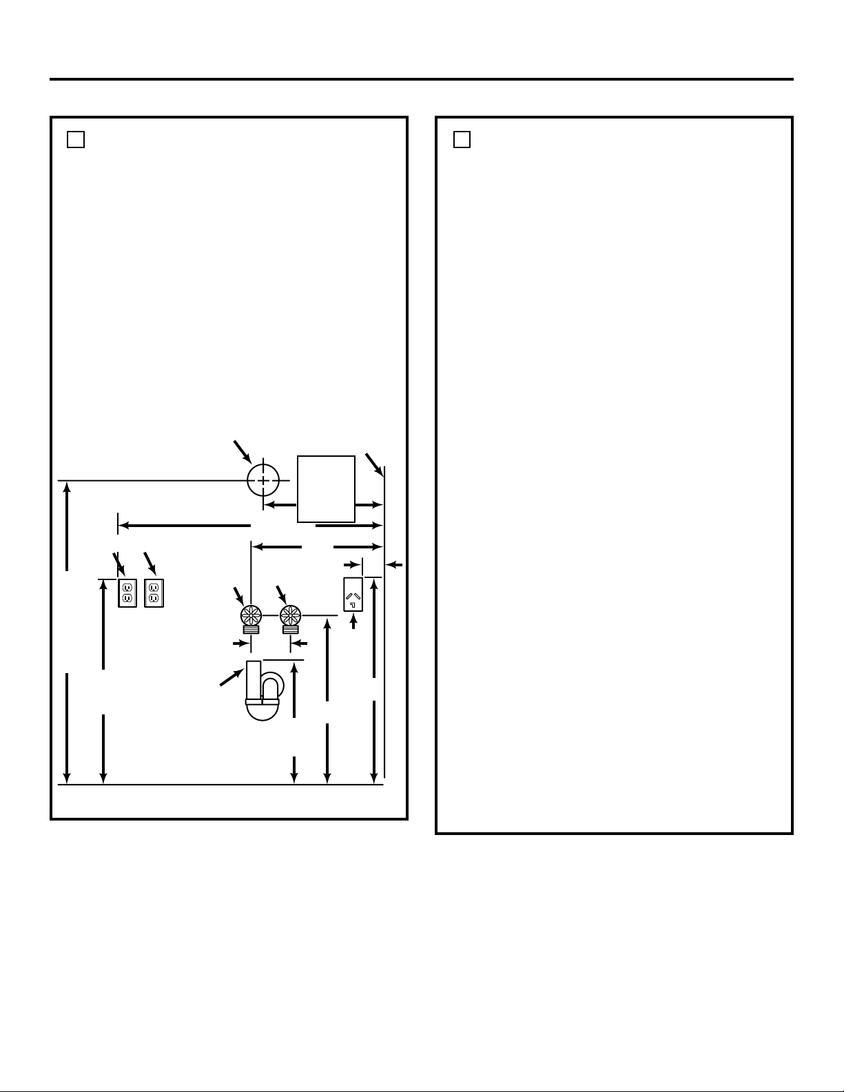
DETERMINE LOCATION
Locate the stand in an appropriate level
area. This location should be suitable for the
size, function, and protection of the stack
stand and appliances. Use the stack stand
only for the purpose for which it was
designed. To prevent restriction of airflow,
do not use top of dryer for storage.
The proper location of all utility
connections is shown in the Utilities and
Grounding illustration. These are not all
needed in each installation, but those
used should be located according to these
dimensions so that utilities can be reached
after installation.
6
DETERMINE LOCATION (cont.)
Dryers
Dryer models may require different utilities;
refer to the Installation Instructions included
with your new dryer for details on required
utilities.
Refer to the Utilities and Grounding
illustration and the Dryer Installation
Instructions for details on final utility
connections and grounding information.
NOTE: All fittings and outlets must be
located so that they clear cross members
of stack stand.
Automatic Washers
All automatic washers require a hot and
cold water supply, a proper drain and a
120-volt electrical supply. Refer to the
Installation Instructions included with
your new automatic washer for detailed
installation requirements.
If the automatic washer is to be operated
in a different location (portable) and only
stored in the stack stand, those utilities
marked with an asterisk (*) in the Utilities
and Grounding illustration would not be
required at this location. They would be
required at the location where the automatic
washer is to be operated, with the exception
of the drain pipe, since the machine can be
drained into a sink or laundry tub.
NOTE: If both the automatic washer and
dryer require a 120-volt electrical supply,
TWO separate 15-ampere circuits must be
used (one for each appliance). DO NOT,
under any circumstances, connect both
appliances to the same circuit as blown
fuses will result.
6
Utilities and Grounding
240
Vol t
Outlet
221⁄2″
15″
161⁄4″
(22″ Width)
17
1
⁄4″
(24″ Width)
Right Side of
Dryer Stand
Installed
4″ Diameter
Exhaust Location
120 Volt Outlets*
Cold Water
Faucet*
4″
381⁄4″
36″
32″
Minimum
From Floor
2″
Diameter
Pipe*
Minimum
383⁄4″
From
Floor
831⁄2″
(Top
Exhaust)
731⁄2″
(Rear
Exhaust)
From
Floor
Hot
Water
Faucet*
6″
Page 5

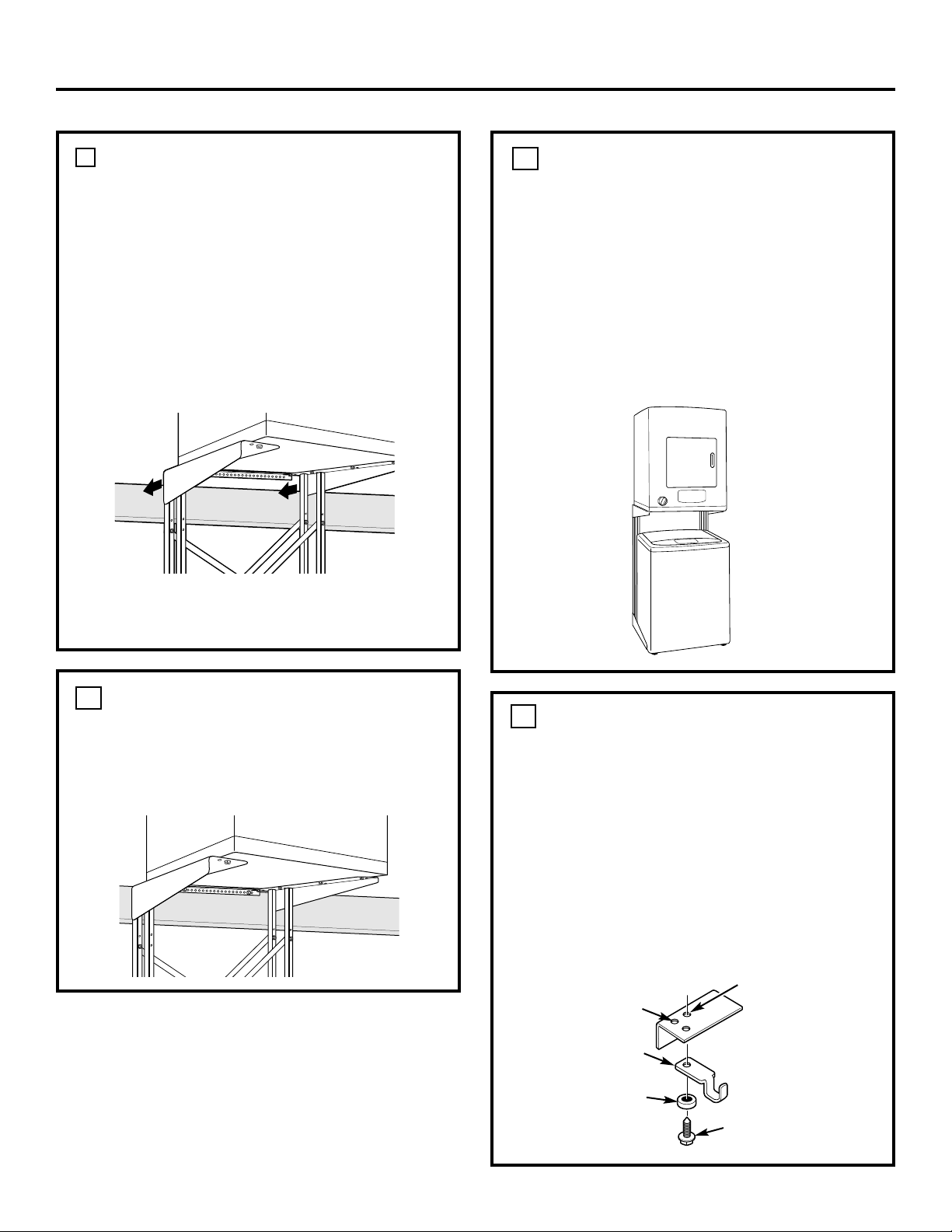
Installation Instructions
5
LOCATE MOUNTING HOLES
Push the dryer and stand against the wall
in the selected location and locate two wall
studs.
Start 2 Type C screws through holes in the
mounting bracket that line up with studs. DO
NOT SCREW IN ALL THE WAY. Multiple holes
in the bracket allow for variation in location
of wall studs.
7
INSTALL DRYER TO STAND
Carefully follow section entitled Preparing
Your Dryer for Installation in the Installation
Instructions for your new dryer. The dryer
weighs approximately 100 pounds.
WARNING
Potential Personal Injury. More than one
person is recommended to lift the dryer
into position because of its weight and size.
Failure to do so could result in personal
injury or death.
Use 6 Type D screws to secure the dryer to
the stand. Tighten the screws using an
adjustable wrench or nut driver. The dryer
will sit approximately 1
1
⁄4″ forward of the
end of the top angle.
8
NOTE: The outside holes are used for 22″
width, and the inside holes are used for 24″
width.
Once the holes are started, remove the screws
from the mounting bracket and move the
stand away from the wall.
For installations requiring clearance from
the wall:
If the stand cannot be pushed all the way
against the wall, secure a piece of wood to
the wall studs to line up with the holes on the
mounting bracket. The wood must be the
same thickness as the clearance. Follow the
steps above, starting the screws in the piece
of wood.
Page 6

Installation Instructions
MOVE DRYER AND STAND INTO FINAL POSITION AND INSTALL DRYER EXHAUST
Push the dryer and stand against the wall in
the selected location.
If the hole for the exhaust has been
located as shown in the Utilities and
Grounding illustration, it will align with the
dryer exhaust when the stack stand and
dryer are placed in the selected operating
position.
9
INSTALL WASHER
Follow the Installation Instructions
included with your washer to make washer
connections.
After washer connections are made,
move the washer into its operating position
between the stand side sections and push it
completely toward the rear. Use care not to
kink or pinch the water inlet hose, and be
sure the drain hose is placed in the drain
pipe with no kinks or twists.
Follow the Installation Instructions
included with your dryer to make exhaust
connections.
SECURE STAND TO WALL
After the exhaust is connected and the dryer
and stack stand are in the selected operating
position, secure the stand to the wall using 2
Type C screws in the holes started earlier.
10
INSTALL LID LATCH
If a washer with a lift lid is to be installed and
used under the stand, install the washer lid
latch as shown using a Type D screw in the
hole behind one of the front mounting holes.
The lid latch may be installed on either side.
NOTE: The screw for the lid latch will thread
into bottom of the dryer. Tighten securely
using a nut driver.
11
12
Dryer Mounting
Holes
Lid Latch
Mounting Hole
Lid Latch
Type D Screw
Spacer Ring
6
Page 7

AVANT DE COMMENCER
Veuillez lire les instructions complètement et
attentivement.
•
IMPORTANT
– Conservez ces instructions
pour l’inspecteur local en électricité.
•
IMPORTANT – Respectez tous les codes
et décrets pertinents.
• Note à l’installateur – N’oubliez pas de remettre
ces instructions au consommateur.
• Note au consommateur – Conservez ces
instructions pour consultation future.
• L’installation et l’entretien doivent être effectués
par un installateur qualifié.
• L’installateur assume la responsabilité d’une
bonne installation.
Instructions
Nécessaire de
d’installation
support d’empilage
Questions ? Appelez le 800.GE.CARES (800.432.2737) ou visitez notre site Web à : www.GEAppliances.com
POUR VOTRE SÉCURITÉ:
AVERTISSEMENT
• Risque de choc électrique. Débranchez l’appareil
avant de l’entretenir. Sinon, vous risquez de
vous blesser gravement ou mortellement.
• Risque de blessures corporelles. Il est
recommandé de se mettre à deux personnes
pour soulever la sécheuse afin de la mettre en
place en raison de son poids et de sa taille.
Sinon, vous risquez de vous blesser gravement
ou mortellement.
• Évitez d’incliner l’appareil et de couper l’eau
ou l’électricité. Le support doit être assemblé
avec soin et la sécheuse fixée sur son support
selon les instructions d’installation. Le support
doit être solidement fixé au mur, selon les
instructions d’installation. Sinon, vous risquez
de vous blesser gravement/mortellement ou
d’endommager des biens.
POUR EMPLOI AVEC LES SÉCHEUSES
ÉLECTRIQUES RECOMMANDÉES DE TYPE
COMPACT
LES OUTILS DONT VOUS AUREZ
BESOIN
• Tournevis à lame plate
• Clé à molette
• Monte-démonte écrou
PIÈCES INCLUSES
PIÈCE QUANTITÉ
Loquet de 1
couvercle
Vis de type A 2
de 1/4–20 x 3/4
Vis de type B 6
de1/4–20 x 1
1
⁄2
Vis de type C 2
de 1/4–10 x 1
3
⁄4
Vis de type D 7
de 10–16 x 5/8
Contre-écrou 8
1/4–20
Cale en 1
rondelle
175D1807P423
49-90159
03-03 JR
Page 8
Instructions d’installation
2
La base du support comporte une cornière
d’angle à chaque extrémité. Une extrémité
de la cornière d’angle mesure 22
1
⁄
2 po. de
longueur et est percée de trous de montage.
Cette extrémité est horizontale. L’autre
extrémité de la cornière d’angle mesure
28 po. de longueur et n’a pas de trou.
L’extrémité la plus longue (sans trou)
est verticale.
DÉTERMINEZ LA LARGEUR DU SUPPORT
Votre nouveau support peut être monté selon
deux largeurs différentes :
• 22 po. pour les petites laveuses
compactes
• 24 po. pour les grosses laveuses
Vérifiez la largeur de votre laveuse afin
de déterminer la largeur du support
nécessaire. La sécheuse compacte
se monte sur l’une ou l’autre des largeurs.
1
FIXEZ L’APPLIQUE DE
MONTAGE MURALE
Fixez une extrémité de l’applique
de montage murale sur l’un des trous
arrière supérieurs de l’une des bases du
support à l’aide d’une vis de type A et d’un
contre-écrou. Assurez-vous d’insérer les vis
par le haut et de poser les contre-écrous par
le bas. Utilisez le trou intérieur de la base
du support pour une largeur de 24 po.
Utilisez le trou extérieur pour une largeur
de 22 po.
2
Fixez l’autre extrémité de l’applique sur
le trou arrière supérieur de l’autre base
du support en procédant de la même façon.
Utilisez le trou intérieur de la base du
support pour une largeur de 24 po. ou le
trou extérieur pour une largeur de 22 po.
Serrez à la main les vis et les contre-écrous.
Applique
Vis de type A
Contreécrou
Utilisez
les trous
extérieurs
pour les
modèles
de 22 po.
Utilisez les trous
intérieurs pour les
modèles de 24 po.
PIÈCES INCLUSES (suite)
Applique de
montage
murale
Entretoise
transversale
Entretoise
diagonale
Bases du
support
Page 9
Instructions d’installation
3
FIXEZ L’ENTRETOISE
DIAGONALE
Fixez l’entretoise diagonale à l’arrière
des montants avant des bases du support.
L’entretoise doit aller du coin inférieur
gauche jusqu’au coin supérieur droit
lorsqu’on regarde le support par l’arrière.
Insérez une vis de type B par l’avant du
support dans le trou inférieur sur le montant
de gauche et fixez-la avec un contre-écrou.
Le contre-écrou doit se trouver à l’intérieur
du montant.
Insérez une autre vis de type B dans le trou
du montant de droite. Utilisez le trou du haut
pour une largeur de 22 po. ou le trou du bas
pour une largeur de 24 po. Serrez à la main
les vis et les contre-écrous.
3
FIXEZ L’ENTRETOISE
TRANSVERSALE
Fixez l’entretoise transversale aux montants
arrière des bases du support.
Insérez deux vis de type B par l’arrière
du support dans les trous inférieurs des
montants et les fixer avec les contre-écrous.
Les contre-écrous doivent se trouver à
l’intérieur des montants.
Insérez deux vis de type B dans les trous
supérieurs des montants. Utilisez les trous
du haut pour une largeur de 22 po. ou les
trous du bas pour une largeur de 24 po.
Serrez à la main les vis et les contre-écrous.
4
SERREZ LES CONTRE-ÉCROUS
Serrez à fond tous les contre-écrous à l’aide
d’un tournevis et d’une clé à molette ou
d’un monte-démonte écrou.
5
Page 10

Instructions d’installation
4
DÉTERMINEZ L’EMPLACEMENT
Placez le support sur une surface de niveau
appropriée. L’endroit doit être convenable
aux dimensions, à la fonction et à la
protection du support d’empilage et des
appareils. N’utilisez le support d’empilage
qu’aux fins pour lesquelles il a été conçu.
Afin d’éviter de bloquer le débit d’air, ne pas
utiliser le dessus de la sécheuse comme
surface de rangement.
L’illustration ci-dessous montre les
endroits appropriés pour le branchement
de l’eau, de l’électricité et de la prise de terre.
Tous ces services d’utilité publique ne sont
pas nécessaires pour chaque installation,
mais ceux utilisés devraient être situés
conformément à ces dimensions afin de
pouvoir être atteint après l’installation.
6
DÉTERMINEZ L’EMPLACEMENT
(suite)
Sécheuses
Divers modèles de sécheuses peuvent
nécessiter différents services d’utilité
publique; consultez les instructions
d’installation incluses avec votre nouvelle
sécheuse pour des détails sur les services
requis.
Consultez l’illustration des services d’utilité
publique et de mise à la terre ainsi que les
instructions d’installation de votre sécheuse
pour des détails sur les branchements
définitifs et des renseignements sur la
mise à la terre.
NOTE : Tous les raccords et les prises
doivent être placés de façon à être dégagés
de toute partie du support d’empilage.
Laveuses automatiques
Toutes les laveuses automatiques ont
besoin d’une arrivée d’eau chaude et d’eau
froide, d’un drain approprié et d’une prise
de courant de 120 volts. Consultez les
instructions d’installation incluses avec
votre nouvelle laveuse automatique pour
des détails sur les exigences de l’installation.
Si la laveuse automatique doit fonctionner
dans un endroit différent (modèle portatif)
et uniquement rangée dans le support
d’empilage, il n’y a pas besoin d’y avoir
ici les services marqués d’un astérisque (*)
dans l’illustration des services d’utilité
publique et de mise à la terre. Par contre,
ils seront nécessaires à l’endroit où la
laveuse automatique doit fonctionner, à
l’exception du tuyau de drain, étant donné
que la machine peut être vidée dans un
évier ou une cuve de lavage.
NOTE : Si la laveuse automatique et la
sécheuse exigent toutes deux un courant
de 120 volts, utilisez deux circuits distincts
de 15 ampères chacun (un pour chaque
appareil). En aucun cas, NE branchez PAS
les deux appareils sur le même circuit, car
les fusibles sauteront.
6
Services d’utilité publique et mise à la terre
Prise
de 240
volts
221⁄
2
po.
15
po.
161⁄4 po.
(22 po. de larg.)
171⁄4 po.
(24 po. de larg.)
Côté droit de
la sécheuse
installée
Sortie d’air de 4
po. de diamètre
Prises de 120 volts*
Robinet
d’eau froide*
4 po.
381⁄4
po.
36 po.
32 po. au minimum
du plancher
Tuyau* de
2 po. de
diam. au
minimum
38
3
⁄4
po. à
partir du
sol
831⁄2 po.
(Sortie
du haut)
731⁄2 po.
(Sortie
arr.)
À partir
du sol
Robinet
d’eau
chaude*
6″
Page 11

Suivez attentivement la section intitulée
Préparez votre sécheuse pour l’installation,
dans les instructions d’installation de
votre nouvelle sécheuse. La sécheuse
pèse environ 100 livres.
AVERTISSEMENT
Risque de blessures corporelles.
Il est recommandé de se mettre à deux
personnes pour soulever la sécheuse en
position en raison de son poids et de sa
taille. Sinon, vous risquez de vous blesser
sérieusement ou même mortellement.
Utilisez des vis de type D pour fixer
la sécheuse sur le support. Serrez les
vis à l’aide d’une clé à molette ou un
monte-démonte écrou. La sécheuse
reposera environ à 1
1
⁄
4 po en avant de
l’extrémité de l’angle supérieur.
Instructions d’installation
5
REPÉREZ LES TROUS
DE MONTAGE
Poussez la sécheuse et le support contre
le mur à l’endroit que vous avez choisi et
repérez deux colombages dans le mur.
Insérez deux vis de type C dans les
trous de l’applique de montage en face de
colombages. NE VISSEZ PAS À FOND. Il y a
plusieurs trous dans l’applique afin de
s’aligner facilement avec les colombages.
7
INSTALLEZ LA SÉCHEUSE SUR LE SUPPORT
8
NOTE : Utilisez les trous extérieurs pour
une largeur de 22 po. ou les trous intérieurs
pour une largeur de 24 po.
Une fois que les trous sont commencés,
enlevez les vis de l’applique de montage et
retirez le support complètement du mur.
Pour les installations qui exigent un
espace libre entre le mur :
Si le support ne peut pas être complètement
adossé au mur, glissez un morceau de bois
contre les colombages dans le mur en face
des trous de l’applique de montage. Le
morceau de bois doit avoir la même épaisseur
que l’espace libre nécessaire. Suivez les
étapes ci-dessus, en commençant à engager
les vis dans le morceau de bois.
Page 12
Instructions d’installation
6
PLACEZ LA SÉCHEUSE ET LE
SUPPORT À LEUR POSITION
DÉFINITIVE ET INSTALLEZ LA
SORTIE D’AIR DE LA SÉCHEUSE
Poussez la sécheuse et le support contre le
mur à l’endroit voulu.
Si le trou de la sortie d’air a été placé comme
il est montré dans l’illustration des services
d’utilité publique et de mise à la terre, il
s’alignera avec la sortie de la sécheuse
lorsque le support d’empilage et la sécheuse
seront placés à l’endroit choisi.
9
INSTALLEZ LA LAVEUSE
Suivez les instructions d’installation
fournies avec votre laveuse pour effectuer
les raccordements.
Une fois que les raccordements de la
laveuse sont effectués, placez la laveuse
à sa position de fonctionnement entre les
sections latérales du support et poussez-la
complètement vers l’arrière. En veillant à ne
pas plier ni coincer le boyau d’arrivée d’eau,
et assurez-vous que le tuyau de drain est
inséré dans le drain sans pli ni torsion.
Suivez les instructions d’installation
fournies avec votre sécheuse pour effectuer
les raccordements de sortie d’air.
FIXEZ LE SUPPORT AU MUR
Une fois que la sortie d’air est branchée et
que la sécheuse et le support se trouvent à
l’endroit choisi, fixez le support au mur à
l’aide de deux vis de type C dans les trous
qui ont été commencés auparavant.
10
INSTALLEZ LE LOQUET DU COUVERCLE
Si une laveuse avec un couvercle soulevable doit
être installé et utilisé sous le support, installez le
loquet du couvercle comme illustré à l’aide d’une
vis de type D dans le trou derrière l’un des trous
de montage avant.
Le loquet du couvercle peut s’installer d’un côté
ou de l’autre.
REMARQUE : La vis du loquet du couvercle se fixe
dans le bas de la sécheuse. La serrer à fond avec
un monte-démonte écrou.
11
12
Trous de montage
de la sécheuse
Trou de montage du
loquet de couvercle
Loquet du
couvercle
Vis de type D
Cale en rondelle
 Loading...