

Page 1

g
t
GE Power Managemen
SPM
SYNCHRONOUS MOTOR PROTECTION
AND CONTROL
Instruction Manual
Software Revision: 210.000
Manual P/N: 1601-0072-A6
Copyright © 2001 GE Power Management
GE Power Management
215 Anderson Avenue, Markham, Ontario
Canada L6E 1B3
Tel: (905) 294-6222 Fax: (905) 294-8512
Internet: http://www.GEindustrial.com/pm
Manufactured under an
ISO9001 Registered system.
Page 2

Page 3

These instructions do not purpor t to cover all detai ls or varia tions in equipment nor provide fo r every p ossibl
e
e
e
t
contingency to be met in connection with installation, operation, or maintenance. Should further information b
desired or should pa rticula r pro blems arise whi ch are no t cove red su ffici ently for the p urchas er’s purpose, th
matter should be referred to the General Electric Company.
To the extent required the products des cribed herein meet applic able ANSI, IEE E, and NEMA s tandards; bu
no such assurance is given with respect to local codes and ordinances because they vary greatly.
Page 4

Page 5

TABLE OF CONTENTS
1. INTRODUCTION
2. INSTALLATION
1.1 OVERVIEW
1.1.1 GENERAL DESCRIPTION........................................................................1-1
1.1.2 FUNCTIONAL OVERVIEW........................................................................1-1
1.2 ORDERING
1.2.1 ORDER CODES........................................................................................1-3
1.2.2 ACCESSORIES.........................................................................................1-3
1.3 SPECIFICATIONS
1.3.1 SPM SPECIFICATIONS............................................................................ 1-4
2.1 OVERVIEW
2.1.1 DESCRIPTION..........................................................................................2-1
2.1.2 ELEMENTS OF A SYNCHRONOUS MOTOR CONTROLLER................. 2-1
2.2 MECHANICAL INSTALLATION
2.2.1 UNPACKING THE SPM.............................................................................2-2
2.2.2 REMOVING THE DRAWOUT RELAY....................................................... 2-2
2.2.3 INSERTING THE DRAWOUT RELAY....................................................... 2-2
2.2.4 MOUNTING THE SPM.............................................................................. 2-2
2.2.5 SPM MOUNTING ACCESSORIES............................................................2-2
2.3 ELECTRICAL INSTALLATION
2.3.1 DESCRIPTION..........................................................................................2-4
2.3.2 GROUNDING.............................................................................................2-6
2.3.3 FIELD AND EXCITER VOLTAGE INPUTS ...............................................2-6
2.3.4 RELAY OUTPUTS ..................................................................................... 2-6
2.3.5 CURRENT TRANSFORMER INPUT.................................... .....................2-6
2.3.6 POWER FACTOR OUTPUT......................................................................2-6
2.3.7 DC FIELD CURRENT INPUT....................................................................2-6
2.3.8 EXCITER VOLTAGE OUTPUT MONITOR................................................ 2-6
2.3.9 POWER FACTOR REGULATION OUTPUT ............................................. 2-7
2.3.10 CONTROL VOLTAGE.............. ..................... ..................... ....................... 2-7
2.3.11 EXTERNAL VOLTAGE PF REFERENCE............... ..................................2-7
2.3.12 RS485 COMMUNICATIONS PORT ..........................................................2-8
3. SYNCHRONOUS MOTOR
APPLICATIONS
3.1 OVERVIEW
3.1.1 GENERAL..................................................................................................3-1
3.2 COLLECTOR-RING MOTORS
3.2.1 STARTING AND SYNCHRONIZING......................................................... 3-5
3.2.2 RELUCTANCE TORQUE SYNCHRONIZING........................................... 3-6
3.2.3 STARTING PROTECTION...................................... ..................... .............3-7
3.2.4 REDUCED VOLTAGE STARTING............................................................3-8
3.2.5 POWER FACTOR (PULL-OUT) PROTECTION...................................... 3-10
3.2.6 POWER FACTOR OPERATION.............................................................3-11
3.2.7 CONTROLLER ACTION DURING PULL-OUT........................................3-12
a RESYNC MODE......................................... ..................... ........................3-12
b RIDE-THRU MODE .................................................................................3-12
3.2.8 EFFECT OF VOLTAGE DIPS ON MOTOR POWER FACTOR .............. 3-13
3.2.9 POWER FACTOR DETECTION & INDICATION – OVERHAULING LOAD 3-
15
3.2.10 POWER FACTOR REGULATION........................................................... 3-16
3.3 BRUSHLESS CONTROLLER
3.3.1 DESCRIPTION........................................................................................3-17
GE Power Management SPM Synchronous Motor Protection & Control
i
Page 6

TABLE OF CONTENTS
3.3.2 BRUSHLESS MOTOR REVIEW..............................................................3-17
3.3.3 STARTING THE BRUSHLESS MOTOR............... ..................... .............3-18
3.3.4 STALL PROTECTION ............................................................................. 3-19
3.3.5 POWER FACTOR (PULL-OUT) PROTECTION...................................... 3-19
3.3.6 POWER FACTOR REGULATION...........................................................3-19
4. USER INTERFACE
5. SETPOINTS
4.1 SPMPC SOFTWARE
4.1.1 DESCRIPTION ..........................................................................................4-1
4.1.2 SPMPC INSTALLATION........ .................................................................... 4-2
4.1.3 CONFIGURATION.................................................................................. ... 4-3
4.1.4 CREATING A NEW SETPOINT FILE ........................................................ 4-4
4.1.5 EDITING A SETPOINT FILE .....................................................................4-5
4.1.6 LOADING SETPOINTS FROM A FILE.................. ..................... ...............4-6
4.1.7 UPGRADING SETPOINT FILES TO A NEW REVISION.......................... 4-7
4.1.8 PRINTING SETPOINTS & ACTUAL VALUES........................................... 4-8
4.1.9 TRENDING................................................................................................ 4-9
4.2 KEYPAD INTERFACE
4.2.1 DESCRIPTION ........................................................................................4-10
4.2.2 CHANGING SETPOINTS ........................................................................ 4-11
4.2.3 CHANGING CALIBRATION VALUES............ .........................................4-12
4.2.4 CHANGING CONFIGURATIONS............................................................4-13
4.2.5 VIEWING & CHANGING STATUS MODE PARAMETERS.....................4-14
4.2.6 ALTERNATE MENU OPERATION ..........................................................4-14
5.1 OVERVIEW
5.1.1 DESCRIPTION ..........................................................................................5-1
5.2 SETPOINTS MENU
5.2.1 POWER FACTOR TRIP............................................................................ 5-2
5.2.2 POWER FACTOR DELAY......................................................................... 5-2
5.2.3 POWER FACTOR SUPRESSION.............................................................5-2
5.2.4 POWER FACTOR MODE..........................................................................5-3
5.2.5 FIELD APPLICATION RELAY DELAY ............... .......................................5-3
5.2.6 FIELD CONTACTOR AUXILIARY RELAY DELAY.................................... 5-3
5.2.7 AC CT PRIMARY RATING........................................................................5-4
5.2.8 MOTOR FULL LOAD AMPS......................................................................5-4
5.2.9 MOTOR LOCKED ROTOR AMPS.............................................................5-4
5.2.10 SYNCHRONOUS SLIP.............. ................................................................5-5
5.2.11 STALL TIME .................. ..................... .......................................................5-5
5.2.12 RUN TIME..................................................................................................5-5
5.2.13 DIRECT CURRENT CT PRIMARY RATING .............................................5-6
5.2.14 FIELD OVERTEMPERATURE (HIGH FIELD OHMS) PROTECTION.......5-7
5.2.15 FIELD UNDERCURRENT ....................................... .................................. 5-8
5.2.16 FIELD UNDERCURRENT DELAY................................................ .............5-8
5.2.17 FIELD UNDERVOLTAGE .......................................................................... 5-8
5.2.18 FIELD UNDERVOLTAGE DELAY................ ........................................ ..... 5-9
5.2.19 INCOMPLETE SEQUENCE DELAY..........................................................5-9
5.3 OPTIONAL POWER FACTOR REGULATION SETPOINTS
5.3.1 DESCRIPTION ........................................................................................5-10
5.3.2 POWER FACTOR REGULATOR............................................................5-10
5.3.3 REGULATOR GAIN................................................................................. 5-10
5.3.4 STABILITY............................................................................................... 5-10
5.3.5 REGULATOR OUTPUT LIMIT.................................................................5-11
ii
SPM Synchronous Motor Protection & Control
GE Power Management
Page 7

TABLE OF CONTENTS
5.3.6 FLOOR VOLTS........................................................................................ 5-11
5.4 CONFIGURATIONS MENU
5.4.1 MOTOR TYPE.......................................... ............................................... 5-12
5.4.2 LINE FREQUENCY .................................... .............................................5-12
5.4.3 POWER FACTOR REFERENCE............................................................ 5-12
5.4.4 RTU ADDRESS.................................... ............................................ ....... 5-12
5.4.5 BAUD RATE ................ ..................... ..................... ..................... ............. 5-12
5.4.6 PARITY........... ..................... .................................................................... 5-12
5.4.7 TURNAROUND ........................ ...............................................................5-13
5.4.8 STATUS MODE....................................................... ..................... ........... 5-13
5.4.9 PASSWORD......................................................................................... ...5-13
5.5 CALIBRATION MENU
5.5.1 FULL-SCALE EXCITER DC VOLTAGE ..................................................5-14
5.5.2 FULL-SCALE EXCITER DC AMPS .........................................................5-14
5.5.3 FULL-SCALE MOTOR AC AMPS............................................................5-14
6. ACTUAL VALUES
7. TESTING AND
TROUBLESHOOTING
6.1 DISPLAY SCROLLING
6.1.1 DESCRIPTION..........................................................................................6-1
6.2 STATUS
6.2.1 MOTOR RUNNING HOURS...................................................................... 6-2
6.2.2 INCOMPLETE SEQUENCE TRIP COUNTER .......................................... 6-2
6.2.3 FIELD LOSS TRIP COUNTER .................................................................. 6-2
6.2.4 PULL-OUT TRIP COUNTER..................................................................... 6-2
6.2.5 RESYNCRONIZATION ATTEMPTS TRIP COUNTER.............................. 6-2
6.2.6 MISSING EXTERNAL PF VOLTAGE REFERENCE COUNTER.............. 6-2
6.2.7 CHECK EXCITER TRIP COUNTER.......................................................... 6-3
6.2.8 POWER FACTOR TRIP COUNTER.......................................................... 6-3
6.2.9 SQUIRREL CAGE TRIP COUNTER......................................................... 6-3
6.2.10 FIELD OVERVOLTAGE TRIP COUNTER................................................. 6-3
7.1 START-UP PROCEDURE
7.1.1 INSPECTION.............................................................................................7-1
7.1.2 SPM TEST CHECKS...... ............. .............. .. ............. ............. .. .............. .... 7- 1
a STANDBY MODE ...................................................................................... 7-1
b TEST MODE..............................................................................................7-1
7.1.3 START-UP DESCRIPTION....................................................................... 7-2
7.2 DISPLAY AND MESSAGES
7.2.1 DISPLAY.................................................................................................... 7-3
7.2.2 SPM MESSAGES...................................................................................... 7-3
7.3 REGULATOR TUNE-UP
7.3.1 INSTRUCTIONS........................................................................................ 7-5
7.4 TROUBLESHOOTING
7.4.1 TROUBLESHOOTING GUIDE....................................................... ........... 7-6
7.5 PROGRAMMING
7.5.1 PROGRAMMING EXAMPLE..................................................................... 7-8
7.6 DOs AND DON’Ts
7.6.1 DOs.......................................................................................................... 7-12
7.6.2 DON'Ts.................................................................................................... 7-12
GE Power Management SPM Synchronous Motor Protection & Control
iii
Page 8

TABLE OF CONTENTS
7.7 FREQUENTLY ASKED QUESTIONS
7.7.1 SPM FAQ.................................................................................................7-13
7.8 REVISION HISTORY
7.8.1 FIRMWARE .............................................................................................7-15
7.8.2 SUMMARY...............................................................................................7-16
8. ACCESSORIES
9. MODBUS
COMMUNICATIONS
10. FUNCTIONAL TESTS
8.1 VOLTAGE DIVIDER NETWORK
8.1.1 GE POWER MANAGEMENT VDN............................................................ 8-1
8.1.2 GE MEBANE VDN.....................................................................................8-2
8.2 FIELD CURRENT CALIBRATION MODULE
8.2.1 GE POWER MANAGEMENT MODULE....................................................8-3
8.3 DC CURRENT TRANSFORMER
8.3.1 DESCRIPTION ..........................................................................................8-5
9.1 IMPLEMENTATION
9.1.1 MODBUS PROTOCOL.............................................................................. 9-1
9.1.2 PERFORMANCE REQUIREMENTS......................................................... 9-1
9.1.3 SETPOINTS............................................................................................... 9-1
9.1.4 EXECUTE OPERATION COMMAND CODES (COIL NUMBERS) ...........9-1
9.2 MEMORY MAPPING
9.2.1 MODBUS MEMORY MAP ......................................................................... 9-2
9.2.2 FORMAT CODES......................................................................................9-7
10.1 INTRODUCTION
10.1.1 DESCRIPTION ........................................................................................10-1
10.2 COLLECTOR-RING MOTOR FIELD APPLICATION TEST
10.2.1 SETUP..................................................................................................... 10-2
10.2.2 RELAY PROGRAMMING........................................................................10-2
a CONFIGURATIONS ................................................................................ 10-2
b SETPOINTS............................................................................................. 10-2
10.2.3 TEST ........................................................................................................ 10-2
10.3 COLLECTOR-RING MOTOR POWER FACTOR TEST
10.3.1 SETUP..................................................................................................... 10-3
10.3.2 RELAY PROGRAMMING........................................................................10-3
a CONFIGURATIONS ................................................................................ 10-3
b SETPOINTS............................................................................................. 10-3
10.3.3 TEST ........................................................................................................ 10-3
10.4 COLLECTOR-RING MOTOR POWER FACTOR TRIP TEST
10.4.1 SETUP..................................................................................................... 10-4
10.4.2 RELAY PROGRAMMING........................................................................10-4
a CONFIGURATIONS ................................................................................ 10-4
b SETPOINTS............................................................................................. 10-4
10.4.3 TEST ........................................................................................................ 10-4
10.5 BRUSHLESS MOTOR FIELD APPLICATION TEST
10.5.1 SETUP..................................................................................................... 10-5
10.5.2 RELAY PROGRAMMING........................................................................10-5
a CONFIGURATIONS ................................................................................ 10-5
b SETPOINTS............................................................................................. 10-5
iv
SPM Synchronous Motor Protection & Control
GE Power Management
Page 9

TABLE OF CONTENTS
10.5.3 TEST........................................................................................................ 10-5
10.6 BRUSHLESS MOTOR POWER FACTOR TEST
10.6.1 SETUP..................................................................................................... 10-6
10.6.2 RELAY PROGRAMMING........................................................................10-6
a CONFIGURATIONS ................................................................................ 10-6
b SETPOINTS............................................................................................. 10-6
10.6.3 TEST........................................................................................................ 10-6
10.7 BRUSHLESS MOTOR POWER FACTOR TRIP TEST
10.7.1 SETUP..................................................................................................... 10-7
10.7.2 RELAY PROGRAMMING........................................................................10-7
a CONFIGURATIONS ................................................................................ 10-7
b SETPOINTS............................................................................................. 10-7
10.7.3 TEST........................................................................................................ 10-7
10.8 AC CURRENT METERING AND PULL-OUT TEST
10.8.1 SETUP..................................................................................................... 10-8
10.8.2 RELAY PROGRAMMING........................................................................10-8
a CONFIGURATIONS ................................................................................ 10-8
b SETPOINTS............................................................................................. 10-8
10.8.3 TEST........................................................................................................ 10-8
10.9 EXCITER / FIELD VOLTAGE METERING TEST
10.9.1 SETUP..................................................................................................... 10-9
10.9.2 RELAY PROGRAMMING........................................................................10-9
a CONFIGURATIONS ................................................................................ 10-9
b SETPOINTS............................................................................................. 10-9
10.9.3 TEST........................................................................................................ 10-9
10.10 EXCITER / FIELD CURRENT METERING TEST
10.10.1 SETUP................................................................................................... 10-10
10.10.2 RELAY PROGRAMMING...................................................................... 10-10
a CONFIGURATIONS .............................................................................. 10-10
b SETPOINTS........................................................................................... 10-10
10.10.3 TEST...................................................................................................... 10-10
A. COMMISSIONING
B. FIGURES AND TABLES
C. WARRANTY
A.1 COMMISSIONING
A.1.1 COLLECTOR-RING SETTINGS..................................................... ...........A-1
A.1.2 BRUSHLESS SETTINGS..........................................................................A-2
B.1 FIGURES AND TABLES
B.1.1 LIST OF FIGURES................................. ..................... ..............................B-1
B.1.2 LIST OF TABLES.......................................................................................B-2
C.1 WARRANTY
C.1.1 WARRANTY..............................................................................................C-1
GE Power Management SPM Synchronous Motor Protection & Control
v
Page 10

TABLE OF CONTENTS
vi
SPM Synchronous Motor Protection & Control
GE Power Management
Page 11

1 INTRODUCTION 1.1 OVERVIEW
1 INTRODUCTION 1.1 OVERVIEW 1.1.1 GENERAL DESCRIPTION
The SPM controls starting, synchronizing, and protection of collector-ring and brushless type synchronous
motors.
The SPM control funct ion s for s tar tin g sy nc hronous motors include ac cu ra te se ns in g of mot or spe ed an d ro tor
angle, allowing the unit to apply excitation at optimum speed and angle. This per mits closer matching of the
motor to the load. Optim um application of excitation al so reduces power system dist urbance, which occurs
when the motor goes through a comple te slip cycle with the field energized. In addition, the SPM can take
advantage of the extended stall time of a r educe d volta ge star t. It also res ponds with the proper applica tio n of
excitation in the event that the motor synchronizes on reluctance torque.
The SPM provides the functions necessary to protect the motor durin g startup and in the event of async hronous operation. D uring startup and r estarting, the S PM prevents over heating of the c age winding. To protect
against asynchronous operation, the motor power factor is monitored. Two modes of pull-out protection can trip
the motor if resynchroniz ation does no t occur a fter a programm ed time del ay. Motor run time and the number
and type of trips are recorded.
The SPM has an optional power factor regulator containing five adjustable setpoints that can be changed while
the motor is running for convenient regulator tune-up.
A backlit LCD dis play and keys allow user conf igurable setting ranges to meet many applications. The unit
comes in a compact S1 drawout case.
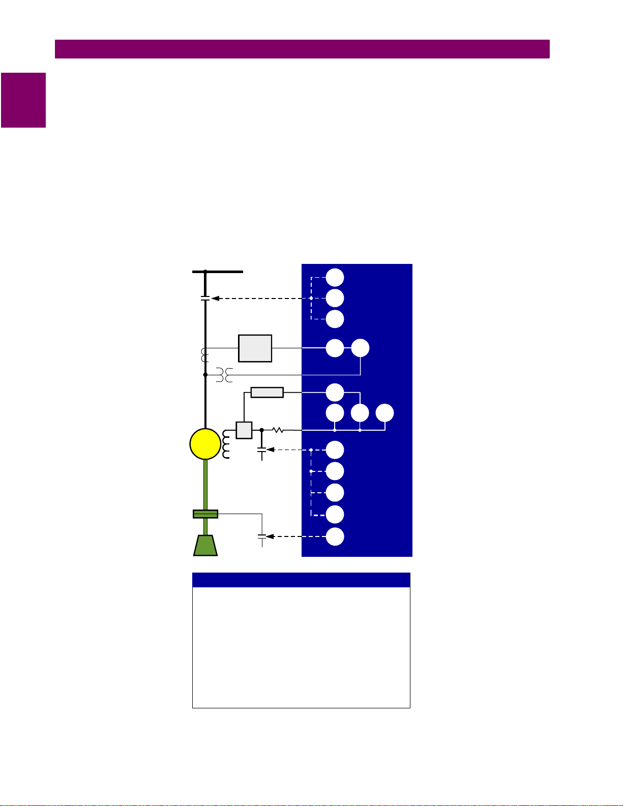
The SPM can be ap plied as part of a co mplete synchronous motor co ntroller. This consists of four parts. A
main device switche s the motor on and off the power system. Multifunction digital relays (such as the GE
Power Management 46 9 Motor Manageme nt Relay) provide stator protec tion. DC field p rotection and c ontrol
are provided by the SPM. The field contactor and field discharge resistor completes the control assembly.
1
1.1.2 FUNCTIONAL OVERVIEW
The DC portion of the s ync hronous motor (rotor assembl y) is prote cted and c ontro lled u sing a d rawout micr oprocessor based mul tifunction re lay. The relay is adaptable to either col lector-ring or b rushless ty pe synchronous motors. Protection features inc l ude all of the followi ng :
• Cage winding and stall protection during start
• Lockout feature to protect a hot rotor after an incomplete start
• Incomplete sequence trip due to failed acceleration
• Automatic acceleration time adjustment for reduced voltage starting
• Power factor (pull-out) trip with auto resynchronizing feature
• Loss of DC field current trip
• Loss of DC field voltage trip
• Field winding overtemperature trip
After a successful sta rt, the relay automatically applies the DC field to the rotor at a prescribed slip an d slip
angle to minimize mec hanical stresses to the shaft as well as minimiz es possible electrical t ransients to the
power system. This is achieved by a dedicated output to close the DC field contactor. The relay is also capable
of reluctance torque synchronizing (collector-ring machines only).
A dedicated output is prov ide d in the relay to enab le th e loa din g of the motor followi ng the DC fiel d app li ca tio n
and unloading of the motor following a trip and/or loss of synchronization (pole slipping).
Control of an SCR type exc itation syste m by me ans of a n analog output to maintain po wer fact or (PF re gulation) is available as an option.
GE Power Management SPM Synchronous Motor Protection & Control 1-
1
Page 12
1.1 OVERVIEW 1 INTRODUCTION
The man-machine in terface (MMI) cons ists of a backlit alpha numeric displa y and a keypad to ac commodate
relay programming as well as viewing actual motor parameters which comprise:
1
• AC stator current
• Power fa ctor
• DC field current
• DC field voltage
• DC field resistance
• Running time meter (RTM)
Statistical data includes number and type of trips.
The SPM performs a complete system check prior to starting the motor.
AC BUS
48
SPM
86
94
MOTOR
LOAD
CLUTCH
COUPLING
Stator
Protection
(469)
Calibrator
DC
CT
DC SUPPLY
I
AC
V
AC
I
DC
V
DC
ANSI DEVICE NUMBERS
Field overtemperature
26F
Undervoltage
27
Undercurrent or underpower
37
Incomplete sequence
48
Instantaneous overcurrent
50
Power factor
55
Field application
56
Lock out
86
Tripping
94
Reluctance torque sync. / resync.
95
Autoloading relay
96
55
50
37
27 26F 95
48
94
95
56
96
701767A9.CDR
1-
Figure 1–1: SINGLE LINE DIAGRAM
2
SPM Synchronous Motor Protection & Control GE Power Management
Page 13

1 INTRODUCTION 1.2 ORDERING
1.2 ORDERING 1.2.1 ORDER CODES
The SPM has all features built into the standard relay and programmable by the user to fit the specific application. The only option in the order code is for Power Facto r Regulation. Som e of the standard featu res require
an optional external hard ware package that must be ordered in addition to the relay it self. These separate
packages are explained in the foll owi ng se cti on.
Base Unit
Configuration
SPM
SPM |
Standard starting and protection relay with VDN board
Power Factor regulation option. Used on motors with SCR exciter
PF
(not recommended for brushless applications)
1.2.2 ACCESSORIES
PG2SPM
: External hardware package for overtemperature and current loss protection up to 200 A
(includes 1-DCCT200 & 1-CM)
PG4SPM
: External hardware package for overtemperature and current loss protection up to 400 A
(includes 1-DCCT400 or DCCT500 and 1-CM)
MPSPM
: Mounting panel to retrofit existing µSPM cutouts for SPM
1
GE Power Management SPM Synchronous Motor Protection & Control 1-
3
Page 14

1.3 SPECIFICATIONS 1 INTRODUCTION
1.3 SPECIFICATIONS 1.3.1 SPM SPECIFICATIONS
1
PHASE CURRENT INPUTS
CT Primary: 5 to 2000 A
CT Secondary: 5 A
Conversion Range: 0.05 to 6 × CT
Frequency: 50 / 60 Hz
Accuracy: at < 2 × CT: ±0.5% of 2 × CT true RMS
≥ 2 ×
at
CT: ±1% of 6 × CT true RMS
FIELD CURRENT INPUTS
CT Primary: 5 to 1000 A
Conversion Range: 0.05 to 1 × CT
Accuracy: ±2%
EXCITER VOLTAGE INPUTS
Conversion: 0 to 350 V DC (prior to VDN)
Accuracy: ±1%
POWER FACTOR
Range: 0.01 to 1 to –0.01
Time Delay: 0.1 to 10 seconds
Accuracy: ±5%
SWITCH INPUTS (MX & NX)
Type : Dr y c ont a c t
Internal Interrogation Voltage: 85 to 265 V AC (control voltage)
PF ANALOG OUTPUT
Ty pe : Ac ti ve
Output: 0 to 10 V DC max. at R
Accuracy: ±10% (0.1 V)
Isolation: 36 V pk
≥ 1 KΩ (min. load)
L
CONTROL VOLTAGE
Input: 85 to 265 V AC at 48 to 60 Hz
Power: 10 VA nominal
Holdup: 100 ms typical at 120 V AC
RELAY CONTACT
Type : FA R , T RP Form A
FCX Form C
Rated Load: 10 A AC continuous NEMA A300
1 A DC continuous NEMA R300
Break: 10 A at 250 V AC or 30 V DC
Max. Operating Voltage: 250 V AC
ENVIRONMENT
Humidity: 0 to 95% non-condensing
Operating Temp.: –20°C to +70°C
Storage Temp.: –40°C to +85°C
TYPE TESTS
Dielectric Strength: Per IEC 255-5 and ANSI/IEEE C37.90
2.0 kV for 1 min. from relays, CTs, VTs
power supply to Safety Ground
Insulation
Resistance: IEC255-5 500 VDC, from relays, CTs, VTs
power supply to Safety Ground
Transients: ANSI C37.90.1 Oscillography (2.5kV/1MHz)
ANSI C37.90.1 Fast Rise (5kV/10ns)
Ontario Hydro A-28M-82
IEC255-4 Impulse/High Frequency Disturbance,
Class III Level
Impulse Test: IEC 255-5 0.5J 5kV
EMI: C37.90.2 Electromagnetic Interference at
150 MHz and 450 MHz, 10V/m
Static: IEC801-2 Static Discharge
Vibration: Sinusoidal Vibration 8.0g for 72 hrs.
CERTIFICATION
UL: UL listed
CSA: CSA approved
PHYSICAL
Shipping Box: 12.50" × 10.50" × 9.75" (L × H × D)
318 mm × 267 mm × 248 mm (L × H × D)
Ship Weight: 14.25 lb. / 6.45 kg
1-
Specifications subject to change without notice
4
SPM Synchronous Motor Protection & Control GE Power Management
Page 15
2 INSTALLATION 2.1 OVERVIEW
2 INSTALLATION 2.1 OVERVIEW 2.1.1 DESCRIPTION
The SPM can be incorporate d in synch ronous mot or control equ ipment as a co mplete cont roller (incl uding an
AC power-switching devi ce for the motor starter) or as a field pane l (AC power switching supplied by ot her
device).
2.1.2 ELEMENTS OF A SYNCHRONOUS MOTOR CONTROLLER
A complete synchronou s-m otor contr oller has the ability to s witch the motor on to and off of the power system
and protect the motor from damage that can occur if the motor is running in an abnormal condition such as outof-synchronization.
A complete synchronou s-motor cont roller consist s of a motor starter and swi tching devic e (typically a contactor) which controls the ma in power to the motor. In addition, protectiv e relaying is pro vided for both the sta tor
and the rotor (such as a 469 /SPM com binati on). Con trols for starti ng and st opping the motor (start-s top pushbuttons) are also included. Indicating and metering de vic es such as li ne am met e rs are s upp li ed if no t in cl ude d
in the relays. All of these features are common with motor controllers of all types.
2
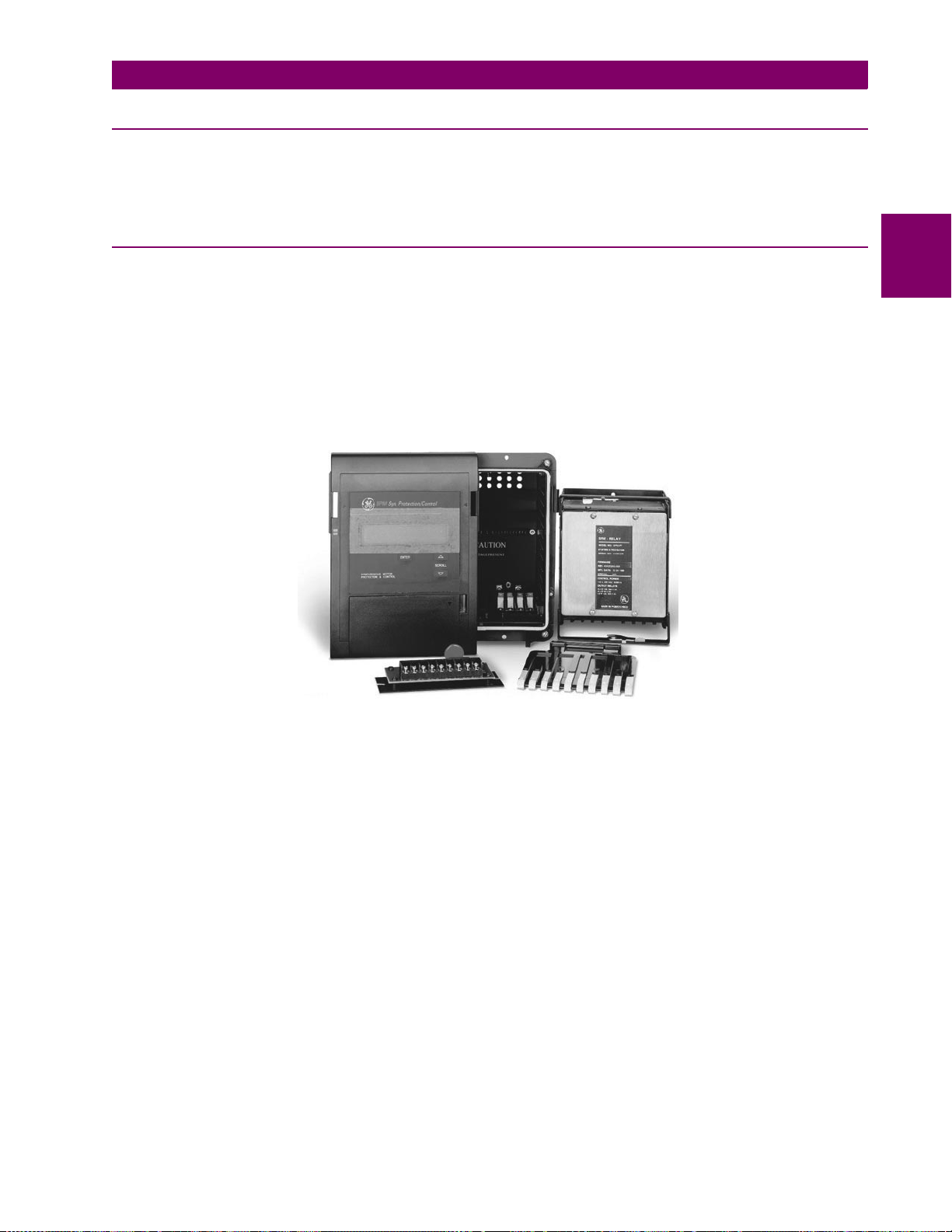
Figure 2–1: EXPLODED VIEW OF THE SPM
GE Power Management SPM Synchronous Motor Protection & Control 2-
1
Page 16

2.2 MECHANICAL INSTALLATION 2 INSTALLATION
2.2 MECHANICAL INSTALLATION 2.2.1 UNPACKING THE SPM
When the SPM is shipped separately, carefully unpack the module and report any observable damage or missing components to the c arrier and to GE Power Management. All inc luded parts are shown in Figure 2–1:
EXPLODED VIEW OF THE SPM on page 2–1.
2.2.2 REMOVING THE DRAWOUT RELAY
2
1. Remove the faceplate as sembl y care fully by pus hing i n on t he qui ck rel ease tab s on t he fro nt of th e SP M
and pulling the faceplate assembly forward. Once the faceplate has pivoted forward, gently lower the faceplate so that it clears the tabs on the bottom of the frame.
DO NOT let the faceplate assembly dangle from the connecting wires.
NOTE
2. Carefully disconnect the ribbon cable from the cradle assembly.
3. Remove the paddle and open the top and bottom lock ing tabs. The relay can n ow be removed from th e
case.
2.2.3 INSERTING THE DRAWOUT RELAY
1. Slide the relay into the case and close the top and bottom locking tabs.
2. Insert the paddle into the opening at the bottom of the relay.
3. Carefully re-connect the ribbon cable to the cradle assembly.
DO NOT shift or skew the ribbon connector.
NOTE
4. Re-mount the faceplate assembly to the case from the front panel. Slide the faceplate onto the tabs on the
bottom of the frame a nd then pivot it up into pos ition over the quick release tabs. The faceplate shoul d
gently snap into place.
2.2.4 MOUNTING THE SPM
Mounting the SPM requires careful attention to the following instructions.
DE-ENERGIZE ALL EXISTING EQUIPMENT BEFORE INSTALLING NEW EQUIPMENT.
CAUTION
1. Remove the relay from the case.
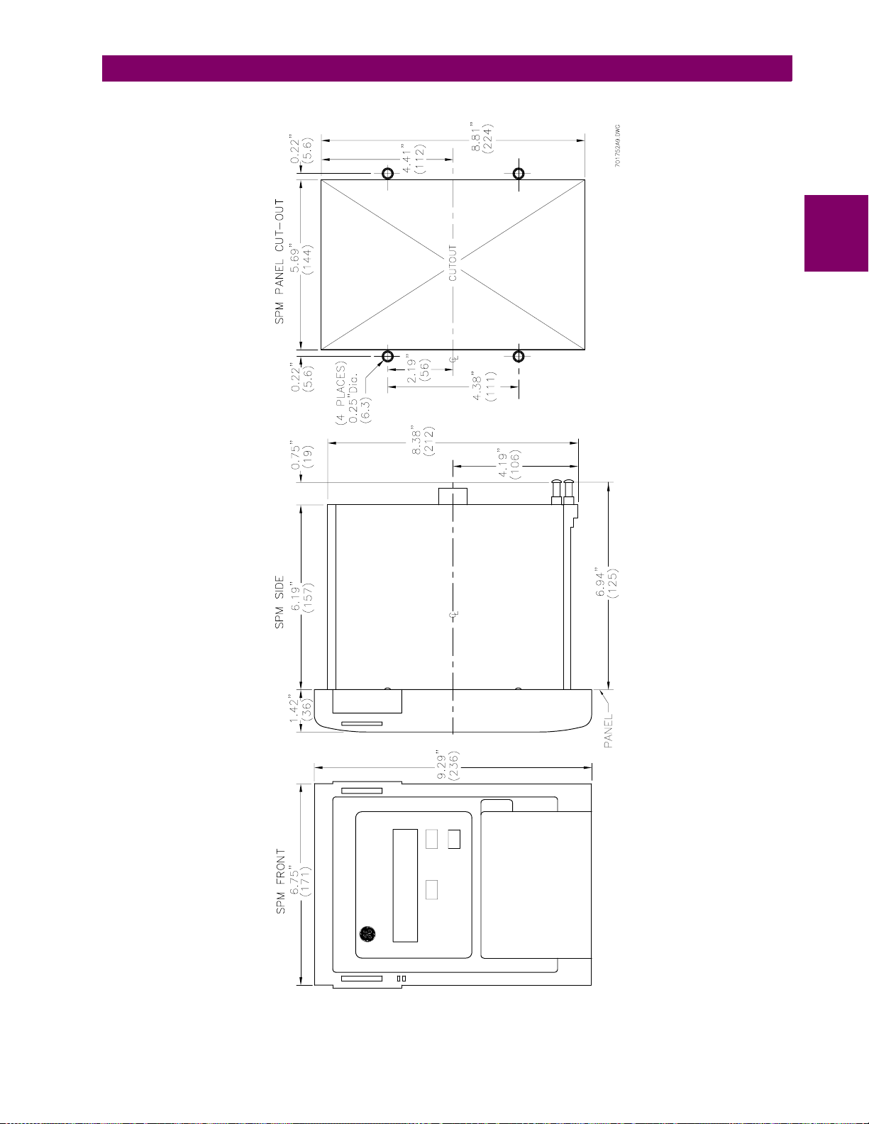
2. Prepare the mounting hole in the panel to dimensions shown in Figure 2–2: PHYSICAL DIMENSIONS.
3. Slide the case into the panel from the front.
4. Install the four mounting scr ews from the re ar of the pane l. The case is now secur ely mounte d and ready
for panel wiring.
2.2.5 SPM MOUNTING ACCESSORIES
See Chapter 8: ACCESSORIES for physical dimensions and mounting requirements.
2-
2
SPM Synchronous Motor Protection & Control GE Power Management
Page 17
2 INSTALLATION 2.2 MECHANICAL INSTALLATION
2
SPM Sync. Protection/Control
Figure 2–2: PHYSICAL DIMENSIONS
GE Power Management SPM Synchronous Motor Protection & Control 2-
3
Page 18
2.3 ELECTRICAL INSTALLATION 2 INSTALLATION
2.3 ELECTRICAL INSTALLATION 2.3.1 DESCRIPTION
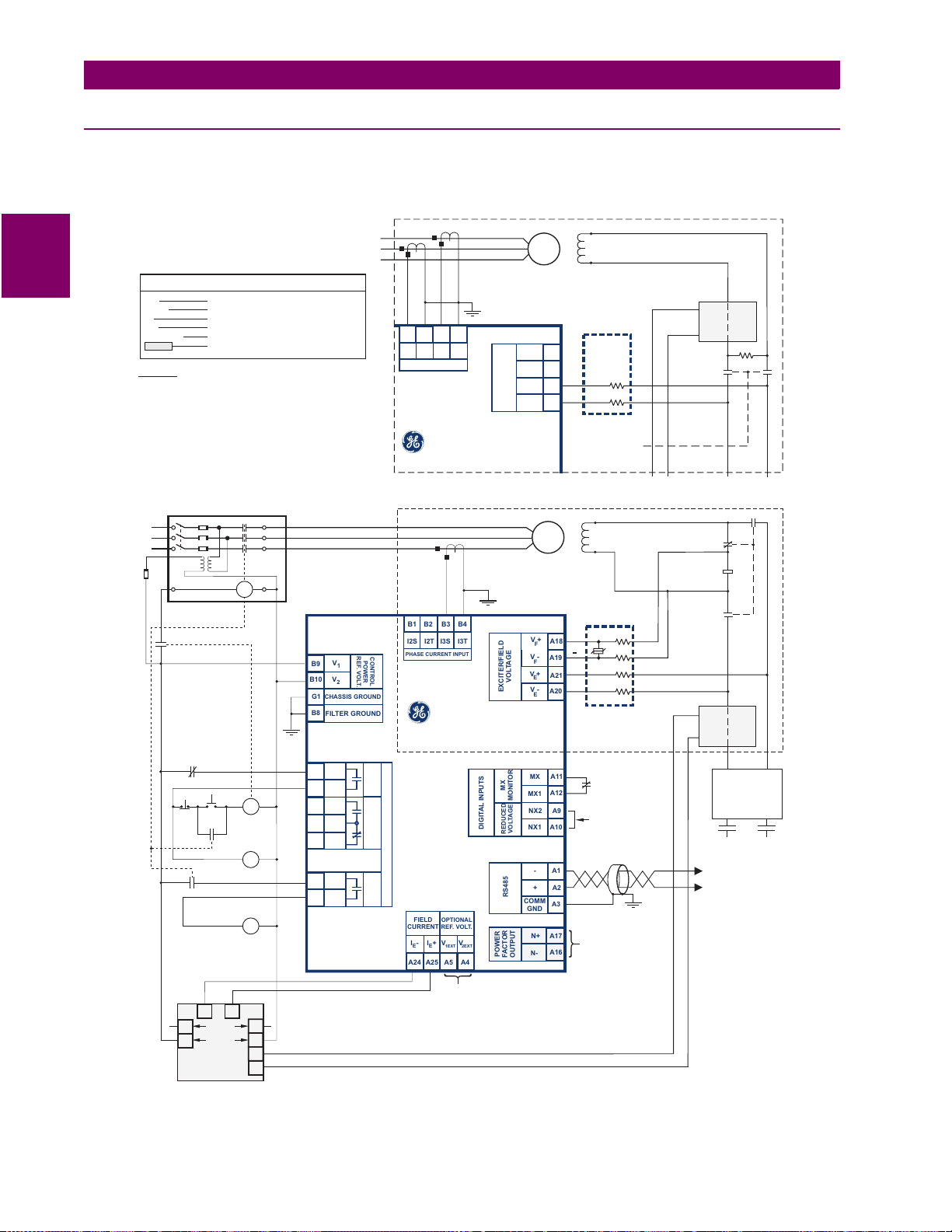
Wire the SPM using one of the following wiring diagrams (one each for brushless, collector ring, and brushless
and collector ring). Pay particular attention to the CT and PT inputs. These inputs must be connected as shown
below for proper power factor protection.
2
NOMENCLATURE
CM
DCCT
M
OL
T1, T2, T3
FIELD CURRENT CALIBRATION MODULE
DIRECT CURRENT CT
MAIN CONTACTOR
OVERLOAD RELAY
MOTOR TERMINALS
OPTIONAL ACCESSORIES
NOTES:
1) Relays shown with no control power applied to relay
*
2) Trip Relay closed during normal operation
TYPICAL BRUSHLESS MOTOR CONNECTION
A
B
C
B1
I2S
PHASE CURRENT INPUT
B2
B3
B4
I3T
I3S
I2T
T1
T2
SYNC
MOTOR
T3
V+
F
V-
F
V+
E
VOLTAGE
V-
EXCITER/FIELD
E
A18
A19
A21
A20
EF1
FIELD
EF2
VOLTAGEDIVIDER
NETWORK (VDN)
(E+)
(E-)
DCCT
(V+)
(V-)
FC FC
R
SUPPLY
A
B
C
STOP
OL
M
START
M
EXCITER
CONTACTOR
FIELD
CONTACTOR
M
MX
MAIN
AUXILIARY
RM
FC
V
B9
1
V
B10
2
G1
CHASSIS GROUND
B8
FILTER GROUND
A23
TRIP1
A22
TRIP2
FCX
A13
N/O
A14
COM
FCX
A15
N/C
FAR 1
A7
FAR 2
A6
GE POWER MANAGEMENT
SPM
TYPICAL COLLECTOR RING MOTOR CONNECTION
T1
T2
SYNC
MOTOR
T3
V+
F
V-
F
V+
E
VOLTAGE
V-
EXCITER/FIELD
E
A18
A19
A21
A20
REF.VOLT.
CONTROL
POWER
PHASE C
B1
B2B4B3
I2S
I3S
I2T
PHASE CURRENT INPUT
GE POWER MANAGEMENT
I3T
SPM
*
(FAR)
(FCX)
TRIP
CONTACTOR AUX.
APPLICATION
FIELD
FIELD
OUTPUT RELAYS
DIGITAL INPUTS
FIELD
OPTIONAL
REF.VOLT.
CURRENT
I+
V
I-
A24
A25
V
2EXT
1EXT
EE
A5
POWER
A4
MX
MONITOR
VOLTAGE
REDUCED
RS485
COMM
FACTOR
OUTPUT
MX
MX1
NX2
NX1
GND
N-
A11
A12
A9
A10
A1
-
+
A2
A3
A17
N+
A16
FIELD CONTACTOR
F1
FIELD
F2
VOLTAGE DIVIDER
NETWORK (VDN)
(+)
()
(E+)
(E-)
M
ON REDUCED VOLTAGE
STARTERS, REMOVE
JUMPER AND CONNECT
A NO. AUX CONTACT
FROM THE FINAL STEP
CONTACTOR HERE.
PF ANALOG OUTPUT OR
PF REG CONTROL SIG
OUTPUT (IF PF
REGULATOR OPTION)
(V+)
(V-)
(R1)
(F2)
7
CM8CM
DISCHARGE
RESISTOR
CONTACTOR
FIELD
FIELD
+
-
DCCTDCCT
EXCITER
V-
FC
FC
V-V-
EXCITER
RM
TO EXCITER
POWER SUPPLY
TO PLC
OR COMPUTER
EXCITER
FC
V+V+
V+
2-
USED FOR SEPARATELY
SUPPLIED POWER FACTOR
65
240 VAC
1
120 VAC
3
FIELD CURRENT
CALIBRATION
MODULE (CM)
2
4
7
8
REFERENCE VOLTAGE
(OPTIONAL CONNECTION)
BRUSHLESS & COLLECTOR RING - 701756AN.CDR
COLLECTOR RING - 701751.DWG
BRUSHLESS - 701753.DWG
Figure 2–3: TYPICAL WIRING DIAGRAM
4
SPM Synchronous Motor Protection & Control GE Power Management
Page 19

2 INSTALLATION 2.3 ELECTRICAL INSTALLATION
1
2
3
4
5
6
7
8
9
10
11
12
13
14
15
16
17
18
19
20
21
22
23
24
25
26
27
28
FRONT VIEW
QUICK RELEASE TABS
Used to remove display for easy
GE KEY
Used to enter or exit the different
modes of the SPM. These are
Standby, Test, Statistics and
Programming modes.
LOCKING PROVISION
A wire lead seal can be used to
prevent unauthorized removal
of relay.
ENTER KEY
Used to make a selection or acts
as an enter key.
DISPLAY FUNCTION MENU
Menu of all accessible setpoints
and actual values for easy reference.
SPM Sync. Protection/Control
ENTER
DISPLAY FUNCTIONS
Items in and white come standard.green
Items in yellow are optional.
Items in green are motor type dependent.
DISPLAY SCROLL SETPOINT SCROLL
AC Amps
Power Factor
DC Amps
DC Volts
(Exciter) Field Ohms
Power Factor Trip
Power Factor Trip Delay
Power Factor Suppression
Power Factor Mode
FAR Delay
FCX Delay
SCROLL
CONTRAST
access to drawout.
LCD DISPLAY
Back lit 32 character display for
setpoints, actual values and status.
Programmable auto scan sequence
for unattended operation.
SCROLL KEYS
Used to scroll through the various
menus and change setpoint
parameter values.
CONTRAST DIAL
Lightens or darkens display.
2
S1 CASE
Compact S1 rugged metal/bakelite
case. Fits standard cutout.
STATSCROLL
Motor Hours
ISP Trip Ctr
FLP Trip Ctr
PO Trip Ctr
Resync Ctr
NO V Trp Ctr
Exc Trip Ctr
PF Trip Ctr
SCP Trip Ctr
FOT Trip Ctr
AC CT Rating
Full Load Amps
Locked Rotor Amps
Sync. Slip
Stall Time
Run Time
DC CT Primary
High (Exciter) Field Ohms
(Exciter) Field Amps
(Exciter) Field Volts
Incomplete Sequence Delay
Regulator Power Factor
Regulator Gain
Regulator Stability
Regulator Output
Regulator Floor Volts
REAR VIEW
F
FCX COM
E
FCX N/C
15
16
TRP1
V+
I+
V-
V+
19
21
23
25
20
22
24
E
E
F
I-
V-
TRP2
FILTER
GND
N+
17
18
N-
1
1
RS485-
2
1EXT
MX
FCX N/O
FAR1
RS485 GND
NX2
V
3
5
7
9
11
4
13
6
8
10
12
14
A
2345678910111213141516171819202122232425262728
NC
A
RS485+
I2S I2T I3S I3T
B
1 23 4 5678910
NX1
2EXT
V
MX1
FAR2
PULLDOWN DOOR
Hides menu when not in use.
TERMINAL BLOCK A
RELAYS
INPUTS
E
NC
27
26
28
NC
NC
V
V
1
2
OUTPUTS
TRIP: Normally open,
failsafe trip relay.
FAR: Field application
relay.
FCX: Autoloading of the
motor.
EXCITER: Exciter voltage
inputs. Connected via
DCCT and CM.
FIELD: DC field voltage
input.
REDUCED VOLTAGE:
Contact input for
reduced voltage starting.
Motor "ON" input.
Exciter current input.
Power Factor reference
voltage (for seperately
powered option).
POWER FACTOR:
0-10VDC analog signal.
MOTOR LINE CURRENT
2 Phase current inputs.
Accept #8 wire.
CONTROL POWER
85 to 265VAC.
701750AF.CDR
Figure 2–4: PANEL AND TERMINAL LAYOUT
GE Power Management SPM Synchronous Motor Protection & Control 2-
5
Page 20

2.3 ELECTRICAL INSTALLATION 2 INSTALLATION
2.3.2 GROUNDING
The SPM relay must be sol idly gro unded to a su itable syste m ground. Ex tensi ve filt ering and tr ansie nt protection has been built into the SPM to ensure proper and reliable operation in harsh industrial environme nts.
Proper grounding of the chassis ground terminal is critical to en-sure safety and filtering.
2.3.3 FIELD AND EXCITER VOLTAGE INPUTS
2
The field voltage i nputs (V
via the supplied voltage divider network (VDN).
DO NOT ATTEMPT TO START THE MOTOR WITHOUT THE EXTERNAL RESISTOR ASSEMBLY
WIRED. SEVERE DAMAGE TO THE SPM MAY RESULT IF THE EXTERNAL RESISTOR ASSEM-
CAUTION
The following is a description of the relay outputs.
1. TRIP: Trip Relay. This relay is normally energized and drops out on loss of power or when the modul e
2. FAR: Field Application Relay. This relay picks up at the proper time to apply DC to the motor field.
BLY IS NOT PROPERLY CONNECTED.
senses an abnormal condition.
+ and VF–) and exciter v oltage in puts (VE+ and VE–) are connected to t he relay
F
2.3.4 RELAY OUTPUTS
3. FCX: Loading Relay. This relay picks up when the motor is fully synchronized and ready to be loaded. It is
controlled by the "FCX Delay" programmable setpoint.
2.3.5 CURRENT TRANSFORMER INPUT
The SPM is designe d to work fro m a fiv e a mpe re (5 A) current trans forme r ( CT) s econdary. The current transformer must be connected i n the prope r motor ph ase. Se e Figur e 2–3: TYP ICAL WI RING DIAGRA M on pag e
2–4 to determine proper phase. For brushless applications, the SPM requires inputs from two motor phases.
2.3.6 POWER FACTOR OUTPUT
This output is a 0 to 10 V DC signal that corresponds linearly to phase shift, and sinusoidal to motor power factor. 0 V is zero lagging power factor, 5 V is unity power factor, and 10 V is zero leading power factor.
Calibration: 1 volt change corresponds to an 18° phase shift (not available with power factor regulation). Do not
connect less than 1000 Ω to this output.
2.3.7 DC FIELD CURRENT INPUT
DC field input must be sensed from a separately purchased DCCT (Direct Current, Current Transformer) and
CM (Calibration Module).
2.3.8 EXCITER VOLTAGE OUTPUT MONITOR
The output of the field exciter must be connected to the SPM through a separate resistor when exciter voltage
failure protection and/or exciter voltage display is required.
2-
6
SPM Synchronous Motor Protection & Control GE Power Management
Page 21
2 INSTALLATION 2.3 ELECTRICAL INSTALLATION
2.3.9 POWER FACTOR REGULATION OUTPUT
This optional output replaces the power factor analog signal output. It consists of a 0 to 10 V DC control signal
which is used to control an SCR Variable Exciter output to obtain motor power factor regulation.
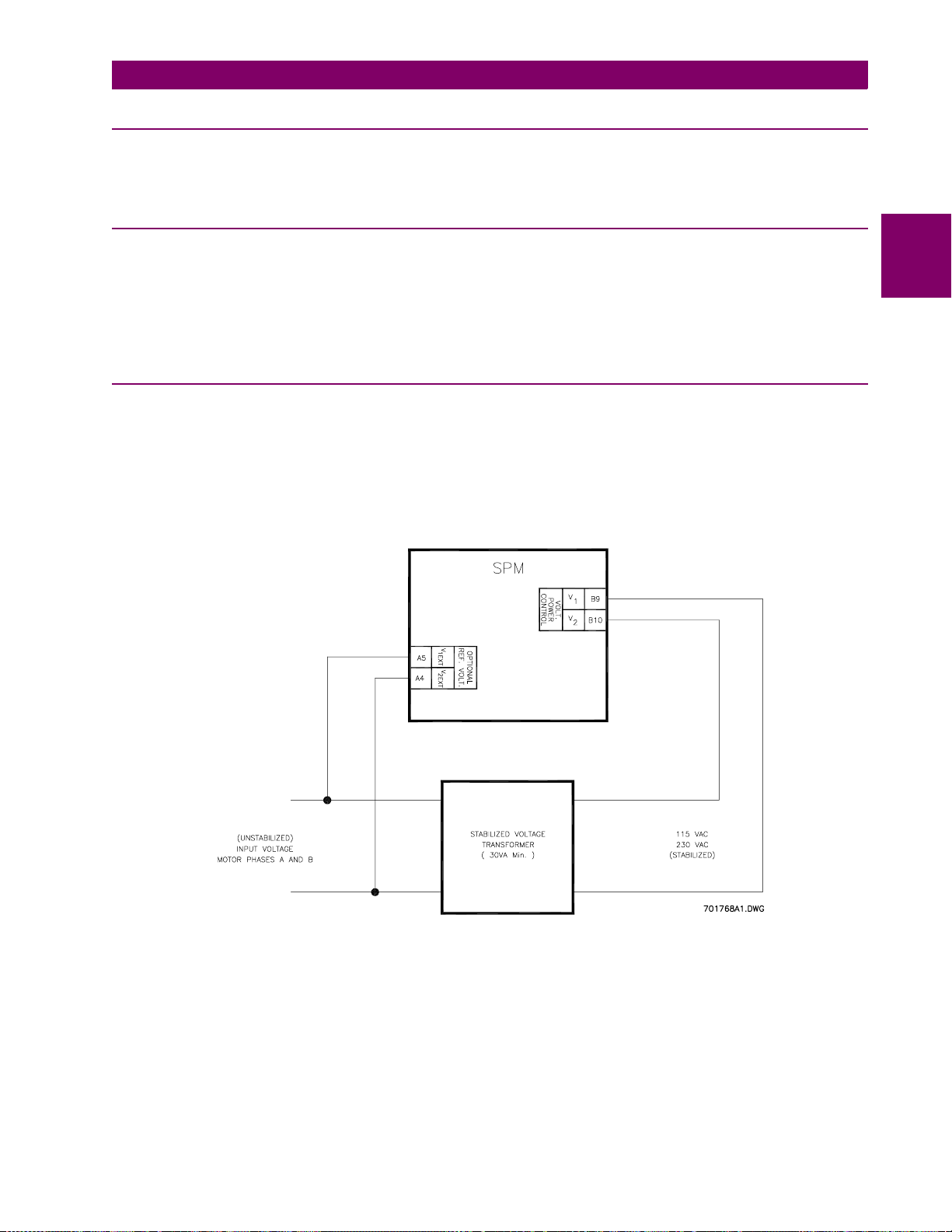
2.3.10 CONTROL VOLTAGE
If control voltage ex cursions occur ou tside the r ange of 85 to 265 VAC, a p rovision is avai lable that will allow
the user to connect a n external stabilizing transf ormer for operation with sev ere control power voltage di ps.
The SPM has separate inputs for control power and power factor reference voltage. This allows connection for
control power from a stabi lized vol tage sour ce of 115 V AC or 230 V AC . Terminal points "V
1EXT
" and "V
2EXT
have been added to accommodate the separate PF reference voltage.
2.3.11 EXTERNAL VOLTAGE PF REFERENCE
When terminal poi nts "V
1EXT
" and "V
" are used to accommod ate a separate PF reference voltage, as
2EXT
described above, a s tandard p rotective function wil l alert the user sho uld this external voltage d rop below th e
acceptable limits for the SP M power s upply. This protection will not allow th e motor t o start while the external
voltage is missin g, bu t the SP M will no t re qui re a r es et befo re the moto r can be restarted. If the exter nal refer ence voltage is lost while the moto r is running, the SPM will trip the motor and will require a r eset before the
motor can be restarted. "MISSING VOLTAGE!" will be displayed until reset.
2
"
Figure 2–5: REFERENCE VOLTAGE INPUT CONNECTIONS
GE Power Management SPM Synchronous Motor Protection & Control 2-
7
Page 22
2.3 ELECTRICAL INSTALLATION 2 INSTALLATION
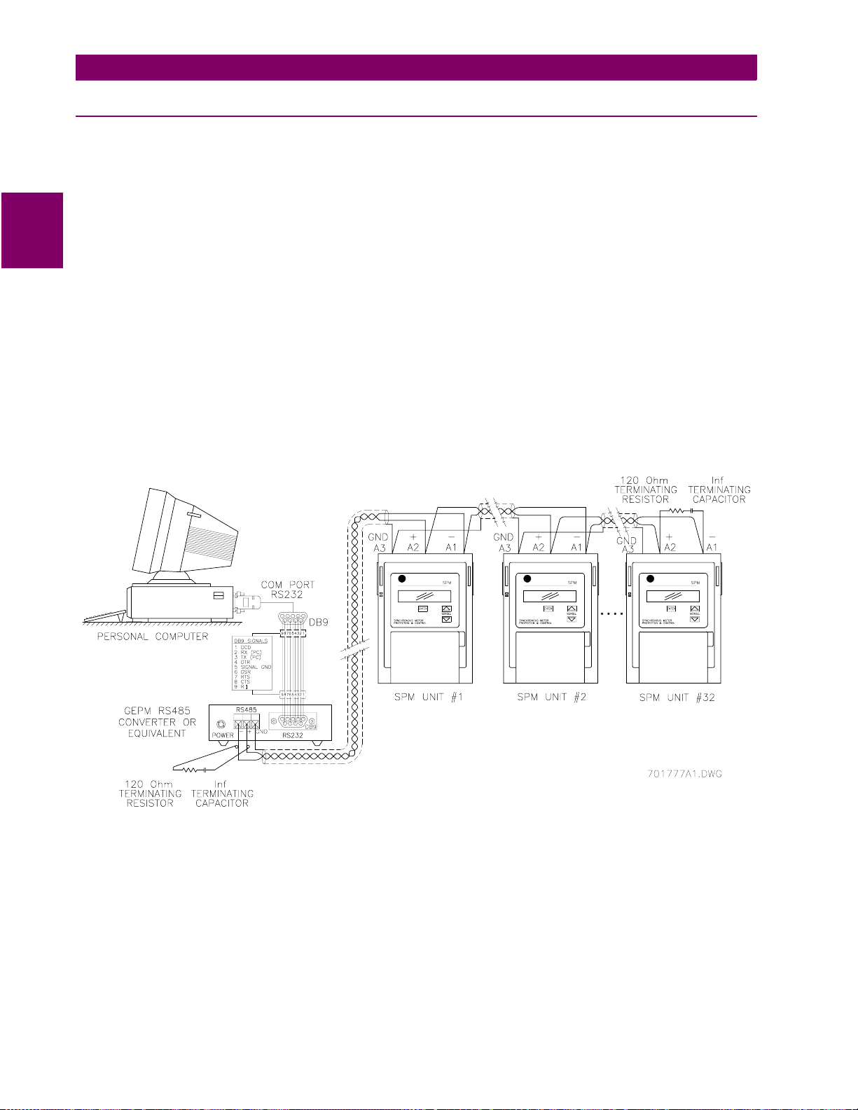
2.3.12 RS485 COMMUNICATIONS PORT
One two-wire RS485 po rt is provided. Up to 32 SPMs can be da isy-chained together on a communica tion
channel without excee ding the driv er ca pabil ity. For larger systems, additiona l serial channels mu st be added.
It is also possible to use commercially available repeaters to increase the number of relays on a single channel
to more than 32. Suitable cable should hav e character istic impe dance o f 120Ω (e.g. Belden #9841) and total
wire length should no t exceed 400 0 ft. Commercial ly available repeaters wil l allow for trans mission distanc es
greater than 4000 ft.
2
Voltage differences between remote ends of the communication link are not uncommon. For this reason, surge
protection device s are internally install ed across all RS485 term inals. Internally an iso lated power supply is
used to prevent noise coupling. To ensure that all devices in a daisy-chain are at the same potential, it is imperative that the common ter minal s of eac h RS485 por t are tied to get her and gr ounded only once , at the ma ste r.
Failure to do so may result in intermittent or failed communications. The source computer/PLC/SCADA system
should have similar tr ansient protection devices insta lled, either internally or externally, to ensure maximum
reliability. To avoid ground loops, ground the shield at one point only as shown below.
Correct polarity is also essential. SPMs must be wired with all '+' terminals connected together, and all '–' terminals connected together. Each relay must b e dai sy -ch ain ed to th e next on e. Avoid star or st ub c onne ct ed c onfigurations. The last device at each end of the daisy chain should be terminated with a 120Ω, ¼ watt resistor in
series with a 1 nF capacitor across the '+' and '–' termi nals . Observi ng thes e guidel ines will res ult in a r eli able
communication system immune to system transients.
2-
Figure 2–6: RS485 WIRING
8
SPM Synchronous Motor Protection & Control GE Power Management
Page 23
3 SYNCHRONOUS MOTOR APPLICATIONS 3.1 OVERVIEW
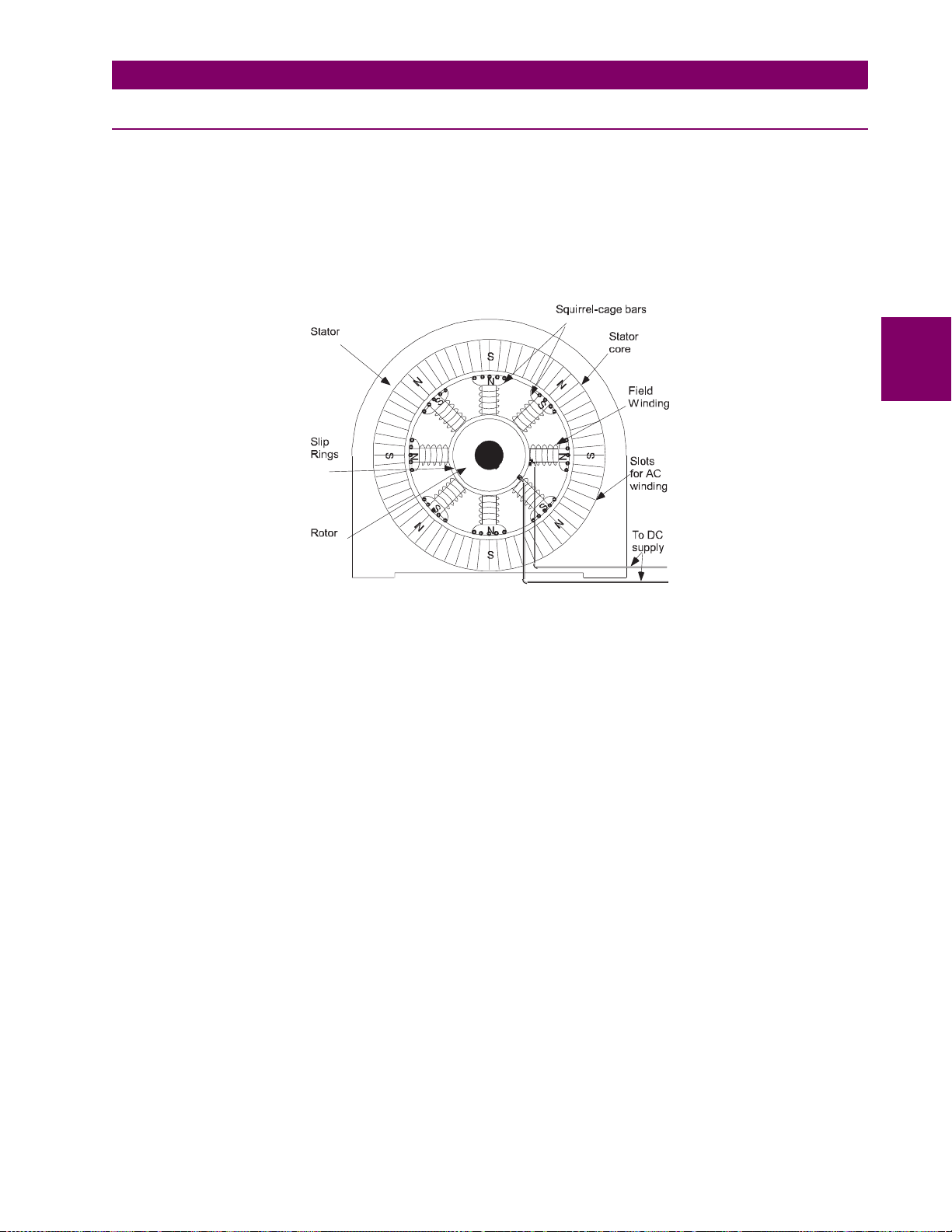
3 SYNCHRONOUS MOTOR APPLICATIONS 3.1 OVERVIEW 3.1.1 GENERAL
The most attractive and widely applied method of starting a synchronous motor is to utilize squirrel cage windings in the pole faces of the synchronous motor rotor. The presence of these windings allows for a reaction (or
acceleration) torque to be dev eloped in the rotor as the AC excited stator windings induc e current into the
squirrel cage windings . Thus, the synchronous motor starts as an induction motor. These rotor windings are
frequently referred to as damper or amorti sseur windings. The other major function of these winding s is to
dampen power angle oscillations after the motor has sync hronized. Unlike induction motor s, no continuous
squirrel cage torque is developed at normal running speeds. Examine the figure below:
3
Figure 3–1: SALIENT POLE SYNCHRONOUS MOTOR
When the motor accelerates to near synchronizing speed (about 95% synchronous speed), DC current is introduced into the rotor f ield winding s. This c urrent create s const ant polar ity pole s in the roto r, causing the motor
to operate at synchronous speed as the rotor poles "lock" onto the rotating AC stator poles.
Torque at synchronous speed is derived from the magnetic field produced by the DC field coils on the rotor linking the rotating field produced by the AC currents in the armature windings on the stator.
Magnetic polariza tion of the r otor iron i s due to the rotor ’s physical sha pe and arrang ement and the constant
potential DC in coils looped around the circumference of the rotor.
Synchronous motors possess two general categories of torque characteristics. One characteristic is determined by the squirrel- cage design, which prod uces a torque in rel ation to "slip" (some spe ed other than synchronous speed). The other char acteristic is d etermined by the flux in the s alient field pol es on the roto r as it
runs at synchronous speed. The first characteristic is referred to as
istic is usually referred to as
In starting mode, the syn chronou s motor sali ent pol es are not ex cite d by their external DC sour ce. At temptin g
to start the motor with DC applied to the field does not allow the motor to accelerate. In addition, there is a very
large oscillating to rque component at sl ip frequency, produced by field excitation, wh ich could result in motor
damage if full field curre nt is applied during the entir e starting sequence. Th erefore, application of DC to th e
field is usually delayed until the motor reaches a speed where it can be pulled into synchronism without slip.
At synchronous speed, the ferro-magnetic rotor poles become magnetize d, resulting in a small torque (reluctance torque) which enab les the motor to run at very l ight loads in synchronism without external excitation.
Reluctance torque can also pull the motor into step if it is lightly loaded and coupled to low inertia.
synchronous torque
.
starting torque
, while the second character-
It is convenient to make an analogy of a synchronous motor to a current transformer for the purpose of demonstrating angular relationship of field current and flux with rotor position.
GE Power Management SPM Synchronous Motor Protection & Control 3-
1
Page 24
3.1 OVERVIEW 3 SYNCHRONOUS MOTOR APPLICATIONS
If
I
is an equivalent current in the st ator causi ng the tra nsformer a ction, then
1
I
), and the flux w il l be 90° behind
FD
as the induced field current
rent. See the figure below.
3
I
will be about 180° fr om
I
. Very significantly, then, the poin t of maxim um-i nduce d flux (Ø) oc curs
I
FD
FD
passes through zero from negative to positive; maximum rate of change of cur-
1
I
2
(or
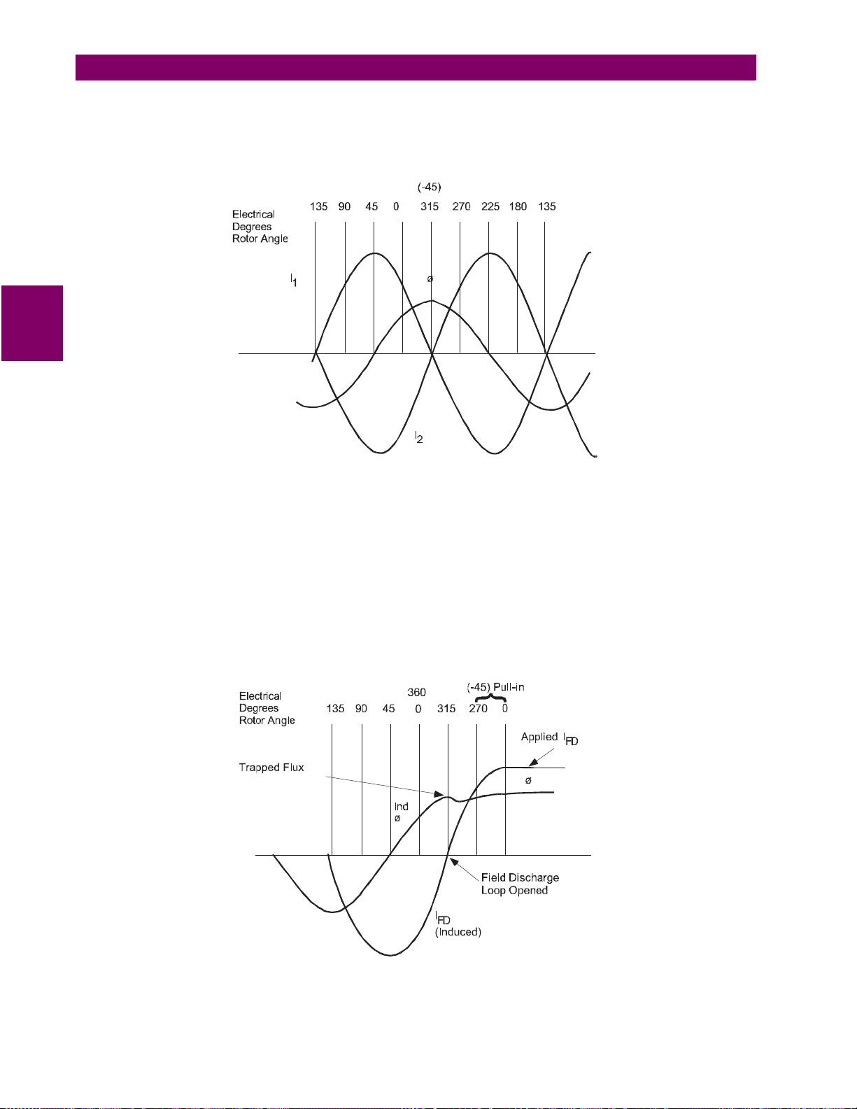
Figure 3–2: TYPICAL TRANSFORMER ROTOR FLUX AND CURENT (CONSTANT SLIP)
The rotor angle at which
I
1
and
I
go through zero depe nds upon the reactance-to -resistanc e ratio in the field
2
circuit. A very high v alue of reactance-to-resistance shifts the angle toward –90°. Re actance is high at low
speed (high frequen cy). At high speed (low slip, l ow frequency), reactance decrease s and the angle shifts
toward 0° if the circuit includes a high value of resistance. As the stator goes beyond –45°, the torque
increases (due to increased stator flux ). At this point,
I
yields a convenient in dicator of maximum flux an d
FD
increasing torque from which excitation is applied for maximum effectiveness.
If the field discharge loop is ope ned at the poi nt of m ax im um flux , thi s f lux is "t rappe d." App ly ing ex ter na l exc i-
tation in correct polarity to increase this trapped flux at this instant makes maximum use of its existence. At this
point the stator p ole ha s jus t mov ed by an d is in po sitio n to pu ll the roto r for ward int o sy nchr onous align ment.
See the figure below.
3-
Figure 3–3: TYPICAL ROTOR FLUX AND CURRENT AT PULL-IN
2
SPM Synchronous Motor Protection & Control GE Power Management
Page 25
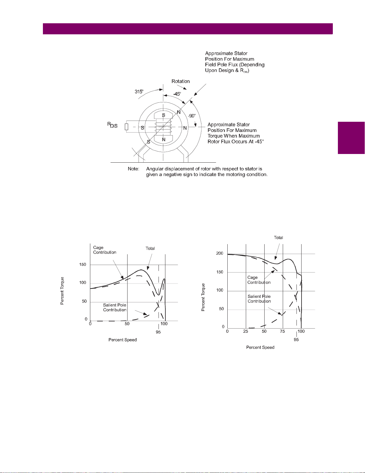
3 SYNCHRONOUS MOTOR APPLICATIONS 3.1 OVERVIEW
Figure 3–4: ANGULAR DISPLACEMENT OF ROTOR
It has been established that salient-pole torque near synchronous speed is a function of both slip and field-discharge resistance. The combi ned e ffects of c age to rque and sal ient p ole tor que for a ty pical m otor a re show n
below. The effect of a higher value of discharge resistan ce on a me dium-tor que mot or are sho wn in Figure 3–
6: FIELD DISCHARGE RESISTANCE – MEDIUM STARTING TORQUE. Obviously, without salient-pole torque
the motor would cease to accelerate certain loads at some point on the speed axis.
3
HIGH-STARTING-TORQUE MOTORMEDIUM-STARTING-TORQUE MOTOR
Figure 3–5: MOTOR TORQUE VS. SPEED
The upper limit of t he dischar ge res ista nce i s gover ned b y the other fu nctio n o f the resist or, which is reduc ing
field voltage to saf e le ve ls dur i ng st arti ng. A s the d is ch arge r es i sta nc e in cr ea se s s o d oes the ind uc ed v ol tage ,
and at some poin t this voltage would be damag ing to insula tion o r oth er com pone nts in the fie ld c ircuit. Solidstate excitation a nd control components in the fiel d circuit have had the effect of makin g the disc harge resi stance and its voltage effect mor e signifi cant. There i s a grea ter sens itiv ity to fie ld vol tage to leran ce le vels wit h
solid-state components.
GE Power Management SPM Synchronous Motor Protection & Control 3-
3
Page 26

3.1 OVERVIEW 3 SYNCHRONOUS MOTOR APPLICATIONS
3
Figure 3–6: FIELD DISCHARGE RESISTANCE – MEDIUM STARTING TORQUE
Selection of the value of the field discharge resistance is a decisi on that may r equire judici ous applica tion of
several factors present on a particular drive, such as torque, excitation systems, and control components.
The importance of speed for app lying field cannot be over-emphasized. Rotor and load masses cannot be
accelerated fast enough to allow synchronization, if slip is in excess of ten percent.
Synchronous-motor controllers which can acc urately apply field at an optimum speed and a favor able angle
permit matching the motor to the load with a greater degree of precision than might otherwise be possible. The
increase in load w hich can be pulled in due to preci sion applic ation of fie ld will va ry from one m otor design to
another along with system inertia.
Applying excitation at the point of zero induced current (favorable angle) takes advantage of motor capability in
two ways:
1. It catches (“traps”) salient- pole flux at s ignificant ma gnitude (p rovided ther e is a field di scharge re sistor of
adequate value) and uses it for torque during a 180° acceleration period.
2. It catches the rotor in correct angular position to be pulled forward into step.
In addition to permitting closer matching of motor to load, optimum application of excitation also reduces power
system disturbance w hich o ccurs when th e motor go es thr ough a comp lete sli p cycle with the fi eld en ergized .
If the motor is large relative to the power system, surges transmitted to the system will be at a minimum if field
is applied to prevent slip at pull-in.
3-
4
SPM Synchronous Motor Protection & Control GE Power Management
Page 27

3 SYNCHRONOUS MOTOR APPLICATIONS 3.2 COLLECTOR-RING MOTORS
3.2 COLLECTOR-RING MOTORS 3.2.1 STARTING AND SYNCHRONIZING
Control functions for starting the synchronous motor include the following:
• Applying power to the stator; at full voltage or reduced voltage.
• Shunting the field with a discharge resistor (FDRS).
• Sensing rotor speed.
• Sensing rotor angle.
• Applying excitation at optimum speed and angle.
• Reluctance torque synchronizing.
The first step in starting a synchronous motor is to apply power to the stator by means of a magnetic contactor
or circuit breaker.
Shunting a resistor around the motor field during starting is accomplished with a field contactor. Optimum appli-
cation of excitation (that is, closing the field c ontactor) requires accurate sen sing of motor speed and rotor
angle. This SPM pro vides this functi on. Optimum spee d for pull-in var ies with motor d esign and with the field
discharge resisto r val ue. A dju st men t of the c ontrol to app ly fiel d at v ario us v al ues of mot or spe ed is important.
The correct rotor angle for fiel d application does not vary and is always the po int where induced field cu rrent
passes through zero goi ng f rom ne gative to positive – the poi nt o f ma xi mu m r oto r flux ( see Figure 3–3:: TYPICAL ROTOR FLUX AND CURRENT AT PULL-IN on page 3–2). Maximum utilization of motor pull-in capability
depends upon the degree to which the control can accurately sense speed and rotor angle.
Rotor frequency is th e mo st pos iti ve el ec tr ical parameter available for in dica t ing sp eed , and ca n be s en se d by
detecting the frequency of the voltage across FDRS . Voltage across FDRS is not actually "induced field voltage," but is the volta ge which is essenti ally in time phase relation to the curr ent through the re sistor. That is,
the current goes through zero at the same time the voltage goes through zero.
The SPM detects the proper rotor speed (PRS ) and rotor angle (PRA) signal, implemente d in the Field Programmable Gate Array (FPG A). Outputs fr om the PRS and the circuits are used to de termine the proper time
to close the Field Appli cation Relay (FAR), based on the pe rcent synchrono us slip setpoi nt. When the pro per
rotor speed and the proper rotor angle conditions are met as determined by the FPGA, the CPU delivers a signal to the FAR Relay so it can close its contact FAR1-F AR2. FAR picks up field contactor FC to apply excitation
to the motor field and to o pen the fie ld d isc har ge resi st or loo p. S ee Figu re 2–4 : PANEL AND TERMINAL LAYOUT on page 2–5 for details. The speed at which the motor is to synchronize (PRS) can be programmed from
90 to 99.5% of synchronous speed.
3
GE Power Management SPM Synchronous Motor Protection & Control 3-
5
Page 28
3.2 COLLECTOR-RING MOTORS 3 SYNCHRONOUS MOTOR APPLICATIONS
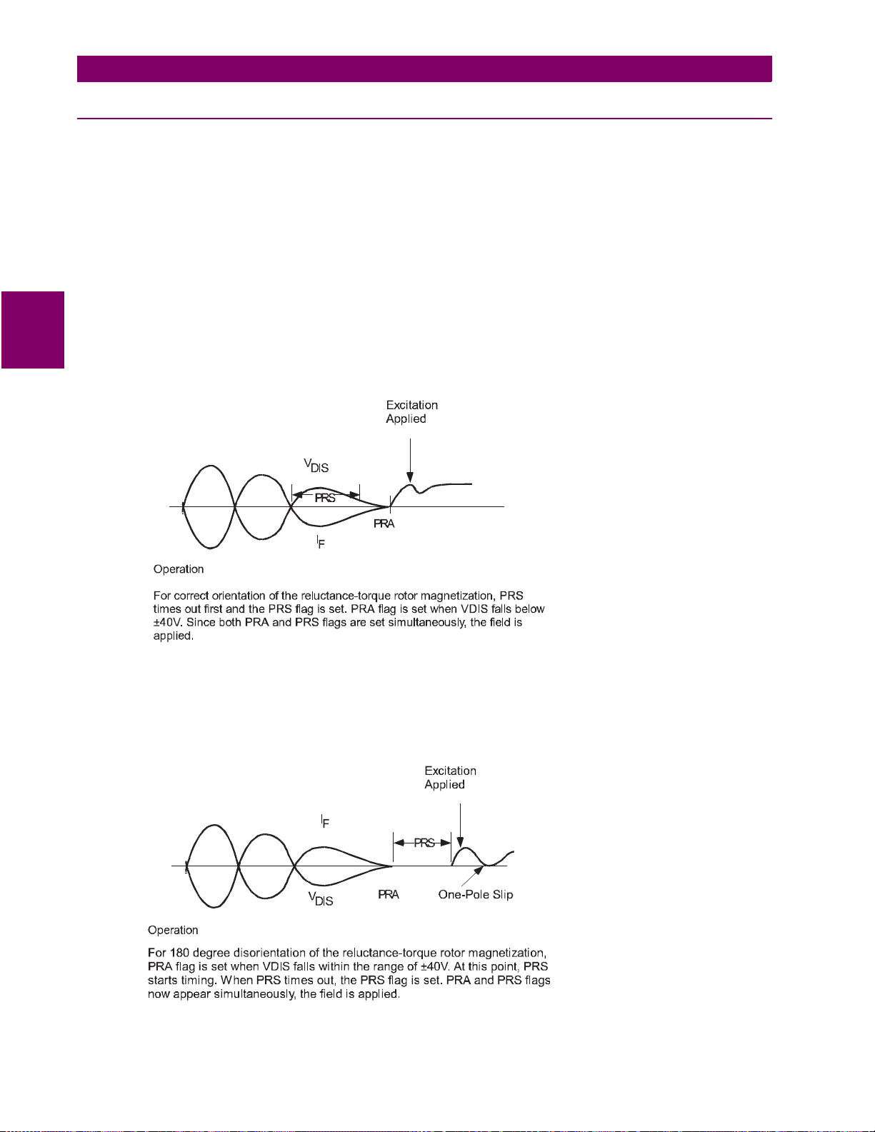
3.2.2 RELUCTANCE TORQUE SYNCHRONIZING
A lightly loaded syn chro nou s m otor c onn ected to a low inertial load may pul l i nto sy nc hroni s m be fore the rotor
poles are externally magnetized. This is commonly known as reluctance torque synchronizing. This magnetization can result in su fficient torque to hol d the salient poles in direct align ment with corr esponding st ator poles
and run the motor at sy nchronous speed. However, when load is applied, th e rotor begins to slip since th e
torque developed is o nly a fraction of rate d torque under sep arate excitation. Fu rthermore, the rotor is polarized by the stat or flux u nder this condition and can therefore be polar ized in a ny direc t axis al ignment; occurring each 180°. External excitation forces pole-to-pole alignment in only one orientation of the direct axis.
Should the rotor pull in to syn chronism 180° away from the normal running al ignment, external ex citation will
build up rotor flux in opposition to the stator flux. As the external excitation builds up, correct alignment of rotor
to stator occurs by slipping one pole and the motor will then run in normal synchronism.
3
The Field Application Control must respond in such a way as to proceed with proper application of excitation in
the event the motor does synchronize on reluctance torque. The following diagram demonstrates how the SPM
automatically responds to reluctance torque synchronizing.
CORRECT
ORIENTATION
180°
DISORIENTATION
3-
Figure 3–7: RELUCTANCE TORQUE MOTOR MAGNETIZATION
6
SPM Synchronous Motor Protection & Control GE Power Management
Page 29

3 SYNCHRONOUS MOTOR APPLICATIONS 3.2 COLLECTOR-RING MOTORS
3.2.3 STARTING PROTECTION
The amortisseur, or cage winding of a synchronous motor, is probably the element most susceptible to thermal
damage. Its function is essen tially operative onl y during starting, a nd there are limitations on sp ace available
for its construction on to the rotor. Hence, it is usually made of lighter material than the cag e winding of an
induction motor. The cage is also vulnerable to overheating should the motor be allowed to run out of synchronism with no excitation. In this case, it runs as an induction motor at some value of slip which will produce cage
current that develops r unning torque . However, the cage of a synchronous m otor is not designed for continuous operation. Theref ore, an important protective function of t he controller is to prevent overheating o f the
cage winding both during starting and running out of synchronism.
Monitoring the starting c ondition of a sync hronous motor can be accom plished by lookin g at the frequency of
induced field current, the same procedure used to ac complish sy nchroniz ing. Motor desig ners always plac e a
limit on the time a particul ar motor can be allowed to remain stalled (" allowable stall time"). An acceler ated
schedule can then be established for the motor in terms of running time at any speed less than synchronous as
a percent of allowab le stall time. Increased air circulation from th e rotor fan reduces the heating rate as the
motor accelerates . Frequency can b e measured d irectly as an indication of s peed, and the des igner's curves
for speed versus time c an be used for protection by softwa re that in tegrates the time-speed function. The figure below shows the typical cage heating protection characteristics during acceleration.
The time-speed functi on show n in belo w is d etermine d inter nally b y SPM s oftwar e. The mo tor spee d is d etermined from the induced field voltage frequency. The programmed values for maximum allowable stall time and
50% speed run time determine which characteristic of protection is required from the family of curves.
3
The SPM will cause a TRIP operation and display "SQL CAGE TRIP" if it calculates that the thermal limit of the
cage winding is reached. The SPM will also p revent an attempted restart if it calculates, from lear ned start
experience, that the cage winding has not had sufficien t cooling time to allow a su ccessful st art. In this case
the message "START INHIBITED! Ready in xxx min" will be displayed
200
150
100
80
60
50
40
30
25
20
15
10
Run Time
Allowable Zero Speed Stall Time
1.5
8
6
5
4
3
2
3
2.05
1.46
1.05
0
0
.
1
0
10 20 60 90 1008070504030
% Synchronous Speed
701761A7.CDR
Figure 3–8: AMORTISSEUR WINDING PROTECTION
GE Power Management SPM Synchronous Motor Protection & Control 3-
7
Page 30

3.2 COLLECTOR-RING MOTORS 3 SYNCHRONOUS MOTOR APPLICATIONS
3.2.4 REDUCED VOLTAGE STARTING
Many synchronous mot or starti ng applications involve either reduced voltage (starting reactor or autotransformer) or part-winding star ting me thods. When these m ethods are use d, the avail able torq ue for ac celera tion
is reduced from the torque that would result from a full-voltage start. Also, the allowable stall time of a motor is
extended during a reduced-voltage start due to the reduced heating-rate resulting from lower inrush currents.
The SPM has the abilit y to take advantage of the motor's extended st all time so that the mot or and load can
accelerate to synchrono us speed in a time period longer than would be allowed with a full volta ge start. The
acceleration torque is reduced as the square of the ratio of reduced voltage to full voltage, and the motor-heating rate is proportional to the square of the starting current. Si nce the motor inr ush current i s reduced p roportionally with the voltage reduction (due to the constant impedance of the synchronous motor at stall) the
following allowable stall time factor applies:
3
2
I
PLR
----------- -
I
MLR
where:
I
= programmed full voltage locked rotor current.
PLR
I
= measured inrush current.
MLR
This ratio can be used as a factor for increasing the stall time above the full voltage allowable stall time for any
given speed. See Figure 19.
The SPM calculates the ratio, squares it, and factors this value into the stall time algorithm approximately onetenth of a second after m otor star ts. When the fin al ste p conta ctor cl oses and appli es ful l voltage to the mo tor
windings, a N.O. interlock from this contactor is wired to the SPM to signal that the motor is now at full voltage.
The correction factor for reduced voltage starts then immediately becomes unity.
If, for any reason, it is not desirable to have this ratio correction factored in , a jumper may be placed ac ross
inputs NX1 and NX2. Conver sely, if the motor is star ted from a weak s ystem, and signific ant vol tage dips are
expected during starting , the factory jumper from NX1 to NX2 may be remove d. The SPM will automatical ly
extend the stall and accelerating time per the reduced voltage factor.
To find the protective characteristic used, plot the programmed value for 50% run time and
draw in the complete curve through the plotted point using the above curves as a guide.
NOTE
The curves shown in the following diagram demonstrate how the trip characteristic of the
amortisseur winding protection is adjusted for reduced voltage starts. For this example, curve
NOTE
1 is taken from one of the family of curves in Figure 3–8: AM ORTISSEUR WINDIN G PROTECTION on page 3–7.
3-
8
SPM Synchronous Motor Protection & Control GE Power Management
Page 31

3 SYNCHRONOUS MOTOR APPLICATIONS 3.2 COLLECTOR-RING MOTORS
200
150
100
80
60
50
40
30
25
20
15
Run Time
10
8
Zero Speed Stall Time
Line
6
Voltage
5
50%
4
3
65%
2
80%
1.5
90%
100%
1
0
10 20 60 90 1008070504030
% Synchronous Speed
701760A7.CDR
3
Figure 3–9: PROTECTION FOR REDUCED VOLTAGE STARTS
GE Power Management SPM Synchronous Motor Protection & Control 3-
9
Page 32

3.2 COLLECTOR-RING MOTORS 3 SYNCHRONOUS MOTOR APPLICATIONS
3.2.5 POWER FACTOR (PULL-OUT) PROTECTION
Synchronous motors are designed to run at constant speed and drive shaft loads from torque derived from the
magnetic poles on thei r roto rs m agnetica lly linking oppos ite s tator pole s. W heneve r the rotor turns a t a spee d
less than that of st ator rotating fi eld, the motor is said to be s lipping poles . Slip can occ ur with the field poles
magnetized while running in synchronism from the following four major causes.
1. A gradual increase in load beyond the pull-out capabilities of the motor.
2. A slow decrease in field current.
3. A sudden large impact load.
4. A system fault or voltage dip lasting long enough to cause pull-out.
Loss of synchronism with field applied will create intense pulsations in torque at the motor shaft each time a
3
stator pole passes a rotor pole. Corresponding pulsations occur in line current. Both types of pulsations can be
damaging. Torque puls ations can break a shaft, coup ling, or other mechanical el ements, and current pulsations can interfere with smooth p ower system o peration. Slip ping pole s with field applied is alwa ys unacce ptable for a synchronous motor, therefore some means must be provided to prevent this condition from
occurring.
One of the most reliable indicators of synchronous and asynchronous (out-of-step) operation is the motor
power factor. Power factor is related to the phase angle between voltage and current. Synchronous motors seldom, if ever, operate continuously at lag ging power factor. Synchronous motors run at either un ity or some
value of leading powe r factor. Lagging power fac tor appears when the motor load angle increas es beyond
rated, becoming almos t fully lag ging (90°) as the motor slips out-of-step. Th erefore, la gging power fa ctor can
be utilized to initiate action to prevent slipping.
Torque and power pulsations during slip can be reduced by removing field current to the rotor poles. The motor
will then run essentially as an induction motor on its amortisseur winding. Slip with the field current removed is
tolerable to the load and power syste m but intolerabl e for any length of time to the motor amortis seur windin g
itself, since the winding is desi gned with limited thermal capab ility and for short-time operatio n. Motor Power
Factor during inductio n motor operat ion (that is with field r emoved) is always laggi ng. However, the degree to
which the current la gs the voltage is less th an at pull-out when fiel d poles are excited. Lagg ing power factor
can again be utilized as an indicator of "slip" during induction motor operation.
For synchronous motors , power-factor monitoring can b e employed to guard against pul l-out or loss of field
conditions.
3-
10
SPM Synchronous Motor Protection & Control GE Power Management
Page 33

3 SYNCHRONOUS MOTOR APPLICATIONS 3.2 COLLECTOR-RING MOTORS
3.2.6 POWER FACTOR OPERATION
Motor pull-out pro tection is provid ed by a circui t which monitors po wer factor and has a built-in t ime delay to
prevent inadvertent tripping on transients. The SPM sens es power factor by monitoring the voltage across
motor Phases One and Two and the current in Phase Three. Figure 20 is a phasor diagram depicting the relationship of voltage and current for various power factors.
The SPM automatically suppresses power factor protecti on until the programmed setpoin t "FCX" times out.
The SPM can be programmed to suppress power factor trip action if the line current is less than 6 percent or 50
percent of the rated full load current via the PF Suppression setpoint. Selecting the "Ridethru" mode for the PF
Mode setpoint places the SPM into ride-through mode. Selecting the "Re-sync" mode for the PF Mode setpoint
places the SPM into resync mode. These modes are described in the next section.
3
Figure 3–10: POWER FACTOR SENSING EXAMPLE
GE Power Management SPM Synchronous Motor Protection & Control 3-
11
Page 34

3.2 COLLECTOR-RING MOTORS 3 SYNCHRONOUS MOTOR APPLICATIONS
3.2.7 CONTROLLER ACTION DURING PULL-OUT
If excessive mechani cal load is applied to the mo tor shaft dur ing normal ru nning of the moto r in synchr onism,
the resulting lagging pow er fact or and/or l ine current surge will be detec ted by the S PM. Two forms of pull-out
protection are available. They are as follows
a) RESYNC MODE
Resync mode operation ca uses the Field Appli cation Relay, FAR, to remov e the motor-field ex citation. Actio n
will occur from either lagging power factor below the programmed setpoint or a line current surge above
approximately four times motor full-load current.
Relay FCX drops out at the same time as FAR. Load is removed if an automatic loader is connected.
The motor will continue to r un with field removed for the programmed power factor dela y time, and if resyn-
3
chronization does not occur within this time, the TRIP relay will operate and the motor will stop.
The display will indicate "FAIL TO RESYNC!"
b) RIDE-THRU MODE
If the alternate "ride-thru" mode is selected, the field is not removed immediately as in the resync mode.
Instead, if the power factor dips below the trip point and persists for the PF time delay, the TRIP relay will oper-
ate and the motor will sto p. A l so, a li ne cu rren t s ur ge grea ter th an appr oxi mate ly fo ur ti mes m oto r ful l loa d will
cause TRIP operation i f the PF time delay is exceeded. Power fac tor trips are indicated by "PW R FACTOR
TRIP!" in the displ ay. Line current surges greater than four tim es rated line current are indicated by "PULLOUT TRIP!".
3-
12
SPM Synchronous Motor Protection & Control GE Power Management
Page 35

3 SYNCHRONOUS MOTOR APPLICATIONS 3.2 COLLECTOR-RING MOTORS
3.2.8 EFFECT OF VOLTAGE DIPS ON MOTOR POWER FACTOR
Solid-state excitation systems have an effect on the way motor power factor responds to line voltage dips. The
effect may be to cause a power-factor relay to operate ina dvertently. This causes the motor to trip on laggin g
power factor caused by a transient condition which is not an actual pull-out condition.
A solid-state ex ci ter d iffers fr om a r otat ing ex cite r in th e wa y it responds to vo lta ge di ps. T he r ota ting i ner tia of
a Motor-Generator set may maintain excitation voltage relatively constant for several seconds, but a solid-state
exciter has practically no built-in delay in the way it responds to line voltage. Therefore, any delay in change of
motor-rotor flux fo llowing an excitation voltage cha nge is determined by the tim e constant of the rotor field
poles themselves. This is usually 0.5 to 1.0 seconds.
The sequence of even ts transpiring during a voltage dip with a solid-state exciter is show n in Figure 3–11:
POWER FACTOR RESPONSE TO LINE VARIANCE on page 3–14.
Assuming the cond ition of a line voltage decrease o f 15% with the motor initially a t unity power factor, the
power factor w ill swing leading momentarily because the generat ed EMF d oes not c hange unti l the rot or flux
decreases (determined by field time constant). The motor will tend to maintain constant horsepower by slightly
increasing line curre nt. As the field flux decrea ses, generated EMF als o decreases, and the power fac tor will
move back towards un ity, and there will be a load an gle in crea se to pe rmit motor tor que to b e res tored to that
required to drive the load. During both of these sequences the motor power factor has not become significantly
lagging, so the power-factor relay does not operate.
Finally, when line voltage comes back to normal, th e power factor will momentaril y swing over to lagging and
the power factor prote ction relay will trip because th e rotor flux does n ot respond a s rapidly to chan ge as the
stator. The generated EMF is low relative to line volts for a time period long enough to operate the relay.
3
A power-factor device with a 1.0 second built-in time delay should remain unaffected by these changes.
GE Power Management SPM Synchronous Motor Protection & Control 3 -
13
Page 36

3
3.2 COLLECTOR-RING MOTORS 3 SYNCHRONOUS MOTOR APPLICATIONS
3-
14
Figure 3–11: POWER FACTOR RESPONSE TO LINE VARIANCE
SPM Synchronous Motor Protection & Control GE Power Management
Page 37

3 SYNCHRONOUS MOTOR APPLICATIONS 3.2 COLLECTOR-RING MOTORS
3.2.9 POWER FACTOR DETECTION & INDICATION – OVERHAULING LOAD
Many synchronous moto r applications require that the motor operate with an overhauli ng load (in generating
mode). The power factor pr otection mu st be able to p rovide pul l-out protec tion during o verhaulin g load cond itions.
The SPM provides pull-out protection for the synchronous motor operating in both the generating and the
motoring mode. Howeve r, con ventional power factor detec tion and indication for mo tors and generators are
opposite. Simply, the convention is tha t a motor has a leading pow er factor when it is ove rexcited (p roducing
reactive power). A gene rator, by convention, is leadin g power fac tor wh en it is un derex cited ( consu ming rea ctive power). In order to understa nd this difference, it is necessary to recognize that the definition of a motor
voltage reference pha sor is 180° displaced from its corresponding conventio nal generator voltage refere nce
phasor.
3
Figure 3–12: POWER FACTOR SENSING – MOTOR MODE VS. GENERATOR MODE
Therefore, a given line c ur rent t hat l ead s t he c onv en tio nal gen er ato r vol tag e ph as or wil l l ag t he c orr esponding
conventional motor phasor. The diagram above shows that IA is lagging VAB (conventional motor pha sor)
while it is leading VBA (conventional generator phasor).
This confusion can be elimi nated by defining one terminal voltage pha sor for both generating and motoring
modes. Simply, if VAB is used as the refer ence ph asor, then the leading power facto r is alway s when th e synchronous machine is producing reactive power and lagging power factor when it is consuming reactive power.
This is the app roach that is taken with the PF display for th e SPM. When the motor/g enerator is producing
reactive kVA the sign of the power factor is displayed plus (+), indicating leading power factor, regardless of the
operating mode. When it is consuming reactive kVA the power factor is negative (–).
Therefore, whether the machine is motoring or generating, pull-out protection is provided by limiting the degree
of lagging power factor (under excitation) as detected by the SPM.
The power factor regulation option also performs to force the field in advance of a pull-out condition regardless
of whether the machine is operating as a motor or a generator.
GE Power Management SPM Synchronous Motor Protection & Control 3 -
15
Page 38

3.2 COLLECTOR-RING MOTORS 3 SYNCHRONOUS MOTOR APPLICATIONS
3.2.10 POWER FACTOR REGULATION
Power factor regulation is useful in those applications where motors are subjected to high-level transient
impact loads (such a s chipper drives). The PF re gulator senses the power factor di p that occurs when the
motor is loaded and causes the SC R Exciter to res pond with a boos ted outp ut. As a resul t, the pull-o ut torqu e
of the synchronous mo tor is in crea sed for the durati on of the trans ient load. A fter th e load s ubsides , the re gulator senses an excessive leading power factor and causes the SCR to reduce its output. This automatic boosting of field current to avoid pull-out is ca lled field forcing. The P ower Factor regulator thus provides aut omatic
boosting when field forcing is required and economical low field operation when the motor is idling.
Another applica tion o f the po wer fa ctor regulato r is to contr ol p ower f actor s wings that r esul t from variou s le vels of loading so as not to cause fluctuations in the plant system voltage.
The SPM provides th e control si gnal to the v ariable SC R exciter when PF regulation i s required. See the fol-
3
lowing figure for a functional operation overview of this feature.
Main
Contactor
A
B
MOTOR
DC Supply to
Motor Field
C
Voltage
Input
SPM
PF
Detection
Current
Input
Feedback
PF
Setpoint
PF
Reg
Output
Field
PF
Regulator
Reg
Gain
Stability
Contactor
Reg
Floor
701754A4.CDR
Figure 3–13: POWER FACTOR REGULATION
Field
SCR
Proportional
Exciter
Control
Signal
Reg
3-
16
SPM Synchronous Motor Protection & Control GE Power Management
Page 39

3 SYNCHRONOUS MOTOR APPLICATIONS 3.3 BRUSHLESS CONTROLLER
3.3 BRUSHLESS CONTROLLER 3.3.1 DESCRIPTION
A brushless controller provides functions relevant to starting and protecting a brushless synchronous motor. To
understand the functional requirements, it is necessary to review the construction of a brushless motor.
3.3.2 BRUSHLESS MOTOR REVIEW
A brushless motor is like a conventional sli p ring motor in that it has r otor-mounted field poles . These poles
must have DC supp lied to their wind ings so they ca n "lock" onto the rota ting stator field and run in synchronism. Also, like the slip-ring motor, amortisseur windings are built into the rotor pole tips to provide acceleration
and damping torque during starting and normal operation. During start, the motor accelerates to near synchronous speed. When the rotor is cl ose enou gh to s yn ch ro nou s sp eed for the field pol es to pul l the rotor in to sy nchronism, DC is a pplied to the main field and the rotor pulls into step, normally operating at a power factor
equal to or more leading than unity.
The brushless motor has, as its na me implies, n o brushes or slip- rings. Instead, i t contains a rotating exciter
with stator mounted DC win dings and the arm ature winding on the rotor. A rotor-mounted, solid-state rec tifier
converts the AC from the exciter to DC for the main- field poles. The silico n controlled rectifiers ( SCRs) and
control circuitry are rotor-mounted, along with the field discharge resistor, to control the application of DC to the
main field at proper rotor speed and angle. The schematic below shows that the actual field control is provided
with the motor and is not part of the motor controller.
3
Figure 3–14: ROTATING RECTIFIER EXCITER WITH SYNCHRONOUS MOTOR
GE Power Management SPM Synchronous Motor Protection & Control 3 -
17
Page 40

3.3 BRUSHLESS CONTROLLER 3 SYNCHRONOUS MOTOR APPLICATIONS
3.3.3 ST ARTING THE BRUSHLESS MOTOR
The brushless motor is started by first app lying power to the stato r windings then app lying DC to the exciter
field. See Figure 2–3: TYPICAL W IRING DIAGRAM on page 2–4 for details. T here are two basi c timing functions a brushless controller must provide during start:
1. Apply DC to exciter (not main) field a given preset time after stator windings are energized.
2. Enable the power fact or, pull-out protection, and provide a contact for signaling e xternal autom atic motor
loading devices for motor loading. This is determined by a second given pre-set time delay that allows sufficient time after the application of the exciter field for the motor to synchronize and stabilize.
Both of these times can be entered as setpoint parameters in the SPM. (See programming, Section 4-9.)
3
2000
1500
1000
900
800
700
600
500
400
300
200
150
100
90
80
70
60
50
40
Trip Time (seconds)
30
A
Stall Time - 30 Sec
Locked Rotor - 6XFLC
B
Stall Time - 10 Sec
Locked Rotor - 6XFLC
C
Stall Time - 2 Sec
Locked Rotor - 6XFLC
A
B
3-
18
20
15
10
9
8
7
6
5
4
3
2
.8
.9
1.5
147
2
Trip Current
(Multiples of Programmed Full Load Current)
C
3
81065
701762A5.CDR
Figure 3–15: BRUSHLESS STALL/ACCELERATION CHARACTERISTIC
SPM Synchronous Motor Protection & Control GE Power Management
Page 41

3 SYNCHRONOUS MOTOR APPLICATIONS 3.3 BRUSHLESS CONTROLLER
3.3.4 STALL PROTECTION
Stall protection is derived from stator current inputs from two lines feeding the motor. The protection characteristic is shown in Figure 3–15: BRUSHLESS STALL/ACCELERATION CHARACTERISTIC on page 3–18. After
the motor synchroniz es, the SPM monitor s motor cool down app roximately every 2 0 minutes rate to provide
protection against motor abuse from too-frequent st arting. The SPM will indicate on the display the required
wait time period that must be allowed before at tempting a restart o n a motor that has been shutdown from a
stall protective oper at ion , o r one in whi ch two or m or e rap idl y su cc ess iv e s ta rt/ sto p o per ations have been performed.
3.3.5 POWER FACTOR (PULL-OUT) PROTECTION
The power factor protection for brushless control operates as power factor protection for collector-ring motors
I
described in Section 3.2.6. However, current
rents at the
I
1
and
I
inputs.
2
It is important to connect current inputs for
is derived in ternal ly t o the SPM by al gebra ically sum ming cur-
3
I
and
I
1
as shown in Figure 8 for brushless
2
machines.
NOTE
Only the ride-through mode is availab le for brushless machines. If an attempt to resynchronize is
desirable, set the "PF trip delay" p arameter for one o r two seconds. I f the motor slip s a pole in th is
condition, the rotor-mounted, control device will remove the field instantaneously. When, and if, the motor
recovers from the disturbance, the main field will be applied. If it does not recover within the "PF trip time delay"
the motor will trip.
If no attempt to resync is desir able, set the "PF trip time delay " paramete r to 0.1 second. T his time will be too
short for the power fa cto r to r ec over fol lo win g a s l ipp ed p ol e condi ti on a nd t he m otor wi ll trip on l ag gin g power
factor.
3.3.6 POWER FACTOR REGULATION
Power factor regulation is not recommended on brushless machines due to instability problems arising from
the long time constant of the rotating exciter field.
3
GE Power Management SPM Synchronous Motor Protection & Control 3 -
19
Page 42

3
3.3 BRUSHLESS CONTROLLER 3 SYNCHRONOUS MOTOR APPLICATIONS
3-
20
SPM Synchronous Motor Protection & Control GE Power Management
Page 43

4 USER INTERFACE 4.1 SPMPC SOFTWARE
4 USER INTERFACE 4.1 SPMPC SOFTWARE 4.1.1 DESCRIPTION
This chapter provides all the necessary information to install and/or upgrade a previous installation of the
SPMPC software, and write/edit setpoint files.
The SPMPC software is only compatible with firmware versions 200 and higher.
NOTE
The following sections are included in this chapter:
• System requirements
• SPMPC software version for previous installation check
• SPMPC software installation/upgrade procedure
• SPMPC software system configuration
• Creating/Editing/Upgrading/Downloading Setpoint Files
• Printing Setpoints and Actual Values
• Using Trending
The following minimum requirements must be met for the software to operate properly.
Processor: minimum 486, Pentium recommended
Memory: minimum 4 MB, 16 MB minimum recommended (540 K of conventional memory)
Hard Drive: 20 MB free space required before installation of PC program.
O/S: minimum Windows 3.1, Windows NT or Windows 95/98/2000 recommended
Windows 3.1 Users must ensure that SHARE.EXE is installed.
If a version of the SPMP C softwa re is cu rren tly in stalled, note the path a nd dir ectory n ame as this in forma tion
will be needed when upgrading.
4
GE Power Management SPM Synchronous Motor Protection & Control 4-
1
Page 44

4.1 SPMPC SOFTWARE 4 USER INTERFACE
4.1.2 SPMPC INSTALLATION
Installation of the SPMPC software is accomplished as follows:
1. Ensure that Windows is running on the local PC.
2. Insert the GE Power Manage men t P r odu cts C D i nto yo ur CD-RO M driv e or po in t y our web br owser to th e
GE Power Management webs ite at www.GEindustrial.com/pm. With Wind ows 95/98, the Produc t CD will
launch the welcome scr een automatically. Since the Products CD is essentially a “snapshot ” of the GE
Power Management website, the procedures for installation from the CD and the web are identical.
4
Figure 4–1: GE POWER MANAGEMENT WELCOME SCREEN
3. Click the
tion and Control
4. Click the
5. The latest version of the SP MP C software will be shown. Click on the
the installation pr ogram to your loca l PC. Run the in stallation program an d follow th e prompt s to ins tall to
the desired directory . When complete, a new GE Power Management group window will appear containing
the SPMPC icon.
4-
2
Index by Product Name
from the product list to open the SPM product page.
Software
item from the Product Resources list to bring you to the SPM software page.
SPM Synchronous Motor Protection & Control GE Power Management
item from the main page and select
SPM Synchronous Motor Protec-
SPMPC Program
item to download
Page 45

4 USER INTERFACE 4.1 SPMPC SOFTWARE
4.1.3 CONFIGURATION
1. Connect the computer runni ng the S PMPC program to the rela y via the RS485 port a nd sta rt the SP MPC
software.
2. SPMPC will not automatical ly communicate with the relay unles s that function is enabled. (see star tup
mode below). The screen will display the SPM firmware revision if communications is established.
3. To setup communications, select the
Set the based upon user preference. In the “Communicate with Relay” mode,
Startup Mode
SPMPC will attempt to establish communications immediately upon startup. While in the
“File mode /w default settings”, SPMPC waits for the user to click the button before
attempting communications – this mode is preferred when SPMPC is being used without an
attatched SPM.
Communication > Computer
menu item.
4
ON
Set to match the type of RS232/RS485 converter. If connected through a GE
Control Type
Power Management F485 converter unit, select “MULTILIN 232/485 CONVERTOR”.
If connected through a modem, select “Modem”. If a third-party RS232/RS485 converter is
being used, select the appropriate control type from the available list based upon the
manufacturer’s specifications.
Set to match the PARITY setpoint.Parity
Set to match the BAUD RATE setpoint.Baud Rate
Set to the COM port on your local PC where the SPM is connected
Communication Port
(e.g. COM1 or COM2). On most PCs, COM1 is used by the mouse device, leaving COM2
available for communications.,
Set to match the SLAVE ADDRESS setpoint programmed in the SPM.Slave Address
Figure 4–2: COMMUNICATION/COMPUTER WINDOW
4. To begin communicati ons , clic k the O N butt on in the Communication s ec tio n o f th e dialog box abov e. Th e
Status section indi cates the communica tion s tatus . I f c omm uni ca tio n is s uc c es sfull y e sta bl is hed , the me ssage “Program is now talk in g to a M ultilin device” is dis pla ye d. As wel l, th e st atus at the botto m r igh t han d
corner of the screen indicates “Co mmu ni cating”.
GE Power Management SPM Synchronous Motor Protection & Control 4-
3
Page 46

4.1 SPMPC SOFTWARE 4 USER INTERFACE
4.1.4 CREATING A NEW SETPOINT FILE
Creating a new SPM setpoint file is accomplished as follows”
1. Start the SPMPC software. It is not necessary to have a SPM connected to the computer. The SPMPC status bar will indicate that the program is in "Polling Relay" mode and "Not Communicating"
2. Choose an appropriate sect ion of setpoints to program from the
> Configuration
stored to the computer's scratchpad memory.
) and enter the new setpoin ts. When finished, c lick OK. The informati on is automatically
4
Figure 4–3: PROGRAMMING / CONFIGURATION WINDOW
3. Repeat step 2 until all the desired setpoints are programmed.
4. Select the
point file with a file extension of '.SPM' and select OK.
File > Save As
menu item to store this file to disk. Enter the location and file name of the set-
Programming
menu (e.g.
Programming
5. The setpoint file is now saved to disk. See Sect ion 4.1.6: LOAD ING SETPOINTS FROM A FI LE on page
4–6 for instructions on downloading a setpoint file to the SPM relay.
4-
4
SPM Synchronous Motor Protection & Control GE Power Management
Page 47

4 USER INTERFACE 4.1 SPMPC SOFTWARE
4.1.5 EDITING A SETPOINT FILE
The following example illustrates how to enter setpoints using the SPMPC program.
1. Select the
Programming > Configuration
menu item. The following dialog box prompts for the configura-
tion information.
2. For setpoints requiring numerical values (e.g. RS485 Min. Turnaround Time), change the value by clicking
the up/down arrows at the right side of the box. Alternately, you may click the mouse po inter anywhere
inside the setpoint va lue box to dis pla y a num er ic al key pa d sho w in g the O LD va lu e, RANG E , and INC R EMENT of the setpoint value being modified.
4
Enter the new value by clicking on
the numerical keys
Click Accept to exit the keypad and
keep the new value
Click Cancel to exit the keypad and
keep the old value
3. For setpoints requiri ng non-n umerical values (e.g. Moto r Type), clicking a nywhere inside the set point box
causes a selection menu to be displayed.
GE Power Management SPM Synchronous Motor Protection & Control 4-
5
Page 48

4.1 SPMPC SOFTWARE 4 USER INTERFACE
4.1.6 LOADING SETPOINTS FROM A FILE
Loading the SPM with setpoints from a file is accomplished as follows:
1. Select the File > Open menu item
2. SPMPC launches the Open window listing all filen ames in the SPM default d irectory with the extensio n
SPM. Select the file to download and click OK.
4
Select the
file transfer. Click
File > Send Setpoints to Relay
menu item. SPMPC will prompt to confirm or canc el the setpoint
Yes
to download the setpoints to the SPM or click No to cancel.
4-
6
SPM Synchronous Motor Protection & Control GE Power Management
Page 49

4 USER INTERFACE 4.1 SPMPC SOFTWARE
4.1.7 UPGRADING SETPOINT FILES TO A NEW REVISION
It may be necessary to upgrade the revision code for a previously saved setpoint file when the SPM firmware is
upgraded.
1. To upgrade the revision of a previously saved setpoint file, run SPMPC and establish communications with
the SPM through the RS485 connector.
2. Select the
re-lay's firmware, e.g. 201.
3. Next, select the
downloaded to the con nected rela y. When the file is open, SP MPC wil l be i n "Editi ng File " m ode and "Not
communicatin g".
4. Select the
number of the setpoint file (e.g. 2 0x) is different t han the Main S oftware n umber of the f irmware (note d in
Step 2 as 201), use the pull-down tab to select the revision code that matches the firmware and click OK.
Actual Values > Product Information
File > Open
File > Properties
menu item and enter the loc ation and filename of the setpoint File to be
menu item and note the version code of the setpoint file. If the Main Software
menu item and record the Main Soft war e num ber of th e
4
5. Select the File > Save menu item to save the setpoint file.
See the previous section for instructions on loading this setpoint file to the SPM relay.
GE Power Management SPM Synchronous Motor Protection & Control 4-
7
Page 50

4.1 SPMPC SOFTWARE 4 USER INTERFACE
4.1.8 PRINTING SETPOINTS & ACTUAL VALUES
1. Start the SPMPC software.
2. Select the
3. Select the
4
4. Select the
File > Open
with a connected SPM to print the current setpoints.
File > Print Setup
setpoints for enabled features). Click OK to continue.
File > Print
menu item to open a previously saved s etpoint file or establ ish communications
menu item and select one of the printing options (actual values, setpoints, or
menu item and click OK to send the setpoint file to the connected printer.
4-
8
SPM Synchronous Motor Protection & Control GE Power Management
Page 51

4 USER INTERFACE 4.1 SPMPC SOFTWARE
4.1.9 TRENDING
Trending from the SPM can be accomplis hed with the SPMPC software. Many different par ameters can be
trended and graphed at sampling periods ranging from 1 second up to 1 hour.
The parameters which can be Trended by the SPMPC program are:
Filter Line Current Filter Exciter Current
Filter Line Voltage Filter Exciter Voltage
Filter Power Factor Filter Field Ohms
Filter Phase Angle Demo Trending
1. To use the Trending function, run SPMPC and establish communications with a connected SPM relay.
2. Select the
Actual Values > Trending
menu item open the Trending window.
4
3. Press the Setup button to enter the Graph Attribute window.
4. Program the Graphs to be displayed by selecting the pull do wn menu beside each Graph Descrip tion.
Change the Color, Style, Width, Gro up # , an d S pl in e s elec tio n as d es ired . Se le ct the sa me G roup # for all
parameters to be scaled together.
5. Select
6. Use the pull-down menu to selec t the Sample Rate, cl ick the checkboxes of t he Graphs to be di splayed,
and select
7. The
format. Ensure that the
imum of 5 seconds. Set the file capacity limit to the amount of memory available for trended data.
GE Power Management SPM Synchronous Motor Protection & Control 4-
Save
to store these Graph Attributes, and OK to close this window.
RUN
to begin the trending sampling.
Trending File Setup
Write Trended Data to File
button can be used to write the grap h data to a fil e in a standard spreadsheet
box is checked, and that the
Sample Rate
is at a min-
9
Page 52

4.2 KEYPAD INTERFACE 4 USER INTERFACE
4.2 KEYPAD INTERFACE 4.2.1 DESCRIPTION
The SPM is a user programmable device with a wide range of setpoints, configurations, and calibration values
that enable oper ation with a wide variety of ring-t ype and brushless synchronous motor s. This section deals
with programming th e SPM f or a ring -type mo tor. The setpoints will be expla ined and a practical exampl e will
be given. The exam ple m ay be followed ste p by ste p by the ope rator a s a g uide to prog ram t he SP M for the ir
motor.
GE Key
•
MODE, and TEST MODE). It is also used to cancel an operation, such as changing a setpoint.
SCROLL Keys
•
eters, etc. When the motor is in running mode, pressing either of these keys will halt the display from scrolling. They can then b e used to s tep thro ugh the dis played va lues one at a time. P ressing and holdi ng this
key will resume the automatic scrolling of the display.
When changing a setpoint or other paramete r, pressing and holding either of the SCROLL keys down will
put the values being c hange d into a deca de inc remental scrol l. Thus , chan ging a setpo int from 1 to 1000 ,
the value would start to incr eme nt by the d ecade v al ue (10, 100, or 1000) after every decad e (a fter r eaching 10, it increments by 10, after reaching 100, it increments by 100).
. This key is used to ent er or exit the di fferent mod es of the S PM ( STAT MODE, P RO GR AMMING
. These keys are used to scrol l th rough the va ri ous men us, setpoints, configuration pa ram-
4
ENTER Key
•
display. This key must be pressed when setpoints, configuration parameters or calibration values are
selected to be changed. It must also be pressed to save such changes.
. This key is used to make a selection or acts as an enter key , as prompted by the menu on the
The SPM has a "s ma rt" parameter menu for se tpoi nts t hat doe s not al low the us er to en ter v al ues o uts id e
of the valid range and automatically checks for setpoint dependencies.
4-
10
SPM Synchronous Motor Protection & Control GE Power Management
Page 53

4 USER INTERFACE 4.2 KEYPAD INTERFACE
4.2.2 CHANGING SETPOINTS
To change SPM setpoints, the us er must enter the PROGRAMMING MODE. This can be accom plished with
the motor either off or in running mode. Use the following procedure to enter the PROGRAMMING MODE:
1. With the display indicating the following, press the GE key (items in bold italics indicate that they should be
blinking on the screen):
Collr-Ring Motor
SPM READY
2. The display should now indicate that the unit is in STAT MODE. Press the GE key.
STAT MODE
SCROLL for menus
3. Press the GE key. The display should now indicate that the unit is in PROGRAMMING MODE:
PROGRAMMING MODE
SCROLL PASSWORD
4. Use the / keys to change the password and then press the key to enter the password.
ENTER
PASSWORD: 0000
ENTER to verify
4
5. The display should now indicate the CONFIGURATIONS menu or the CALIBR ATION menu (de pending
upon which scroll key was pressed). Use the / keys to select the SETPOINTS menu.
SETPOINTS?
ENTER for menus
6. Press the key to enter the setpoints menu. Once in the SETPOINTS menu, use the / keys to
ENTER
move through the different setpoints.
7. To change a setpoint, press the key as prompted:
ENTER
PF TRIP: –0.80
SELECT to modify
8. Once the setpoint has been selected, the value of the setpoint should blink. Use the / keys to
change the value of the setpoint and then press the key to continue. If you choose not to change this
ENTER
setpoint once it has been selected, pressing the GE key deselects the setpoint.
PF TRIP: –0.80
SCROLL to change
9. Additional setpoints can be chang ed using the above procedure. When all setpo int changes have been
accomplished, press the GE key. This will return the display to the SETPOINTS main menu. Press the GE
key again and the display will ask to verify that changes should be save. Press to save the setpoints,
ENTER
otherwise press the GE key if you do not want to save the changes.
SAVE CHANGES?
ENTER to save ...
10. Upon pressing (to save the setpoint changes) or the GE key (not wanting to save setpoint changes),
ENTER
the display returns to the PRO GRAMMI NG MODE menu. Pres s the GE key once to go in to TEST MODE
and a second time to return to the SPM READY display.
GE Power Management SPM Synchronous Motor Protection & Control 4-
11
Page 54

4.2 KEYPAD INTERFACE 4 USER INTERFACE
4.2.3 CHANGING CALIBRATION VALUES
To change the calibration values on the SPM, the us er must enter the PROGRAMM ING MODE. This can be
accomplished only when the SPM is off. To enter the PROGRAMMING MODE, use the following procedure:
1. With the display indicating the following, press the GE key (items in bold italics indicate that they should be
blinking on the screen):
Collr-Ring Motor
SPM READY
2. The display should now indicate that the unit is in STAT MODE:
STAT MODE
SCROLL for menus
3. The display should now indicate that the unit is in PROGRAMMING MODE:
PROGRAMMING MODE
SCROLL PASSWORD
4
4. Use the / keys to change the password and then press the key to enter the password.
PASSWORD: 0000
ENTER to verify
ENTER
5. The display should now indicate the CONFIGURATIONS menu or the CALIBR ATION menu (de pending
upon which scroll key was pressed). Use the / keys to select the CALIBRATION menu.
CALIBRATION?
ENTER for menus
6. Press the key to enter the set-points menu. Once in the CALIBRATION menu, use the / keys
ENTER
to move through the different calibration parameters.
7. To change a calibration parameter, press the key as prompted:
ENTER
FS EXC VOLT: 1.00
SELECT to modify
8. Once the calibration parameter has been selected, the value of the parameter sh ould blink. Use the /
keys to change the value of the setpoint and then press to continue. If you choose not to change
ENTER
this setpoint once it has been selected, pressing the GE key deselects the setpoint.
FS EXC VOLT: 1.00
SCROLL to change
9. Additional calibration parameters can be changed using the above procedure. When all calibration parameter changes have been accomplished, press the GE key. This will return the display to the CALIBRATION
main menu. Press the GE key a gain an d the dis play will ask to veri fy that c hanges s hould b e sav e. Press
ENTER
to save the setpoints, otherwise press the GE key if you do not want to save the changes.
SAVE CHANGES?
ENTER to save ...
10. Upon pressing the key (to save the se tpoint changes) or the GE key (not wanting to save setpoin t
ENTER
changes), the displ ay returns to the PROGRAMMING MODE menu. Press the GE key once to go into
TEST MODE and a second time to return to the SPM READY display.
4-
12
SPM Synchronous Motor Protection & Control GE Power Management
Page 55

4 USER INTERFACE 4.2 KEYPAD INTERFACE
4.2.4 CHANGING CONFIGURATIONS
To change the SPM configuration, the user must enter the PROGRAMMING MODE. This can be accomplished
with the motor either off or in the running mode. To enter the PROGRAMMING MODE, the following procedure
must be used:
1. With the display indicating the following, press the GE key (items in bold italics indicate that they should be
blinking on the screen):
Collr-Ring Motor
SPM READY
2. The display should now indicate that the unit is in STAT MODE:
STAT MODE
SCROLL for menus
3. Press the GE key. The display should now indicate that the unit is in PROGRAMMING MODE:
PROGRAMMING MODE
SCROLL PASSWORD
4
4. Use the / keys to change the password and press to enter the password.
ENTER
PASSWORD: 0000
ENTER to verify
5. The display should now indicate the CONFIGURATIONS menu or the CALIBR ATION menu (de pending
upon which scroll key was pressed). Use the / keys to select the CONFIGURATIONS menu.
CONFIGURATIONS?
ENTER for menus
6. Press the key to enter the set poi nts menu. Once in the CONF IGURATIONS menu, use the /
ENTER
keys to move through the different setpoints.
7. To change a configuration, press the key as prompted:
ENTER
MOTOR: Collr-Ring
SELECT to modify
8. Once the configuration has be en s el ected, the value of the setp oi nt s hou ld bli nk. Us e th e / keys to
change the value of the configuration and then press the key to continue. If you choose not to
ENTER
change this setpoint once it has been selected, pressing the GE key deselects the setpoint.
MOTOR: Collr-Ring
SCROLL TO CHANGE
9. Additional configurations can be changed using the above proced ure. When all setpoint changes have
been accomplished, pres s the GE K ey. This will return the display to the CONFIGUR ATIONS main menu.
Press the GE key again and the display will ask to verify that changes should be save. Press to save
ENTER
the configurations, otherwise press the GE key if you do not want to save the changes.
SAVE CHANGES?
ENTER to save ...
10. Upon pressing the key (to save the se tpoint changes) or the GE key (not wanting to save setpoint
ENTER
changes), the displ ay returns to the PROGRAMMING MODE menu. Press the GE key once to go into
TEST MODE and a second time to return to the SPM READY display.
GE Power Management SPM Synchronous Motor Protection & Control 4 -
13
Page 56

4.2 KEYPAD INTERFACE 4 USER INTERFACE
4.2.5 VIEWING & CHANGING STATUS MODE PARAMETERS
To view or change the SPM status information, the us er must enter the STAT MODE. This can be accomplished with the motor either off or in running mode. Use the following procedure to enter the STAT MODE:
1. With the display indicating the following, press the GE key (items in bold italics indicate that they should be
blinking on the screen):
Collr-Ring Motor
SPM READY
2. The display should now indicate that the unit is in STAT MODE:
STAT MODE
SCROLL for menus
3. Use the / keys to scroll through the STAT MODE parameters.
4. If the SPM is configured such that status mode parameter s ar e " read onl y" , th en t hes e v al ues c an o nl y b e
viewed and canno t be changed. If the SPM i s configured such that st atus mode parameters are "r ead/
4
write", then these values can be changed as follows.
5. Once the parameter that is to be changed is displayed on the display, press to select the parameter:
ENTER
MOTOR HRS: 0
SELECT to modify
6. Use the / keys to change the values of the selected parameter and then press the key to con-
ENTER
tinue. If you choose not to change the parameter once it has been selected, pressing the GE key deselects
the parameter.
MOTOR HRS: 0
SCROLL to change
7. Additional parameter s c an be changed using the above procedure. When all param eter changes have
been accomplished, pres s the GE Key. This will return the display to the S TAT MODE main menu. Press
the GE key again and the display will change to the PROGRAMMING MODE main menu. Pressing the GE
key again puts the display into the TEST MODE main menu. Pressing the GE key gain will then return the
display to the SPM READY display.
4.2.6 ALTERNATE MENU OPERATION
In order to view set points withou t changing v alues, o r to view setp oints if the passw ord is unk nown, the a lternate menu can be used. When the SPM is in the ready mode,
Collr-Ring Motor
SPM READY
press the key and the SPM will automatically switch into the alternate menu. The SPM will begin to auto-
ENTER
matically scroll thr ough the setp oints. Press ing either of the / keys once will halt the display. Pressing
either of the / keys re peatedly will allo w the user to scroll throug h the setpoints manual ly. This allows
the user to scroll throu gh the se tpoi nts us in g the / keys but does not al lo w set poi nts to be cha nge d. To
return to the SPM READY display, press the key.
ENTER
4-
14
SPM Synchronous Motor Protection & Control GE Power Management
Page 57

5 SETPOINTS 5.1 OVERVIEW
5 SETPOINTS 5.1 OVERVIEW 5.1.1 DESCRIPTION
5
Figure 5–1: SPM DISPLAY STRUCTURE
GE Power Management SPM Synchronous Motor Protection & Control 5-
1
Page 58

5.2 SETPOINTS MENU 5 SETPOINTS
5.2 SETPOINTS MENU 5.2.1 POWER FACTOR TRIP
PF TRIP: –0.60
ENTER to modify
FUNCTION:
PF TRIP
The
during motor operation. F or exampl e, if the trip power facto r is set at 0.8 5 laggi ng (–0.85) , the SPM tr ips if th e
power factor falls below 0.85 for a time longer than the
MOTOR TYPE:
Collector-Ring and Brushless
NOTE:
The SPM automatically suppresses the power factor trip element until the programmed
FUNCTION:
PF DELAY
The
5
(or after the line current remains greater than four times the
action for power factor trip (or pull-out trip).
setpoint represents the value of lagging power factor that causes a trip or resynchronizing attempt
PF DELAY: 1.0 s
ENTER to modify
setpoint represents the elapsed time delay after the power factor dips below the
Range: –0.60 to 1.00
Step: 0.01
PF DELAY
Range: 0.1 to 10.0 seconds
Step: 0.1
setpoint.
FL AMPS
FCX DELAY
5.2.2 POWER FACTOR DELAY
PF TRIP
setpoint) before the SPM initiates tripping
times out.
setpoint
MOTOR TYPE:
Collector-Ring and Brushless
PF SUPP: 6% FLC
ENTER to modify
FUNCTION:
Power factor suppressio n is used to inhibit
the setpoint percentage of the full-load current (
MOTOR TYPE:
Collector-Ring and Brushless
Range: 6%, 50% FLC
PF TRIP
5.2.3 POWER FACTOR SUPRESSION
or PULL-OUT trip ac tion when the l ine curren t is less tha n
FL AMPS
) setpoint.
5-
2
SPM Synchronous Motor Protection & Control GE Power Management
Page 59

5 SETPOINTS 5.2 SETPOINTS MENU
5.2.4 POWER FACTOR MODE
PF MODE: ridethru
ENTER to modify
FUNCTION:
Ridethru Mode
DELAY
but will protect against cyclical power factor dips. Brushless motors are automatically in ridethru mode.
Resync Mode
FCX relays and attempts to resynchronize the motor. The motor continues to run with the field removed for the
programmed
operating the trip relay and stopping the motor.
MOTOR TYPE:
Collector-Ring
FAR DELAY: 0 s
ENTER to modify
FUNCTION:
This setpoint provides for a time delay in closing the field applica tion relay (FAR) to apply DC to the exciter
after the stator windings are energized.
: This mode allows the moto r to "ride through" po wer factor dips of less duratio n than the
: Upon measuring a power fac tor be low the
PF DELAY
, and if resynchronizat ion does not occur within this time a
Range: ridethru, resync
Range: 0 to 90 seconds
Step: 1
PF TRIP
PF
setpoint, the unit de-en ergi ze s th e FAR and
PWR FACTOR TRIP
5.2.5 FIELD APPLICATION RELAY DELAY
occurs,
5
MOTOR TYPE:
Brushless
5.2.6 FIELD CONTACTOR AUXILIARY RELAY DELAY
FCX DELAY: 1 s
ENTER to modify
FUNCTION:
Program
tion and auto-loading FCX relay operation. Timing begins with FAR relay operation.
MOTOR TYPE:
Collector-Ring and Brushless
FCX DELAY
time to enable power factor protection, fie ld overtemperatur e protection, field loss pr otec-
Range: 1 to 6 seconds for Collector-Ring
1 to 90 seconds for Brushless
Step: 1
GE Power Management SPM Synchronous Motor Protection & Control 5-
3
Page 60

5.2 SETPOINTS MENU 5 SETPOINTS
5.2.7 AC CT PRIMARY RATING
AC CT RTG: 50/5
ENTER to modify
FUNCTION:
The phase CT ratio supplied with the starter must be entered here. Enter only primary amperes. A 5 A secondary is assumed.
MOTOR TYPE:
Collector-Ring and Brushless
NOTE:
The value entered here affects the valid range of the motor full load current (
FL AMPS: 25
ENTER to modify
FUNCTION:
This setpoint is the motor-nameplate, full load current. It is related to the
5
maximum current is de termined by the formul a below. Changes to the
point to become invalid (out of range).
minimum
MOTOR TYPE:
FL AMPS
=
2
Range: 5 to 2000 seconds
Step: 5
Range: 2 to 2000 A
Step 1
Dependent on the
AC CT RTG
-------------------------
×
5
, maximum
AC CT RTG
FL AMPS
setpoint
AC CT RTG
=
FL AMPS
5.2.8 MOTOR FULL LOAD AMPS
AC CT RTG
AC CT RTG
) setpoint.
setpoint. The minimum and
setpoint may caus e this set-
Collector-Ring and Brushless
NOTE:
The value entered here affects the valid range of the motor locked rotor current (
5.2.9 MOTOR LOCKED ROTOR AMPS
LR AMPS: 200
ENTER to modify
FUNCTION:
This setpoint repres ents the motor lock ed rotor current and is related to the
and maximum current is deter mined b y the formul a below. Changes to the
points may cause this setpoint to become invalid (out of range).
minimum
MOTOR TYPE:
Collector-Ring and Brushless
LR AMPS
= 2 ×
Range: 4 to 24000 A
Step: 1
Dependent on the
FL AMPS
, maximum
FL AMPS
LR AMPS
setpoint
= 12 ×
FL AMPS
AC CT RTG
FL AMPS
LR AMPS
) setpoint.
setpoint. The minimu m
and/or the
FL AMPS
set-
5-
4
SPM Synchronous Motor Protection & Control GE Power Management
Page 61

5 SETPOINTS 5.2 SETPOINTS MENU
5.2.10 SYNCHRONOUS SLIP
SYNC SLIP: 5.0%
ENTER to modify
FUNCTION:
The value stored here is the s lip at which the SPM will close th e field con tactor (FAR). It is expressed as percent slip.
MOTOR TYPE:
Collector-Ring
EXAMPLE:
To close the field con tactor (apply th e field) when the mo tor reaches 94.5 % of synchronous speed, the
SLIP
setpoint is determined as follows:
100% speed – 94.5% speed = 5.5% sync slip
STALL TIME: 10 s
ENTER to modify
FUNCTION:
This setpoint det er min es the allowable time that power may be applied to the motor during locked rotor c ond itions. This informati on may n or mal ly b e found on the motor co ntrol dat a s hee t av ai la ble from the motor manufacturer.
Range: 0.5 to 10%
Step: 0.1%
SYNC
5.2.11 STALL TIME
Range: 1 to 40 seconds
Step: 1
5
MOTOR TYPE:
Collector-Ring and Brushless
5.2.12 RUN TIME
RUN TIME: 1.05 x ST
ENTER to modify
FUNCTION:
Run time is the time that the motor may run at 50% sp eed and is expressed as a multiple of the allowable
motor stall time.
MOTOR TYPE:
Collector-Ring
EXAMPLE:
If the motor stall time is 10 seconds and
3.00 × 10 sec. = 30 seconds at 50% speed
Range: 1.05, 1.46, 2.05, 3.00 x
RUN TIME
is set to 3.00, then then the motor can run at:
STALL TIME
GE Power Management SPM Synchronous Motor Protection & Control 5-
5
Page 62

5.2 SETPOINTS MENU 5 SETPOINTS
5.2.13 DIRECT CURRENT CT PRIMARY RATING
DC CT PRIM: 5 A
ENTER to modify
Range: 5 to 1000 A
Step: 1
FUNCTION:
The primary ampere rating (no t the ratio) stamped on the DC Current Transformer (DCCT) is e ntered here if
one turn is passed through the DCCT window. If more than one turn is used, divide the DCCT primary ampere
rating by the number of turns and enter this number here.
MOTOR TYPE:
Collector-Ring and Brushless
NOTE:
The DCCT is available as a separate accessory in th e PG2S PM or PG 4SPM packages a long w ith the necessary CM (calibration module). These packages are required for overtemperature or current loss protection.
The value entered here affects the valid range of the
HIGH FIELD
HI EXC FIELD
/
setpoint.
APPLICATION:
The standard DCCT200 (from PG2SPM packa ge) has a rated 20 0 A primary and a 50 mA secondary (4000:1
ratio). The DCCT terminals connect to CM terminals 7 and 8 (the po larity not importan t). Multip le turns of field
cable through the DCCT window may be required to obtain the proper effective CT ratio. Determine your motor
rated field (or exc iter field) current and use t he following table to determin e the number of field cable turns
5
through the DCCT and effective rating to enter as the
DCCT PRIM
setpoint.
Table 5–1: DCCT SETUP
DC FIELD AMPS
RANGE
1 to 3 A 18 AWG 40 5 A
3.01 to 8 A 16 AWG 20 10 A
8.01 to 15 A 10 AWG 10 20 A
15.01 to 24 A 8 AWG 6 33 A
24.01 to 34 A 6 AWG 4 50 A
34.01 to 60 A 4 AWG 2 100 A
60.01 to 75 A 2 AWG 2 100 A
75.01 to 100 A 2 AWG 1 200 A
100.1 to 133 A 1/0 AWG 1 200 A
133.1 to 154 A 2/0 AWG 1 200 A
RECOMMENDED
DCCT CABLE SIZE
NUMBER OF
TURNS
DCCT PRIM
SETPOINT
5-
6
SPM Synchronous Motor Protection & Control GE Power Management
Page 63

5 SETPOINTS 5.2 SETPOINTS MENU
5.2.14 FIELD OVERTEMPERATURE (HIGH FIELD OHMS) PROTECTION
FL AMPS: 25
ENTER to modify
FL AMPS: 25
ENTER to modify
Range: 2 to 2000 A
Step 1
Range: 2 to 2000 A
Step 1
FUNCTION:
The calculation of field (exciter) voltage divided by field (exciter) current yields field ohms. Tripping action is initiated if the calcu lated res ista nce exce eds th e
HIGH FIELD (HI EXC FLD
) setpoint, indicating a fie ld over tempera-
ture condition. A separate accessory package (PG2SPM or PG4SPM) is required to utilize this feature.
Table 5–2: FIELD OVERTEMPERATURE RANGE / STEP VALUES
DC CT PRIM
SETPOINT
HIGH FIELD/HIGH EXC FLD
MINIMUM MAXIMUM
5 to 19 A 10
20 to 200 A 1
201 to 1000 A 0.20
FIELD OHMS
VALUE
Ω
Ω
Ω
450
40
5
Ω
Ω
Ω
< 1
< 10
< 450
Ω
Ω
Ω
STEP
0.01
0.1
1
Ω
Ω
Ω
MOTOR TYPE:
Collector-Ring or Brushless
APPLICATION:
5
This function emul ates a resistance temperat ure detector (RTD) on the field windings. The resistance of an
RTD is temperature dependent – it increa ses as the tempe rature in crease s. In this ca se, the RTD behavior is
emulated by examin ing the field voltage and cu rren t. A s the r ati o of f ield voltage to field cu rren t i nc reas es , th e
field resistance increases, indicating an increase in temperature of the field windings.
The motor nameplate contains the moto r's maximum temp eratu re rise and field r esistanc e. This infor mation is
used with the mult iplier from the table below to d etermine the ma ximum field ohm s, and therefore the maximum field winding temperature, at which the motor should be allowed to operate.
Table 5–3: FIELD OHMS MULTIPLIER
RISE °C MULTIPLIER RISE °C MULTIPLIER RISE °C MULTIPLIER
0 1.0 40 1.15 110 1.42
5 1.02 50 1.19 120 1.46
10 1.04 60 1.23 130 1.50
15 1.06 70 1.27 140 1.54
20 1.08 80 1.31 150 1.57
25 1.10 90 1.35 160 1.60
30 1.12 100 1.39 170 1.64
EXAMPLE:
A motor with a nameplate field resi stance of 2Ω at 25°C with insul ated c opp er wi ndi ng s has a ma xi mu m t emperature rise of 80°C. This corresponds to a field resistance of 1.31 times the resistance at 25°C. So, the
OHMS
setpoint is set to 1.31 × 2Ω = 2.62Ω.
FIELD
GE Power Management SPM Synchronous Motor Protection & Control 5-
7
Page 64

5.2 SETPOINTS MENU 5 SETPOINTS
5.2.15 FIELD UNDERCURRENT
FIELD AMPS: OFF
ENTER to modify
EX FLD AMPS: OFF
ENTER to modify
FUNCTION:
The value programmed her e determines the minimum permissibl e field current that the SPM recognize s as
valid. If the field current falls below this setpoi nt, the SPM will trip and display a
rate accessory package (PG2SPM or PG4SPM) is required to utilize this feature.
MOTOR TYPE:
Collector-Ring or Brushless
FLD IE DLY: N/A
ENTER to modify
FUNCTION:
The field undercurrent delay represents the time delay that will elapse after the Field Amps falls below the pro-
5
grammed setpoint befo re the SPM ini tiates tripping action for Fi eld Undercurre nt (
Amps Option must be enabled before this feature can be used.
Collector-Ring: Range: 2 to 2000 A
Step 1
Brushless: Range: 2 to 2000 A
Step 1
FIELD LOSS TRIP
5.2.16 FIELD UNDERCURRENT DELAY
Range: N/A, 0.3 to 5 seconds
Step: 0.1 for values < 1 second; 1 for values ≥ 1 second
FIELD LOSS TRIP
fault. A sepa-
). The Field
MOTOR TYPE:
Collector-Ring or Brushless
5.2.17 FIELD UNDERVOLTAGE
FIELD AMPS: OFF
ENTER to modify
EX FLD AMPS: OFF
ENTER to modify
FUNCTION:
This parameter dete rmines the field u ndervoltage that w ill initiate a
the exciter normally provid es 100 V to the field circui t and th is s etpoint is prog ramme d for 30 V, then the SPM
will trip and display
age before allowing the mo tor to start and will not al lo w a star t i f th e v oltag e i s no t pres en t b ut, wil l not requi r e
a reset once voltage is reestablished. The SPM displays
running and the fiel d v olt age is below this setpoint. In this case a rese t is r eq ui red. T h e ex cite r outp ut mus t b e
hooked up to the SPM via the included VDN module. See installation for more details.
MOTOR TYPE:
Collector-Ring or Brushless
APPLICATION:
CHECK EXCITER
Collector-Ring Range: 2 to 2000 A
Step 1
Brushless Range: 2 to 2000 A
Step 1
CHECK EXCITER
if the field voltage falls below the setpoint. The SPM checks the exciter volt-
CHECK EXCITER
and initiates a trip anytime the motor is
condition. For example , if
This function is supplied for equipment that has exciter s energized prior to starti ng the motor. If the exciter is
designed to be energize d with motor starting (as with s haft connected rotati ng exciters), use the fiel d current
loss feature instead or a separate voltage relay for voltage check protection.
5-
8
SPM Synchronous Motor Protection & Control GE Power Management
Page 65

5 SETPOINTS 5.2 SETPOINTS MENU
5.2.18 FIELD UNDERVOLTAGE DELAY
FLD VLT DLY: N/A
ENTER to modify
FUNCTION:
The exciter voltage delay setpoint is the time delay that will elapse after the exciter voltage falls below the programmed setpoint before the SPM initiates tripping action for field undervoltage (
MOTOR TYPE:
Collector-Ring or Brushless
NOTE:
EXCITER VOLTS
The
INC SEQ DLY: OFF
ENTER to modify
INC SEQ DLY: OFF
ENTER to modify
FUNCTION:
If the SPM does not prop erly comp lete it s star ting se quen ce in the set point ti me, the SPM will trip and di splay
an in-complete sequence condition.
option must be enable before this feature can be used.
Range: N/A, 0.3 to 5 seconds
Step: 0.1 for values < 1 second; 1 for values ≥ 1 second
CHECK EXCITER
5.2.19 INCOMPLETE SEQUENCE DELAY
Collector-Ring Range: 1 to 100 seconds, OFF
Step 1
Brushless Range: 1 to 200 seconds, OFF
Step 1
)
5
COLLECTOR-RING: The time setting may be set to a value between 1 and 100 seconds, but not less than the
FCX delay setpoint.
BRUSHLESS: The time setting may be set to a value between 1 and 200 seconds, but not less than the sum of
the FAR delay setpoint and the FCX delay setpoint.
MOTOR TYPE:
Collector-Ring or Brushless
GE Power Management SPM Synchronous Motor Protection & Control 5-
9
Page 66

5.3 OPTIONAL POWER FACTOR REGULATION SETPOINTS 5 SETPOINTS
5.3 OPTIONAL POWER FACTOR REGULATION SETPOINTS 5.3.1 DESCRIPTION
The following parameter s can be adjusted while the motor is running. See Secti on 7.5, Regulator Tune Up
Instructions.
5.3.2 POWER FACTOR REGULATOR
REG PF: 0.00
ENTER to modify
FUNCTION:
The SPM is capable o f pr ov id ing a C los ed -loop PF Regu lat or wit h a v er y fas t r es po ns e. Th e r egu lat or ma y b e
set up to regulate motor po wer factor i n a ran ge b etween 0.9 lagging to 1.0 (uni ty ) to 0.0 lea di ng p ower fa cto r.
This setpoint determ ines at what power factor the regulator wil l operate. The regulator may be disa bled in
order to output the floor val ue (see
up base-field amper es, th en the regulator power fact or may be returned to its normal setting and the r eg ula tor
will function normally.
MOTOR TYPE:
Collector-Ring
5
FUNCTION:
Adjust this setpoint for optimum regulator performance.
MOTOR TYPE:
REG GAIN: 0.00
ENTER to modify
Range: –0.90 to 1.00, OFF
Step: 0.01
FLOOR VOLTS
Range: 1 to 100
Step: 1
parameter) by entering OFF. This enables the operator to set
5.3.3 REGULATOR GAIN
Collector-Ring
5.3.4 STABILIT Y
STABILITY: 1 cyc
ENTER to modify
FUNCTION:
This setpoint determine s the number of most recent re gulator output calculations to be averaged in order to
help compensate for instability. Regulator calculations are performed once every 100 milliseconds.
MOTOR TYPE:
Collector-Ring
NOTE:
This eliminates the need for an external RC lag compensation network.
Range: 1 to 60 cycles
Step: 1
5-
10
SPM Synchronous Motor Protection & Control GE Power Management
Page 67

5 SETPOINTS 5.3 OPTIONAL POWER FACTOR REGULATION SETPOINTS
5.3.5 REGULATOR OUTPUT LIMIT
REG OUTPUT: 1 V
ENTER to modify
FUNCTION:
This setpoint is the upper limit of the range of the control signal output voltage. This value must match the input
range of the separate variable excitation equipment.
MOTOR TYPE:
Collector-Ring
NOTE:
This value must be greater than or equal to the FLOOR VOLTS setpoint.
FLOOR VOLTS: 0.0
ENTER to modify
FUNCTION:
The floor value is the minimum limit for output control signal voltage that is connected to the field-rectifier
equipment. The va lue prog ramme d her e is the e xact output v oltag e from the SPM. For ex ample, if the floor is
programmed at 1.5 the SPM will output 1.5-volts minimum.
Range: 0 to 10 V
Step: 1
Dependent on the
Range: 0.0 to 10 V
Step: 0.1
FLOOR VOLTS
setpoint.
5.3.6 FLOOR VOLTS
5
MOTOR TYPE:
Collector-Ring
NOTE:
This value must be less than or equal to the REG OUTPUT setpoint.
APPLICATION:
Certain conditions of operation requ ire a floor so that the motor power factor will not become unstable if the
field cur-rent is drastically reduced.
When the floor overri des the regu lator, the power factor mov es in a m ore leading conditio n than t he regulator
setpoint. As the load and/or syst em force the motor power factor toward the laggi ng condition such that the
power factor falls below the regulator setpoint, the regul ator will once again take co ntrol and boost the field
above the floor so that the power factor wil l not dip below the setpoin t. The power factor regul ator must be
tuned during initial start-up. See section 6-6 for regulator tune up instructions.
GE Power Management SPM Synchronous Motor Protection & Control 5-
11
Page 68

5.4 CONFIGURATIONS MENU 5 SETPOINTS
5.4 CONFIGURATIONS MENU 5.4.1 MOTOR TYPE
MOTOR: Collr-Ring
ENTER to modify
FUNCTION:
The type of motor is selected here. D ifferent setpoints a re used for the two different motors and op eration of
the relay is altered. This configuration setpoint must be entered correctly.
LINE FREQ: 60 Hz
ENTER to modify
FUNCTION:
Enter line frequency here for system.
PF REF: Internal
ENTER to modify
FUNCTION:
5
Enter the source for th e v ol tag e r efe re nce for power factor ca lc ul ations . S ee Se ction 2.4, Electrica l ins tal la tio n
for proper wiring details.
Range: Collr-Ring, Brushless
5.4.2 LINE FREQUENCY
Range: 50 Hz, 60 Hz
5.4.3 POWER FACTOR REFERENCE
Range: Internal, External
5.4.4 RTU ADDRESS
RTU ADDRESS: 1
ENTER to modify
FUNCTION:
Enter the Modbus slave address here which must be unique to all SPMs on the same communication link.
BAUD RATE: 19.2k
ENTER to modify
FUNCTION:
This setpoint allows the user to select the desired baud rate.
PARITY: None
ENTER to modify
FUNCTION:
Range: 1 to 254
Step: 1
5.4.5 BAUD RATE
Range: 300, 600, 2400, 4800, 9600, 19.2k, 38.4k, 57.6k, 115k
5.4.6 PARITY
Range: None, Odd, Even
Enter the type of parity necessary.
5-
12
SPM Synchronous Motor Protection & Control GE Power Management
Page 69

5 SETPOINTS 5.4 CONFIGURATIONS MENU
5.4.7 TURNAROUND
TURNAROUND: 5
ENTER to modify
FUNCTION:
Turnaround is the delay before the relay changes from transmit to receive or vice versa. This setpoint need not
be adjusted unless operating on a very slow system.
STAT: read only
ENTER to modify
FUNCTION:
This setpoint allows the user to configure the parameters in the STATUS MODE such that they are read only or
read/writeable.
PASSWORD: 0000
ENTER to modify
FUNCTION:
This allows the user to program a new password other then the factory default to restrict access to programmable feature on the SPM.
Range: 0 to 1000 ms
Step: 1
5.4.8 STATUS MODE
Range: read only, read/write
5.4.9 PASSWORD
Range: 0000 to 9999
Step: 1
5
GE Power Management SPM Synchronous Motor Protection & Control 5 -
13
Page 70

5.5 CALIBRATION MENU 5 SETPOINTS
5.5 CALIBRATION MENU 5.5.1 FULL-SCALE EXCITER DC VOLTAGE
FS EXC VOLT
ENTER to modify
FUNCTION:
Use this setpoint to fi ne-tun e the metered DC excite r vo lta ge, inp ut to t he SP M f ro m th e V DN. To calibrate the
exciter voltage comp ar e th e r ead ing on the SP M wi th t he m eas ured value of an exter nal meter and adjust this
setpoint as necessar y. Note that this must be done while the moto r is running, thus it is advi sable that the EX
FLD VOLTS setting be turned OFF until calibration is complete.
FS EXC AMPS
ENTER to modify
FUNCTION:
Use this setpoint to fine tune the metered DC exciter current, input to the SPM from the calibration module and
DCCT. Coarse adjustment should be made via the calibration module potentiomet er. To calibrate the exciter
amps compare the re ading on the S PM with t he m easured valu e of an e xter nal meter and ad just t his s etpoin t
as necessary. Note that this must be done while the motor is running, thus it is advis able that the EX FLD
AMPS setting be turned OFF until calibration is complete.
5
Range: 0.60 to 1.50 V
Step: 0.01
5.5.2 FULL-SCALE EXCITER DC AMPS
Range: 0.60 to 1.50 A
Step: 0.01
5.5.3 FULL-SCALE MOTOR AC AMPS
FS MTR AMPS
ENTER to modify
FUNCTION:
Use this setpoint to fine tune the metered AC motor current, input to the SPM from the connected CT(s).
Range: 0.60 to 1.50 A
Step: 0.01
5-
14
SPM Synchronous Motor Protection & Control GE Power Management
Page 71

6 ACTUAL VALUES 6.1 DISPLAY SCROLLING
6 ACTUAL VALUES 6.1 DISPLAY SCROLLING 6.1.1 DESCRIPTION
PWR FACTOR: 1.00
DC AMPS: 0 A
DC VOLTS: 0 V
EXC FIELD: 0 W
AC AMPS: 0 A
FUNCTION:
PWR FACTOR: Displays the power fac tor of the motor. 1.00 is unity, positive values are leading and ne gative
values are lagging.
DC AMPS: Displays the exciter/field current in DC Amps.
DC VOLTS: Displays the exciter/field voltage in DC Volts.
EXC FIELD: Displays the exciter field resistance in Ohms.
AC AMPS: Displays the motor phase current in AC Amps.
NOTE:
These values can only be seen when the motor is running.
The display auto-scrolls through actual values when the motor is running. The
operator can use the scroll keys to view specific values.
6
GE Power Management SPM Synchronous Motor Protection & Control 6-
1
Page 72

6.2 STATUS 6 ACTUAL VALUES
6.2 STATUS 6.2.1 MOTOR RUNNING HOURS
MOTOR HRS: 0
SELECT to modify
FUNCTION:
Displays accumulated motor running hours.
6.2.2 INCOMPLETE SEQUENCE TRIP COUNTER
ISP TRIP CTR: 0
SELECT to modify
FUNCTION:
Accumulated number of incomplete sequence trips.
6.2.3 FIELD LOSS TRIP COUNTER
FLP TRIP CTR: 0
SELECT to modify
FUNCTION:
Accumulated number of field loss trips.
6.2.4 PULL-OUT TRIP COUNTER
6
FUNCTION:
Accumulated number of pull out trips.
FUNCTION:
Accumulated numb ers of r es yn chr oni za tio n a ttem pts . P re sent when PF MODE is se t to r esync . Availabl e on ly
when motor is collector-ring type.
PO TRIP CTR: 0
SELECT to modify
6.2.5 RESYNCRONIZATION ATTEMPTS TRIP COUNTER
RESYNC CTR: 0
SELECT to modify
6.2.6 MISSING EXTERNAL PF VOLTAGE REFERENCE COUNTER
NO V TRP CTR: 0
SELECT to modify
FUNCTION:
Accumulated number of missing voltage trips. Present when PF REF is set to external.
6-
2
SPM Synchronous Motor Protection & Control GE Power Management
Page 73

6 ACTUAL VALUES 6.2 STATUS
6.2.7 CHECK EXCITER TRIP COUNTER
EXC TRP CTR: 0
SELECT to modify
FUNCTION:
Accumulated number of check exciter trips.
6.2.8 POWER FACTOR TRIP COUNTER
PF TRP CTR: 0
SELECT to modify
FUNCTION:
Accumulated number of power factor trips.
6.2.9 SQUIRREL CAGE TRIP COUNTER
SCP TRP CTR: 0
SELECT to modify
FUNCTION:
Accumulated number of squirrel cage trips.
FOT TRP CTR: 0
SELECT to modify
FUNCTION:
Accumulated number of field overtemperature trips.
6.2.10 FIELD OVERVOLTAGE TRIP COUNTER
6
GE Power Management SPM Synchronous Motor Protection & Control 6-
3
Page 74

6.2 STATUS 6 ACTUAL VALUES
6
6-
4
SPM Synchronous Motor Protection & Control GE Power Management
Page 75

7 TESTING AND TROUBLESHOOTING 7.1 START-UP PROCEDURE
7 TESTING AND TROUBLESHOOTING 7.1 START-UP PROCEDURE 7.1.1 INSPECTION
Inspect all wiring and v erify that the connection s are clean, tight, and there is adequate clea rance for all devices. All extern al wiring from the contro ller must b e made in strict acco rdance with the main co nnection di agram supplied with the controller.
While referring to the main connection diagram supplied with the controller, inspect the wiring to determine with
certainty that the start ing and field-disc harge resisto r is connected in the motor field-disc harge circuit throug h
the discharge (closed) contact of the field-applying contactor (FC).
While inspecting t he field con tactor, manually pick up th e contac tor and conf irm that the norma lly-closed contactor pole opens after the two normally-open poles close. It is important that all three poles are closed
momentarily (overlap) during contactor pick-up and drop out (closed transition contacts).
To clean the face of the SPM, wipe with a damp cloth and mild detergent.
7.1.2 SPM TEST CHECKS
After the wiring check is c omplete, the equipment m ay be energiz ed but DO NOT START MOTOR. With control power on, carefully follow the procedures below.
DO NOT TOUCH ANY CONNECTION POINT AT THE REAR OF THE SPM. POTENTIALS UP TO
V
CAUTION
1000 V MAY BE PRESENT ACROSS INPUTS
+ AND
F
V
–.
F
a) STANDBY MODE
1. Apply control power ONLY (do NOT start the motor).
2. The unit should power up and indicate that it is performing its power-on self-test. When this test is success-
fully completed, the motor type is shown (col lector-ring or brushless) and
SPM READY
should be blinking on
the display. If not, then a problem exists with the microprocessor or a peripheral device.
3. Obtain a list of the factory pr ogrammed setpoints a nd review the SPM setpoint s. See Section 5.2: SET-
POINTS MENU on page 5–2 for information on setpoints.
b) TEST MODE
Built-in diagnostics ensure the unit is operational prior to start-up. The SPM is placed in
1. Press the GE key to enter the
2. Press the GE key again to enter the
3. Press the GE key one more time to enter the
4. Select the required test then pres s to begin tes ting. There are three tests to choose from: system
SYSTEM TEST
test (
SYNC AND PF TEST
(
), squirrel cage protection test (
). When entering test mode, th e SPM responds by opening (de-energizing) the TRIP
STAT MODE
menu.
PROGRAMMING MODE
ENTER
TEST MODE
SC PROT TEST
menu.
menu.
), and synchronization and power factor test
TEST MODE
as follows:
relay contacts. When exiting test mode, the SPM responds by closing (energizing) the TRIP relay contacts.
SYSTEM TEST
•
: The SPM performs a complete system test on internal memory, input-output devices,
timers, and other system functions. The result s are displayed as the test progresses. The test
sequence will report any failures. If a failure persists after two or three attempts, the unit should be
replaced. The SPM must be reset if the test fails.
7
DO NOT DEFEAT THE SPM MOTOR RESTART PROTECTION BY SWITCHING THE
CONTROL POWER ON AND OFF. THIS ACTION RESETS THE STALL TIME
CAUTION
COUNTERS AND DEFEATS MOTOR PROTECTION FROM FREQUENT RESTARTS.
GE Power Management SPM Synchronous Motor Protection & Control 7-
1
Page 76

7.1 START-UP PROCEDURE 7 TESTING AND TROUBLESHOOTING
• Squirrel Cage Prot ection Test (
SCP program. After a time delay corr esponding to the
CAGE TRIP!
• Synchronization and Power Factor Test (
into the synchronizing circuitry and slowly glides downward (simula ting an accelerating motor).
When this frequency m atc hes the
FAR relay picks up, followed by the FCX after the
ically tests the power factor circuitry by internally generating a test power factor signal. No operator
interface is required to proceed from the synchronizing t est to the power factor test. Thi s signal
slowly decreases until it dips below the
play reads
SPM may attempt to re-synchronize. If it does, the
tarily before a power factor trip occurs.
5. To leave
WARNING
Closing the feeder to the controller un it provides po wer to the control c ircuits and to the S PM. Energizi ng the
SPM causes the TRIP re lay contacts (terminals TRP1–T RP2) to close and the SPM to display
Refer to Figure 2–4: PANEL AND TERMINAL LAYOUT on page 2–5 for trip relay contact loc ati on s an d Fig ur e
2–3: TYPICAL WIRING DIAGRAM on page 2–4 for wiring details.
TEST MODE
BE SURE TO STOP THE MOTOR AND DE-ENERGIZE ALL POWER BEFORE CHANGING ANY
LEADS.
. Press any key to reset.
PWR FACTOR TRIP!
, press and release the GE key until
SC PROT TEST
SYNC SLIP
. Press any key to reset the unit. If SPM is in the RESYNC mode, the
): An internal SCP test frequency is ins erted into the
STALL TIME
SYNC AND PF TEST
setpoint, the displa y fla sh es
FCX DELAY
PF TRIP
setpoint. After the
FIELD IS APPLIED
SPM READY
): An internal slip fr equency is in jected
time setpoint. Next, the SPM automat-
is displayed again.
setpoint, the display read s
FIELD IS APPLIED
PF DELAY
message is displayed momen-
7.1.3 START-UP DESCRIPTION
setpoint time, the dis-
SPM READY
SQL
and the
.
Pressing the S TART button picks up relay M X, which in tu rn energi zes the coil o f main contacto r M. Whe n M
closes and applies AC powe r to the motor, induced field current flo ws through the field dischar ge resisto r and
an associated voltage d rop appears across terminals V
age decreases as the mo tor s pee d in cr ea se s, a nd the speed sensing circuits o f the SP M ca us e the FAR relay
to close as the moto r reaches the programmed slip va lue. When the FAR relay contacts (terminals FAR1–
FAR2) close, the field contactor (FC) closes and applies excitation to the motor from the exciter.
After the programmed
matic loading circuits to be activated.
FCX DELAY
, the FCX relay picks up and closes its contacts, allowing the customer's auto-
+ and VF–. The frequency of this induced field volt-
F
7
7-
2
SPM Synchronous Motor Protection & Control GE Power Management
Page 77

7 TESTING AND TROUBLESHOOTING 7.2 DISPLAY AND MESSAGES
7.2 DISPLAY AND MESSAGES 7.2.1 DISP LAY
The PQM uses the alphanumeric display to indicate the following information:
• programming prompts
• SPM trip explanations
• readout of the desired motor running parameters
The motor running parameters are displayed as follows.
• Before start, the SPM displays
• While starting, the power factor and line amperes are displayed.
• When the field contac tor closes, the SPM momen tarily displays
running display of line current, field current (if this option is furnished), and motor power factor. The “+” indicates leading power factor (motor generating reactive power) while "–" indicates lagging power factor
(motor consuming reactive power). The uni ty ( 1 .0) pow er fact or di s pla y m ay ha ve a " +" or " –" si gn i nd icating that power factor is just slightly leading or lagging.
• Once the motor has synchronized, the SPM displays power factor, line current, field volts (if optioned), field
current (if optioned), and field ohms (if optioned).
The SPM has a number of built-in messages that may appear during normal operation or if an error is
detected. Errors m ay occur because the CP U detects a problem intern al to the SPM. These messages are
explained in detail below.
FIELD IS APPLIED
•
briefly and is a normal SPM function.
PWR FACTOR TRIP
•
CHECK EXCITER
•
exciter should be che cked to determine that i t is functioning prope rly. Also, the setpoint should be examined to see if it is set too high for the normal exciter output.
: This message appears when the SPM has closed the field contactor. It is displayed
: The motor has been operating below the power factor setpoint too long causing a trip.
: The field voltage is below the minimum entered in the field undervoltage setpoint. The
SPM READY
.
FIELD IS APPLIED
followed by the nor mal
7.2.2 SPM MESSAGES
FIELD LOSS TRIP!
•
proper output and the field current setpoint should be checked.
MISSING VOLTAGE!
•
and V
2EXT
SQL CAGE TRIP!
•
must be allowed to cool for the amount of time displayed by the SPM.
PULL-OUT TRIP!
•
point for longer than the PF delay time.
INCOM SEQ TRIP!
•
fault should be located before the motor is restarted.
PULL-OUT TRIP!
•
FIELD OVERTEMP!
•
FAIL TO RESYNC!
•
START INHIBITED! Ready in xxx min.
•
xxx
minutes.
: The field current is less than the field current setpoint. The exciter should be checked for
: The SPM is NOT receiving a power fac tor reference voltage i nput to terminals V
PF REF
and
: The SPM has tripp ed the motor off-line due to a squirrel cage pr otection trip. The mo tor
: A trip has been c aused by motor li ne current exc eeding 4 times the full load cu rrent set-
: The SPM has tripped the motor due to pull-out.
is set to
: The SPM has tri pped the m otor due to an inco mplete seque nce fau lt. The sou rce of the
: The SPM has tripped the motor due to overtemperature on the field windings.
: The SPM has tripped the motor due to a failure to resynchronize.
External
.
: The SPM has trippe d the motor and will not a llow a restart attempt for
1EXT
GE Power Management SPM Synchronous Motor Protection & Control 7-
7
3
Page 78

7.2 DISPLAY AND MESSAGES 7 TESTING AND TROUBLESHOOTING
RUN-TIME FAULT
•
ranges. Power must be cycled to the unit to correct this error.
ROM FAILURE
•
rect this problem.
NOVRAM FAILURE
•
reads back the last v alue and compares it to what sho uld have been written. If the two va lues are not
equal, the SPM disp lays this messag e. Th is ge nerally indic ates a prob lem wi th the CPU Bo ard. The SP M
should be replaced.
RAM FAILURE
•
power through the unit. Otherwise, consult GE Power Management.
FPGA FAILURE
•
cycled to the unit in an attempt to clear this error. Otherwise, consult the GE Power Management.
CHECK MX & TRP CIRCUIT
•
relay is de-energized, or the TRIP relay is energized but the internal circuitry to sense this has failed.
MX or TRP FAILURE
•
: The CPU has calc ulated a series of valu es wi thin a se t ti me li mit tha t ar e out of t hei r va li d
: A PROM checksum error occ urred during self -test. Consult GE Po wer Management to cor -
: After the SPM wr ites data to its non- volatile memory (E
: A RAM checksum error occurr ed during s elf-test. This error is sometim es cleared by cycling
: The Field Programmabl e Gate Array has failed to con figure during se lf-test. Power can be
: The motor is in a tripped state. Either the MX contacts are still open and the TRIP
: The MX circuit or the TRIP relay circuit has failed.
2
PROM), the CPU immediately
7
COMM CARD FAILURE
•
TEST
. A periodic display of this error occurs only if a communication card test was passed during power-up
and subsequently fails during normal operation. Only for units with the communications option.
WDT CKT FAILURE
•
INCOMPLETE SETUP
•
will not function. The SPM must be returned to GE Power Management for correction of this problem.
CALIBRATION REQD
•
must be returned to GE Power Management for correction of this problem.
FORCED WDT TRIP
•
condition, the CPU forces a watchdog timer trip in an attempt to de-energize the TRIP relay.
See Users Manual
•
Press any key to clear a trip messages such as
NOTE
DO NOT DEFEAT THE MOTOR RESTART PROTECTION PROVIDED BY THE SPM BY SWITCHING THE CONTROL POWER ON AND OFF. THE ABOVE ACTION RESETS THE STALL TIME
CAUTION
COUNTERS WHICH DEFEATS MOTOR PROTECTION FROM FREQUENT RESTARTS.
: The communica tions card has fa iled or was not pr esent during powe r up or
: The watchdog timer circuit has failed during self-test.
: The internal conf iguratio n informati on (not u ser selec table) has been los t and the unit
: The SPM has lost the calibration information stored in its non-volatile memory. The unit
: The TRIP relay has b een told to de-energize but is still showing as energized. In this
: Consult the user manual for correction.
PWR FACTOR TRIP!
SQL CAGE TRIP!
or
SYSTEM
.
7-
4
SPM Synchronous Motor Protection & Control GE Power Management
Page 79

7 TESTING AND TROUBLESHOOTING 7.3 REGULATOR TUNE-UP
7.3 REGULATOR TUNE-UP 7.3.1 INSTRUCTIONS
Following these inst ructi ons will permit tun e-up of the regu lator during the initi al star t-up of the moto r. Perform
all start-up procedures in Section 7.1: STA RT-UP PROCEDURE on page 7–1 before proceeding.
1. Enter the following init ial values in to the SPM (s ee Section 5.3: O PTIONAL POWER FACTOR REGULA-
TION SETPOINTS on page 5–10 for additional information on these setpoints):
REG PF = OFF
STABILITY = 1 cyc
REG GAIN = 10
REG. OUTPUT = 10 V
FLOOR = 5.0 V
• Setting
FLOOR = 5.0 V
•
REG PF = OFF
places
is sufficiently high enough to not trip the motor due to underexcitation when started.
2. After the above values are stored in memory and
FLOOR
in control of the motor field. The power factor regulator is disabled.
SPM READY
is displayed, start the motor (unloaded if pos-
sible) and allow it to synchronize. The display should indicate a leading (positive) power factor.
3. To facilitate regulator tune- up, th e five power factor r egula tor para meter s can be ch anged wh ile th e motor
is running. These are the only parameters that can be changed while in the "tuning mode".
To get in "tuning m ode" wh ile the mo tor is runn ing, enter pr ogramm ing mode a nd scroll to th e
TUNING
menu. Press the key to enter the menu.
4. Press / until the
ENTER
FLOOR VOLTS
setpoint is displaye d. Adjust the motor field current for a desi red
REGULATOR
minimum (typically betwe en 80 to 100% of rated fiel d c ur ren t). Ch ange t he floor value to a va lu e a bov e or
below the initial value of 5.0, depending on whether more or less field current is desired. The floor parameter is the output voltage across the PF regulator output terminals +N and –N.
This method of parameter entry can only be employed while the motor is running and only for the
five power factor regulator parameters.
NOTE
5. Once the desired minimum m otor field current is obt ained, press to deselect
/ until the
PF REG
setpoint appears. Program the desired power factor (typically between 0.8 and
ENTER
FLOOR VOLTS
. Press
1.0). The control of the motor field current should now be in control of the closed-loop power factor regulator. Press again to deselect the
6. Reset the
ENTER
REG OUTPUT
setpoint to the origi nal facto ry setting . This set point has been chosen to match th e
PF REG
setpoint.
input of the separate variable exciter.
7
7. The regulator gain se tpoint can probably be left at 10. However, should instability (hunting) occ ur, or if
more optimum response is desired, the gain may be increased or decreased as desired. Press /
REG GAIN
until
as for the
appears in the di splay a nd enter new setpo ints (rang e 1 to 100 ) using the same procedur e
FLOOR
and
REG PF
setpoints. The optimum gain is the highest possible gain setting without power
factor instability detectable by a fluctuating exciter o utput and power fa ctor. If instability still occ urs, then
increase the valu e of the
parameters are automatically stored in the E
STABILITY
setpoint as required to dampen t he fluctuating power factor. These
2
PROM when the motor is shut down.
Do not attempt to regulate 1.0 po wer factor with an unlo aded or lightly loa ded machine. A sync hronous machine runnin g unl oad ed at or near uni ty po wer fact or is in heren tly uns tab le an d will pr obab ly
NOTE
be tripped from power factor protection. Adjust the
tor and avoid the instability while allowing the PF to move near zero lead power factor.
FLOOR
setpoint high enough to override the regula-
GE Power Management SPM Synchronous Motor Protection & Control 7-
5
Page 80

7.4 TROUBLESHOOTING 7 TESTING AND TROUBLESHOOTING
7.4 TROUBLESHOOTING 7.4.1 TROUBLESHOOTING GUIDE
Table 7–1: SPM TROUBLESHOOTING (Sheet 1 of 2)
SYMPTOM POSSIBLE CAUSE CORRECTIVE ACTION
The SPM READY
message is not
displayed at
power-up (motor
not running).
Control voltage missing. Check control fuses in synchronous controller (on primary and
secondary of control power secondary).
Connection plug is missing. Insert connection plug at bottom of cradle assembly (see
Figure....)
Drawout cradle not fully
engaged
Wrong voltage is applied to the
V1 and V2 terminals.
Display is frozen. Drop control power momentarily to the SPM and reapply. Some
Missing or improper motor-on,
motor-off input to SPM
SPM not properly programmed. Call each program address and check setpoint data against the
If the exciter voltage option is
supplied, exciter may not be
energized
Relay in tripped condition. Press any keyboard button to RESET.
Check removable cradle assembly and confirm that the top and
bottom rotating latches engage cradle and are positioned to
engage connection to disconnecting sockets at rear of case.
Control voltage must be in the range of 85 to 265 V AC.
portion of the display should be actively bli nking. If n ot, the CPU is
not functioning. Replace with a new SPM.
Add or correct the isolated norm ally closed int erlock from the main
contactor or relay opera ted with the main contactor. Interlock is to
be placed across MX to MX1 interlocks.
NOTE
: This interlock must be open when the motor is engaged.
desired setpoints (usually listed in the controller elementary).
Correct the operation of the DC field exciter so it outputs DC.
7
Motor starts but
will not
synchronize (FC
does not close)
Internal connector cable loose. Remove front panel and check ribbon connectors for tightness.
Ensure connectors are not skewed or pa rtially conn ected to pins.
Wiring to terminal points on
rear of unit are missing / loose.
Synchronizing slip set too low.
Motor cannot accelerate to slip
level.
FAR relay does not pick up
(SPM flashes
but contactor does not close).
Field discharge resistor
(sometimes shipped
separately) is not connecte d or
incorrectly installe d
Motor trying to accelerate
excessive load
A motor restart is aborted by
SCP operation (
displayed)
Wiring to terminal points are
missing or loose.
FIELD IS APPLIED
SQL CAGE TRIP
Connect or tighten missing/loose wires to proper points on the
rear of the unit.
Refer to the setpoint programming instructions (Chapter 5) and
program a higher value of percent slip.
Check external FAR contact circuit wiring.
Check the connection of the field discharge resistor and correct if
necessary.
Unload or reduce load on motor shaft until FCX relay picks up.
The motor is taking too long to start or the stall time or run time
setpoint is set too low. Correct as necessary
Connect or tighten missing or loose wires to proper points on the
rear of the SPM.
7-
6
SPM Synchronous Motor Protection & Control GE Power Management
Page 81

7 TESTING AND TROUBLESHOOTING 7.4 TROUBLESHOOTING
Table 7–1: SPM TROUBLESHOOTING (Sheet 2 of 2)
SYMPTOM POSSIBLE CAUSE CORRECTIVE ACTION
Motor starts and
synchronizes but
shuts down
immediately upon
application of
excitation.
Shutdown occurs
during normal
running (after
successful
synchronization)
setting too high. Reduce
TRIP PF
FCX DELAY
Current/voltage inputs are
incorrectly wired or are from
incorrect phases.
No excitation voltage. Check for available DC excitation voltage. If a rotating exciter
No excitation current, open
circuit at motor field, brushes,
or leads.
Wiring to terminal points is
missing or loose.
Motor has pulled out of step
from excessive overload (
TRIP
displayed)
Loss of excitation Check exciter, exciter fuse, and connections to field.
Transient power factor change
occurring during system power
disturbance.
setting too low. Increase
PF
or
PULL-OUT TRIP
is
Check and correct wiring as required.
driven by a motor shaft is used, the exciter field should be forced
(rheo is shorted out) during acceleration to cause exciter to build
up its output as quickly as possible.
Correct discontinuity in field circuit.
Connect or tighten missing or loose wires to proper points on the
rear of the unit.
Check condition of load bearing and other mechanical situations
at drives. Push any key to reset the SPM and restart.
Increase
value (address 01) to no higher than –0.8.
TRIP PF
FCX DELAY
PF DELAY
setting to 3 seconds minimum.
setting.
Motor starts,
applies DC to
field and then
immediately
removes DC from
field
Display frozen,
garbled, incorrect,
or unreadable
Motor is unloaded and power
factor regulator reference
setpoint at or near unity
resulting in instability.
Wiring to terminal points on
rear of unit missing or loose.
Exciter voltage too low c ausing
SPM to attempt
resynchronization.
Field contactor closing too
soon. Motor cannot pull-in to
step since slip too high.
Excessive shaft load gre ater
than the motor’s capability to
pull into step.
Wiring to terminal points on
rear of unit missing or loose.
Loose electrical connections or
CPU failure.
Contrast needs adjustment. Open lower flip door on faceplate assembly and rotate the
Increase
stability during light-load condition.
Connect or tighten missing or loose wires to proper terminal
points on rear of unit.
Adjust exciter transformer tap or ex citer adjus tment poten tiometer
to obtain higher exciter voltage output.
Reset
Reduce load or unload motor during start. Apply load after motor
has synchronized and stabilized.
Connect or tighten missing or loose wires to proper terminal
points on rear of unit.
Momentarily interru pt control powe r to unit and th en re-energize . If
still displaying incorre ctly, replace unit
between faceplate assemble and top of cradle. It must not be
loose, shifted, or skewed.
contrast adjustment to obtain clear display.
REG FLOOR
SYNC SLIP
setpoint to override regulator to maintain
to lower value.
OR
check ribbon co nnect or
7
GE Power Management SPM Synchronous Motor Protection & Control 7-
7
Page 82

7.5 PROGRAMMING 7 TESTING AND TROUBLESHOOTING
7.5 PROGRAMMING 7.5.1 PROGRAMMING EXAMPLE
The following example uses the foll owing motor data and should be referred to as the example progr esses.
The data is for a 400 hp 4 000 V ring-type moto r. We will assume that a ll of th e optional features avai la ble wit h
the SPM have been installed. The fo llowing page s show th e keypresses m ade by the op erator, the SPM display response, and comme nts concerning the programming opera tion. The
SPM READY
message should be
displayed at the beginning of the operation. Refer to Chapter 7 for programming the SPM for brush-less
motors.
Motor: 400 hp, PF = –0.8, 720 RPM, 4000 V.
Induced field current: 0% SPD, 30 A; 95% SPD, 17 A.
Recommended field discharge resi s tance: 21
Ω
Allowable stall time: 7 seconds
50 percent run time: 11 seconds.
The induced field vol tage (product of induced field in amperes and discharge resistance in ohm s)
must fall between 200 and 1000 V at both zero and 95% speed. For this example:
NOTE
21 Ω × 30 A = 630 V (zero speed check)
21 Ω × 17 A = 357 V (95% speed check)
The criterion is thus met for this example.
If induced field voltage is greater than 1000 volts, contact the factory
Table 7–2: PROGRAMMING EXAMPLE (Sheet 1 of 4)
KEYPRESS DISPLAY COMMENTS
None Ready-mode display
Coll-Ring Motor
SPM READY
STAT MODE
SCROLL for menus
PROGRAMMING MODE
SCROLL passwords
7
PASSWORD: 0000
ENTER to verify
ENTER
CONFIGURATIONS?
ENTER for menus
SETPOINTS?
ENTER for menus
Enter STAT mode on the way to PROGRAMMING MODE
In PROGRAMMING MODE - must now enter the password
Use SCROLL keys to enter password and then press ENTER to
verify the password
First menu after password entry is CONFIGURATIONS menu must scroll past it to get to SETPOINTS menu
Press SELECT/ENTER key to enter setpoint menus
7-
ENTER
8
PF TRIP: –0.80
ENTER to modify
SPM Synchronous Motor Protection & Control GE Power Management
First setpoint is PF TRIP. SCROLL Key(s) to select value of -0.85
and then SELECT/ENTER key to accept new value.
Page 83

7 TESTING AND TROUBLESHOOTING 7.5 PROGRAMMING
Table 7–2: PROGRAMMING EXAMPLE (Sheet 2 of 4)
KEYPRESS DISPLAY COMMENTS
,
ENTER
PF TRIP: –0.85
Change existing value of PF TRIP to new –0.85 value.
ENTER to modify
,
,
,
,
,
ENTER
ENTER
ENTER
ENTER
ENTER
PF DELAY: 10.0 s
ENTER to modify
PF DELAY: 5.0 s
ENTER to modify
PF SUPP: 6% FLC
ENTER to modify
PF MODE: ridethru
ENTER to modify
PF MODE: resync
SCROLL to change
FCX DELAY: 1 s
ENTER to modify
AC CT RTG: 10/5
ENTER to modify
Select the setpoint. Use the scroll key(s) to select value of 5.0
seconds and then ENTER to accept new value
Change the existing value of PF DELAY to 5.0
This value will remain as is.
Select the setpoint. Use the scroll keys to move to the PF MODE
setpoint and then ENTER to select the setpoint.
Change the existing value of PF MODE to resync. Use the scroll
keys to select value of resync and then ENTER to accept new
value.
Press the scroll do wn k ey to m ove to the FCX delay setpoint. Thi s
value will remain as is.
SCROLL DOWN key to move to the AC CT R TG setpoint an d then
SELECT/ENTER key to select the setpoint.
,
,
,
,
,
,
ENTER
ENTER
ENTER
ENTER
ENTER
ENTER
AC CT RTG: 100/5
SCROLL to change
FL AMPS: 10
ENTER to modify
FL AMPS: 58
SCROLL to change
LR AMPS: 116
ENTER to modify
LR AMPS: 226
SCROLL to change
SYNC SLIP: 0.5%
ENTER to modify
Change the existing va lue of AC CT RTG to 100. SCROLL Key (s)
to select the value of 100 then SELECT/ENTER key to accept new
value.
SCROLL DOWN key to move to the FL AMPS setpoint and then
SELECT/ENTER key to select the setpoint
Changes existing value of FL AMPS to 56. SCROLL Key(s) to
select value of 58 and then SELECT/ENTER key to accept new
value
SCROLL DOWN key to move to the LR AMPS setpoint and then
SELECT/ENTER to select the setpoint
Change the existing valu e of LR AMPS to 22 6. SCROLL Key(s) to
select value of 226 and then SELECT/ENTER key to accept new
value
SCROLL DOWN key to the SYNC SLIP set-point and then
SELECT/ENTER key to select the setpoint
7
GE Power Management SPM Synchronous Motor Protection & Control 7-
9
Page 84

7.5 PROGRAMMING 7 TESTING AND TROUBLESHOOTING
Table 7–2: PROGRAMMING EXAMPLE (Sheet 3 of 4)
KEYPRESS DISPLAY COMMENTS
,
ENTER
SYNC SLIP: 4.0%
SCROLL to change
Change the existing value of SYNC SLIP to 4.0%. SCROLL
Key(s) to select value of 4% and then SELECT/ENTER key to
accept new value
,
,
,
,
,
,
ENTER
ENTER
ENTER
ENTER
ENTER
ENTER
STALL TIME: 40 s
ENTER to modify
STALL TIME: 7 s
SCROLL to change
RUNTIME: 3.00 x ST
ENTER to modify
RUNTIME: 1.46 x ST
SCROLL to change
DC CT PRIM: 20 A
ENTER to modify
DC CT PRIM: 100 A
SCROLL to change
HIGH FIELD: 10.0
ENTER to modify
SCROLL DOWN key to move to the STALL TIME setpoint then
SELECT/ENTER to select the setpoint
Change the existing v alu e o f STALL TIME to 7 sec on ds. SCR OLL
Key(s) to select value of 7s and then SELECT/ENTER key to
accept new value
SCROLL DOWN key to move to the RUNTIME setpoint then
SELECT/ENTER to select the setpoint
Change the existing value of RUNTIME to 1.46 times the stall
time. SCROLL Key(s) to select value of 1.46 and then SELECT/
ENTER key to accept new value
SCROLL DOWN key to move to the DC CT PRIM setpoint then
SELECT/ENTER to select the setpoint
Change the existing value of DC CT PRIM to 100A. SCROLL
Key(s) to select value of 100 and then SELECT/ENTER key to
accept new value.
Ω
SCROLL DOWN key to move to the HIGH FIELD setpoint. This
value will remain as is.
7
,
,
,
,
,
,
ENTER
ENTER
ENTER
ENTER
ENTER
ENTER
FIELD AMPS: OFF
ENTER to modify
FIELD AMPS: 45
SCROLL to change
FIELD VOLTS: 25
ENTER to modify
FIELD VOLTS: 125
SCROLL to change
INC SEQ DLY: 100 s
ENTER to modify
INC SEQ DLY: 15 s
SCROLL to change
SCROLL DOWN key to move to the FIELD AMPS setpoint then
SELECT/ENTER to select the setpoint.
Change the existing value of FIELD AMPS to 45. SCROLL Key(s)
to select value of 45 and then SELEC T/ENTER key to accep t new
value
SCROLL DOWN key to move to the FIELD VOLTS setpoint then
SELECT/ENTER to select the setpoint
Change the existing value of FIELD VOLTS to 125. SCROLL
Key(s) to select value of 125 and then SELECT/ENTER key to
accept new value.
SCROLL DOWN key to move to INC SEQ DLY setpoint then
SELECT/ENTER to select the setpoint
Change the existing value of INC SEQ DLY to 15 seconds.
SCROLL Key(s) to select value of 15 and then SELECT/ENTER
key to accept new value.
7-
10
SPM Synchronous Motor Protection & Control GE Power Management
Page 85

7 TESTING AND TROUBLESHOOTING 7.5 PROGRAMMING
Table 7–2: PROGRAMMING EXAMPLE (Sheet 4 of 4)
KEYPRESS DISPLAY COMMENTS
,
ENTER
REG PF: OFF
SCROLL DOWN key to move to REG PF set-point then SELECT/
ENTER to select the setpoint
ENTER to modify
,
,
,
,
,
ENTER
ENTER
ENTER
ENTER
ENTER
REG PF: 0.85
SCROLL to change
REG GAIN: 10
ENTER to modify
STABILITY: 1 cyc
ENTER to modify
REG OUTPUT: 5 V
ENTER to modify
REG OUTPUT: 10 V
SCROLL to change
FLOOR VOLTS: 0.00
ENTER to modify
FLOOR VOLTS: 5.00
SCROLL to change
Change the existing value of REG PF to 0.85 leading. SCROLL
Key(s) to select value of 0.85 and then SELECT/ENTER key to
accept new value
SCROLL DOWN key to move to REG GAIN setpoint. This setpoint
is correct
SCROLL DOWN key to move to STABILITY setpoint. This
setpoint is correct
SCROLL DOWN key to move to REG OUTPUT setpoint then
SELECT/ENTER to select the setpoint.
Change the existing value of REG PF to 10V. SCROLL Key(s) to
select value of 10 and then SELECT/ENTER key to accept new
value
SCROLL DOWN key to move to FLOOR VOLTS setpoint then
SELECT/ENTER to select the setpoint.
Change the existing value of FLOOR VOLTS to 5.00. SCROLL
Key(s) to select value of 5.00 and then SELECT/ENTER key to
accept new value
ENTER
SETPOINTS?
ENTER for menus
SAVE CHANGES?
ENTER to save...
PROGRAMMING MODE
SCROLL PASSWORD
TEST MODE
SCROLL for tests
Coll-Ring Motor
SPM READY
Exit out to SETPOINTS menu.
Save setpoint changes.
Exit out to PROGRAMMING MODE menu
Exit out to TEST MODE menu
Ready-mode display
7
GE Power Management SPM Synchronous Motor Protection & Control 7-
11
Page 86

7.6 DOs AND DON’Ts 7 TESTING AND TROUBLESHOOTING
7.6 DOs AND DON’Ts 7.6.1 DOs
1. Always connect the MX input up to an auxiliary 'b' contact from the motor contactor.
It is this contact that indicates to the SPM that the motor has been started or stopped. Protection and synchronization routines will not run properly if this input is not connected.
2. Ensure that all ground connections are made to the ground bus.
Grounding to doors or other painted surfaces may cause the noise immunity of the SPM to be reduced.
7.6.2 DON'Ts
1. Don’t use the VDN module that was supplied with the old version MSPM (C0192) with the SPM.
The VDN module has changed and is incompatible. Damage or miss operation will occur if used.
2. Don’t use a 1A secondary CT with the SPM
The SPM has been designed to work with 5A CTs only.
3. Don’t mount the SPM display remotely.
The display must be mounted to the case when in operation. Noise problems may result if it is wired remotely.
4. Do not enable the FIELD VOLTS setpoint if the e xciter is not powe red up prio r to st arting the motor.
Field volts are monitored prior to starting and while the motor is running. A missing voltage start block will be issued if the SPM detects fie ld volts less than the setpoint lev el while the motor is stopped and pr event star ting
of the motor.
7
7-
12
SPM Synchronous Motor Protection & Control GE Power Management
Page 87

7 TESTING AND TROUBLESHOOTING 7.7 FREQUENTLY ASKED QUESTIONS
7.7 FREQUENTLY ASKED QUESTIONS 7.7.1 SPM FAQ
1. Is the SPM a drop in replacement for the µSPM?
Functionally the SPM is a replacement for the older µSPM. The following points detail the differences between
the SPM and the µSPM when retrofitting:
• The SPM cutout size small er. An MPSPM retrof it panel can be ordered to retrofit the SPM into exis ting
µ
SPM cutouts.
• Terminal numbers have changed but terminal labels and functions remain the same.
• The VDN module has changed and the SPM must be used with the new VDN supplied with it. The CM and
DCCT are the same and can be used with the SPM or µSPM.
•All µSPM options except for PF Regulation (which can be ordered) are standard on the SPM.
2. What do I do if I forget my password?
If a non-0000 password h as been ent ered fo r access to program ming i t must b e entered to gain write acces s.
If this password has been forgotten it may be recovered in the following manner:
1. Using the GE key go to the programming section.
2. Press the scroll up key.
3. When asked to enter the password, press and ho ld the scroll up key and the n without r eleas ing press
and hold the enter key. While both keys are held and encrypted password will appear on the screen.
4. Record this password and contact the GE Power Ma nagement service cente r. They can decode the
password for you.
3. What causes a run time fault?
A run time fault is initiated by the SPM when it calc ulates a metered value be yond its accepta ble range. The
two most common causes of this are:
• SPM measures a starting current higher than the programmed locked rotor current.
Solution
• SPM measures the field ohms to be beyond range of DCCT.
Solution: Turn the
4. What is the cause of an incomplete sequence trip and how do I correct it?
An incomplete sequenc e trip is is sued if th e motor fails to synchro nize in a set am ount of time . Check the following points:
• Has the
• Check the VDN wiring VDN. Is it properly connected across the field discharge resistor (ring type motors)?
• Has the
• Measure the frequenc y at the V
check wiring, grounding, and the motor.
: program
INC SEQ DLY
SYNC SLIP
LR AMPS
HIGH FIELD
been set long enough to allow the motor to start?
setting been set to the correct level (ring type motors)?
with maximum current value seen during a start.
setpoint
OFF
and check calibration of DCCT and CM.
+/– terminals and ensure it falls bel ow the pr ogrammed slip le vel. If no t,
F
7
5. What is the SPM internal CT burden?
The CT burden is 16 mΩ or 0.4 VA at 1×CT.
6. What is the power consumption to the SPM?
The SPM draws 10 VA nominal at 120 V AC.
GE Power Management SPM Synchronous Motor Protection & Control 7 -
13
Page 88

7.7 FREQUENTLY ASKED QUESTIONS 7 TESTING AND TROUBLESHOOTING
7. Why do I get a long lockout time if my motor trips or fails to start?
The lockout time is variable. It is calculated to protect the motor from overheating and subsequent break-down
of the amortisseur win ding. This he ating is caus ed during moto r accelerati on. If the lock out time is too long it
can be decreased by selecting a higher RUNTIME c urve setting or b y setting a l onger STALL TIME. Note: If
either of these cha nge s ar e d one make sure that you have not gone beyond th e m otor man ufac ture r's s peci fications. To avoid lockouts entirely, tripping or stopping the motor during or shortly after a start should be
avoided where possible.
7
7-
14
SPM Synchronous Motor Protection & Control GE Power Management
Page 89

7 TESTING AND TROUBLESHOOTING 7.8 REVISION HISTORY
7.8 REVISION HISTORY 7.8.1 FIRMWARE
FIRMWARE REVISION: 109.000
• Original firmware revision for BETA test units delivered from GE Power Management in Plainville.
FIRMWARE REVISION: 151.000
• All features made standard except power factor regulation
• Check exciter field disabled while starting
• Off settings added to exciter/field voltage, current and resistance elements.
• Transient immunity improved via disabling unused inputs to processor.
FIRMWARE REVISION: 152.000
• Display now refreshed every 30 seconds
FIRMWARE REVISION: 200.000
• Modbus communications added
• Self-test changed
• Off settings made uniform
FIRMWARE REVISION: 201.000
• FAR relay not being released upon motor stopping error corrected
FIRMWARE REVISION: 202.000
• Removed runtime error on starts when measured locked rotor exceeds programmed locked rotor
• Improved communications integrated
FIRMWARE REVISION: 203.000
• The incomplete sequence function will not operate when the motor type is selected as
Instead a SQUIRREL CAGE TRIP is received.
FIRMWARE REVISION: 210.000
• Field Amps Loss delay added
• Field Volts Loss delay added
Collector Ring
.
7
GE Power Management SPM Synchronous Motor Protection & Control 7 -
15
Page 90

7.8 REVISION HISTORY 7 TESTING AND TROUBLESHOOTING
7.8.2 SUMMARY
Table 7–3: REVISION HISTORY SUMMARY
FIRMWARE
REVISION
109.000 N/A N/A 04/01/96 A4060000 A4060000
151.000 N/A N/A 07/31/96 A4060006 A4060006
152.000 N/A N/A 08/21/96 A4060015 A4060006
200.000 N/A N/A 01/24/97 A4060111 A40601 11
201.000 N/A N/A 03/26/97 A4070219 A4060111
202.000 2.01 N/A 11/12/98 A4091208 A4060111
203.000 2.01 N/A 03/03/98 A4091345 A4060111
PC
PROGRAM
BOOT CODE RELEASE
DATE
BEGINNING
SERIAL NUMBER
HARDWARE
COMPATIBLITY
7
7-
16
SPM Synchronous Motor Protection & Control GE Power Management
Page 91

8 ACCESSORIES 8.1 VOLTAGE DIVIDER NETWORK
8 ACCESSORIES 8.1 VOLTAGE DIVIDER NETWORK 8.1.1 GE POWER MANAGEMENT VDN
The VDN is provided to conn ect the SPM to field an d/or exciter voltage s. The VDN is inc luded as a standar d
accessory.
Figure 8–1: GE POWER MANAGEMENT VOLTAGE DIVIDER NETWORK
8
Figure 8–2: GE POWER MANAGEMENT VDN DIMENSIONS
GE Power Management SPM Synchronous Motor Protection & Control 8-
1
Page 92

8.1 VOLTAGE DIVIDER NETWORK 8 ACCESSORIES
8.1.2 GE MEBANE VDN
Figure 8–3: GE MEBANE VOLTAGE DIVIDER NETWORK
8
8-
Figure 8–4: GE MEBANE VDN DIMENSIONS
2
SPM Synchronous Motor Protection & Control GE Power Management
Page 93

8 ACCESSORIES 8.2 FIELD CURRENT CALIBRATION MODULE
8.2 FIELD CURRENT CALIBRATION MODULE 8.2.1 GE POWER MANAGEMENT MODULE
The Calibration Module (CM) provides the proper AC excitation voltage to the DCCT and provides a calibration
adjustment to obtain a proper field amperes reading. This calibration is performed with a potentiometer.
The Calibration Module is required to utilize field current and/or field overtemperature features. It is included in
the optional PG2SPM or PG4SPM accessory packages.
Figure 8–5: GE POWER MANAGEMENT CALIBRATION MODULE
8
Figure 8–6: GE POWER MANAGEMENT CM PHYSICAL DIMENSIONS
GE Power Management SPM Synchronous Motor Protection & Control 8-
3
Page 94

8.2 FIELD CURRENT CALIBRATION MODULE 8 ACCESSORIES
Figure 8–7: GE MEBANE CALIBRATION MODULE
8
8-
Figure 8–8: GE MEBANE CM PHYSICAL DIMENSIONS
4
SPM Synchronous Motor Protection & Control GE Power Management
Page 95

8 ACCESSORIES 8.3 DC CURRENT TRANSFORMER
8.3 DC CURRENT TRANSFORMER 8.3.1 DESCRIPTION
The standard DCCT primary has a rated 200 A primary and a 50 mA rated secondary (4000:1 ratio). DCCT terminals connect to CM points (7) and (8) (polarity not importa nt). Multiple turns of field abl e through the DCCT
window may be required to ob tain the proper effective CT ratio. The DCCT is re quired to utilize field current
and/or field overtemperature features. It is available in the optional PG2SPM or PG4SPM accessory packages.
Figure 8–9: DC CURRENT TRANSFORMER
8
Figure 8–10: DCCT PHYSICAL DIMENSIONS
GE Power Management SPM Synchronous Motor Protection & Control 8-
5
Page 96

8.3 DC CURRENT TRANSFORMER 8 ACCESSORIES
8
8-
6
SPM Synchronous Motor Protection & Control GE Power Management
Page 97

9 MODBUS COMMUNICATIONS 9.1 IMPLEMENTATION
9 MODBUS COMMUNICATIONS 9.1 IMPLEMENTATION 9.1.1 MODBUS PROTOCOL
The SPM supports a s ubset of th e AEG Modi con Modbu s RTU serial com munication s tandard using a 2 -wire
RS485 interface. The following commands are supported (Modbus names are in brackets):
• 03: Read Setpoints and Actual Values (read holding registers)
• 04: Read Setpoints and Actual Values (read input registers)
• 05: Execute Operation (force single coil; coil number 1 emulates the relay reset function)
• 06: Store Single Setpoint (preset single register)
• 07: Read Device Status (read exception status)
• 16: Store Multiple Setpoints (preset multiple registers)
9.1.2 PERFORMANCE REQUIREMENTS
• Baud rates: 300, 600, 1200, 2400, 4800, 9600, 19200, 38400, 57600, 115200.
• Turn around time less than 50 ms from receipt of last character to transmission of first character.
• Two-wire RS485 connection.
• Data frame fixed at 1 start, 8 data and 1 stop bit.
9.1.3 SETPOINTS
The following setpoints are required to set up the Modbus communications port:
CONFIGURATIONS \ RTU ADDRESS
:Range 1 to 254. Set to the SPM address
(must be unique for each relay on the channel).
CONFIGURATIONS \ BAUD RATE
CONFIGURATIONS \ PARITY
CONFIGURATIONS \ TURNAROUND
: Set from 300 to 115k baud
: Set to none, even or odd, depending on configuration
: Enter the minimum Modbus turnaround time, 0 to 1000 ms
9.1.4 EXECUTE OPERATION COMMAND CODES (COIL NUMBERS)
The following table lists the coil numbers, which may be used in the Modbus "force coil" command.
Table 9–1: EXECUTE OPERATION CODES
COIL NUMBER FUNCTION
0001h Simulate a keypad reset (i.e., reset a trip after the condition has cleared)
0101h Force the FAR into the energized state
0111h Force the FAR into the de-energized state
0121h Un-force the FAR, reverting it to program control
0102h Force the FCX relay into the energized state
0112h Force the FCX relay into the de-energized state
0122h Un-force the FCX relay, reverting it to program control
0103h Force the TRP relay into the energized state
0113h Force the TRP relay into the de-energized state
0123h Un-force the TRP relay, reverting it to program control
9
GE Power Management SPM Synchronous Motor Protection & Control 9-
1
Page 98

9.2 MEMORY MAPPING 9 MODBUS COMMUNICATIONS
9.2 MEMORY MAPPING 9.2.1 MODBUS MEMORY MAP
Table 9–2: MODBUS MEMORY MAP (Sheet 1 of 5)
9
GROUP ADDR
Product ID (Input registers at addresses 0000 to 007F)
PRODUCT
ID
Actual Values (Input registers at addresses 0200 to 0FFF)
MOTOR
STATUS
TRIP
DATA
LINE
CURRENT
LINE
VOLTAGE
* Range for collector-ring motors.
** Range for brushless motors.
1. The access password must be written correctly before any setpoints can be written via Modbus. The password is initially the same as the default password,
but the two passwords are stored separately, so the keyboard can not be used to change the communications password and vice-versa.
2. The allowable range of FLA is as follows: the minimum full load amps value is 2/5 times the CT ratio; the maximum is equal to the CT ratio.
3. The locked rotor current is range dependent on the FLA setpoint: the minimum is twice the full load amps and the maximum value is 12 times the FLA.
4. REGULATOR OUTPUT must be greater than or equal to FLOOR VOLTS, likewise FLOOR VOLTS must be less than or equal to REGULATOR OUTPUT.
DESCRIPTION RANGE STEP
(hex)
0000 GE Product Device Code N/A N/A N/A U16 40
0001 Product Hardware Revision 1 to 26 1 N/A Alpha N/A
0002 Product Software Revision N/A N/A N/A Revcode N/A
0003 Product Modification Number 0 to 999 1 N/A U16 N/A
0004 Reserved
↓↓ ↓ ↓ ↓ ↓ ↓
007F Reserved
0200 Motor Status Motorstatus N/A
0201 Estimated Time to Trip for Stall U16 N/A
0202 Reserved
↓↓ ↓ ↓ ↓ ↓ ↓
020F Reserved
0210 Cause of Trip Tripcause N/A
0211 Lockout Time U16 N/A
0212 Reserved
↓↓ ↓ ↓ ↓ ↓ ↓
021F Reserved
0220 Instantaneous Line Current U16 N/A
0221 Filtered Line Current U16 N/A
0222 Reserved
0223 Reserved
0224 Reserved
0225 Instantaneous Motor Voltage U16 N/A
0226 Filtered Motor Voltage U16 N/A
0227 Reserved
0228 Reserved
0229 Reserved
VALUE
UNITS FORMAT
CODE
FACTORY
DEFAULT
9-
2
SPM Synchronous Motor Protection & Control GE Power Management
Page 99

9 MODBUS COMMUNICATIONS 9.2 MEMORY MAPPING
Table 9–2: MODBUS MEMORY MAP (Sheet 2 of 5)
GROUP ADDR
POWER
FACTOR
EXCITER
CURRENT
EXCITER
VOLTAGE
FIELD
OHMS
INDUCED
FIELD
OUTPUT
RELAYS
* Range for collector-ring motors.
** Range for brushless motors.
1. The access password must be written correctly before any setpoints can be written via Modbus. The password is initially the same as the default password,
but the two passwords are stored separately, so the keyboard can not be used to change the communications password and vice-versa.
2. The allowable range of FLA is as follows: the minimum full load amps value is 2/5 times the CT ratio; the maximum is equal to the CT ratio.
3. The locked rotor current is range dependent on the FLA setpoint: the minimum is twice the full load amps and the maximum value is 12 times the FLA.
4. REGULATOR OUTPUT must be greater than or equal to FLOOR VOLTS, likewise FLOOR VOLTS must be less than or equal to REGULATOR OUTPUT.
DESCRIPTION RANGE STEP
(hex)
022A Instantaneous Power Factor Pwrfactor N/A
022B Filtered Power Factor Pwrfactor N/A
022C Instantaneous Phase Angle U16 N/A
022D Filtered Phase Angle U16 N/A
022E Reserved
↓↓ ↓ ↓ ↓ ↓ ↓
0231 Reserved
0232 Instantaneous Exciter Current U16 N/A
0233 Filtered Exciter Current U16 N/A
0234 Reserved
0235 Reserved
0236 Reserved
0237 Instantaneous Exciter Voltage U16 N/A
0238 Filtered Exciter Voltage U16 N/A
0239 Reserved
023A Reserved
023B Reserved
023C Instantaneous Field Ohms U16 N/A
023D Filtered Field Ohms U16 N/A
023E Reserved
023F Reserved
0240 Reserved
0241 Field Voltage Frequency 0.00 to 99.99 2decU16 N/A
0242 Percentage Slip 0.0 to 100.0 1decU16 N/A
0243 Reserved
0244 Reserved
0245 Reserved
0246 TRIP Relay Status Relaystate N/A
0247 FAR Relay Status Relaystate N/A
0248 FCX Relay Status Relaystate N/A
0249 Reserved
024A Reserved
024B Reserved
VALUE
UNITS FORMAT
CODE
FACTORY
DEFAULT
9
GE Power Management SPM Synchronous Motor Protection & Control 9-
3
Page 100

9.2 MEMORY MAPPING 9 MODBUS COMMUNICATIONS
Table 9–2: MODBUS MEMORY MAP (Sheet 3 of 5)
9
GROUP ADDR
DIGITAL
INPUTS
STATISTICS
(can be written
as holding
registers)
Setpoints (Holding registers at addresses 1000 to 2FFF)
SYSTEM
CONFIGURATION
* Range for collector-ring motors.
** Range for brushless motors.
1. The access password must be written correctly before any setpoints can be written via Modbus. The password is initially the same as the default password,
but the two passwords are stored separately, so the keyboard can not be used to change the communications password and vice-versa.
2. The allowable range of FLA is as follows: the minimum full load amps value is 2/5 times the CT ratio; the maximum is equal to the CT ratio.
3. The locked rotor current is range dependent on the FLA setpoint: the minimum is twice the full load amps and the maximum value is 12 times the FLA.
4. REGULATOR OUTPUT must be greater than or equal to FLOOR VOLTS, likewise FLOOR VOLTS must be less than or equal to REGULATOR OUTPUT.
DESCRIPTION RANGE STEP
(hex)
024C MX Status Switchstate N/A
024D NX Status Switchstate N/A
024E Reserved
↓↓ ↓ ↓ ↓ ↓ ↓
0254 Reserved
0255 Motor Running Hours U16 N/A
0256 Incomplete Sequence Trip Counter U16 N/A
0257 Field Loss Trip Counter U16 N/A
0258 Pull Out Trip Counter U16 N/A
0259 Resynchronization Trip Counter U16 N/A
025A Missing External PF Voltage Reference U16 N/A
025B Check Exciter Trip Counter U16 N/A
025C Power Factor Trip Counter U16 N/A
025D Squirrel Cage Trip Counter U16 N/A
025E Field Overtemperature Trip Counter U16 N/A
025F Reserved
↓↓ ↓ ↓ ↓ ↓ ↓
0FFF Reserved
1000 ACCESS PASSWORD
1001 MOTOR TYPE 0 or 1 - - Motor type 0
1002 LINE FREQUENCY 0 or 1 - Hz Linefreq 0
1003 POWER FACTOR REFERENCE 0 or 1 - - PFreg 1
1004 RTU ADDRESS 1 to 254 1 - U16 1
1005 BAUD RATE 0 to 9 1 baud Baudrate 6
1006 RS485 PARITY 0 to 2 1 Parity 0
1007 RS485 MIN. TURNAROUND TIME 0 1000 ms U16 5
1008 STATISTICS MODE 0 or 1 1 - Startmode 1
1009 NEW PASSWORD 0 to 9999 1 - U16 4985
1010 Reserved
↓↓ ↓ ↓ ↓ ↓ ↓
104F Reserved
1
0 to 9999 1 - U16 0000
VALUE
UNITS FORMAT
CODE
FACTORY
DEFAULT
9-
4
SPM Synchronous Motor Protection & Control GE Power Management
 Loading...