

Page 1
GE
Lighting Solutions
Area Lighting
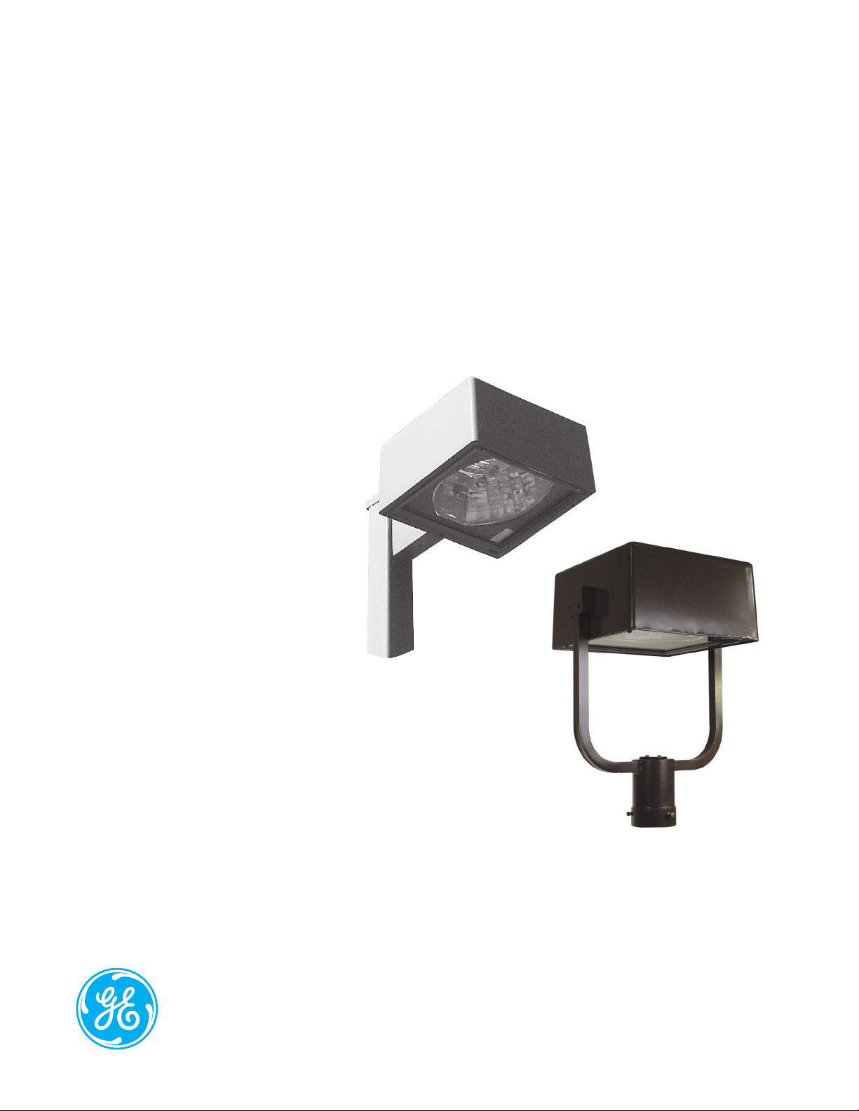
Decashield™ 175 (SPMM & SYMM)
imagination at work
Page 2

Product Features
Designed for superior photometric performance and architectural appeal, GE Outdoor Area Sightlighters provide
broad application flexibility. From parking lots to downtown areas, hospitals to shopping malls, business complexes
to residential neighborhoods, these fixtures will satisfy your large area lighting needs, while complementing your
aesthetic desires.
Applications
• Entranceways, walkways and parking areas
• Driveways, malls and cutoff wall lighting (with wall
mounting plate)
Housing
• Heavy-duty die-cast aluminum housing
Finish
• Polyester powder paint finish
Rating
• 1598 Listed Suitable for Wet Locations
/
Unique Features
• Cutoff optics
• Enclosed and gasketed
• Heat and impact resistant tempered flat glass lens
(standard)
• UV stabilized polycarbonate or acrylic prismatic drop
lens (optional)
• For cutoff wall lighting applications, order wall
mounting plate (WMPDB-SP) separately
• Shipped assembled with medium base – E26
standard – with lamp installed in socket
• Plug-in ignitor
• Unit shipped complete in one carton (Ballast secured
to housing)
• Magnapack packaging available
Page 3
Ordering Number Logic
Decashield™ 175 (SPMM & SYMM)
_ _ _ _ - _ _ - _ - _ - _ - _ - _ - _ _ _ - _ _ - _
PROD. ID
SPMM =
Square Pole
Mount
SYMM =
Pole Top
Yoke Mount
WATTAGE
05 = 50
07 = 70
10 = 100
15 = 150 (55V)
17 = 175
LIGHT
SOURCE
E = Energy Act
Compliant Pulse
MH (EPMH)
S = HPS
P = PMH
Standard:
Medium base
lamp installed in
socket
BALLAST
VOLTAGE COLOR
60Hz
0 = 120/208/240/
277 Multivolt
1 = 120
2 = 208
3 = 240
4 = 277
5 = 480
D = 347
F = 120X347
T = 220
50Hz
6 = 220
NOTE: Dual
voltage
connected
for lower voltage
TYPE
SELECTION
See Ballast and
Photometric
Selection Table
A = Autoreg
D = Bi-Level
G = Mag-Reg
with
Grounded
Socket
Shell
H = HPF
Reactor or
Lag
M = Mag-Reg
(Use only for
50, 70, 100, 150
watt HPS
480 volt)
PE
FUNCTION
1 = None
2 = PE Receptacle
NOTE: Receptacle
connected same
voltage as unit
except as noted.
Order PE Control
separately.
LENS
TYPE
A = Acrylic 2-in.
(51mm) Drop
Lens
G = Flat Tempered
Glass
L = Polycarbonate
2-in. (51mm)
Drop Lens
(Required for
Switched Quartz)
IES
DISTRIBUTION
TYPE
See Ballast and
Photometric
Selection Table
SC5 = Short Cutoff
Type V
MC3 = Medium Cutoff
Type III
AL = Aluminum
BL = Black
DB = Dark Bronze
GR = Gray
WH = White
Ballast and Photometric Selection Table
All light sources are clear unless otherwise indicated.
Ballast Type/Voltage
60Hz 50Hz
Light 120/208/ 347, Amb.
Wattage Source Multivolt 240/277/480 120X347 220 220 °C MC3 SC5** SC5** SC5**
SPMM
50 HPS H H H N/A N/A 25 178265 178307 178305 178306
70, 100, 150 (55V) HPS H G, H*, M H N/A H 25 178265 178307 178305 178306
70, 100 PMH H H C/F N/A N/A 25 178271 178665 178666 178667
150, 175 PMH N/A A,H H N/A N/A 25 178271 178665 N/A N/A
SYMM
50 HPS H H H N/A N/A 25 178526 178522 N/A N/A
70, 100, 150 (55V) HPS H G, H*, M H N/A H 25 178526 178522 N/A N/A
70, 100 PMH H H C/F N/A N/A 25 178527 178524 N/A N/A
150, 175 PMH N/A H H N/A N/A 25 178527 178524 N/A N/A
NOTE: N/A = Not available. C/F = Contact Manufacturer
*480 volt is A or M **Coated lamp standard for SC5 480V N/A for 150 PMH
IES Distribution Type
Photometric Curve Number 35-
Flat Glass 2-in. (51mm) Drop
Acrylic Polycarb.
IES Distribution Type
OPTIONS
B = Time Delay
Switched
(Drop
Lens only)
F = Fusing (Not
available
with multivolt or
dual voltage)
Page 4
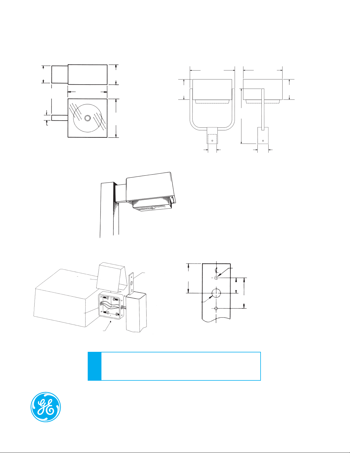
Product Dimensions
6.500 in.
(165 mm)
6.000 in.
(152 mm)
2.000 in.
(51 mm)
BOTTOM VIEW
* WITH DROP LENS ADD 2.000 in. (51mm)
SPMM
SIDE VIEW
7.500 in.*
(191 mm)
14.500 in.*
(368 mm)
14.500 in.*
(368 mm)
SPMM
with 2-in. (51mm) drop lens
SYMM
For mounting on 3.000 in. (76mm) pole tenon
16.750 in.
(424 mm)
7.500 in.
(191 mm)
20.500 in.
(520 mm)
3” Max OD Pole
Top Tennon
14.500 in.
(368 mm)
9.800 in.
(249 mm)
4.000 in.
(102 mm)
Installation
(Housing access not required)
Cover
Mounting
Bracket
GE Lighting Solutions • 1-888-MY-GE-LED • www.gelightingsolutions.com
1 - 8 8 8 - 6 9 - 4 3 - 5 3 3
GE Lighting Solutions, LLC is a subsidiary of the General Electric Company. The GE brand and logo are trademarks of the General Electric Company.
© 2012 GE Lighting Solutions, LLC. Information provided is subject to change without notice. All values are design or typical values when measured under laboratory conditions.
Cover
Screw
Nut
Plate
5.000 in.
(127mm)
1.250 in. DIA
(32 mm DIA)
FOR SQUARE and ROUND POLES
• Approximate Net Weight: 20 lbs (9 kgs)
• Effective Projected Area: 1.0 sq. ft. max. (0.09 sq. M max.)
• Suggested Mounting Height: 12-20 ft. (4-6 M)
DATA
DRILLING TEMPLATE
.438 in. DIA
(11 mm DIA)
2.266 in.
(58 mm)
4.532 in.
(115mm)
1. Pull power supply cable through nut plate
hole and secure with strain relief assembly.
2. Attach mounting bracket to pole and nut
plate.
3. Attach mounting bracket to luminaire
housing. Pull luminaire leads into pole
through wire access holes and connect
leads according to wiring instructions.
Install pole cap.
4. Install cover and secure with cover screw.
OLP-2941 (Rev. 06/19/12)
 Loading...