

GE Smart Water PNRV18ZWH01, Smart Water PNRV18ZBB01, Smart Water PNRV18ZWW01, Smart Water PNRV18ZBL01 Installation Instructions Manual
Page 1
GE SmartWater
™
Profile Performance Reverse Osmosis Filtration System
INSTALLATION INSTRUCTIONS
PNRV18ZBB01, PNRV18ZBL01, PNRV18ZWW01, PNRV18ZWH01
TABLE OF CONTENTS: Page #
Important Installation Recommendations 1
Product Specifications 2
Tools and Materials Required for Installation 2
Things to Check Before Installation 3
Step-by-Step Installation Instructions
— Feed water supply 4
—Drain connection installation 5
—Electronic faucet installation 6
—Tubing and electronics connection 7
— Reverse Osmosis assembly and storage tank installation 8
Sanitizing the Reverse Osmosis System 8
Installation Checklist 9
What the Reverse Osmosis System Does 9
Parts List 10, 11
IMPORTANT INSTALLATION RECOMMENDATIONS
Read entire manual. Failure to follow all guides and rules could cause personal injury or property damage.
• BE SURE TO FOLLOW ALL APPLICABLE STATE AND LOCAL CODES.
• Use a qualified installer.
• Do not install the Reverse Osmosis system outside or in extreme hot or cold temperatures. DO NOT INSTALL ON HOT WATER.
• Recommended installation is under the sink. However, the unit can be installed in a remote location, up to 30 feet away from the sink.
Additional installation materials may be required.
• If unit is installed in basement, with faucet on 1st floor, some capacity loss may be experienced. RVTNK1 can be purchased to provide
additional capacity.
• If Reverse Osmosis system is connected to a refrigerator icemaker, a special icemaker connection kit is required (RVKIT). Do not use
copper tubing for the connection between the Reverse Osmosis system and the refrigerator.
• Be sure the water supply conforms to the specifications on page 2. If water supply conditions are unknown, contact your municipal
water company or your local health department for a list of contaminants in your area and a list of laboratories certified by your state
to analyze drinking water.
WARNING: Do not use with water that is microbiologically unsafe or of unknown quality without adequate disinfection before
or after the system. Systems certified for cyst reduction may be used on disinfected water that may contain filterable cysts. This
Reverse Osmosis system contains a replaceable treatment membrane cartridge critical for effective reduction of Total Dissolved
Solids. The water should be tested periodically to verify that the system is performing satisfactorily. This system is acceptable for
treatment of influent concentrations of no more than 27 mg/L nitrate and 3 mg/L nitrite in combination measured as N and is
certified for nitrate/nitrite reduction only for water supplies with a pressure of 280kPa (40 psig) or greater. Small parts remaining
after the installation could be a choke hazard. Discard safely.
7178993 (7-00 JR) 215C1001P005-6 For Use and Care questions call: GE Answer Center® 800.626.2000
Pub. No. 49-5807-6 GENERAL ELECTRIC COMPANY, Appliance Park, Louisville, KY 40225
1
The GE RO PNRV18Z Model
Series is
Tested and Certified
to ANSI/NSF
Standard 58 for
TDS and Cyst reduction.
Page 2

MODEL PNRV18Z PRODUCT SPECIFICATIONS
Feed water pressure limits—pounds per square inch (psi) 40–125
c
Feed water temperature limits—minimum/maximum degrees F 40–100
Maximum Total Dissolved Solids (TDS)—parts per million (ppm) 2000
Maximum water hardness @ 6.9 pH—grains per gallon (gpg) 10
Maximum iron, manganese, hydrogen sulfide (ppm) <0.1
Chlorine in water supply allowable
b
Feed water pH limits (pH) 4–10
Product (quality) water, 24 hours—gallons 18.0
a
Process water per gallon of product water, 24 hours—gallons 4
a
Percent rejection of TDS (new membrane) 92
a
Cyst reduction 99.95%
Storage tank capacity—gallons 1.9
Automatic shutoff control yes
Prefilter and postfilter (# FX18P) Carbon block and granular activated carbon
Reverse Osmosis membrane (# FX18M) Thin film polyamid
Dimensions (inches) Height Width Depth
21 8 10
a. As tested by Water Quality Association standard “S-300.” Output according to ANSI/NSF Standard 58 is 10.9 gallons per day for the
Reverse Osmosis 18 model. Feed water at 50 psig and 77 °F with 750 parts per million sodium chloride. Quality water production,
amount of waste water and percent rejection all vary with changes in pressure, temperature, and Total Dissolved Solids.
b. Removed (maximum of 2.0 ppm) by the Reverse Osmosis prefilter. REGULAR MAINTENANCE IS REQUIRED. Chlorine will
destroy the Reverse Osmosis membrane.
c. If house water pressure is over 125 psi, install a pressure reducing valve in the water supply line.
If house water pressure is under 40 psi, install a Reverse Osmosis booster pump (contact your local plumbing supply company).
TOOLS AND MATERIALS REQUIRED FOR INSTALLATION
• Cordless Drill
• 1⁄4″Drill Bit
• 1-1⁄4″Carbide Hole Saw (if needed—see page 6)
• Adjustable Open-End Wrenches
• Phillips and Straight Screw Drivers
• Utility Knife
• Teflon Tape
TM
• Contents Included with the Product:
— Reverse Osmosis Assembly
— Product Literature (Installation Instructions, Owner’s Manual, Performance Data Sheet, and Owner Registration Card)
— Faucet Base Parts Bag
— Battery and Holder Parts Bag
— Water Supply Valve Parts Bag
— Drain Line Adapter
—27″Length of 3 ⁄8 ″Tubing
INSTALLER RESPONSIBILITY: The water supply valve (page 4) is included for use in areas where codes permit. Installer must comply
with state and/or local codes. If not, the installer must provide fittings to tap the cold water pipe for a feed water source to the Reverse
Osmosis system (must adapt to 1/4″OD tubing).
2
Page 3
THINGS TO CHECK BEFORE BEGINNING INSTALLATION
FEED WATER—The water supply to the undercounter Reverse Osmosis system must
have the qualities listed in the specifications (see page 2). Municipal water supplies most
often will have these qualities. Well water may need conditioning—have the water tested
by a water analysis laboratory and get their recommendations for treatment.
CAUTION: For water with hardness greater than 10 grains (at 6.9 pH), the use
of
a softener is recommended. Failure to install a softener will reduce the life of
the Reverse
Osmosis membrane. See Fig. 1A for additional information on the
possible need for a softener.
DRAIN POINT*—A suitable drain point and air gap (check your local codes) are
needed for reject water from the Reverse Osmosis membrane cartridge.
RO FAUCET—The RO product water faucet installs on the sink or on the countertop
next to the sink. Often, it is installed in an existing sink spray attachment hole. Space is
required underneath for tubing to and from the faucet, and for securing the faucet in
place. All faucet connections and installation procedures are done on or above the sink
or countertop. Refer to
Electronic Faucet Installation
section.
BASEMENT INSTALLATION—If installing in a basement, leave enough tubing in
place during installation to be able to move unit to floor for ease of servicing and making
filter/membrane changes.
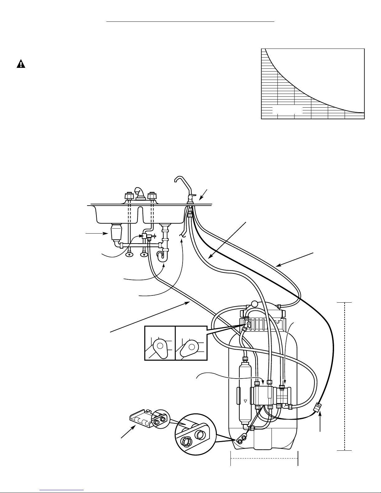
INSTALLATION OVERVIEW
RO product
water faucet
1/4″tubing, marked
WATER SUPPLY
Air gap device
inside faucet
Battery pack
Water supply valve
or compression fitting
Sink
p-trap
Drain
line*
Disposer
Leadwires
Automatic
shutoff
assembly
1/4″tubing,
marked
1/4″BARB
into air gap
device
3/8″tubing, marked FAUCET
Electronics
box
21″
OPEN
CLOSED
Tank shutoff valve
Flow
*For Drain line options refer to
Drain Connection Installation
section.
10″
overall width
including filter system
3
Fig. 1B.
Fig. 1A.
8
7.5
7
6.5
Incoming Water pH
6
WATER SOFTENER RECOMMENDED
Water Softener
not required
30
2010
INCOMING WATER HARDNESS (GPG)
50
40
60
FLOW
Page 4
STEP-BY-STEP INSTALLATION INSTRUCTIONS
FEED WATER SUPPLY
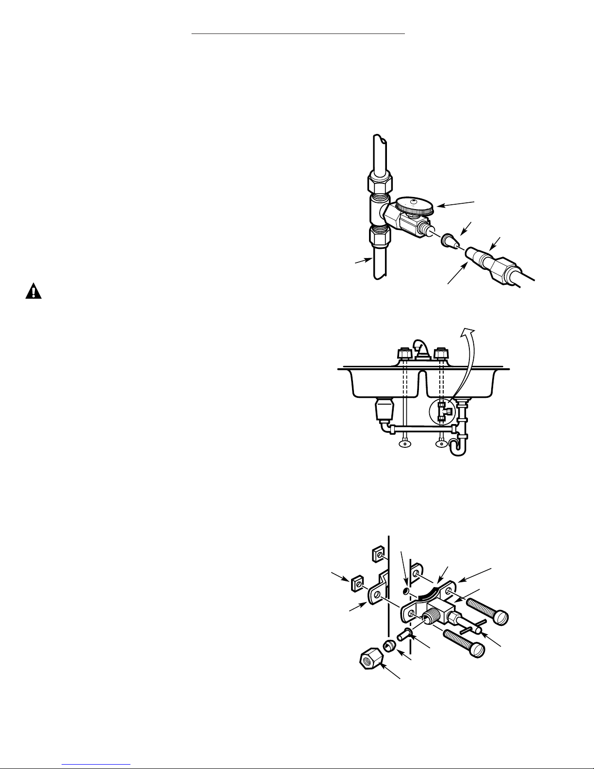
Check and comply with local plumbing codes as you plan, then install a cold feed water supply fitting. For new home installation using
standard plumbing fittings, see Fig. 2A below. A typical installation for existing homes using the saddle valve is shown in Fig. 2B below.
A. PREFERRED INSTALLATION
1. Turn off the cold water supply.
2. Complying with plumbing codes, install a fitting on the cold
water pipe to adapt 1 ⁄4 ″OD tubing. A typical connection is
shown in Fig. 2A (parts not included). Make sure a water
supply valve is used.
B. OPTIONAL INSTALLATION
Where codes permit
NOTE: Codes in the state of Massachusetts require installation
by a licensed plumber and do not permit the use of the saddle
valve. For installation, use plumbing code 248-CMR of the
Commonwealth of Massachusetts.
1. Turn off the cold water supply and attach saddle valve as
shown in Fig. 2B.
DANGER: To protect yourself from serious injury or
fatal shock, use a battery powered hand drill only to make
the hole. Do not use an electric drill.
2. Close the water supply valve by turning the handle clockwise.
3. Open the main water supply valve and several house faucets
to purge air from the system. Close faucets when water runs
smoothly.
4
Fig. 2A.
PREFERRED WATER SUPPLY CONNECTION
(using compression fitting)
TYPICAL
LOCATION
OPTIONAL WATER SUPPLY CONNECTION
(using saddle valve)
Pre-drill
1⁄4″ hole
Seal—make sure
the seal is in place
Clamp X
Nut (2)—not
required if
holes in
clamp are
threaded
Valve
Handle
Nut
Cold
water
1⁄4″compression fitting
Insert
Cold
water
pipe
1⁄4″ tubing to Reverse Osmosis
inlet, step 2, on page 7.
Ferrule
Ferrule
Insert
Use to connect
the tubing,
step 2, on page 7.
❵
Clamp Z
Fig. 2B.
Water supply valve
Page 5

5
FILTRATION DRAIN CONNECTION INSTALLATIONS
Check and comply with all state and local plumbing codes as you plan.
CAUTION: The options detailed below are the ONLY approved installation
configurations. Do not use any drain saddle device.
NOTE: Failure to follow these Installation Instructions will void the Warranty, and the
Installer will be responsible for any service, repair, or damages caused thereby.
PREFERRED INSTALLATION OPTIONS
(Options A, B and C)
OPTION A.
BASEMENT ACCESS INSTALLATION (FIG. 3A)
Route the drain line DIRECTLY from the Reverse Osmosis system to a standpipe in
the basement, bypassing the air gap provided in the faucet. The drain line may also
be routed in the basement to a floor drain or washtub, provided that the air gap in the
basement is maintained. Avoid dips, loops or low spots in the drain line. The basement
air gap and drain installation configuration must conform to all local codes. Special air
gap fittings are available to connect the drain line to the top of the standpipe.
OPTION B.
SEPARATE VENT INSTALLATION—2 P-TRAP (DRY-VENTED) (FIG. 3B)
Install a separate dry-vented p-trap under the sink to be used exclusively for the Reverse
Osmosis drain line. A dry-vented p-trap is a p-trap that has its own vent/stack. Attach
the provided drain line adapter to the p-trap and secure it with the slip joint nut and
washer as shown. Route the drain line from the air gap to the drain line adapter
ensuring that there are no dips, loops or low spots in the line, which could result in a
clogged drain line. The drain line adapter should be aligned vertically such that the
hose connection points in a direction 45° of vertical. (See Fig. 3E.) The drain line
MUST be routed through the air gap provided in the RO water faucet.
OPTION C.
SHARED VENT INSTALLATION— 2 P-TRAP (WET-VENTED) (FIG. 3C)
Install a p-trap under the sink to be used exclusively for the Reverse Osmosis drain line.
A wet-vented p-trap is a p-trap that shares a common vent/stack. Attach the provided
drain line adapter to the p-trap and secure it with the slip joint nut and washer as
shown. Route the drain line from the air gap to the drain line adapter ensuring that
there are no dips, loops or low spots in the line, which could result in a clogged drain
line. The drain line adapter should be aligned vertically such that the hose connection
points in a direction 45° of vertical. (See Fig. 3E.) The drain line MUST be routed
through the air gap provided in the RO water faucet. Locate the p-trap as high as
possible (minimum of 4″above horizontal pipe from second sink or disposer).
SECONDARY RECOMMENDATION
(Use only if option A, B or C is not possible.)
OPTION D.
DRAIN LINE ADAPTER INSTALLATION (FIG. 3D)
DO NOT install the drain line DOWNSTREAM OF A DISPOSAL or in a
HORIZONTAL PIPE. Install the provided drain line adapter under the sink as
shown. The baffle-tee or y-connector shown MUST be in place (purchase and install
if necessary) to prevent a clog in the Reverse Osmosis drain line. Route the drain line
from the air gap to the drain line adapter ensuring that there are no dips, loops or low
spots in the line, which could result in a clogged drain line. The drain line adapter
should be aligned vertically so that the hose connection points in a direction 45° off
vertical. (See Fig. 3E.) This installation MAY result in a slight drain noise in the sink
drain when the Reverse Osmosis system is operating. Rotate the Drain Line adapter tee
assembly slowly until noise is minimized. Generally, 180° opposite the existing
horizontal pipe/baffle-tee is a good orientation.
Fig. 3A.
Fig. 3B.
Fig. 3C.
Fig. 3D.
Fig. 3E.
From second sink
or disposer
From second sink or
disposer
From second
sink or disposer
Mandatory baffle-tee
or y-connector
From second
sink or disposer
45°
From
faucet air
gap
Drain line from
Reverse Osmosis
by-passing faucet
air gap
Maintain air gap at
drain point in
basement
From faucet air gap
Drain line
adapter
Drain line adapter
Separate p-trap
Cap (not
included)
Cap (not
included)
4″
Min.
Drain line connection should
be 180° opposite existing
horizontal pipe/baffle-tee as
shown in diagram
From faucet air gap
Drain line adapter
Drain line adapter
Proper drain line adapter orientation.
Page 6

ELECTRONIC FAUCET INSTALLATION
Be sure there is room underneath the sink to make the needed
connections. Select one of the following places to install the faucet:
—IN an existing sink spray attachment or soap dispenser hole
—IN a hole to be drilled in the sink top
—IN a hole to be drilled in the countertop, next to the sink
NOTE: Looking at Fig. 4D, be sure the faucet base will fit flat against the
surface at the selected location so the gasket will seal. The base may
have to be angled sideways or diagonally.
1. If drilling is needed, make a 1-1 ⁄ 4″dia. hole. Be sure to use the
proper procedure for drilling porcelain or stainless steel.
2. Looking at Fig. 4A, insert a screw into the NON-SLOTTED base
mounting hole. Turn a flat nut a few turns onto the screw.
3. Position the base gasket over the mounting hole. Set the base on
the gasket, routing the leadwire through the mounting hole.
Holding the flat nut under the sink with one finger, tighten the
screw until just snug.
4. Turn the remaining flat nut a few turns onto the other screw.
Position the screw in the slotted base mounting hole and tighten
until snug. Make sure the gasket position is properly aligned and
carefully tighten both screws until the base is held firmly in place.
Do not overtighten and break the base.
5. Assemble the top faucet base and hex nut onto the faucet stud
(Fig. 4C). Tighten the nut until snug.
6. Insert washer into tubing adapter. Securely tighten to faucet stud.
7. Take the 27″ length of 3 ⁄ 8″tubing and push one end completely
onto the 3 ⁄8 ″faucet barb fitting (Fig. 4D).
8. Position the Reverse Osmosis system under the sink. Referring to
Fig. 5, page 7, hang the system on cabinet wall.
9. Route the 1 ⁄ 4″tubing (marked “1 ⁄4 ″BARB ON FAUCET”) and
the 3 ⁄8 ″tubing (marked “FAUCET”) up through the mounting
hole and faucet base:
a. Push one end of the 1 ⁄4 ″tubing onto the 1 ⁄4 ″barb on the
faucet.
b. Using the compression nut, fasten the 3 ⁄8 ″tubing to the tubing
adapter and tighten the nut. Make sure the tubing is completely
seated in the adapter.
10. Remove the short shipping tube and insert the spout into the
faucet body.
11. Lower the faucet assembly and lock into place on the faucet base.
6
Fig. 4C.
Fig. 4A.
Fig. 4B.
Fig. 4D.
Faucet
base
Nut (2)
Screw (2)
Washer
Hex nut
Top faucet base
Faucet
Lever
Spout
Faucet base
leadwire
1-1/4″ dia. mounting
hole in sink or
countertop
Gasket
Faucet
base
NOTE: For ease of service and
maintenance, keep tubing
lengths long enough so removal
of the Reverse Osmosis system
from under the sink is possible.
Faucet stud
Compression
nut
Tubing
adapter
3/8″barb
fitting
1/4″tubing marked
1/4″BARB
1/4″barb
fitting
3/8″tubing
marked FAUCET
3/8″tubing,
27″ long
Faucet base
Compression
nut
TOP VIEW
ASSEMBLED
Screw (2)
Nut (2)
From RO
To drain
From RO
Page 7

FLOW
FAUCET DRAIN TUBING, WATER SUPPLY TUBING, AND ELECTRONIC LEADWIRE CONNECTION
If Option A, BASEMENT ACCESS INSTALLATION, from page 5 was used, go to step 2.
1. If Option B, C or D from page 5 was used, connect the faucet
drain tubing by running the 27″ length, 3⁄ 8″tubing from the
3⁄8″faucet barb to the drain fitting (installed on page 5).
Keep this tubing run as short and straight as possible, without
loops, dips, or low-spots. Cut the tubing as needed and insert
into the drain fitting (Fig. 3B, 3C or 3D, page 5).
2. To connect the water supply tubing: Run the 1 ⁄4 ″tubing
(marked “WATER SUPPLY”) from the Reverse Osmosis inlet
to the feed water supply fitting (reference Fig. 2A or 2B, page
4). Connect the tubing as applies (Fig. 2A or 2B, page 4) and
tighten the nut securely (use Teflon Tape™ to prevent leaks).
3. To connect the electronics box:
a. Remove the box’s back cover and fasten the battery
connector to the battery pack (see Fig. 5). Be sure the
batteries are installed correctly. Place the battery pack in
the electronics box and reinstall the back cover.
b. Fasten the electronics box leadwire to the faucet base
leadwire (see Fig. 5). If needed, a 15′ leadwire extension
is available from GE (part #WS07X10009).
7
RO product
water faucet
Air gap device
inside faucet
1/4″tubing, marked
WATER SUPPLY
Battery pack
Water supply valve
or compression fitting
Sink
p-trap
Drain
line*
Disposer
Leadwires
Automatic
shutoff
assembly
1/4″tubing,
marked
1/4″BARB
into air gap
device
3/8″tubing, marked FAUCET
Electronics
box
OPEN
CLOSED
Tank shutoff valve
Flow
*For Drain line options refer to
Drain Connection Installation
section.
Fig. 5.
Page 8

SANITIZING THE REVERSE OSMOSIS SYSTEM
Sanitize upon installation of the Reverse Osmosis system and after servicing inner
parts of the Reverse Osmosis system, including replacement of prefilter, postfilter
and Reverse Osmosis cartridge. It is important to wash hands with anti-bacterial
soap before handling inner parts of the system.
CAUTION: If installing unit in New Construction, ensure house plumbing is flushed
thoroughly before opening the water supply valve. Also, before sanitizing, be sure to
remove all cartridges as follows. Chlorine will destroy the Reverse Osmosis cartridge.
1. Be sure the water supply valve to the Reverse Osmosis system is turned off and the
RO water faucet is open. Allow the system to drain completely (this takes several
minutes).
2. Place a dry towel under unit. Remove the clamp retainers and clamp
sections from top of unit.
3. Lift the Reverse Osmosis cap straight up (a slight resistance is normal) from
the Reverse Osmosis housing (no need to disconnect tubing) and move aside.
NOTE: If the cap o-ring seal remained in the Reverse Osmosis housing,
replace it on the cap.
4. Remove the Reverse Osmosis cartridge and outer prefilter cartridge from
the Reverse Osmosis housing and place in a clean plastic bag. Dispose of
water from the Reverse Osmosis housing.
5. Fill the Reverse Osmosis housing with fresh cold water, to about 1″ from the top.
Add one ounce (2 tablespoons) of ordinary 5.25% household chlorine bleach
and mix into the water. DO NOT ADD CHLORINE FIRST. Concentrated
chlorine may damage plastics.
6. Replace Reverse Osmosis cap, with the o-ring, and install the clamp retainers.
7. Close the red tank shutoff valve and disconnect postfilter at the tank shutoff valve.
Connect the Reverse Osmosis product water tubing (disconnect at electronics box)
directly to the tank shutoff valve, isolating the carbon postfilter as shown in Fig. 6B.
8
. Open the red tank shutoff valve and the water supply valve to the Reverse Osmosis system.
Allow system to fill for one minute. Now open the RO water faucet, locking the lever
upward against the spout.
9. Allow water to flow through the Reverse Osmosis system until all the bleach odor is
gone (approximately 20 minutes).
10. Turn off the water supply valve to the Reverse Osmosis system. Close the RO water
faucet AFTER the water flow stops.
11. Close the red tank shutoff valve. Disconnect the water product line from the red tank
shutoff valve and connect to the electronics box. Reconnect postfilter line to red tank
shutoff valve. Open red tank shutoff valve.
12. a. Repeat steps two and three. Be careful of water in the Reverse Osmosis housing.
Dispose of water.
b. Replace the Reverse Osmosis cartridge with the o-ring seal downward and the
prefilter cartridge with “this side up” facing upward. BE SURE HANDS HAVE
BEEN CLEANED WITH AN ANTI-BACTERIAL SOAP.
c. Repeat step 6.
8
CLOSED OPEN
Tank shutoff valve
Automatic shutoff assembly
Postfilter
Product water
tubing
Red tank
shutoff valve
Clamp sections
(2)
Reverse Osmosis
housing
Bottom
end
Flow
control
Cone screen
Reverse
Osmosis
cap
Green
protective
cap
Vacuum
relief valve
Postfilter
line
Prefilter
cartridge
Reverse Osmosis
cartridge
End with o-ring
seals downward
Clamp retainers
(2)
Fig. 6A.
Fig. 6B.
Connect Reverse
Osmosis water tubing
to tank shutoff valve
Disconnect
postfilter
Postfilter
Electronics
box
UP
FLOW
Page 9

PRESSURE TESTING THE SYSTEM
—DO THE SANITIZING PROCEDURE BEFORE PRESSURE
TESTING—INSTALLATION CHECKLIST
1. Open the water supply valve to the Reverse Osmosis system and
open the storage tank shutoff valve.
2. Check all connections for LEAKS.
3. In about 4 hours, pressure will build in the Reverse Osmosis
system. Carefully recheck all fittings and connections for water
leaks. Correct leaks if any are found.
4. Fill sink(s) 1/2 full of tap water and drain, checking drain
plumbing for leaks.
PURGING THE SYSTEM
1. Wait about 4 hours for the storage tank to fill.
2. Open the RO faucet until the tank is empty and flow stops.
3. Close the RO faucet and repeat these steps three more times.
The system is ready to make product water for use.
WARNING: Initially, the Reverse Osmosis cartridge
contains a food grade preservative that has to be purged
from the system before first use or whenever Reverse
Osmosis cartridge is replaced. The preservative will give
product water an unpleasant taste and odor.
INSTALLATION CHECKLIST
1. Are all tubing connections tightened? Do they run between the
points shown? No leaks!
2. Is the faucet base leadwire connected to the electronics box
leadwire?
3. Is the battery holder connected to the electronics box and are
the batteries installed in the holder correctly?
4. Did you use drain option B, C or D? Make sure the 3 ⁄8 ″drain
tubing, from the faucet to the drain point, is without loops,
dips, or low-spots.
5. Is the tank shutoff valve in the open position?
6. Is the water supply shutoff valve open?
7. Did you sanitize and purge the system?
WHAT THE REVERSE OSMOSIS SYSTEM DOES
Reverse Osmosis removes Total Dissolved Solids (TDS) and
organic matter from water by diffusing it through a special
membrane. The membrane separates minerals and impurities
from the water and they are flushed to the drain. High quality
product water goes directly to the drinking water faucet or to the
storage tank. The system makes a good supply of drinking water
each day (see
Product Specifications
). How much it makes depends
on the feed water supply pressure, temperature, and quality.
The system includes an electronic faucet assembly with an
integrated testing feature. When water is taken from the faucet,
a flashing green indicator light means TDS removal is within
specified limits and that water quality is good.
The prefilter and postfilter are replaceable cartridges. The carbon
prefilter removes chlorine while also filtering sediments. The
postfilter removes any other undesirable tastes and odors before
you use the water.
THE GE ELECTRONIC MONITOR SYSTEM
Indicator lights on the faucet base show Reverse Osmosis
performance when the faucet is open to dispense water.
Flashing Green Light—The Reverse Osmosis system is providing
high quality drinking water.
NOTE: If the Reverse Osmosis system is connected to the
refrigerator, this light will also flash when the icemaker or
dispenser is in use.
The green light may stop flashing when the supply of Reverse
Osmosis water is nearly gone and flow from the RO water faucet
decreases. This is a normal condition.
Flashing Amber “FILT” Light—The prefilter and postfilter cartridges
need replacing. This occurs after 6 months or 900 gallons of
product water use, whichever occurs first. Also, replace the 4 “AA”
alkaline batteries in the electronics box. Good batteries are needed
to ensure correct indicator light operation. Weak batteries may
give a false “RO” light indication. Changing the batteries resets the
6 month or 900 gallon period.
Flashing Amber “RO” Light—The Reverse Osmosis cartridge is no
longer removing at least 75% of the Total Dissolved Solids (TDS)
from the supply water. The Reverse Osmosis cartridge, flow
control, and screen need replacing.
NOTE: Disregard initial or short periods (a few seconds) of the
flashing “RO” light. Long periods of limited or no use can cause
the TDS levels to temporarily change.
9
Flashing amber
“RO” light
Flashing green
“OK” light
Flashing amber
FILTER light
Fig. 7.
Page 10

LITERATURE
10
NOTE: Codes in the state of Massachusetts require installation
by a licensed plumber and do not permit the use of the saddle
valve. For installation, use plumbing code 248-CMR of the
Commonwealth of Massachusetts.
58
999
1
3
4
55
5
41
6
7
8
13
12
9
10
11
35
34
33
14
32
40
39
38
56
43
44
TO
FAUCET
AIR GAP
45
46
31
BOTTOM
10
9
13
12
15
21
22
16
20
19
18
17
23
24
57
29
28
25
27
26
47, 48
49, 50
51
WS15X10014
SHUTOFF ASM.
Page 11

GENERAL ELECTRIC PARTS CATALOG
REF. NO. PART NO. PART DESCRIPTION BB01 BL01 WH01 WW01
0001 WS15X10011 FAUCET BLACK TIP & LEVER 111-
WS15X10013 FAUCET–ALL WHITE ---1
0003 WS10X10008 TOP FAUCET BASE BLACK 1 1 - -
WS10X10010 TOP FAUCET BASE WHITE - - 1 1
0004 WS02X10007 SCREW #6-32 X 1 -3/8″ 2222
0005 WS10X10011 BASE FAUCET BLACK 1 1 - -
WS10X10004 BASE FAUCET WHITE - - 1 1
0006 WS08X10003 GASKET FAUCET 1111
0007 WS02X10008 NUT 2222
0008 WS03X10003 ADAPTER TUBING 1111
0009 WS22X10005 NUT 1/4″ TUBE 8888
0010 WS22X10006 INSERT 1/4″ TUBE 7777
0011 WS15X10004 VALVE SHUTOFF TANK 1111
0012 WS22X10007 INSERT 3/8″ TUBE 5555
0013 WS22X10008 NUT 3/8″ TUBE 3333
0014 FX18L FILTER POST CARBON 1111
0015 WS28X10002 HOLDER FILTER 1111
0016 WS21X10001 BOX ELECTRONICS 1111
0017 WS03X10004 WASHER FLOW 1111
0018 WS01X10001 MAGNET 1111
0019 WS03X10005 SPRING 1111
0020 WS06X10002 HOLDER BATTERY 1111
0021 WS10X10005 VALVE BOTTOM 1111
0022 WS22X10009 DIAPHRAGM 2222
0023 WS22X10010 PLUNGER 1111
0024 WS22X10012 ELBOW 1/8″ NPT X 1/4″ 1111
WS22X10011 ELBOW 1/8″ NPT X 1/4″ 1111
0025 WS22X10013 CONNECTOR W/NUT 1/8 NPT 1111
WS22X10014 CONNECTOR 1/8″ NPT X 1/4 1111
0026 WS10X10006 VALVE TOP 1111
0027 WS10X10007 VALVE CENTER 1111
0028 WS02X10010 SCREW # 10-14 X 1-3/4″ 4444
0029 WS22X10015 CONNECTOR W/NUT 1/4 NPT 1111
WS22X10018 CONNECTOR 1/4 NPT X 1/4 1111
0030 WS20X10001 LINER ASSEMBLY 1111
0031 WS08X10004 O-RING 5/16″X 7/16″ 1111
0032 WS15X10007 VALVE VACUUM RELIEF 1 1 11
0033 WS20X10002 BLADDER 1111
0034 WS35X10004 CHECK KIT BALL 1111
0035 WS20X10003 HOUSING R.O. 1111
0038 WS03X10012 O-RING R.O. CAP 1 111
0039 WS31X10007 CAP R.O. 1 111
0040 WS22X10019 ELBOW 1/4″ NPT X 1/4″1111
0041 WS15X10008 WATER SUPPLY VALVE* 1111
0043 WS03X10015 SCREEN CONE 1111
0044 WS03X10016 CONTROL FLOW 1111
0045 FX18M R.O. CARTRIDGE 1 1 11
0046 FX18F PREFILTER–CARBON 1 1 11
0047 WS07X10005 TUBING 1/4″X 10 FT 1111
0048 WS07X10006 TUBING 1/4″ X 20 FT 1111
0049 WS07X10007 TUBING 3/8″ X 20 FT 1111
0050 WS07X10008 TUBING 3/8″ X 20 FT 1111
0051 WS15X10014 SHUTOFF ASSEMBLY 1111
0055 WS28X10003 RETAINER CLAMP 2222
0056 WS28X10004 CLAMP HOUSING 2222
0057 FLOW RESTRICTER
0058 DRAINLINE ADAPTER
0999 49-5803-3 PM MANUAL USE & CARE 1111
49-5807-3 PM INSTRUCT INSTAL 1111
PERFORMANCE DATA SHEET
PNRV18Z
NOTE: Codes in the state of Massachusetts require installation by a licensed plumber and
do not permit the use of the saddle valve. For installation, use plumbing code 248-CMR of
the Commonwealth of Massachusetts.
11
Page 12

GENERAL ELECTRIC COMPANY, Appliance Park, Louisville, KY 40225
 Loading...