

Page 1
1
GE SmartWater
™
INSTALLATION INSTRUCTIONS
GE Model GXITQ and GXITQR Filters
Part No. 215C1001P014 (8-99 JR) Pub. No. 49-50027-1
For Use and Care questions call: GE Answer Center® 800.626.2000
GENERAL ELECTRIC COMPANY, Appliance Park, Louisville, KY 40225
Do not use where water is microbiologically
unsafe or with water of unknown quality
without adequate disinfection before or
after the filter.
Small parts remaining after the installation
could be a choke hazard. Discard safely.
SPECIFICATIONS
INSTALLATION PRECAUTIONS
• Protect from freezing. Drain filter when room temperature drops below 32°F. (0°C.).
• Use the in-line water filtering system on a potable, safe-to-drink, home COLD water supply only. The filter
will not make unsafe water safe to drink. Do NOT use on HOT water (100°F. max.).
• Do not install on line pressure above 125 psi (862 kPa), or below 25 psi (172 kPa).
• All of the refrigerator installation requirements must be met when installing the filter.
• Do not use wicking or pipe dope sealer for fitting connections into head of filter. Teflon® tape is
recommended and included. Teflon is a registered trademark of DuPont.
• Do not install in direct sunlight.
• Installation must comply with existing state or local plumbing codes.
REQUIRED TOOLS FOR INSTALLATION
• a tube cutter
• 7/16″, 1/2″ and 9/16″ wrenches
• a knife
• a bucket or pan
CAUTION: Using pliers or vise grips WILL
damage the fittings.
OPTIONAL TOOLS FOR INSTALLATION
• a file
• sandpaper
Your new GE icemaker water filter comes complete with all the necessary hardware for installation.
Each filter gives you up to six months of great-tasting water.
Filter should be changed after 6 months of use.
Service Service Max.
Models Flow rate Life Pressure Temp.
GXITQ
0.5 gpm 2000 gal. or 6 months 25–125 psi 100° F.
GXITQR
(1.9 lpm) (7571 liters) (172–862 kPa) (38° C.)
If slow water or hollow ice occurs, replace filter.
System tested and certified by NSF
international against ANSI/NSF
Std. 42 for
the reduction of chlorine
(Class 1), and taste and odor.
WARNING
Page 2
2
INSTALLING THE FILTER
LIMITED 60 DAY WARRANTY
1. All of the refrigerator installation
requirements must be met when
installing the filter.
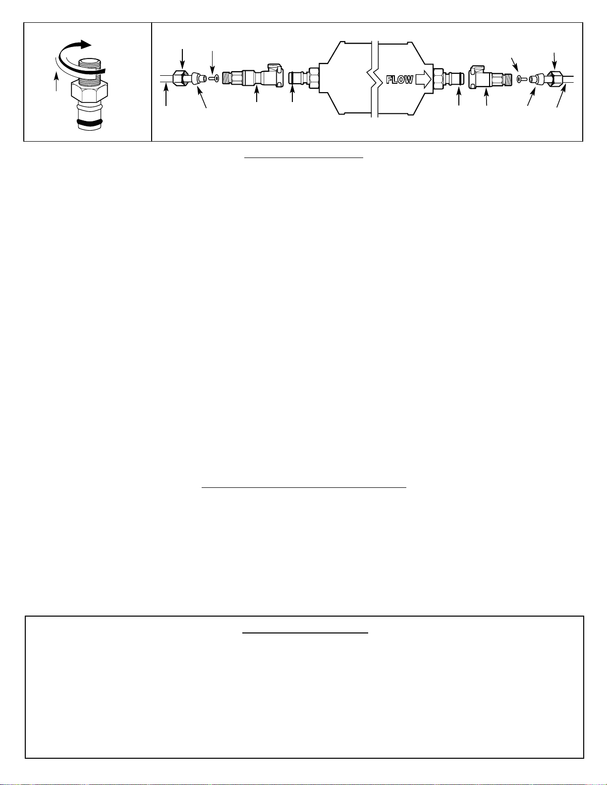
Attach Fittings to Filter
2. a. Remove yellow endcaps from filter.
b. Apply 1 to 2 wraps of the included
Teflon tape to threads of o-ring
fittings, as shown.
c. Thread o-ring fittings into both ends
of the filter body and tighten snug with
a wrench. Leave at least one turn of
thread showing.
Cut Tubing
3. Shut off water supply.
4. The filter is to be inserted (spliced) into
the 1/4″OD supply tube that feeds
water to the refrigerator. (Do not cut any
water lines internal to the refrigerator.)
Locate the filter as close as possible to
the supply water shut-off valve. If the
filter needs to be located behind the
refrigerator, there needs to be at least 6
inches of clearance. If the appliance
must be moved, make sure there is
proper protection on the floor.
5. Cut the tubing, making sure the ends
are square and no burrs protrude.
Deburr ends with file or sandpaper
if necessary.
Attach Fittings to Tubing
6. Slip brass
nuts then ferrules over both
tubing ends, leaving 1/4″of tubing
exposed from end. (See figure for
ferrule orientation). If your
tubing is
plastic, place brass inserts into ends
of tubing.
7. a. Insert end of supply side tubing
into the valved fitting (the
longer
fitting);
hand-tighten nut onto
threads of fitting.
CAUTION: Be careful not to cross thread
the nut and the fitting.
b. Using two wrenches, tighten nut at
least one full turn.
c. Valved fitting is now installed. Turn
water supply on and inspect for leaks.
d. Repeat a and b for non-valved fitting
on the appliance side.
Flush Filter
8. Place filter outlet over bucket; fine
particles of carbon may be present
—
flush
by connecting filter
inlet
to valved fitting.
Fine carbon particles will be removed
during the flushing. Disconnect inlet to
stop flushing after 2 to 3 gallons of water
are flushed (approx. 5 minutes).
Final Connection and Leak Check
9. Connect the
outlet
of the filter to the
water line going to your refrigerator.
10.
Connect the inlet of the filter to the water
supply line and inspect for leaks. If a leak
occurs, tighten nuts or fittings until the
leak stops.
11. Write the date on the filter and also
mark your calendar to replace with
another filter after six months.
PROCEDURE FOR REPLACING THE FILTER
1. Get a bucket and a towel.
2. Disconnect the old filter at its
inlet
first
and then its outlet. Water source will shut
off automatically, but some water may
spill or drip back through the filter.
3. Attach fittings to both ends of the new
filter body.
a. Find fittings that mate with filter body.
b. Apply one to two wraps of Teflon tape
to threads of o-ring fittings, as shown.
c. Thread o-ring fittings into filter body
and tighten snugly.
4. Place filter outlet over bucket; fine
particles of carbon may be present
—
flush
by connecting filter
inlet
to valved fitting.
Fine carbon particles will be removed
during the flushing. Disconnect inlet to
stop flushing after 2 to 3 gallons of water
are flushed (approx. 5 minutes).
5. Connect the filter
outlet
first, then
reconnect the inlet.
6. Write the date on the filter and also mark
your calendar to replace with another
filter after six months.
• What does this warranty cover?
— Any defect in materials or workmanship in the
manufactured product.
• What does this warranty not cover?
— Customer installation. The Installation Instructions cover installation
and replacement instructions.
— Defects that result from abuse, misuse, alterations, improper installation
or damage not caused by GE.
— Liability on the part of GE under this or any other warranty for any
indirect or consequential damage.
— Products that are used for commercial or industrial applications.
• For how long after the original purchase?
— Sixty (60) days.
• How do I make a warranty claim?
— Return to the retailer from which it was purchased along with a copy of
the “Proof of Purchase.”
• How does state law relate to this warranty?
— This warranty gives you specific legal rights, and you may also have other
rights which vary from state to state.
Teflon
tape
Brass nut
Brass nut
Brass insert (for plastic tubing)
Brass insert (for
plastic tubing)
Water line
tubing
Water line
tubing
Ferrule
Ferrule
Valved fitting
Non-valved
fitting
O-ring
fitting
O-ring
fitting
SUPPLY SIDE INLET
OUTLET
APPLIANCE SIDE
Follow Directions for Proper Assembly
Page 3

Sistema probado y certificado por
NSF internacional contra norma
42 de ANSI/NSF para la reducción
de cloro (Clase 1), y sabor y olor.
No debe usarse en aquellos lugares en los
que el agua no es microbiológicamente
segura, o si se desconoce la calidad del agua.
Cerciórese de que el agua se desinfecta
adecuadamente, ya sea a la entrada o a la
salida del filtro.
Las pequeñas piezas que sobran después de
la instalación pueden constituir un riesgo de
asfixia. Deséchelas adecuadamente.
1
GE SmartWater
™
INSTRUCCIONES PARA LA INSTALACION
Filtros GE modelo GXITQ y GXITQR
Si tiene preguntas acerca del uso y cuidados llame a: Centro de atención GE Answer Center®, tel. 800.626.2000.
GENERAL ELECTRIC COMPANY, Appliance Park, Louisville, KY 40225
ESPECIFICACIONES
CUIDADOS DURANTE LA INSTALACIÓN
• Evite la congelación. Cuando la temperatura de la habitación baja de los 32°F (0°C), desagüe el filtro.
• Solamente utilice el sistema de filtrado en línea cuando el agua residencial suministrada es FRÍA, potable y puede consumirse con
seguridad. El filtro no purifica el agua ni la hará potable. NO se utilice con agua CALIENTE. (100° F, 38°C max.).
• No lo instale en líneas de agua cuya presión sobrepase las 125 psi (862 kPa), o esté por debajo de las 25 psi (172 kPa).
• Es necesario cumplir con todos los requisitos de instalación del refrigerador al instalar el filtro.
• No utilice mecha de soldadura o sellador de tuberías para ajustar la conexión de los accesorios en el cabezal del filtro. Para el efecto,
se incluye y se recomienda la cinta Teflon®. Teflon es una marca registrada de DuPont.
• No lo instale en un sitio expuesto a la luz solar directa.
• La instalación debe cumplir con los códigos locales y estatales existentes.
HERRAMIENTAS NECESARIAS PARA LA INSTALACION
• un corta-tubos
• llaves de tuercas de 1/2″, 7/16″, y 9/16″
• un cuchillo
• una cubeta o una bandeja cacerola
PRECAUCION: El usar alicates o agarradores de
tornillos dañará los acopladores
HERRAMIENTAS OPCIONALES PARA LA INSTALACION
• una lima
• papel de lija
Su nuevo filtro de agua GE para fábrica de hielo se surte completo e incluye todos los accesorios necesarios
para la instalación. Cada filtro le brindará agua de excelente sabor hasta por seis meses. El filtro deberá cambiarse
después de 6 meses de uso.
Tasa Vida Temp.
Modelos de flujo media Presión máxima
GXITQ
0.5 gpm 2000 gal. ó 6 meses 25–125 psi 100° F.
GXITQR
(1.9 lpm) (7571 litros) (172–862 kPa) (38° C.)
Reemplace el filtro si el flujo de agua es lento o el hielo aparece hueco.
ADVERTENCIA
Page 4

COMO INSTALAR EL FILTRO
GARANTÍA LIMITADA POR 60 DÍAS
1. Es necesario cumplir con todos los requisitos de instalación del
refrigerador al instalar el filtro.
Cómo pegar los acopladores al filtro
2. a. Quite las tapas extremas amarillas de los extremos del filtro.
b. Aplique a la rosca de los acopladores anulares en O, una o
dos vueltas de la cinta Teflon provista.
c. Enrosque los acopladores de latón en ambos extremos del
cuerpo del filtro y apriételos bien con una llave de tuercas.
Deje que se vea por lo menos una vuelta de hilo.
Cómo cortar la tubería
3. Cierre el suministro de agua.
4. El filtro debe colocarse (empalmarse) en la línea de suministro
de agua de 1/4″ OD (diámetro externo) hacia el refrigerador.
(No corte ninguna línea de agua en el interior del refrigerador.)
Ubique el filtro loa más cerca posible de la válvula de cierre del
agua. Si el filtro debe instalarse detrás del refrigerador, deberá
haber un espacio libre mínimo de 6 pulgadas (15 cm). Cerciórese
de que dispone de una protección del piso adecuada si necesita
mover el aparato electrodoméstico.
5. Corte la tubería y cerciórese que los extremos están planos y que no
sobresale ninguna rebaba. Si es necesario, desbarbe bien los extremos
con una lima o papel de lija.
Cómo pegar los acopladores a las tuberías
6. Deslice las tuercas de latón y luego los casquillos anulares sobre ambos
extremos de la tubería, dejando 1/4″de tubería expuesta en cada
extremo. (Vea la figura para la orientación de la férula). Coloque las
inserciones de latón en los extremos de la tubería, si ésta es de plástico.
7. a. Inserte el extremo de la tubería del lado del suministro en el
aclopador con válvula (el acoplador
más largo
); apriete a mano
la tuerca en la rosca del acoplador.
PRECAUCION: Tenga cuidado de no cruzar el hilo de la tuerca con
el del acoplador.
b. Apriete la tuerca cuando menos una vuelta completa utilizando dos
llaves de tuercas.
c. Con esto quedó instalado el acoplador de válvula. Abra el
suministro de agua y compruebe que no haya fugas.
d. Repita el proceso de a y b para el acoplador sin válvula del lado del
aparato electrodoméstico.
Enjuague el filtro
8. Coloque la salida del filtro en una cubeta; pequeñas partículas de
carbón pudieran estar presentes—
enjuague
conectando la
salida
del
filtro al acoplador con válvula. Las pequeñas partículas de carbón se
eliminarán durante este proceso. Desconecte la entrada para parar el
paso del agua después de usar 2 o 3 galones (aprox. 5 minutos).
Conexión final y revisión de goteras
9. Conecte la
salida
del filtro a la tubería que conduce el agua hacia su
refrigerador.
10. Conecte la entrada del filtro a la línea de suministro de agua y
compruebe que no haya fugas. Si se presentara alguna fuga, apriete las
tuercas o los acopladores hasta que cesen las fugas.
11.Escriba la fecha en el filtro y también anótela en su calendario para
recordar que debe reemplazar el filtro después de seis meses.
PROCEDIMIENTO PARA REEMPLAZAR EL FILTRO
1. Consiga una cubeta y una toalla.
2. Desconecte el filtro viejo, empezando por el
extremo de
entrada
y después el de salida. La
fuente de suministro de agua se cerrará
automáticamente, aunque algo de agua
pudiera regarse o gotear a través del filtro.
3. Fije los acopladores a ambos extremos del
cuerpo del filtro nuevo.
a. Encuentre los acopladores que se ajusten
al cuerpo del filtro.
b. Aplique a la rosca de los acopladores
anulares en O, una o dos vueltas de la
cinta Teflon, según se muestra.
c. Enrosque los acopladores anulares en O
en ambos extremos del cuerpo del filtro y
apriételos bien.
4. Coloque la salida del filtro en una cubeta;
pequeñas partículas de carbón pudieran estar
presentes—
enjuague
conectando la
entrada
del filtro al acoplador con válvula.
Las pequeñas partículas de carbón se
eliminarán durante este proceso.
Desconecte la entrada para parar el paso del
agua después de usar 2 o 3 galones (aprox.
5 minutos).
5. Conecte primero el lado de la
salida
del filtro
y después reconecte la entrada.
6. Escriba la fecha en el filtro y también anótela
en su calendario para recordar que debe
reemplazar el filtro después de seis meses.
• ¿Qué ampara esta garantía?
— Cualquier defecto de fabricación o de materiales en el producto terminado.
• ¿Qué no ampara esta garantía?
— La instalación por el cliente. Las instrucciones de instalación ofrecen la
información para la instalación y el reemplazo de
la unidad.
— Defectos producidos por abuso, maltrato, modificaciones, instalación
deficiente o daños no causados por GE.
— La responsabilidad de parte de GE, bajo esta o cualquier otra garantía por
cualquier daño indirecto o consecuencial.
— Los productos utilizados para usos comerciales o industriales.
• ¿Por cuánto tiempo tiene vigencia la garantía después de la fecha de compra?
— Sesenta (60) días.
• ¿Cómo hago una reclamación sobre la garantía?
— Devuelva el producto al distribuidor donde lo compró, junto con una copia
de su factura.
• ¿Cómo se relacionan las leyes estatales a esta garantía?
— Esta garantía le otorga derechos legales específicos, y
usted puede tener también otros derechos que varían
de un estado a otro.
Cinta
Teflon
Tuerca de latón
Tuerca de latón
Inserciones de latón (para
tubería de plástico)
Inserciones de latón
(para tubería de plástico)
Tubería de
línea de agua
Tubería de
línea de agua
Casquillo
anular
Acoplador
con válvula
Acoplador
sin válvula
Acopladores
anulares en O
Acopladores
anulares en O
LADO DEL SUMINISTRO
LADO DEL APARATO
ENTRADA SALIDA
Para lograr un montaje adecuado siga estas instrucciones.
FLUJO
Casquillo
anular
2
 Loading...