

Page 1
Congratulations on your purchase of the GE SmartHome™ Wireless Camera System (WCS). The WCS is a
combined wireless camera and video monitor/ receiver, an ideal combination for monitoring the porch,
watching the yard, pool, pets or the baby. It is also suited to many small business applications.
FEATURES
• 2.4GHz wireless technology
• Plug ‘n’ play installation
• High resolution black and white video camera with motion detection
• Built-in microphone transmits sound from camera to monitor
• High quality audio and video components for long life
• Supports up to 3 cameras
• Durable weather resistant camera construction
• Manual or auto switching between cameras
• AC or battery operation (batteries not included)
• IR LEDs for night vision
• Photocell sensor to automatically turn on night
vision when needed
The wireless camera can also be operated with the GE Rechargeable Battery Pack GESECWBAT2
(sold separately) for complete portability and extended battery life.
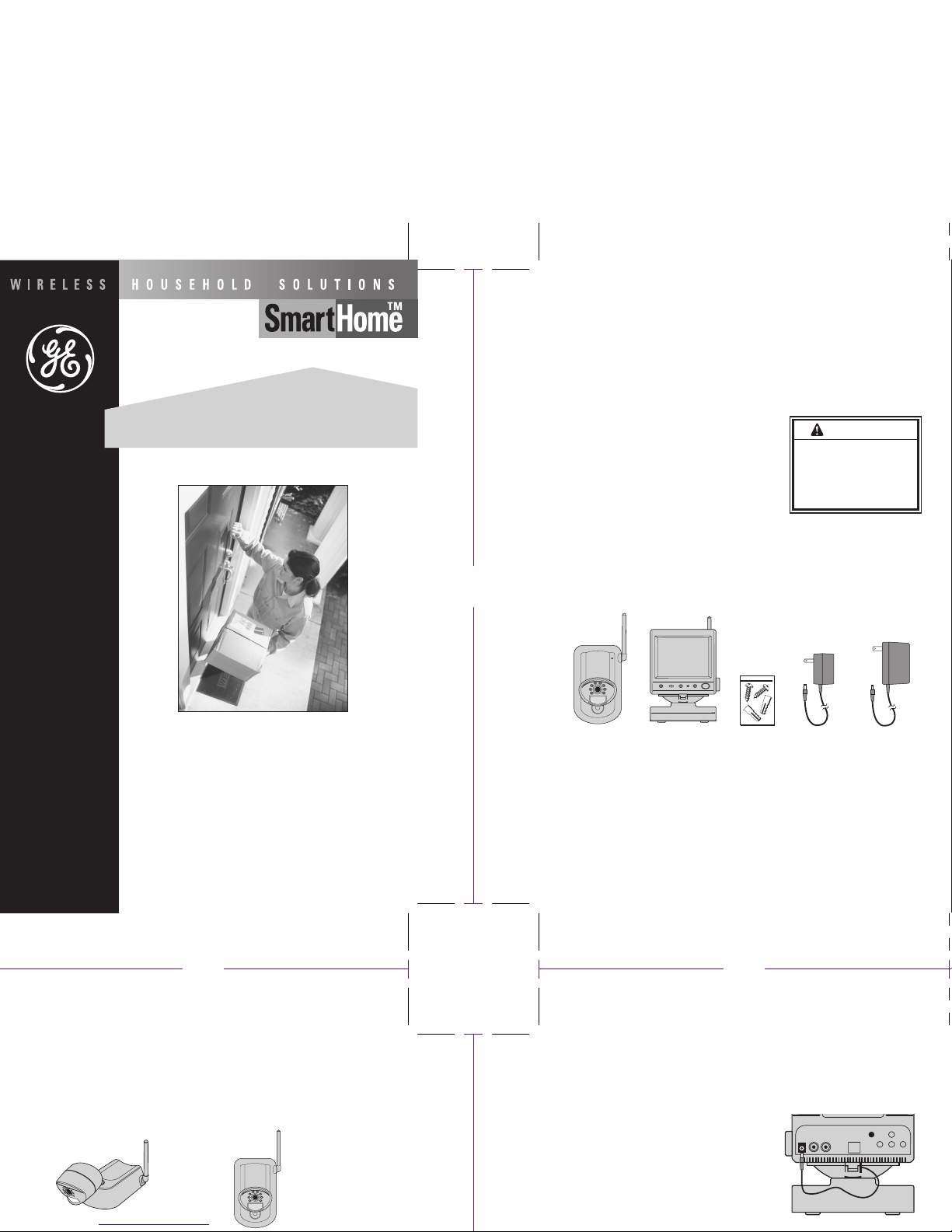
SYSTEM CONTENTS
Identify all parts before proceeding with installation.
THINGS TO CONSIDER BEFORE INSTALLATION
For best performance, follow these simple guidelines:
• Camera(s) should be installed between 8 and 13 feet above the area to be monitored
• The Camera should be aimed accordingly to optimize viewing area
• For best transmission, avoid installations where there are thick walls or major obstructions
between the Camera and Monitor
INSTALLING THE CAMERA (TRANSMITTER)
1.Unpack the Camera.
2. Decide whether the Camera will be wall-mounted or sit on a desk/table top. If wall mounting, use drilling
template on the back cover of these instructions. The Camera can be adjusted for either mounting
scenario by rotating the Camera head to the required position.
Mains Operation
1. Plug the monitor adapter into the power socket on the rear of the monitor.
2. Plug the power adapter in to a mains socket. Turn on the monitor by pressing the front push button.
Battery Operation
1. Find the pre-wired cable located in the base. Push
down the release tab under the rear of the unit,
remove the base from the unit.
2. Unwrap the cable and feed it through the slot next
to the release tab.
3. Remove the battery compartment lid on the underside
of the unit and install 10 X C type batteries (not included).
WARNING
Risk of fire
• When using an AC to DC adapter,
insure proper polarity and voltage.
Risk of electric shock
•For use in dry locations
USER'S GUIDE
Includes: Video/Audio Camera Transmitter & Monitor/Receiver
Questions? Call 1-800-GE LIGHT
Made in China for
GE Home Electric Products, Inc.
Nela Park, Cleveland, OH 44112
Desc.: GESECTVBW-2
WIRELESS CAMERA SYSTEM
INDOOR/OUTDOOR
1 6
Wireless Camera Monitor Mounting Screws 12V Camera Adapter 13.5 V Monitor Adapter
Wall MountedDesk/Tabletop
8.50"8.50"
Page 2

INSTALLING THE CAMERA (TRANSMITTER)
SCAN AUTO MANUAL
Volume
Power jack
DIP Switch
V-Hold
Brightness
Contrast
Beep Volume Control
VCA Jack
1.Unpack the Camera.
2.Decide whether the Camera will be wall-mounted or sit on a desk/table top. If wall mounting, use drilling
template on the back cover of these instructions. The Camera can be adjusted for either mounting
scenario by rotating the Camera head to the required position.
Wall MountedDesk/Tabletop
3.Decide whether to connect using AC power or batteries (not included). If using batteries remove battery
compartment lid on rear of Camera and install 5 x AA batteries. If using the 12V camera power adapter,
remove lid and connect power jack. Snap lid closed trapping
the cable in the slot behind the tab. Make sure the Camera is
positioned no more than 5 1/2 feet from an AC power outlet.
4. Select the Camera operating channel on the DIP switch in the battery compartment by moving switches
1,2, or 3 to the down position. Switch is present to channel 1.
The Camera (Transmitter) installation is now complete.
INSTALLING THE MONITOR (RECEIVER)
Audio
Out
Video
Out
DIP switch preset to
Channel 1 position
Trap cable in slot
and close lid
Page 3

Monitor (Receiver) Frequency Range 2.41 - 2.47 GHz
Current Consumption 800 mA
Channel Selection Electronic tuning with PLL
Output Audio/ Video 1V P-P / 200mV P-P
Signal/Noise Ratio 38db
Optional Battery Camera - 5 x AA (not supplied)
Monitor - 10 x C (not supplied)
General Operating temperature -10 °C to 40 °C
14 °F to 104°F
Humidity Less than 85%
This device complies with part 15 of the FCC rules. Operation is subject to the following two
conditions: (1) this device may not cause harmful interference, and (2) this device must
accept any interference received, including interference that may cause undesired operation.
Identify all parts before proceeding with installation.
THINGS TO CONSIDER BEFORE INSTALLATION
For best performance, follow these simple guidelines:
• Camera(s) should be installed between 8 and 13 feet above the area to be monitored
• The Camera should be aimed accordingly to optimize viewing area
• For best transmission, avoid installations where there are thick walls or major obstructions
between the Camera and Monitor
Mains Operation
1. Plug the monitor adapter into the power socket on the rear of the monitor.
2. Plug the power adapter in to a mains socket. Turn on the monitor by pressing the front push button.
Battery Operation
1. Find the pre-wired cable located in the base. Push
down the release tab under the rear of the unit,
remove the base from the unit.
2. Unwrap the cable and feed it through the slot next
to the release tab.
3. Remove the battery compartment lid on the underside
of the unit and install 10 X C type batteries (not included).
Replace lid cover.
4. Plug battery power lead into the socket on the rear of the Monitor/Receiver
OPTIMIZING THE WIRELESS CAMERA SYSTEM
The 2.4GHz video signals pass easily through your home’s interior walls, but the signal may be reflected
by power wires or plumbing inside the wall. Usually a slight adjustment of the Monitor and/or Camera
antenna will improve reception. Take care not to force the antennas past their lock positions. Sound level
can be adjusted using the volume control knob on the side of the Monitor. Adjust brightness/contrast as
required using controls on the rear of the Monitor. If needed the vertical hold can also be adjusted at the
rear. The most common source of interference are microwave ovens. Try to avoid mounting the Monitor
near a microwave oven or other source of RF interference such as cordless phones.
SWITCHING THE CAMERA ON/OFF
To preserve battery power, the camera can be switched
off while not in use. Simply turn the antenna position to
the OFF position as shown to the right. When the camera
is turned on, allow 60 seconds for the motion sensor and
night vision to warm up. During this period, the motion sensor
will be illuminated red.
MULTI-CAMERA OPERATION
The GE SmartHome™ Wireless Camera System
is designed to work with up to (3) Cameras. Additional Cameras
are sold separately (GESECWBWIN-2). IMPORTANT: When using more than one Camera, make sure each
Camera is assigned to a specific channel by adjusting the corresponding DIP switch down.
Accordingly the DIP switch located on the back of the Monitor should be adjusted to reflect the channel in use.
MOTION-SENSING CAMERAS
GE SmartHome™ Cameras are equipped with a motion sensor or PIR. When a Camera detects motion, a
red light flashes on the Camera and an audio alert sounds on the Monitor. The volume control for the alert
is on the rear of the Monitor.
OPERATING MODES
The system can be set to operate in one of three modes: SCAN, AUTO
or MANUAL. The desired operating mode can be selected using the
buttons on the front panel of the Monitor.
SCAN
Pressing the SCAN button places the system in Scan mode. The Monitor screen blanks into a standby
mode while the system continuously scans active cameras. If a camera detects motion, the monitor
displays the camera picture and the beeper will sound. Four minutes after the last detection, the screen
returns to standby mode and the Monitor resumes scanning. While in SCAN mode, the LED light on the
monitor is yellow. Pressing the MANUAL or AUTO button will cancel this mode.
AUTO
Pressing the AUTO button places the system in Auto mode. In this mode, the system automatically
rotates through all active cameras. When a camera detects motion, the monitor will display the picture
from the camera for a few seconds, and the beeper will sound. To avoid searching channels that do
not have cameras/transmitters assigned to them, set the dip switches (located on the back panel of
the monitor) for those corresponding channels to the OFF position. When in the AUTO Mode, the LED
light on the Monitor is solid green.
The dwell time (time taken to switch between cameras) is preset to 4 seconds and can be adjusted
between 2-30 seconds. To adjust the dwell time , press both the AUTO and MANUAL buttons simultaneously.
Each flash of the LED increases the dwell time by one second.
MANUAL
To select a specific Camera to monitor, press the MANUAL button. The monitor will switch to a different
camera each time the MANUAL button is pressed. To avoid searching channels that do not have cameras
assigned to them, set the dip switches (located on the back panel of the monitor) for those corresponding
channels to the OFF position. When in MANUAL mode, the LED light on the monitor is solid red.
SCAN AUTO MANUAL
1 6
Wireless Camera Monitor Mounting Screws 12V Camera Adapter 13.5 V Monitor Adapter
ON
OFF
Camera 1
In Use
Cameras
1 and 2
In Use
All Three
Cameras
In Use
Camera 1’s
DIP Switch
Camera 2’s
DIP Switch
(if using)
Camera 3’s
DIP Switch
(if using)
Page 4

SCAN AUTO MANUAL
Rear of VCR
Volume
Power jack
DIP Switch
V-Hold
Brightness
Contrast
Beep Volume Control
VCA Jack
5.50" 5.50" 5.50" 5.50"
NIGHT VISION
The camera includes IR LEDs, which allows viewing up to 5 feet in the dark when used with the adapter.
The IR LEDs are controlled by a photocell and are automatically turned on at low light level and off at high
light level. This helps to extend the battery life of the camera. NOTE: The range of the IR LEDs work best
with the AC adapter. The IR LED range is limited when used with alkaline batteries or the battery pack.
INSTALLING THE CAMERA (TRANSMITTER)
1.Unpack the Camera.
2.Decide whether the Camera will be wall-mounted or sit on a desk/table top. If wall mounting, use drilling
template on the back cover of these instructions. The Camera can be adjusted for either mounting
scenario by rotating the Camera head to the required position.
USING THE VIDEO MONITORING SYSTEM WITH A VCR
You can connect a VCR to the Video Monitoring System. This allows you to record the picture from your
Monitor. Connect the VCR’s Audio/Video input jacks (cable not supplied) to the Monitor’s Audio/Video
output jacks.
3.Decide whether to connect using AC power or batteries (not included). If using batteries remove battery
MONO
compartment lid on rear of Camera and install 5 x AA batteries. If using the 12V camera power adapter,
remove lid and connect power jack. Snap lid closed trapping
the cable in the slot behind the tab. Make sure the Camera is
positioned no more than 5 1/2 feet from an AC power outlet.
TROUBLE SHOOTING
If you are having trouble operating this product, please consult the guide below:
4. Select the Camera operating channel on the DIP switch in the battery compartment by moving switches
1,2, or 3 to the down position. Switch is present to channel 1.
SYMPTOM
No camera picture
Blank monitor
Interference on
camera picture
Audio problems
REMEDIES
1.Check all connectors. Make sure camera(s) and monitor are switched ON.
2.Ensure camera(s) and monitor are set to correct channel(s).
3.Make sure camera is within range of monitor (receiver).
1.Make sure monitor is switched ON.
2.If using AC adapter, make sure it is plugged in.
The Camera (Transmitter) installation is now complete.
3. If using batteries, make sure they are installed correctly, or try replacing them.
INSTALLING THE MONITOR (RECEIVER)
1.Make sure each camera (transmitter) is within range, and that no large
obstructions are blocking the signal.
2.Try repositioning the camera, monitor or both to improve the reception quality.
3.If a camera is positioned close to the monitor (receiver), point antenna away from
the monitor.
4.Reposition other nearby equipment transmitting on the 2.4 GHz frequency.
1. Ensure the volume is turned up sufficiently on the monitor.
2. Make sure the sound is within the microphone range.
3. If the unit emits a loud wailing sound (feeds back), try moving the camera away
from the monitor or angle the monitor differently.
5 2 3 4
Page 5

SPECIFICATIONS
Camera (Transmitter) TV System EIA standard
Integrated Lens 3.6mm, F2.0 fixed focus
Resolution 300 horizontal TV lines
Signal/Noise Ratio 48db
High-Speed Electronic Shutter 1/60 - 1/15,000 sec
Image Sensor 1/4” CMOS
Min. Illumination 0.1 lux
Current Consumption 120mA
Overall Size 3.25” W x 7.3” H x 4.5” D
Case Finish UV resistant ABS plastic,
suited for indoor or outdoor use
Frequency Range 2.41 - 2.47 GHz
Modulation FM
Video Signal/Noise Ratio 48db
Audio Signal/Noise Ratio 45db
Channel Selection Electronic tuning with PLL
Monitor (Receiver) Frequency Range 2.41 - 2.47 GHz
Current Consumption 800 mA
Channel Selection Electronic tuning with PLL
Output Audio/ Video 1V P-P / 200mV P-P
Signal/Noise Ratio 38db
Optional Battery Camera - 5 x AA (not supplied)
Monitor - 10 x C (not supplied)
General Operating temperature -10 °C to 40 °C
14 °F to 104 °F
Humidity Less than 85%
This device complies with part 15 of the FCC rules. Operation is subject to the following two
conditions: (1) this device may not cause harmful interference, and (2) this device must
accept any interference received, including interference that may cause undesired operation.
Page 6

DRILLING TEMPLATE FOR WALL MOUNTING CAMERA(S)
For wall-mounting Camera(s), drill two holes using a 1/4" drill bit and the template below.
Insert supplied wall anchors into holes and secure camera to wall with supplied screws.
Drill holes in
these positions
7
 Loading...