

Page 1

INSTRUCTIONS
GEK-90636D
Static
Frequency
SFF2O1A,
SFF2O2A,
SFF2O4A,
Relays
B
B
B
Page 2
GEK-90636
Description
Application
Under
Rate
of
Over
Load
Specifications
DC
Control
AC
Control
Measurement
AC
Settings
Environmental
Ratings
Burden
Contact
Settings
Displays
Functional
Construction
Receiving,
Acceptance
General
Visual
TestEquipment
General
Relay
Tests
Over
Under
of
Rate
Restore
Installation
Surge
Electrical
Settings
Trouble
Servicing
Periodic
Renewal
Shooting
Checks
Parts
Frequency
Change
Frequency
Restoration
Voltage
Voltage
Input
Ratings
Description
Handling
Tests
Testing
Outputs
Frequency
Over
Over
Frequency
Under
Under
Change
RateofChange
Rate
Relay
Restore
Restore
Procedure
Ground
Tests
and
Considerations
Relay
Frequency
Frequency
Relay
Frequency
Frequency
for
of
Change
Tests
With
Test
Test
With
and
Routine
Storage
Tests
Test
Test
Tests
Test
Test
Multiple
Test
Test
Variable
Single
Maintenance
rrabl
With
With
With
With
Setpoint
for
Variable
for
Single
of
Variable
Single
Variable
Single
or
Frequency
or
Line
Contents
Frequency
or
Line
Frequency
or
Line
Models
Frequency
Line
Frequency
Frequency
Frequency
Only
Generators
Frequency
Generator
Generator
Generator
Page
3
4
4
5
5
6
7
7
7
7
7
7
8
8
8
8
9
9
10
10
10
10
11
11
11
11
12
12
12
13
14
14
14
15
15
16
16
17
17
17
18
18
18
18
19
19
20
Cover
2
Photo:
8043796
Page 3
GEK-90636
The
frequency.
frequency
can
and
ranse
independently
be
has
of 40
SFF2O(-)B.Ifa
frequency
A
simple
models.
frequencyifthe
with
the higher
SUP
type
Three
setpoints.
I
form
C
79.9
to
will
rate-of-change
When
this
relays
are
versions
EachSthe
for
set
output
contact.
Nzin0.1 Hz
frequency
be
prevented
setting
featureisenabled,
next
lower frequency
frequency
set
digital
of
the
under
from
(ROC)
can
relayissettooperateat59Hzwith
delay.
associated
the
second
setpoint
output
frequency
under
whereasitis
Timer
full
and
The
minimum
to
frequency
ranges
If
58
with
0.75
seconds
third
relay.
occuris3
setpoint
used
are
Hzisreached
the
59
has
Hz
setting
expired.
setpoints
operating
cycles.
wherein
or
over
frequency
prolong
to
shown
below:
0.5
and
between
time
In
addition, an adjustable
a delay
the
output
DESCRI
frequency
5FF
are
frequency
frequency,
Each
element
steps
in
outside
operating.
feature
an
setpoint
time
out.
an
0.75
seconds
will
operateatthat
Similar
for
an
under
can
be
mode
when
PTION
relays
available
measuring
over
providinç
elements
frequency,
maybeset
the
SFF2O(-)A
of
the acceptable range
can
output
For
second
after
enabled
be
will
be
is
reached
example,
delay.
59
Hzisreached,
and
time
performance
the
third
canbeobtained
and
fourth
frequency,
addedtothe
this
the
time
function
is
that
measure
is
or
for
any
and
0.01
on
the
produced
before
the
assume
at
58
rather
setpoints
over
frequency,orrestore
timer
is provided for
output.
used
to
is
usedinthe
the
one,
two,
independent,
restore
freQuency
Hz
is
operation,
over
steps
made,
multi-frequency
at
the
higher
timer
thatatwo
Hz
the
than
with
output
waiting
associated
setpoint
aIsecond
between
in
the
When
delay
usedinthe
the
restore
system
or
four
and
the
in
the
that
set
relay
until
the
four
each
output,
mode.
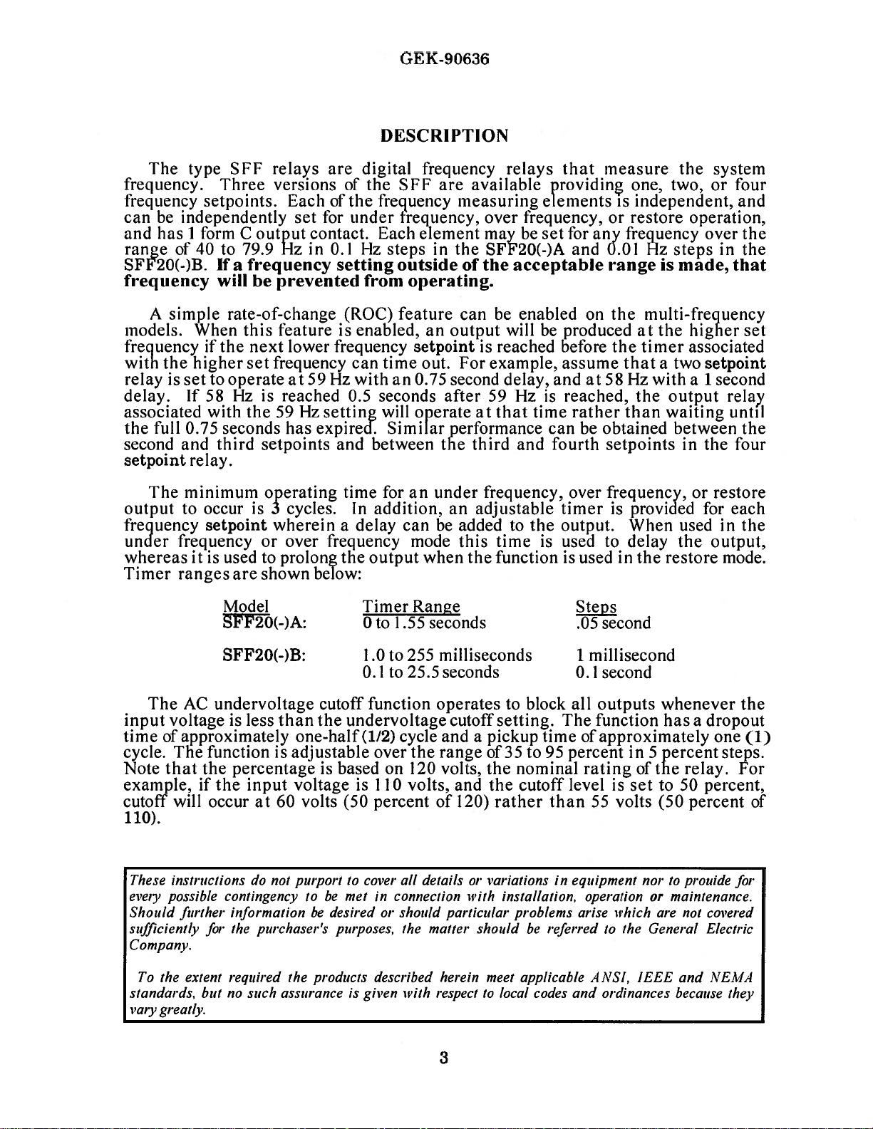
Mpdel
Sfl20(-)A:
SF’F20(-)B: 1.0to255
The
AC
undervoltage
input
time
cycle.
Note
voltageisless
Sapproximately
The
function
that
the
percentage
example,ifthe input
cutoff
evely
Should
sufficiently
Company.
standards,
vaiy
will
These
instructionsdonot
possible
funher
To
the
extent
gnat4y.
occurat60
contingencytobe
information
flu’
the
purchaseri
required
butnosuch
Timer
0to1.55
0.lto
cutoff
than
the
undervoltage
one-half
is
adjustable
voltage
volts
purport
be
the
products
assuranceisgiven with
(1/2)
is
based
is 110
(50
to
cover
metinconnection
desired
purposes.
25.5
function
cycle
over
on
volts,
percentof120)
all
or
should
the
described
Ranae
seconds
milliseconds
seconds
operatestoblock
the
120
cutoff
and a
range
volts,
and
setting.
pickup
535
the
the
rather than
details
or variationsinequipment
with
installation,
particular
matter
herein
respect
should
meet
to
local
The
time
to
95
nominal
cutoff
problems
referred
be
applicable
codes
SteDs
second
.05
1
millisecond
0.lsecond
all
outputs
function
dapproximately
percent
rating
level
is
55
volts
operationormaintenance.
arise
which
to
ANSI,
ordinances
and
whenever
hasadropout
inS
percent
d’the
set
to
50
(50
nortoprouide
are
not
the
General
IEEE
and
because
one
relay.
percent,
percent
covered
Electric
NEMA
the
(1)
stçps.
For
of
for
they
a
Page 4

The
relays
can
powered
be
from
GEK-90636
either
a
DC
or
AC
source.
External
Figures
1, 2
Table
The
SFF
device
is
conditions.
Under
Krequency
connections
and
3,
I
summarizes
series
required
to
the
respectively.
the
models
Model
SFF
201
202
204
of
frequency
for
the
accurate
SFF2O1,
SFF2O2
available.
Table
Case
Size
S2
M2
M2
APPlICATION
relays
can
detection
I
be
and
applied
of
under
SFF2O4
Set
Points
1
2
4
wherever
frequency
relays
an
or
can
be
extremely
over
frequency
seen
stable
in
under
The
conservation
important.
load
exceeds
in
danger
used
to
detect
the
loss
of
of
the
system
of
the
entire
overall
An
different
a.
ways:
Disconnect
successively
b.
Disconnect
so
that
Any
c.
Each
frequency
of
the
voltage
under
distorted
total
Longer
the
or
over
so
time
time
frequency
frequency
schemes where
If
a
system
generation,
of
collapsing.
this
condition
generation.
to
recovertonormal,
system
load
blocks
lower
blocks
some
load
combination
measuring
wave
frequency
as
to
affect
setting,
delay
settings
exceeds
trip
accuracy
disturbance
system
Under
and
Sufficient
will
be
facilitated.
conservation
of
load
frequency.
of
load
is
disconnected
of
the
against
a
crystal
before
the
period
is
possible
it
will
the
setting
feature
results
frequency
frequency
to
disconnect
load
or
near
scheme
in
in
several
above.
element
reference and
delay
the
of
for
the
make
for
of
and
repeatability
relays
must
normal
can
several
steps
as
each
in
the
timer
the
wave,
relay
this
at
the
in
loss
will
start
distributed
selected
disconnected
be
be
steps
on
time
SFF
is
and
to
less
likely
least
SFF
relays
of
generating
to
frequency.
arranged
with
a
time
step
compares
requires
started.
if
this
make
to
one
cycle
of
frequency
decay
system
to
each
basis
reached.
is
If
the
distortion
an
occur.
after
may
and
around
load
enable
to
In
this
trip
off
step
at
one
period
the
three
successive
input
incorrect
On
the
be
used
measurement
capacity
system
the
the
system
to
compensate
the
way,
selected
occurring
frequency
of
voltage
persists
measurement.
the
other
delay
in
load
such
that
may
can
remainder
restoration
load
at
level
cycle
each
cycles
wave
for
the
hand,
timer
is
be
be
for
in
a
of
is
if
is
4
Page 5

GEK-90636
started,
a
new
measurement
An
of
the
potential
not
good
section
voltage
when
to
the
this
the
zero
load.
condition
setting
then
this
A
substation
time
coordination
substation
frequency
the
combined
to
trip
and
load
would
sources.
of
the
under
The
power
For
high
the
down
drop
The
the
company
faults
speed
reclosure
during
in
relay
power
analyzed
the
open
arid
before
important
practice
and
use
and
frequency
circuits
and
often
A
frequency
any).
(if
load
are
decreased
with
lock
not
‘This
problem
frequency
SFF
relay
on
the
reclose.
to
the
frequency
could
system
to
determine
circuit
the
will
consideration
source
supply
to
that
relay
are
de-energized.
different
at
if
the
voltage
the
If
will
be
inadvertently
which
in
load
tripped
fast
a
out
operating
unnecessarily.
then
may
transmission
line,
Itisimportant
prevent
interruption.
that
be
used
before
period.
time
delay
be
started.
from
which
relay
a
to
disconnect
of
circuits
relay
stays
relay
has
is
a
shedding
out,
the
as
the
be
accomplished
could
also
both
trip
be
and
be
ends
damage
might
to
occur
trip
reclosing
the
amount
is
reached,
in
the
the
from
supplying
Rather,
rates
depending
connected
above
connected
disconnected.
large
amount
applications.
motor
motors
under
In
avoided
the
level
in
used
circuit
of
the
for
to
motors
An
SFF
during
incoming
the
takes
of
application
relay
makes
a
potential
load
on
motor
both
such
to
the
voltage
to
disconnect
of
load
would
were
slowing
frequency
an
unattended
simply
by
coordinating
by
of
the
an
industrial
that
utilizes
will
line
the
industrial
andlor
relay
the
breaker
place.
frequency
the
timer
of
frequency
its
source
another
load
the
voltage
on
the
characteristics
a
circuit
cutoff
load
motor
load
If
the
tend
down.
relay
may
station,
reenergizing
undervoltage
installation
high
be
tripped.
load
generators
at
the
plant
time
that
to
Each
decay,
will
immediately
be
relays
measurement.
that
is
connected
bus
section.
do
not
go
to
and
the
could
produce
setting
on
a
separate
may
present
transmission
maintain
to
This
slow
cause
restoration
the
settings
cutoff
that
speed
to
automatic
This
will
disconnected
be
that
could
the
the
be
transmission
plant
application
if
any,
that
is
It
For
zero
frequency
the
of
for
the
sources
the
decay
the
motor
the
of
the
function.
is
tapped
be
may
used
to
separate
will
will
reset
the
location
is
generally
to
one
example,
immediately
decay
circuit
an
output
time
delay
bus
section,
problem
a
to
voltage
of
voltage
while
breakers
of
the
motor
transmission
time
delay
off
reclosing.
followed
by
prior
have
to
occur
detect
line
have
slowed
is
open.
it
from
to
during
and
bus
the
and
for
the
of
the
be
of
a
a
to
Rate
of
Change
The
rate
relays,
or
a
The
F3
rate
and
rate
and
faster
of
position.
Over
over
Frequency
The
over
frequency
operation
load
rejection.
schemes
to
synchronous
would
during
be
used
off-line
of
change
usable
is
F4.
This
than
change
frequency
condition.
at
frequencies
be
used
speeds
to
operation.
only
feature
was
feature
Another
to
or
remove
feature
between
will
anticipated
is
enabled
function
For
example,
above
possible
protect
on
turning
supplemental
available
is
two
allow
when
may
rated
application
generator
a
gear.
adjacent
load
to
the
by
setting
be
used
it
can
speed
In
protection
5
only
shed
be
delay
the
anywhere
be
that
of
against
such
in
multi-setpoint
setpoints;
faster
timer
appropriate
that
used
to
could
the
be
over
accidental
schemes
that
is
i.e.,
if
the
settings
it
protect
caused
frequency
the
over
required
models
Fl
and
F2,
frequency
were
ROC
switch
is
desired
generator
a
by
an
function
energization
frequency
to
be
of
the
F2
and
decays
determined.
the
to
detect
to
against
inadvertent
at
function
enabled
SFF
is
sub
only
F3
at
IN
an
in
Page 6

It
should
fashion
enabling
be
that
the
recognized
a
loss
of
associated
I)C
when
the
to
off-line
GEK-90636
CAUTION
applying
relay
protection.
will
the
cause
over
frequency
the
output
function
relay
to
in
reset,
this
thus
Load
frequency
recovery
minutes.
can
that
Restoration
If
a
load
be
used
can
to
be
availability
determines
restoration
provided
related
by
to
emergency
setpoints
time.
the
system
Since
they
should
Reconnecting
the
do
not
momentarily
is
provided
whenever
below
enough
the
to
shedding
will
stabilize,
normal
the
As
to
automatically
restored
of
generation,
whether
program
a
timer
the
amount
conditions.
and
thereby
restoration
reset
reset
with
function
the
setpoint.
ride
over
program
likely
is
frequency
is
or
usually
external
of
staggered
be
loads
minimizes
as
a
result
restore
the
an
adjustable
is
This
momentary
and
through
to
be
approaches
begin
determined
either
not
the
incorporates
to
the
time
required
Also,
both
so
on
a
distributed
timers
will
of
output
time
subjected
delay
is
under
has
been
system
quite
the
by
slow
normal
load
the
locally
shed
load
SFF
to
the
time
all
that
the
possibility
be
set
transient
function.
delay
to a
frequency
adjustable
frequency
successfully
control
and
the
restoration
ability
ol-
through
can
substantial
relay.
add
generation
delay
of
the
basis
for
long
system
For
reset
and
will
may
extend
restore
process.
of
the
be
successfully
time
The
amount
and
load
is
not
also
minimizes
of
initiating
time
frequency
this
before
change
should
be
conditions.
implemented,
recover
over
a
function
The
system
system
interconnections,
restored.
delay,
of
time
or
to
close
the
restoration
reconnected
power
new
a
delays,
it
oscillations
reason,
the
from
contacts
kept
the
above
very
the
to
normal.
period
in
to
the
amount
serve
of
SFF
which
delay
tie
lines
frequency
at
the
swings
disturbance.
essential
is
that
restore
change
the
setpoint
brief,
only
system
The
several
relay
of
load
it.
The
A
load
must
to
use
during
same
across
that
may
function
state
long
be
is
to
The
rated
frequency.
restore
relay
may
provided
after
load
kept
energized
should
after
an
has
been
the
restore
restore
frequency
function
be
shortened.
to
control
shedding
de-energized.
be
under
frequency
restored.
function
If
output
until
continuous
the
the
has
all
During
will
setting
relay
To
restore
occurred
of
the
In
this
condition
normal
not
operate
of
will
prevent
output.
and
load
way,
has
frequency
the
function
variations
pick
up
this,
CC
when
that
was
the
restore
been
due
to
minor
6
will
most
in
normal
and
drop
contact
a
is
to
be
energized
it
is
desired
shed
has
output
detected and
conditions,
changes
likely
frequency
continually,
out
converter
to
restore
been
relay
until
CC
in
be
at
designated
by
an
load.
restored
will
the
load
will
be
frequency.
or
very
are
such
that
the
life
external
CC
should
which
at
only
be
operated
that
was
de-energized
close
of
CC
device
time
shed
and
to
the
the
is
be
it
Page 7

GEK-90636
SPECIFICATIONS
DC
Control
Nominal
Minimum
Maximum
AC
Control
Nominal
Minimum
Maximum
AC
Measurement
Nominal
Minimum
Maximum
Settings
Frequency
SFF2O(-)A:
SFF2O(-)B:
Repeatability
Timing
SFF2O(-)A:
SFF2O(-)B:
Repeatability
Voltage
48,
110,
Volts
37
280
Voltage
110-120
45
Vrms
132
120
Vrms
42
Vrms
132
125,
Volts
Vrms
Vrms
Input
Vrms
±0.002
±
220,
(35%
(110%
3%
250
of
nominal)
of
Hz
nominal)
Setpoint
Setpoint
Setpoint
Setpoint
Setpoint
40.0
40.0
to 1.55
0
1
to
0.lto
to
79.9
to
79.9
seconds
255
milliseconds
25.5
Hz
in
Hz
in
seconds
0.1
0.01
in
in
Hz
0.05
in
0.1
steps
Hz
steps
second
1
millisecond
second
steps
steps
steps
Undervoltage
Setpoint
Setpoint
Repeatability
Rate
change
of
Frequency
Frequency
Frequency
Environmental
Operating
-20°C
will
not
malfunction,
Storage
-40°C
Surge
ANSI
IEC 255
GE
RFI
35%
Accuracy
(multi-setpoint
1
to
2
to
3
to
to
+55°C
to+75°C
C37.90
(SWC
to
95%
±5%
±3%
frequency
frequency
frequency
95%
nor
95%
in
5%
of
setting
relative
be
relative
and
Fast
steps
from
models
2:
IN
or
IN
3:
4:
IN
or
or
humidity
damaged,
humidity
Transient)
based
35%
only)
OUT
OUT
OUT
in
on
l2OVrms
to
90%
(noncondensing).
ambient
up
to
(noncondensing)
nominal
65°C
+
Note
that
the
unit
7
Page 8

Burden
Model
SFF
Case
Size
Set
Points
GEK-9063
RATINGS
Table
48
II
Power
DC
125
Burdens
Supply
250
AC
VA
120
Measurement
AC
VA
Contact
Make
DC
AC
Target
amps.
The
front
of
only
is
necessary
Frequency
frequency
stated
201
202
204
Ratings
and
carry
Break
Break
277
Volts
supervision
following
relay
the
A
of
each
range,
60
25
to
three
that
S2
M2
M2
30
amps
Watts
VA
maximum
settings,
without
remove
or
setpoint
frequency
Resistive
ms
(40
unit
which
the
four
for
0.1
the
digit
to
1
2
4
1
second.
L/R)
Amperes
5
amp
must
need
front
thumbwheel
be
set.
setpoint
operate
SWFTI
be
for
pulling
cover
3.2
4.9
8.4
set
from
Note:
will
level
NGS
in
if
be
3.5
5.2
8.7
with
each
boards
the
relay.
switch
setting
a
prevented
6.3
8.0
11.5
than
less
application,
or
removing
on
the
is
front
made
from
8.1
10.6
15.7
0.6
are
the
operating.
volt
made
nameplate.
panel
outside
1
1
1
drop
from
allows
of
at
30
the
It
the
the
Function
modes
delay
Rate
the
It
of
rate
is
disabled
and
Time
delay.
Voltage
used
to
the
switches
A
of
operation.
the
Change
of
change
Delay
setting
The
Cutoff
choose
three
contact
(Multi
when
An
the
in
the
position
When
the
converter
frequency
function.
over
frequency
array
is
An
of
equal
array
undervoltage
UP
position.
slide
switch
restore
input
models
This
function
or
two-position
the
to
of
sum
two-position
cutoff
permits
mode
is
enabled.
restore
of
the
level.
is
only)
only
is
modes
toggle
switches
toggle
The
8
the
chosen
A
two
valid
switches
switches
cutoff
choice
the
position
are
in
of
timer
under
for
chosen.
allows
UP
the
calibrated
setting
under,
is
switched
recessed
frequency
setting
position.
is
equal
over,
switch
in
to
or
restore
dropout
to
selects
operation.
the
output
5%
steps
the
sum
is
of
Page 9
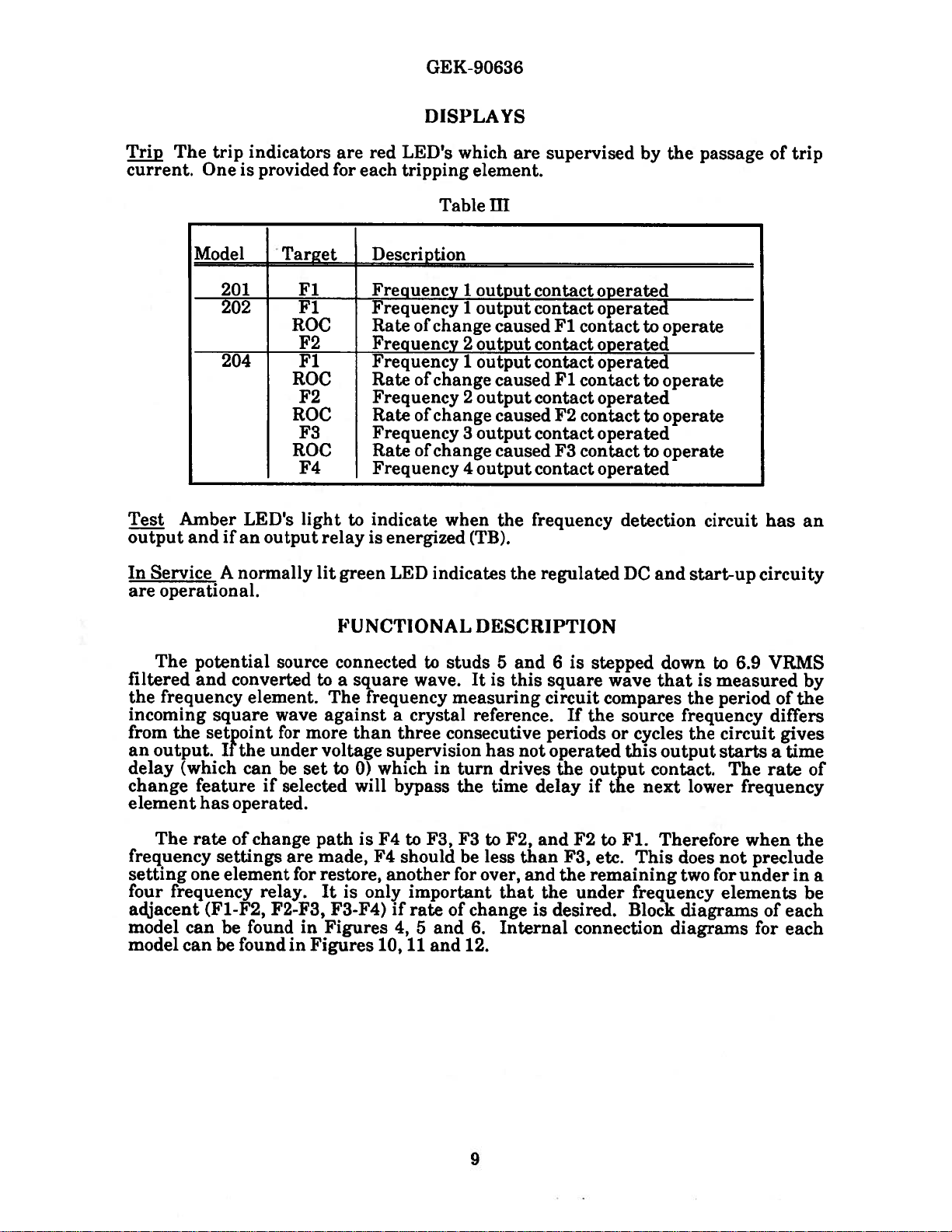
jp
current.
The
trip
One
indicators
provided
is
are
for
red
each
GEK-
DISPLAYS
LED’s
tripping
90636
which
element.
are
supervised
by
the
passage
of
trip
Test
output
In
Service
are
operational.
Model
Amber
and
Target
201
202
ROC
204
ROC
ROC
LED’s
ifanoutput
A
normally
Fl
Fl
F2
Fl
F2
F3
ROC
F4
light
to
relay
lit
green
FUNCTIONAL
Table
Description
Frequency
Frequency
Rate
of
change
Frequency
Frequency
of
Rate
change
Frequency
of
Rate
change
Frequency
of
Rate
change
Frequency
indicate
is
energized
LED
indicates
HI
1
output
I
output
caused
2
output
1
output
caused
2
output
caused
3
output
caused
4
output
when
the
(TB).
the
DESCRIPTION
contact
contact
Fl
contact
contact
contact
Fl
contact
contact
F2
contact
contact
F3
contact
contact
frequency
regulated
operated
operated
to
operated
operated
to
operated
to
operated
to
operated
detection
DC
operate
operate
operate
operate
and
circuit
start-up
has
circuity
an
The
potential
filtered
the
and
frequency
incoming
from
the
an
output.
delay
change
(which
feature
element
The
rateofchange
frequency
setting
four
one
frequency
adjacent
model can
model
can
converted
square
setpoint
If
the
has
operated.
settings
element
(F1-F2,
be
be
found
source
element.
wave
for
under
be
can
if
selected
are
relay.
F2-F3,
found
in
connected
to
The
against
more
voltage
set
to
pathisF4
made,
for
restore,
It
F3-F4)
in
Figures
Figures
a
square
frequency
than
0)
will
only
is
to
wave.
a
crystal
three
supervision
which
in
bypass
to
F3,
F4
should
another
important
if
rate
4,
and
5
10,
11
and
studs
5
and
It
is
this
measuring
reference.
consecutive
has
not
turn
drives
the
time
F3
to
F2,
be
less
for
over,
that
of
change
6.
Internal
12.
delay
and
than
and
the
is
6
is
stepped
square
circuit
If
the
periods
operated
the
output
if
F2
F3,
etc.
the
remaining
under
desired.
connection
wave
that
compares
source
or
cycles
this
contact.
next
the
to
Fl.
This
frequency
Block
down
to
is
measured
the
frequency
the
output
lower
Therefore
does
two
for
diagrams
diagrams
6.9
VRMS
period
circuit
starts
The
rate
frequency
when
not
preclude
under
elements
of
for
by
of
the
differs
gives
a time
the
in
be
each
each
of
a
9
Page 10

GEK-90636
CONSTRUCTION
The
components
removed
bottom.
from
The
completed
The
cover
prevent
all
unless
SFF2O1
by
the
The
case
panel
otherwise
are
The
printed
removing
horizontally
GE
part
circuit
boards.
components
The
output
cradle.
out
of
The
If
the
input
the
electrical
through
is
attached
from
cover
is
suitable
thicknesses
specified
shown
circuit
the
in
guides.
number
If
you
when
relays
a
relay
socket.
transformer
of
relay
the
case.
relay
connections
removable
the
front
to
being
for
semi-flush
to
two
up
on
in
figure
8
boards
four
screws
Each
286A2847P1
not
do
removing
are
mounted
requires
replacement
is
mounted
RECEIVING,
are
The
cradle
connection
of
replaced
inches.
the
order.
and
for
are
mounted
securing
board
card
have
a
the
boards.
HANDLING
mounted
is
between
the
case
until
mounting
A
Outline
SFF2O2
the
the
is
labeled
puller
puller,
card
in
sockets
unclip
on
the
on
locked
the
plugs
and
the
panel
behind
nameplate.
to
or
bottom
a
cradle
in
the
case
blocks
to
permit
includes
connection
on
panels.
thickness
and
panel
and
204
the
nameplate
correspond
other
be
on
the
suitable
careful
board
a
retaining
plate
AND
STORAGE
assembly
by
case
and
testing
two
plugs
Hardware
of
1/8
drilling
figure
The
to
not
fixed
of
the
that
latches
the
cradle
the
relay
interlocking
have
will
inch
dimensions
7.
and
can
boards
a
given
means
to
damage
to
the
and
wire
relay
cradle.
can
at
the
in
been
available
is
be
be
are
location.
remove
to
or
back
pull
easily
top
b1ocks
its
case.
arms
inserted.
assumed
for
accessed
mounted
bend
of
the
relay
be
and
are
that
for
the
Use
the
any
the
relay
This
discharge
components.
and
the
conditions
to
care
on
their
touching
generation
the
should
the
body
internal
any
These
cartons
relay
handling
promptly
installed
The
designed
examine
is
notify
relays
immediately,
chips.
General
The
relay
has
been
sustained
contains
currents
The
be
has
of
relays,
evident,
should
main
of
of
electrostatic
exercised
switches.
been
discharged,
components
the
when
to
protect
for
it
file
the
nearest
should
be
in
electronic
if
those
source
low
humidity,
when
The
not
any
damage
damage
a
General
be
stored
and
examined
shipment
components
currents
of
electrostatic
carpeted
discharge
removing
persons
by
on
included
them
handling
touching
the
modules.
as
against
sustained
claim
Electric
in
their
inaplace
that
ACCEPTANCE
and
tested
and
that
flow
floors
currents.
handling
and
some
part
damage.
once
at
Sales
original
is
upon
the
relay
that
could
through
discharge
and
the
surface
of
a
control
in
transit.
with
the
Office.
cartons.
free
from
TESTS
delivery
is
functioning
damaged
be
certain
currents
isolating
Where
the
module
these
modules
should
ground
at
panel,
Immediately
If
damage
transportation
If
the
moisture,
to
insure
by
terminals
is
the
shoes
are
conditions
to
make
make
potential,
will
be
upon
resulting
relays
dust
that
correctly.
electrostatic
of
human
body,
conducive
exist,
settings
sure
before
shipped
receipt
company
are
not
to
and
metallic
no
damage
the
that
in
of
from
and
be
a
10
Page 11

Visual
Remove
broken
Every
important
high
enough
brushes
circuited
A
drawout
12XLAI3A
a
disturb
Although
connections
‘Pest
any
Equipment
the
cracked
or
circuit
on
do.
during
shorting
this
are
relay
circuits
to
This
case
test
plug
made
parts.
in
the
engage
will
insertion
relay
plug.
bars
allows
to
from
drawout
may
This
both
its
with
the
prevent
of
in
greater
the
case
case
shorting
connecting
the
be
tested
plug
makes
the
case.
relay
GEK-90636
and
check
CAUTION:
has
bars
the
secondary
connection
without
connection
The
flexibility,
and
the
for
signs
an
auxiliary
that
the
plug
or
plug.
removing
12XLA12A
it
requires
external
of
auxiliary
test
circuits
it,
to
the
test
circuits.
physical
brush.
plug
from
from
relay
plug
shorting
damage
it
brush
before
the
panel,
only
may
jumpers
is
especially
the
being
and
also
such
be
by
does
be
as
bent
main
open-
using
not
used.
since
1
DC
2.
Variable
70
3.
Limiting
3KQ,
General
The
line
Each
generators.
When
manufactures
Testing
above
set
Relay
Test
Targets
The
panels).
frequency
frequency
lights
voltage
hertz
25
Testing
relay
can
frequency.
has
test
utilizing
with
or
Outputs
target
test
The
measuring
deviates
when
source
frequency
resistor,
Watts.
Considerations
be
tested
The
acceptance
a
section
variable
manual
line
frequency
below
the
LEDs
targets
test
from
the
timer
at
load
with
48V
box for
a
variable
rated
generator
or
test
for
line
frequency
frequency/voltage
for
specific
requires
line
frequency
are labled
indicatEWe
element
the
is
producing
(F-).
setpoint
to
250V
or
line
trip
have
operation
that
depending
Fl,TB
Test
status
The
for
3
an
output
with
less
than
frequency
target
rated
indicator
voltage/frequency
taken
into
testing
generators
account
and
refer
instructions
the
frequency
on
the
fault
F4,TB,
to
of
the
output
“F”
test
indicator
consecutive
to
operate
cycles.
the
ripple
5%
at
48
test.
generator
or
for
to
of
the
setpoints
being
see
output
to
Rated
both
variable
the
test
figure
relay
will
The
l2OVrms,
from
or
100Q-
with
contingencies.
frequency
equipment
test
apparatus.
of
the
relay
simulated.
19
17,
and
(TB)
“TB”
when
indicator
light
relay.
40
the
be
(front
the
the
to
Trip
Targets
The
the
are
trip
relay
reset
target
trips
with
LEDs
and
the
are
there
target
labeled
is
over
reset
lOOma
switch
F1,RC
through
or
by
11
to
the
F4,RC.
the
normally
removal
They
of
the
will
open
relay
latch
contacts.
power.
“on”
when
They
Page 12

GEK-90636
Relay
The
contacts
Tests
For
for
the front
SFF204
Test
the
Under
Note:
output
Over
The
relay
more
SFF2O1
SFF2O2
SFF2O4
The
T
Contacts
relay
for
the
following
front
relay
Frequency,
The
trip
contacts.
Frequency
will
than
three
Set
Point
Fl
Fl
F2
Fl
F2
F3
F4
relay
contacts
eachofthe
test.s
viewsofthe
view.
in
accordance
RateofChange
LEDs
will
Relay
trip
when
cycles.
Frequency
t
5Oor6Ohz
50
50
50
50
50
50
can
be
tested
and
consist
of
frequency
refertofigure
SFF2O1,
with
only
light
Tests
the
frequency
60hz
or
or
60hz
60hz
or
60hz
or
60hz
or
or
60hz
at
other
adjust
the
normally
measuring
9
for
and
204
respectively.
the function
or
Restore.
and
sealinif
under
Table
Switch
Settings
Mode
over
over
over
over
over
over
over
frequencies
inputs
based
open
(NO)
units.
test
connections,
set
for.
it
is
lOOma
test
exceeds
IV
ROC
-
out
-
out l.5sec
out
out
-
if
desired.
on
that
and
normally
and
For
the
SFF202
Such
as
of
current
the frequency
Time
Delay
1.5sec
1.5sec
1.5sec
1.Ssec
1.5sec
1.5sec
To
do
so,
setting.
to
flows
set
figure
Over
the
closed
17
and
refer
Frequency,
through
setpoints
Under
Voltage
Cutoff
35%
35%
35%
frequency
(NC)
to
20
the
the
for
Over
1.
Apply
2.
Set
the
frequency
frequency
setting
Verify
LEDs
to
have
Frequency
the
the
frequency
frequency
for
that
“Fl”
“F4”
light
tripped,
Test
rated
to
source
(0.5hz)
3
cycles
the
“F4”
to
after
as
With
supply
voltage
generator
59.5hz
115
at
above
plus
following
light.
the
indicated
Variable
at
for
60hz
Vrms
the
setpoint.
1.5sec
occurs
The
1.5
second
by
the
Frequency
between
(0.5hz)
and
between
to
produce
during
“TB”
time
trip
12
stud(1)
below
49.5hz
stud(5)
Maintain
test
delay.
targets.
Generator
for
an
output.
the
targets
and
the
50hz
and
over
and
And
stud(2)
setpoints.
rated
stud(6).
the
frequency
frequency.
the
trip
the
output
(either
For
setpoints.
Then
The
target
relay
polarity).
example,
Apply
increase
the
at
test
LEDs
contacts
set
the
the
higher
target
“Fl”
Page 13

3.
4.
5.
Remove
dropped
Reset
Remove
the
the
out.
target
the
input
LEDs.
supply
test
frequency,
voltage.
GEK-90636
and
note
that
the
contacts
and
LEDs
have
6.
Set
at
LEDs
outputs.
Over
Before
(0.5hz)
49.5hz
Apply
1.
2.
Apply
line
the
second
indicated
Remove
3.
have
4.
Reset
Remove
5.
undervoltage
the
step
1.
on
during
Frequency
applying
below
for
50hz
rated
the
frequency
“TB”
test
time
by
the
dropped
the
targets.
the
With
the
rated
supply
test
delay
the
input
supply
the
the
Test
With
the
line
frequency
line.
line
is
applied
targets
trip
out.
switch
undervoltage
over
frequency.
Single
or
single
input
This
simulates
voltage
between
frequency
verify
and
the
setting.
targets.
test
frequency,
voltage
setting
set
or
Line
frequency
that
at
ll5vrms
that
trip
And
to
at
you
stud(1)
the
target
the
and
95%,
and
there
95%
The
undervoltage
Frequency
source,
use.
an
over
and
between
test
LEDs
output
that
note
repeat
should
set
the
Such
frequency.
stud(2),
stud(5)
target
relay
“Fl”
LEDs
to
contacts
the
the
above
be
cutoff
frequency
59.5hz
as
non
and
“Fl”
“F4”
contacts
no
trips,
will
polarity
stud(6).
to
light
have
and
test
or
disable
setpoint(s)
for
60hz
sensitive.
“F4”
after
tripped,
test
starting
target
and
As
the
light,
the
1.5
LEDs
all
as
Set
6.
at
LEDs
outputs.
3I’F1J1
SFF2O2
204
SFF
.—.
The
relay
r
the
step
Set
Point
Fl
Fl
F2
Fl
F2
F3
F4
undervoltage
1.
With
during
the
T
Frequency
t
50
50
50
50
50
50
50
I
can
ne
tested
and
switch
the
undervoltage
over
or
60hz
60hz
or
or
60hz
or
60hz
or
60hz
or
60hz
or
60hz
at
adjust
frequency.
I
other
frequencies
the
setting
Table
Switch
Mode
under
under
under
under
under
under
under
inputs
to
set
The
Settings
-
based
95%,
at
95%
undervoltage
V
ROC
out
-
out
out
out
---
if
desired.
on
-
and
there
-
that
repeat
shouki
-I
—
To
setting.
the
cutoff
Time
Delay
l.5sec
l.5sec
l.5sec
1.5sec
l.5sec
1.Ssec
l.5sec
do
be
so,
above
no
trips,
will
set
the
test
disable
Under
Voltage
Cutoff
35%
35%
35%
frequency
starting
or
target
all
13
Page 14

GE
K-90
636
Under
rphe
than
Under
1.
2.
3.
4.
Frequency
relay
three
Frequency
Apply
Set
the
frequency
frequency
lower
Verify
LEDs
“F4”
to
have
Remove
LEDs
Reset
will
trip
cycles.
rated
the
frequency
frequency
source
setting
that
“Fl”
light
tripped,
the
have
the
targets.
Relay
when
Test
supply
to
(0.5hz)
to
the
to
“F4”
after
as
input
dropped
‘l’ests
the
frequency
With
Variable
voltage
generator
60.5hz
ll5Vrms
at
below
produce
following
light.
the
indicated
test
out.
between
at
for
60hz
between
the
rated
an
output.
occurs
“TB”
The
1.5
second
by
the
frequency,
under
test
Frequency
stud(1)
(0.5hz)
and
50.5hz
setpoints.
during
test
time
trip
targets.
and
is
Generator
above
for
stud(5)
the
targets
delay.
note
below
and
the
50hz
and
Maintain
under
that
the
stud(2).
setpoints.
rated
stud(6).
frequency.
and
And
the
setpoint(s)
the
the
trip
the
output
contacts
For
setpoints.
Then
frequency
The
target
relay
and
for
more
example,
Apply
decrease
test
LEDs
contacts
test
the
the
at
the
target
“Fl”
target
set
5.
Remove
6.
Set
at
target
all
Under
Before
above
Appiy
1.
2.
Apply
the
light,
the
as
Remove
3.
LEDs
4.
Reset
Remove
5.
the
undervoltage
the
1.
step
LEDs
outputs.
Frequency
applying
the
frequency
the
the
line
frequency
the
1.5
second
indicated
the
have
the
the
supply
With
during
the
rated
test
“TB”
by
input
dropped
targets.
supply
Test
supply
or
test
time
the
voltage.
switch
the
undervoltage
the
With
line
input
line
frequency
applied
is
targets
delay
trip
test
out.
voltage
setting
under
Single
or
single
used.
This
voltage
and
setting.
targets.
frequency,
to
set
frequency.
or
Line
frequency
simulates
between
at
ll5vrms
verify
the
that
trip
And
and
100%,
at
100%
The
Frequency
source.
an
stud(1)
the
target
the
output
note
that
and
repeat
there
undervoltage
Set
under
and
(2).
between
target
test
LEDs
relay
the
the
above
should
cutoff
the
setpoint(s)
frequency.
stud(S)
LEDs
“Fl”
to
contacts
contacts
be
and
“F4”
and
test
no
will
stud(6).
“Fl”
light
have
test
starting
trips,
disable
(0.5hz)
to
“F4”
after
tripped,
target
or
As
6.
Set
at
step
target
all
outputs.
the
undervoltage
1.
LEDs
With
during
switch
the
undervoltage
the
under
setting
frequency.
14
to
set
100%,
at
The
and
100%
undervoltage
repeat
there
the
should
above
be
cutoff
test
no
will
starting
trips,
disable
or
Page 15

GEK-90636
Rate
The
of
rateofchange
frequency
frequency
Example:
1.5
delay
a
seconds
change
F’F2U2
SFF2O4
The
t
relay
Change
change
setpoints.
seconds.
of
the
from
Set
Point
El
F2
Fl
F2
F3
F4
can
Fl
1.5
relay
Fl
(ROC)
feature
is
faster
is
set
If
the
seconds.
would
to
F2
[
Frequency
t
5Oor6Ohz
50or60hz
50
50
50
I
50
tested
be
and
for
Multiple
allows
and
to
59.8,
frequency
But
trip
was
faster
or
60hz
or
60hz
or
60hz
or
60hz
at
other
adjust
the
larger
F2
is
were
if
the
without
Switch
F
frequencies
the
Setpoint
relay
set
to
to
frequency
than
Table
Mode
under
under
under
under
under
under
inputs
to
in
magnitude
58.0,
from
go
waiting
the
time
VI
Settings
based
Models
trip
and
60
was
delay
ROC
in
-
in
in
in
-
if
desired.
on
faster
the
to
to
for
that
Only
than
the
time
59.7hz
change
the
of
Fl.
Delay
1.5sec
0.Osec
1.5sec
1.2sec
0.8sec
0.Osec
I
To
setting.
its
limits
delays
only
time
Time
do
set
from
delays.
so,
Fl
set
time
set
on
would
60
delay
on
Fl
and
to
58hz
The
Under
Voltage
Cutoff
35%
35%
H
the
frequicy
if
the
successive
F2
are
trip
after
.25
in
rate
of
It
is
essential
normally
Rate
1.
Apply
2.
Set
the
frequency
frequency
When
test
(The
The
“F4”
After
Remove
3.
LEDs
4.
Reset
5.
Remove
open
of
Change
rated
the
frequency
the
target
rate
“RC”
light
1.5
have
the
the
that
relay
contacts
Test
supply
frequency
to
source
(0.5hz)
frequency
LEDs
of
change
trip
targets
in
delayed
a
seconds
the
input
dropped
targets.
the
supply
trip
targets
for
Variable
voltage
generator
60.5hz
115
at
below
has
“Fl”
has
LEDs
all
test
out.
voltage
are
for
this
test.
Frequency
between
at
for
60hz
Vrms
the
between
setpoint
been
“F4”
to
overridden
light
with
sequence
should
frequency,
enabled
stud(1)
(0.5hz)
and
50.5hz
with
reduced,
the
and
the
no
according
lit.
be
and
by
Generators
above
stud(5)
zero
verify
“TB”s
set
delay,
note
and
for
time
and
to
the
time
their
that
lOOma
stud(2).
the
50hz
and
that
light
delays
the
of
setpoints.
rated
stud(6).
delay.
the
following
with
on
trip
time
the
contacts
current
For
setpoints.
Then
with
the
TB
target
delay
through
example,
Apply
decrease
occurs.
time
no
outputs).
LEDs
settings.
and
test
delay.
“Fl”
Note:
target
the
set
the
the
The
to
15
Page 16

6.
Rate
the
Set
step
at
LEDs
outputs.
of
Change
undervoltage
With
1.
during
the
‘Pest
switch
undervoltage
the
under
for
Single
GEK-90636
setting
frequency.
Line
or
100%,
to
at
set
The
Frequency
and
100%
there
undervoltage
repeat
should
the
be
cutoff
above
no
will
test
trips
starting
or
disable
target
all
Before
above
Apply
1.
Apply
2.
the
target
change
The
to
After
Remove
3.
4.
5.
6.
the
frequency
“RC”
“F4”
1.5
LEDs
Reset
Remove
the
Set
step
at
LEDs
outputs.
applying
frequency
the
LEDs
has
supply
test
“Fl”
overridden
rated
trip
in
light
seconds
input
the
dropped
have
targets.
the
supply
the
undervoltage
With
1.
during
the
input
voltage
frequency
line
been
has
to
target
delayed
all
test
voltage
undervoltage
the
under
the
lineorsingle
used.
between
at
applied
the
and
“F4”
set
light
time
the
LEDs
sequence
LEDs
should
frequency,
out.
switch
setting
frequency.
frequency
stud(1)
ll5vrrns
verify
“TB”s
delays).
with
according
be
and
to
set
Table
no
lit.
100%,
at
The
VII
that
light
delay,
note
100%
source.
and
stud(2),
between
the
with
stud(5)
following
no
and
their
to
the
that
repeat
and
there
should
undervoltage
Set
time
the
time
contacts
the
non
and
trip
delay
the
be
cutoff
setpoint(s)
polarity
stud(6).
occurs.
delay.
(The
target
settings.
and
above
no
test
trips
will
(0.5hz)
sensitive.
When
The
rate
LEDs
Note:
target
test
starting
or
target
disable
test
of
“Fl”
all
SFF’20
SFF2O2
SFF2O4
The
t
Restore
The
pins
to
Set
Point
1
Fl
Fl
F2
Fl
F2
F3
F4
relay
Relay
restore
10
and
can
circuit
20
t
tested
be
Tests
energized.
is
Frequency
60hz
or
50
5Oor6Ohz
60hz
or
50
or
60hz
50
or
60hz
50
60hz
or
50
5Oor6Ohz
at
and
adjust
only
will
other
the
produce
Switch
Settings
Mode
restore
restore
restore
restore
restore
restore
restore
frequencies
an
based
output
inputs
16
ROC
-
out
-
out
out
out
-
if
desired.
on
if
that
the
Time
Delay
1.5sec
1.5sec
1.5sec
1.5sec
l.5sec
1.5sec
1.5sec
To
setting.
contact
so,
do
converter
set
Under
Voltage
Cutoff
35%
35%
35%
the
frequency
connected
Page 17

GEK-90636
Restore
L
Apply
2.
Connect
power
3.
Set
the
frequency
test
Next,
“Fl”
are
4.
Remove
5.
Remove
6.
Set
at
LEDs
Restore
Test
rated
supply
the
frequency
targets
decrease
to
“F4”
closed)
the
undervoltage
step
1.
during
Test
With
supply
a
DC
source
voltage
frequency
to
source
‘Ti”
the
will
for
the
the
input
the
supply
With
the
the
With
Single
Variable
voltage
rated
will
generator
60.5hz
at
ilSVrms
to
“F4”
frequency
go
out
1.5
second
test
voltage
switch
undervoltage
test.
or
Frequency
between
at
48V
suffice
at
for
60hz
and
“TB”
(0.5hz)
but
the
delay
frequency.
setting
The
undervoltage
Line
Frequency
Generator
to
if
it
(0.5hz)
and
between
LEDs
“TB”
setting.
to
set
stud(1)
250V
is
DC.
above
50.5hz
stud(5)
are
below
LEDs
95%,
at
95%
cutoff
and
between
the
for
50hz
and
lit.
the
setpoint.
will
and
there
will
stud(2).
stud(10)
setpoints.
rated
stud(6).
remain
repeat
should
disable
setpoints.
The
lit
the
above
be
all
and
stud(20).
For
And
test
(output
no
trips
outputs.
example,
Apply
note
that
target
contact(s)
test
starting
or
Your
set
the
the
LEDs
target
1.
2.
3.
4.
5.
Before
setpoints
Apply
Connect
power
Apply
note
that
With
(0.5hz)
go
out
closed
Remove
Remove
Set
the
at
step
LEDs
applying
(0.5hz)
rated
supply
the
for
a
the
the
test
above
but
the
the
the
supply
DC
voltage
test
test
or
the
the
1.5
input
supply
undervoltage
1.
With
during
the
the
line
below
the
voltage
source
rated
will
line
frequency
targets
line
rated
“TB”
second
test
“F”
frequency
line
LEDs
time
frequency.
voltage.
switch
the
undervoltage
test.
The
INSTALLATION
or
single
frequency
between
at
48V
to
suffice
and
if
at
still
it
li5vrms
“TB”
applied,
frequency.
will
remain
delay
setting.
setting
set
undervoltage
frequency
used.
stud(1)
250V
is
and
between
DC.
between
LEDs
are
increase
The
test
lit
and
to
95%,
and
at
95%
there
cutoff
will
PROCEDURE
source.
stud(2).
stud(10)
stud(5)
lit.
the
target
the
output
repeat
should
disable
Set
and
and
frequency
LEDs
contacts
the
above
be
no
all
the
stud(20).
stud(6).
setpoints
“Fl”
to
test
trips
outputs.
frequency
Your
And
“F4”
will
will
stay
starting
or
target
to
The
relay
vibration.
dimensions
It
are
should
should
shown
be
installed
be
mounted
in
figures
in
on
7
a
a
and
clean,
vertical
8.
17
dry
surface.
location,
The
free
from
outline
dust
and
and
panel
excessive
drilling
Page 18

GEK-90636
Surge
than
relay
should
protection
positionofthe
Electrical
The
The
Ground
case
AWG
case
be
test
No.
and
as
from
Tests
establishment
Settings
Frequency
Mode
of
Rate
Time
Change
Delay
stud
short
case
given
of
should
12
copper
the
surges.
your
Set
buttons
Choose
position
ON
switch.
Set
UP
be
wire
surge
grounding
suppression
as
possible,
Figure
in
the
procedure.
the
desired
on
Under,
multi-setpoint
the
desired
position.
permanently
or
equivalent.
preferably
23
showsarear
stud.
Acceptance
frequency
the
switch.
Over
slide
switch.
time
connected
networks
Section
or
models,
by
summing
This
in
10
inches
viewofan
for
each
Restore
select
ground
to
connection
the
relay.
or
can
be
setpoint
operation
INorOUT
the
setting
byaconductor
is
made
The
surge
less,
to
provide
S2
case
used
as
pushing
by
by
byatwo
of
to
ground
illustrating
a
guide
the
recessed
a
position
the
toggles
not
ground
maximum
in
and
+
three
slide
in
less
the
lead
the
the
-
the
Undervoltage
The
power
The
heat
regulated
and
SHOULD
instruments
isolated
hazard.
The
card
extender
tests.
REMOVE
printed
result
circuit
in
damage
Set
supply
sinks
DC isatthe
from
are
NOT
connected
ground
board
ALL
power
boards
to
the
desired
TROUBLE
in
this
at
the incoming
same
BE
CONNECTED
to
and
part
from
or
output
and/or
voltage
CAUTION:
relay
monitor
observe
is
potential
the
number
CAUTION:
relay
misoperation
before
relays.
summing
by
SHOOTING
not
isolated
potential.
the most
as
TO
signals
proper
Further
GROUND.
within
techniques
0215B8031G1
removing
Failure
of
the
to
relay.
the
togglesinthe
from
the
the
negative
Make
the
is
required
or
inserting
observe this
incoming
common
power
sure
relay
avoid
to
to
UP
terminal
that
suitably
are
a
perform
any
caution
position.
power.
of
the
test
shock
these
of
the
may
18
Page 19

GEK-90636
The
defective
following
of
known
set
a
Begin
Refer
The
letters
on
The
at
extender
indicates
by
to
board locations
and
internal
the
block
selected
circuit
paragraphs.
settings.
setting
SFF
Model
201
202
204
figures
part
the
connections
diagrams
points
board.
a
failure
the
Fl
0.1
0.2
0.4
17
The
in
may
The
relay.
Line
through
are
number
in
figures
in
the
failure
that
identified
be
tests
uency
Fre
F2
0.1
0.3
identified
0.2
22 for
of
the
diagrams
14,
relay.
of
module.
F3
are
based
TABLE VIII
plus
F4
0.1
viewsofthe
by
letters
printed
in
and
15
rllhe
points
the
signal
fo1lowin
by
on
Mode
Under
Under
Under
circuit
figures
16
give
to
using
line frequency
relay
Ofl
the
assembly
10,11and
voltages
the
are
meet the
the
Rate
Change
Out
Out
with
right
connector
levels
procedures
as
of
Under
Voltage Delay
50%
50%
50%
and
without
side
of
the cradle.
for
each
location
12.
and
waveforms
pin
shown
outlined
the
input
Time
0.1
0.1
0.1
nameplate.
a
to
numbers
on
the
in
and
These
are
given
found
be
on
diagram
the
on
the
The
signals
loading
logic
9.6
low
to
A
voltage,
amplitude
is
CAUTION:
any
of
caution
When
replacing
internal
Perform
Considering
is
important
interval
relay,
and
enough
should
circuits.
the
a
signal
is
nominally
is
between
12
volts.
REMOVE
the
printed
result
may
connections
the
acceptance
PER1O1)IC
that
between
the
users
experience
measured
Remember
with
this
80
circuit boards
in
module
a
diagrams
the
vital
a
periodic
periodic
experience
to
with
the
regulated
an
amplitude
volts.
100
2.4
percent
is0to
and
SKRVICING
ALL
power
and/or misoperation
in
before
to
the
figures
returning
ANI)
damage
check
tests
CJ-1ECI{S
roleofprotective
program
test
with
the
will
periodic
test
checks
select
high
of
from
or
part
vary
interval
input
DCisnot
between
A
logic
of
the
regulated
relay
output
number
10,
11
the
ROUTINE
relays
followed.
be
depending
testing.
impedance
isolated.
and
zero
high
is
defined
DC
before
relays.
and
location
12
and
relay
before
service.
to
MAINTENANCE
in
the
operation
upon
Until
best
suited
instruments
20%
voltage,
removing
Failure
of
the relay.
inserting
It
is
recognized
environment,
the
user
to
of
of
as
to
as
a
their
the
regulated
signal
a
nominally
or
observe
shown
power
has
accumulated
avoid
to
whose
inserting
this
on
the
module.
system
that
type
individual
DC
this
the
it
the
of
19
Page 20

GEK-90636
requirements
at
an
interval
is
It
recommended
enable
Electric
number
required.
Company.
the
the
When
Company.
if
is
It
recommended
card
be
it
of
prompt
ordering
known,
Table
Should
replaced
is
suggested
from
one
that
replacement
renewal
Specify
and
the
IX
lists
that
printed
a
with
to
two
sufficient
the
complete
the
part
renewal
spare.
a
the
that
years.
RENEWAL
of
any
parts
circuit
address
quantity
numbers
points
quantities
that
required,
model
for
parts
card
only
become
listed
PARTS
are
broken
the
number
the
be
under
renewal
of
or
nearest
name
of
the
most
common
obtained
inoperative,
acceptance
parts
damaged.
Sales
of
Office
the
relay
replacement
from
it
test
carried
be
of
part
wanted,
for
which
General
the
is
recommended
the
be
in
the
parts.
checked
stock
General
the
part
part
Electric
that
to
is
Since
p.3,
Overfrequency
Tests,
the
last
undervoltage
AC
steps6and
edition,
Tests
5
changes
cutoff
step
6.,
p.15,
respectively,
have
p.21,
been
range,
Rate
of
Part
made
p.7,
Change,
number
20
in
the
following
Undervoltage
example,
of
SFF2O1
places:
specifications,
p.17,
Load
Power
Supply.
p.13,
Restoration
Page 21

GEK-90636
Model
SFF
201
202
204
201A
202A
204A
202A
204A
201B
202B
204B
202B
204B
201
202
204
201
202
204
201
202
204
201
202
204
201
202
204
201
202
204
201
202
204
201
202
204
201
202
204
201
202
204
Function
Power
Power
Frequency
Frequency
Frequency
Frequency
Frequency
Frequency
FrequencyF2
Frequency
Frequency
Frequency
Undervoltage
Mother
Mother
Mother
Output
Target
Potential
Lower
I
Lower
Upper
Upper
Upper
Upper
Cover
Cover
TABLE
Supply
Supply
Fl
F2
F4
Fl
Fl,
Fl
F4
Fl
Fl,
board
board
board
relay
Reset
Transformer
Cradle
Case
Block
Cradle
Cradle
Case
Block
Case
Block
F2,
F2,
Switch
Block
Block
Block
F3
F3
IX
Part
I
J
0184B8624G2
0184B8624G3
06418058G644
06418058G645
006229807G59
006229807G60
number
0184B6385G-1
0184B3856G-2
0184B3856G-2
0184B8922G-1
0184B8922G-2
0215B8404G-l
0215B8404G-2
0184B8921G-1
0184B8611G-1
0184B89250-1
0184B8925G-2
0246A9826P-3
0246A9920P101
0367A0265G79
0184B8624G1
06418058G643
21
Page 22

cc
cc
C-)
0
U,
0)0
.-‘
W
(.J
0
LA)
I
-
5
0.
0.)
0.
C
•0
.
.0
‘0
0
U‘•0
—
—
Cd)
a)
C
Cl
Cl
C
C.)
a)
tui
-
1
a)
‘-4
Page 23

cC
C
C
-F’
I
I
d
—
‘ii
c5
0’
—
C
o
n
t)
(0
I
—
I
‘-5
as
—
a
0.
C
0
H
B
B
•
-I
1)
C’4
C,
c1
>4
C
C,,
C
Page 24

GEK-90636
1
g
h
C,
I-
U
&
-
&
C
ci
1
I
g!
1
ri
HH
It
UI,
Li
“1
CU
0
0
ceo
C
U
——
Figure
3
(0286A2810-1)
Externa’
connection
24
diagram
for
the
SFF2O4
Page 25

Trip
Target
C)
7
Fl
+
C
8
9
28QVDC
to
36
CD
alarm
operated
eupply
3
Normally
Power
r—O
_.L
±
I
Power
I
I32VAC
28OVDC
or
to
I
5
-3
(-)
-3
01
01
i2OVAC
I
CD
C12
to
42
35
2
C
Page 26

CD
7
8
Fl
9
cz
12
F2
11
C20C
10
a1ar
operaed
ppIy
3
NormLy
pcwer
r—O
4
‘-
i32VAC
Dr
to
42
5
-J
C)
-J
c1
0
Page 27

GEK-.90636
I
3
4.
i—
Pcwer
NDrI’afly
Power
Sup1y
36
t
or
I32VAC
42
t
Figure
aIrm
supp)y
oprat.d
6
(153D7677
[1])
Block
diagram
for
the
SFF2O4
27
Page 28

GEK-90636
[6
4
312
1
4MM
PANEL
6
•
625
168MM
SEMI-FLUSH
LOCT
ION
SURFACE
CUTOUT
DRILLED
5/16—18
SURFACE
MAY
REPLACE
HOLE
STUDS
MTG,
PANEL
FLIP
SEMI-FLUSH
TYPICAL
INCHES
MM
FRONT
DIM
DRILLING
MOUNTING
VIEW
Figure
VIEW
FOR
7
SHOWING
SURFACE
(6209274
for
ASSEMBLY
MTG.
[6j)
the
SFF2O2
76MM
ON
Outline
28
STEEL
and
and
OF
HARDWARE
PANELS
mounting
SFF2O4
PANEL
FOR
SURFACE
FRONT
dimensions
DRILLING
MOUNTING
VIEW
Page 29

GEK-90636
10312
P61MM
1/4
DRILL
6
68MM
1
625
125
1.
29MM
PANEL
SEMI-FLUSH
1•
LOCATION
032X3/8
187
6.
157MM
SURFACE
75
19MM
10-32
K__S
,—K2)
FOR
J
‘/
CUTOUTS
DRILLE]J
5/16—18
SURFACE
191715
00000
00000
20
18
STUD
NUMBER
97531
00000
00000
10
8
BACK
MAY
14
16
I
4
6
VIEW
REPLASE
HOLES
STUDS
MTC.
131:
12
NC
2
562
218
5MM
FOR
TYPICAL
INCHES
MM
-----
cuilUl
PANEL
SEMI-FLUSH
DIM.
DRILLING
FRONT
MOUNTING
VIEW
VIEW
FOR
I-
10.000
254MM
CA
SHOWING
SURFACE
DRIL.
5/8
HOLES
2
1
5MM
3,0
76MM
ASSEMBLY
MIG.
ON
•3/4
20
OF
STEEL
DRLL
HOLES
1.8MM
5/16-18
HARDWARE
PANELS
PANEL
FOR
STUD
DRILLING
SURFACE
FRONT
.500
12MM
<TYPICAL)
MOUNTINE
VIEW
Figure
(6209272
8
[7])
Outline
and
29
mounting
dimensions
for
the
SFF2O1
Page 30

GEK-90636
-:3
Li
“-I
;Th
Li
a;
4
a
D
ID
ft
L.i
Lfl.Li
(a_,
La
X’
-(—.1
J
Li
Ui
UI
_i
a
I.)
I-
‘_J
I.
IF
)Li
-
ft
—
—
—
—
(I
(a
—
—
ft
ft
fl
I,
(a
—
Ii•Z
ID
a
C
•1
—rn
C
(ti_In-)
LLL(
-:1
_F(aIUIII—
UJLIa4
•1
I
Ga-CL)
ft
a
4
a
C)
ft
3
4
I
(a
“I
F
o’n
ID
-I—
ad
a,
Ii
I.
4
-J
Li
ft
€H
:-K)---
(
-->
H
--K-()-H
‘4
o
H--K--1I’
-III
H”
I
CF—Li
IF
F-
ra
$
ft
F
F
(U
zzu
C
ft
-JCIU_
F
Li
z
d
UI
Li
ata-t
41_il’
adD:
(4>--.
Li
.1
ft_i
ft
.JftF-.
$4
Li
CtLIC)
I_i
I-
F-
LizCLI
C)
ftLi4
ft
H
.Lft
-
[-F-
-
UJ(a
a
ftZ(a
Li
—
—
Li Li
Li
LiftI_i_i
C)
ft
H
a
—
r
‘Li
ri
ft_
L_
zi
z-
_
F-—”
IL.)
Ift_iH
-t.
•LII
I—i
TI
,a-’_
L___J
_1
T—-L
H
L
—J
CI
D
a-I
Ca
ri
L
I
L
r
—
r—J—-—;1
r
I
zz
c3)
————-----—()
Liii
-r)
L__
I
Z1
a
lz
‘—a_____________
ua)
‘—I
O
—
>-I
(l
a
F->
LiLi
La
Lift
>
WH
-a-’.,
L
Li
>
F-
Figure
(1
79C7527-2)
9
Test
30
connections
for
the
SFF
Page 31

CD
C
C-)
0)
CD
C
0
C)
a
-,
:2)
CD
*
-
El
zO
I-I
CD
©
C
—
0
CD
C
I-.
Cl)
I.,
CD
Cl)
C
Page 32

GEK-90636
Case
S
77J’
24
Jijs
0 45578
2
z.
333435
6
2
045
00C3tIIJli15I6I0lO1902122?12.L25:500;n?9io,l3?
9
12
lit
4
142434
37
39
33
500
40
45464140495054
2Ii04
9
clii
al
a_a_a
15
I.9H155,4710192020
1520
11iS07
10
a_a_a_F
17
2223
53145556
50
202?232’25
(3
:
:
a
0
Cl
‘I
CS
202M
29
1570
27 28
a.a_s_j
64 12
09 70
i
Ii
.
52
151960
25
7t51490?7
121
C
32
3J
Lj
Feset
IThE
Stud
r
4I2
[
n
Case
Gnd
Internal
3&3734
39j40
4
5
078 58058I)1)4445
-I-
Figure
connections
44
434304
Ili:
iE
49464744
‘II!,.
LI
11
(0183B4490
diagram
•1
4930
l9203l40202029a.21260’9703t32l
4047II
I
9O1
-,
a
15
0
7
H
i
for
•6
0
[4])
the
-
1
In
u
SFF2O2
Lj,lr.017.V8
to
Cast
‘T
HC
F
ó
00
1,tp
32
Page 33

99O6-NID
-
1
rolto
IIJ0I1
10
z
c
r
ft
::-
H
4.
69
09
II
07
;
i,ororqtttttlcertltt
6
:::
T
“T
SIT
-
I
-
I
I
L9t909L5t0mtt
t]i””
L’
(?5
0556
IS
09160969
95
(5
09
509
0’
69 69
99‘06?
06
96
-?7
0?
00
00965000
6000
00?96
51
II
II
91
II£126
II
0166
T:r
U
gE,o9,oo26c.s1;9c9c,;r;z;lcoc6rg1orsr;1rrrr09
El0C
lI6flIt
0
:ijs0
pns
96 £0
0
I
:;
;
I
j
1_I
9 £
•
a
—
U
1
06 06
16
0660L9 6
—
—
—
1’’I
I
91SIII
I—a-rn-
.
T
SUOT1UUO)
till
10
026299
00
0?I?0?
66II16
:
([c]
T6’fI8IO)
wninip
.1OJ
rot
L_
00
It0060 90
rS
fl
1dP
If
L-J
tOLIS
10u.nbl,J
PA11P1
loll
L’
09
19
0999
09 05
56
55
95 05
05
65
0969
09 19
90 99
006’09
9
090060
00
96j56
Page 34

BLOCK
CONNECTING
C)
PLUG
BAR
BLOCK\
CONNECTING
TERMINAL
SHORTING
BRUSH
ON
BRUSH
MAIN
THE
\
BRUSH
MAIN
PLUG
CONNECTiNG
AUXILIARY
BRUSH
ENGAGING
AUXILIARY
NOTE:AFTER
ENGAGING
BEFORE
BLOCK
INCH
TERMINAL
THE
TRAVELS
C
C
ci
c.z
C12
C
C,,
C
Page 35

C)
7
El
TICCE
\
:.i)
/
CONTICT
l.LN
ENOHCIZLU
HIGH
CONVEG1ER
LOGIC
p
•
PIN
I
S
SETTING
I
ISEN
THAN
CT
HIGH
LT
GREATER
I
7
I
17
.
p
EGVCLTA31
P1N57
GESTC,E
V-f-—
&%
L_____
DECTECTOR
—•
2I%V+—-
P1N43
cONIN
I
I
Ii
P1N.iB
L
CT
PCI
y,EN
ACTUATEG
HIGH
SITCH
LOLIC
POSITION
I
C
POSITION
BOARD
B
BO-IflO
DIGITAL
I-SET
PIET
ALL
PIN3
-G-i
LOC
-
10%
÷/
—03
12V
—
+
ODARUS
LCI:
LOGlu
20%
IIjscH
CPERATED
SuPL’
PCER
NORMALLY
L_
04
4..
-
COMMON
ILL
PINI
fr.
ENDInGS
CO’O
TO
30
AL
‘D
42
Cl)
C4Z
C?1
ArcALO
1
r
C
C
2t30.’DC
TO
L..TEP
35
5.OV-.iS
I
I
I
10
ij
‘1
I
20
r
°-‘
C
C
Page 36

Lxi
CD
C)
7
B
Fl
9
C
13
F2
TRIP
TARIE
CONTACT
IZED
W-EN
ENERO
HIGH
LOGIC
CON’.ERTER
62
PIN
I
WHEN
TRIP
FLCrS
HIGH
OF
1ODA
LOGIC
CIURENT
IN
CLOSED
IS
SETTING
WHEN
THAN
HIGH
VOLTAGE
LOGIC
GREATER
INPUT
P1N47
I
I
I
PINE7
I
RESTORE
I>
I
2O%V÷-—
I1P159E
PIN4S:
ACTUATED
PIN49
OC2E
PATE
POSITION
B
FOTTTICJ
BOARD
DIGITAL
TRIP
TARGET
I
/
‘S
2)
(F
‘S
/
CONTACT
WHEN
ENERGIZED
HIGH
CON’JERTER
LOGIC
62
•
PIN
I
I
WHEN
TRIP
FLOWS
OF
HIGH
IOCHA
LOGIC
CURRENT
IN
CLOSED
IS
SETTING
WHEN
THAN
HIGH
VOLTAGE
LOGIC
GREATER
INPUT
PIN7
‘I
P1N57
RESTCRE
/
‘S
r0
PIN5O
I
—
-
I
PIN46
RESET
“I”
WHEN
ACTUATED
—
HIGH
STCH
LOGIC
—
C
POSITION
BGAAD
DIGITAL
HIGH
LOGIC
e0
-
V+
20%
-
LOW
LOGIC
CCHI.4DU
250VDC
TO
35
I
PIN47
IL1NOEPOLTAGF]
I
I
2O
I
j
IP4OOW
[pECTECTOR
rH
PIN7
69VPIAS
ALARH
F
PIN8I
_J4f
5
CD
rn
POSITION
BOARD
ANALOG
L
1CVA.
C
PESCI
TARGET
CD
C-)
0
(—0
CA)
ALL
PIN3
SCAROS
ALL
P1NI
BDARJS
C
CD
C’,00
10%
-*/
12V
V+
CO.HON
0—H----—
I
S
OPERATED
SUPPLY
POwER
-1-
tJ,PH4LLY
POWER
SUPPLY
20—t—
280VDC
TO
36
CD
OR
C,)
I32VAC
10
2
C
Page 37

GEK-90636
IILill
liii
ri
thliEhl
1-LI
IT
9
101:1
:1111
0
11116
HEll
P0011
1-07:11011
95071
II
III
ILELI:OE
Cl-
C-lONGS
Ill
11111
‘ot+
—.
P111111
LOGIC
11161-IA
CURl-ClEFFLO1IL1
LOGIC P1611
OWIICH
111611
OF
11111+
ACTIJVTFI)
TBTP
P11157
P1400
RESET
‘€R)’
WIEII
PIN4OI
I
I
I
4
I
—°
t_<,
1 1
111
111
21101100
•
(ITIT
I
PIll
P1*47
(154+——
CIIRPLIN
P111:3
OIOITOL
7
7
62
——
ILHII
LOGIC
IIIPLII
1LLLoEICFI
Z
--
LILT
1)06+11
II
11JLIIIEiI
111611
ELI_IEGL
111011
H
POEITITT
F.--.—
I
PIN
P196’
LISlEIITH
I
I
hOLE
IllIr
kJY
THIC
I
I
PIN
07
LTIEiPHI01111
LOGIC
P11147 H-POE
L_IIEGTEH
—
Vt—
116001-
11111
P1043
i±4I
Cl
01
I
“TN
7
I
P1547
ROE
I
COMII:1N
I’lN4T
)EG1TAL1RMLLPGS1llONE
10!.
LI’
Ut—
—
ALL-I
—
1-1101111
COLIC
CIII-VI
LOTIC
TM
HIll-API!
——
—I
}
---
III
ALIVE
LIlT-H WIIFN
VDLVELI
IL
0
19100
f—E
HIEH
ELFIN
71210
P1711
WHEN
LII
6:11
TOIL
HEEL
ELII1116
1
I
L
D_L_5jHD
—
10111
ION
0
-
frl-ICN CRNL
lISP
Ill-Ii
ENI
1l1112ro
11011
01CM
VEIL
TELL
TO
lII’H
SLIIIHO
-
—
—
COILTECT
CLOEO
I1EC1L
VIIESF—
PA066FCHAILTE
CONTACT
‘—---—
-----,
CL
RESTOPE
I
I
P11159
[—.
ITATEOFCHANGE\
9
1111
V
ION
OCT
o-
1——----
0
-
I
Jo.
.0
A
—.
9+
Z
P1114W
LOGIC
OWl
LOGIC
EWITCH
LOGIC
SWITCh
—--‘
HIGH
LOGIC
100MG
CF
CLILRLNI
GIIE1I
111611
TCLI
ACTIIGIPE
LOGIC
HIGH
106116GETRIP
CLHIIILNI
111611 WHEN
OCTOATED
LOGIC
HIGH
100MG
GE
CORPCNT
111GM
WHEN
ACTOAIEG
WhEN
TRIP
PLUG
PELT
‘fr*
,
WHEN
ELLLG11
P1111?
—
P11160
1114
:9.
WIILN
TRIP
FLOWG
P151,7
fl
P11150
_t:
RESLT
P’N401
P1
11-10
___4_L
0
±
P15+01
fi
TEH
ILl
CI’
11
12
II
I
TRIP
I
Il’
I
Ca
I
Il
Ii,
I
H
I
-
14
TUIIGET
I
+
+
P4
I-I
II?
H
17
----
1°-
31-
-I’
LEtMEN
Ii
---1
.z.ll_LLLI2lLV
10
I0000C
TO
TIl1H2+’AC
Figure
P1141
IIUSPILS
PiN]
001115
L.I”’
I’LWlhl
1211
,/..
---a
1
P101011
IIVI1RIALLV
1
16
(0153D7720)
10%
L’JiITVEl014
611-11011-I
Trouble
37
shooting
diagram
1100RH-———
200
El
COMMON
for
the
I.OCIC
MCVII
— ———
LOGIC
LOW
—
—
———
SFF2O4
-
—
-
Page 38

GEK-90636
Figure
17
(8043796)
Front
38
View
of
the
SFF2O1A
Page 39

GEK-90636
—.-.
Figure
18
(8043797)
Front
view
of
the
SFF2O1A
39
with
the
nameplate
removed
Page 40

GEK-90636
Figure
19
(8043798)
Front
view
of
the
SFF2O1A
40
with
the
circuit
boards
removed
Page 41

[.
GEK-90636
—
Rw
.
ItflVOtTAOt
colon
IAOOEL
r
.:Ji!
TINGS
PA
V
04
1)0-120
40,79
FREQ
41,00,120,220,250
0
RC
0FF204410
INSTRUCTION
METER
MALVC%PA.
BOON
ARC
flJJ4S
?r1l
VOLTS
HZ
G€flOR3R
CONTROL
.TT7
scan
rrr
octal
ROt
Figure
20
(8043799)
Front
41
View
of
the
SFF2O4A
Page 42

GEK-90636
r
Figure
[
21(8043800)
Front
view
of
the
SFF2O4A
42
with
the
nameplate
removed
Page 43

r
GEK-90636
—
‘1
Figure
22
(8043801)
[
Li
Front
view
of
the
SFF2O4A
43
with
the
circuit
Al
boards
removed
Page 44

GEK-90636
GE
MULTILIN
Figure
23
(8043802) Typical
surge
ground stud
location
http:Ilwww.GEmuItiIin.com
 Loading...