

Page 1

GE Fanuc Automation
Computer Numerical Control Products
Series 0 / 00 / 0-Mate
Operation and Maintenance Manual
GFZ-61397E/02 June 1996
Page 2

1. CRT/MDI P ANEL
1.1 Standard CRT/MDI Panel
M series
Soft key (Option)
9″ CRT
1.2 Full Key CRT/MDI Panel
M series
POWER
ON
OFF
Soft key
1
9″ CRT
Page 3
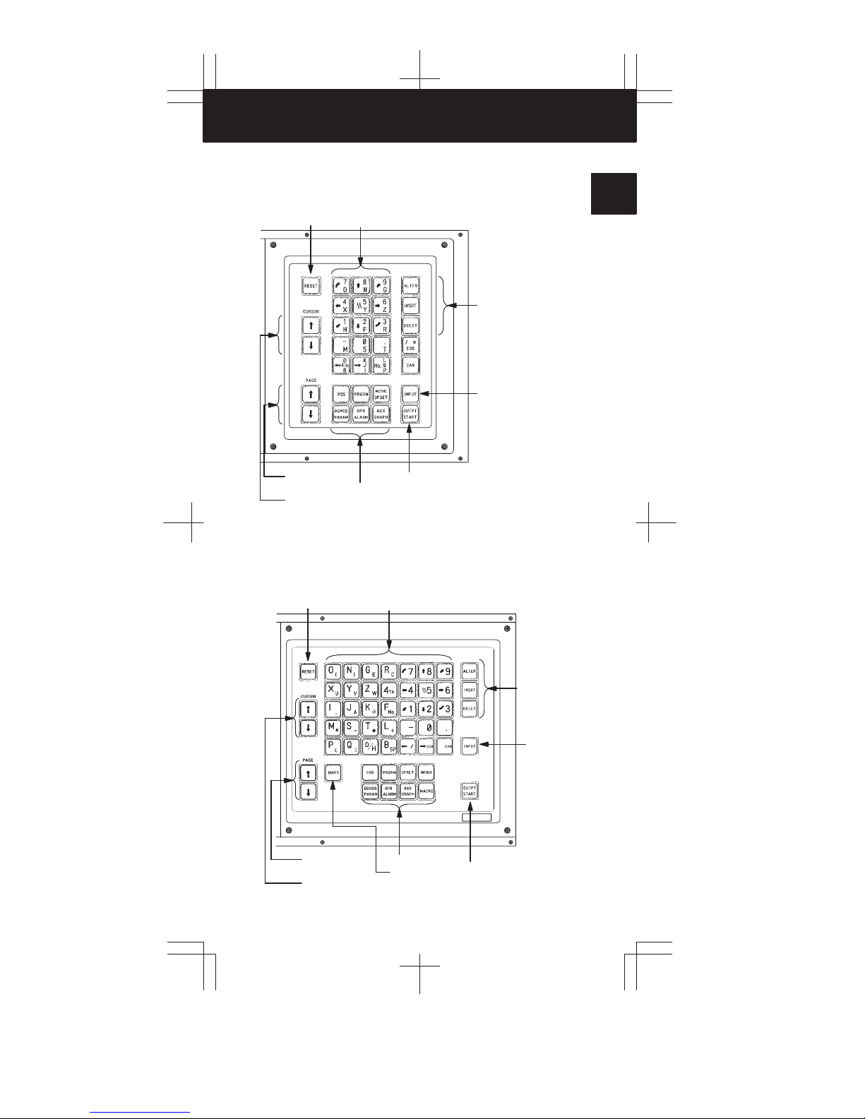
1
Reset button
Page change
keys
Cursor move keys
Reset key
Data input keys
Function keys
Data input keys
Output/Start key
Program edit keys
Input key
2
3
4
5
6
7
Page change
keys
Cursor move keys
Function keys
Shift key
Program edit
keys
Output/Start key
8
9
Input key
10
2
Page 4

1. CRT/MDI PANEL
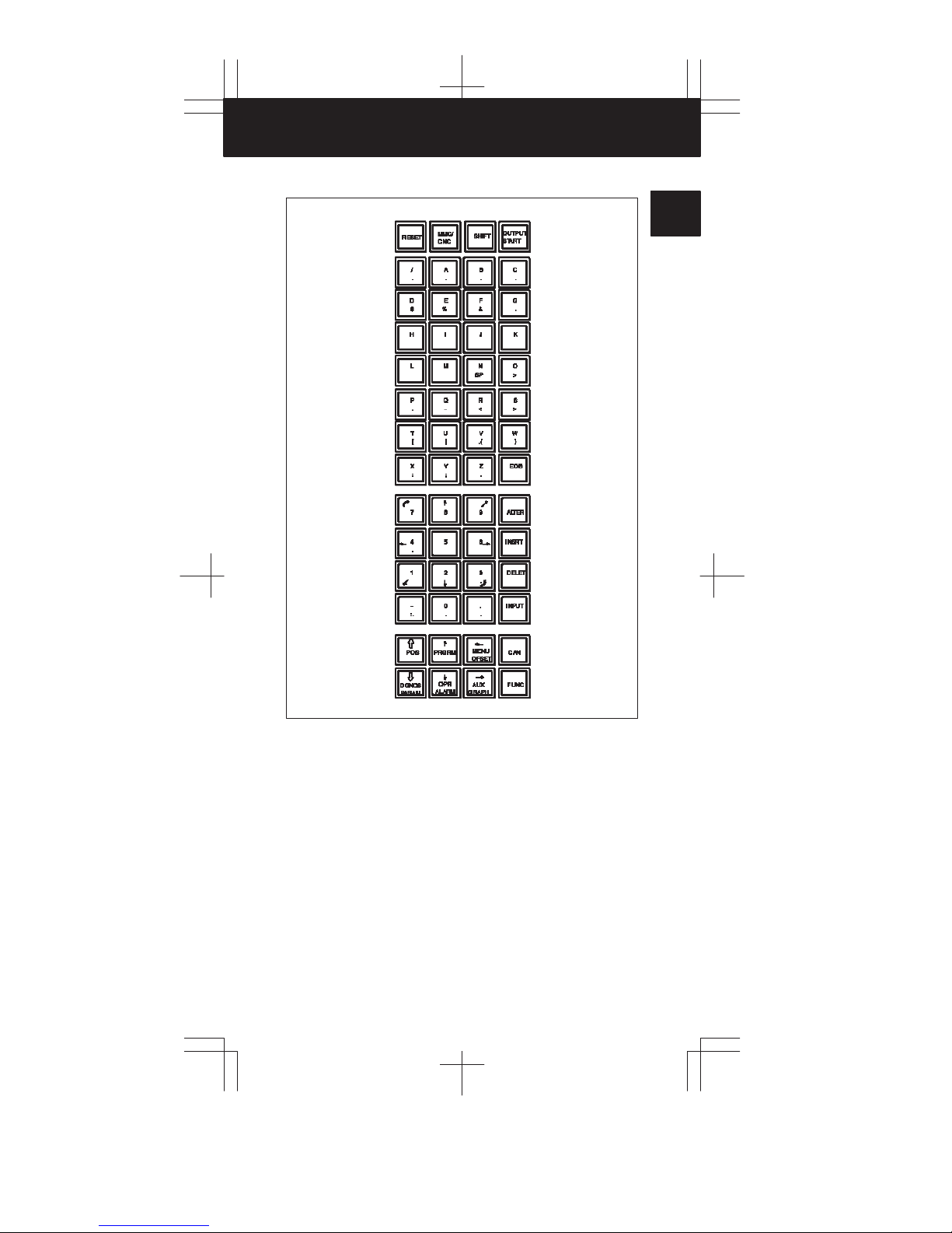
1.3 CRT/MDI with MMC
POWER
I+OFF O+OFF
3
Page 5

MMC/CNC change key
Shift keyReset key
RESET
/.A.B.C
D$E%F&G
H
L M NSPO
P
.Q–R<S>
T
[U]V.{W}
X
:Y;Z.
7 8 9 ALTER
4.5 6 INSRT
1 2 3
–
:.0...
POS PRGRM CAN
DGNOS
PARAM
CNC
I J K
MENU
OFSET
OPR
AUX
ALARM
GRAPH
START
.
.
>
EOB
DELET
.
INPUT
FUNC
OUTPUT
MMC/
SHIFT
Function keys
Start/output key
Program edit keys
Input key
1
2
3
4
5
6
7
8
9
10
4
Page 6
1. CRT/MDI PANEL
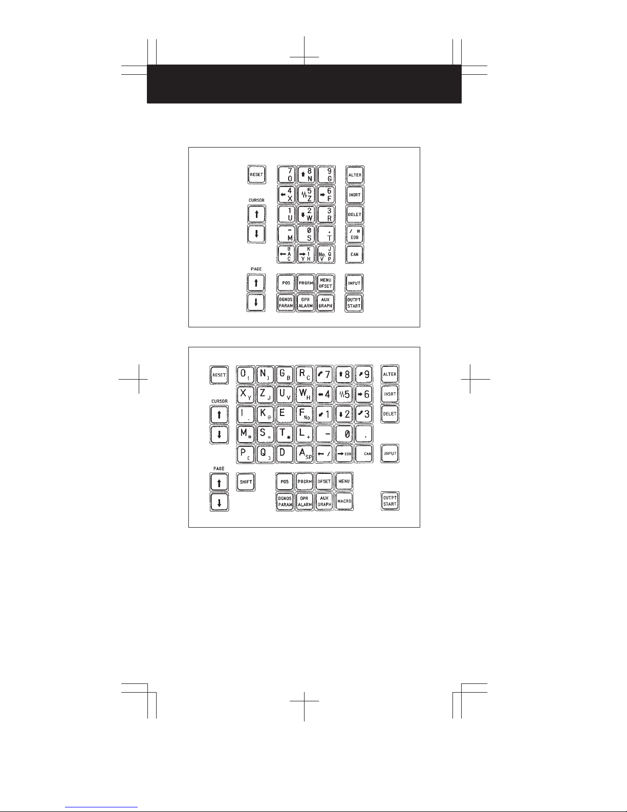
1.4 MDI Keyboard
Standard MDI keyboards (T series)
Full MDI keyboards (T series)
5
Page 7

Standard MDI keyboards (M series)
1
2
3
4
Full MDI keyboards (M series)
5
6
7
8
9
10
6
Page 8

1. CRT/MDI PANEL
Full MDI keyboards (14″ CRT for M series)
7
Page 9
MDI keyboards with MMC
1
2
3
4
5
6
7
8
9
10
8
Page 10
1. CRT/MDI PANEL
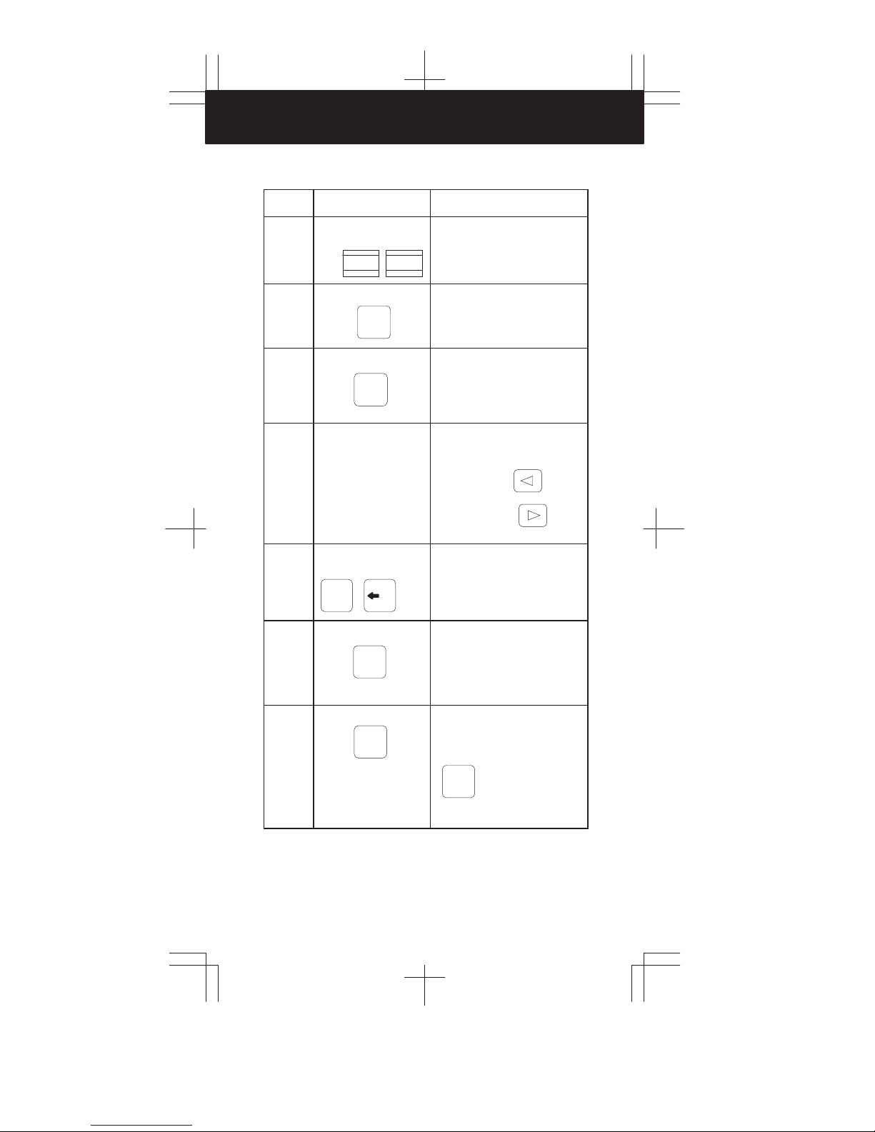
1.5 Explanation of the Keyboard
Number Name Explanation
1 Power ON and OFF buttons
f OFF | ON
Press these buttons to turn CNC power
ON and OFF.
2 RESET key
RESET
3 START key
OUTPT
START
4 Soft keys (option) The soft keys have various functions,
5 Address and numeric keys
N
6 SHIFT key
SHIFT key
(Full MDI keyboard)
7 INPUT key
4
(
SHIFT
INPUT
Press this key to reset the CNC, to cancel an alarm, etc.
This key is used to start MDI operation
or automatic operation, depending on
the machine. Refer to the manual provided by the machine tool builder. This
key is also used to output data to an input/output device.
according to the applications. The soft
key functions are displayed at the bottom of the CRT screen.
Soft key of left edge :
Soft key of right edge :
Continuous menu key
Press these keys to input alphabetic,
numeric, and other characters.
…
Some keys have two characters on
their keytop. Pressing the <SHIFT>
key switches the characters. Special
character is displayed on the screen
when a character indicated at the bottom right corner on the keytop can be
entered.
When an address or a numerical key is
pressed, the data is input to the buffer,
and it is displayed on the CRT screen.
To copy the data in the key input buffer
to the offset register, etc., press the
key.
INPUT
Return menu key
9
This key is also used to input data from
an input/output device.
Page 11
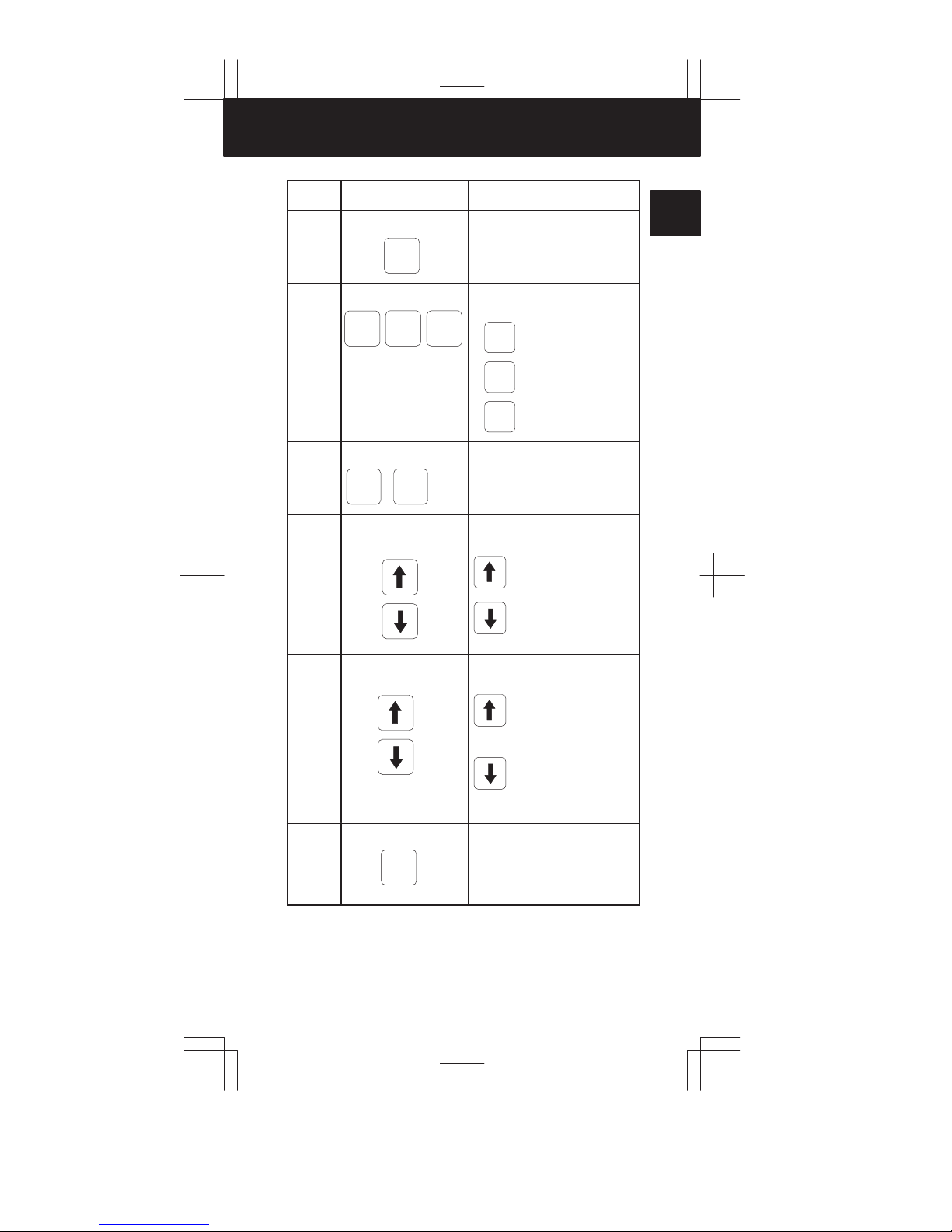
Number ExplanationName
8 Cancel key
CAN
Press this key to delete the input data
or the last character in the key input
buffer.
1
9 Program edit keys
INSRT
ALTER
10 Function keys
POS PRGRM
11 Cursor move keys
DELET
CURSOR
12 Page change keys
PAGE
13 MMC/CNC change key
MMC/
CNC
Press these keys when editing the program.
ALTER
: Alteration
: Insertion
INSRT
DELET
: Deletion
Press these keys to switch display
screens for each function.
…
There are two different cursor move
keys.
: This key is used to move
the cursor in an upward or
reverse direction.
: This key is used to move
the cursor in a downward
or forward direction.
Two kinds of page change keys are
available.
: This key is used to
changeover the page on
the CRT screen in the reverse direction.
: This key is used to
changeover the page on
the CRT screen in the forward direction.
Selects whether the MMC screen or
CNC screen is displayed on the CRT.
2
3
4
5
6
7
8
9
10
10
Page 12

1. CRT/MDI PANEL
1.6 Key Input
For standard MDI keyboard
On the standard MDI keyboard, the same key is used to input both an
address and a numeric value.
When “ADRS.” is displayed on the top of the key input buffer , addresses can
be input.
When “NUM.” is displayed on the top of the key input buffer, numeric values
can be input.
Press
ADRS.
[ ][ ]
4
X
NUM. X
[ ][ ]
key
Press
NUM. X
[ ][ ]
4
X
NUM. X 4
[ ][ ]
key
The following keys are used for inputting multiple addresses. They may be
not displayed on the screen depending on the options used.
T series
B
A
NO.
V
Y
C
K
I
H
J
Q
P
CA B
IKY
H
JQ P
D
L
V
M series
11
D
4th
B
K
J
I
L
P
NO.
Q
D B 4th
IJK
PQL
Page 13

For full MDI keyboard
A “<” is displayed at the end of the key input buffer indicating the input
position of the next character.
1
Key input
buffer
display
T o input the symbol indicated at the lower part of a key top, press the
key to change the prompt < to ƞ. Then press the key.
N001X100Z<
[ ] [ ] [ ] [ ] [ ]
Key input buffer display
2
3
SHIFT
4
5
6
7
8
9
10
12
Page 14
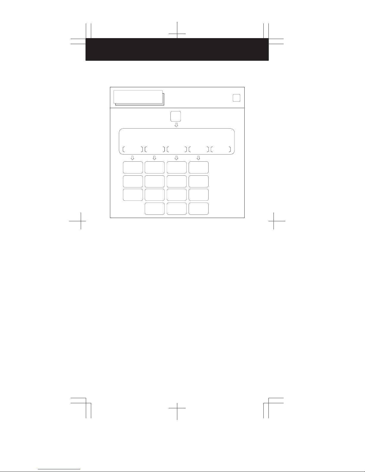
2. CRT/MDI OPERA TION
2.1 Screen Transition Triggered by the Each Function Key
POSITION DISPLAY
SCREEN
Screen transition triggered by the
function key
Current position screen
ABS REL ALL HNDL
Position display
of absolute coordinate system
Display of run
time and parts
count
Display of
actual speed
Position displays
of relative coordinate system
Display of run
time and parts
count
Display of
actual speed
Setting of relative coordinate
values
Total position
display of each
coordinate
system
Display of run
time and parts
count
Display of
actual speed
Display of
distance to go
POS
Manual handle
interruption
Display of run
time and parts
count
Display of
actual speed
Display of
distance to go
POS
13
Page 15

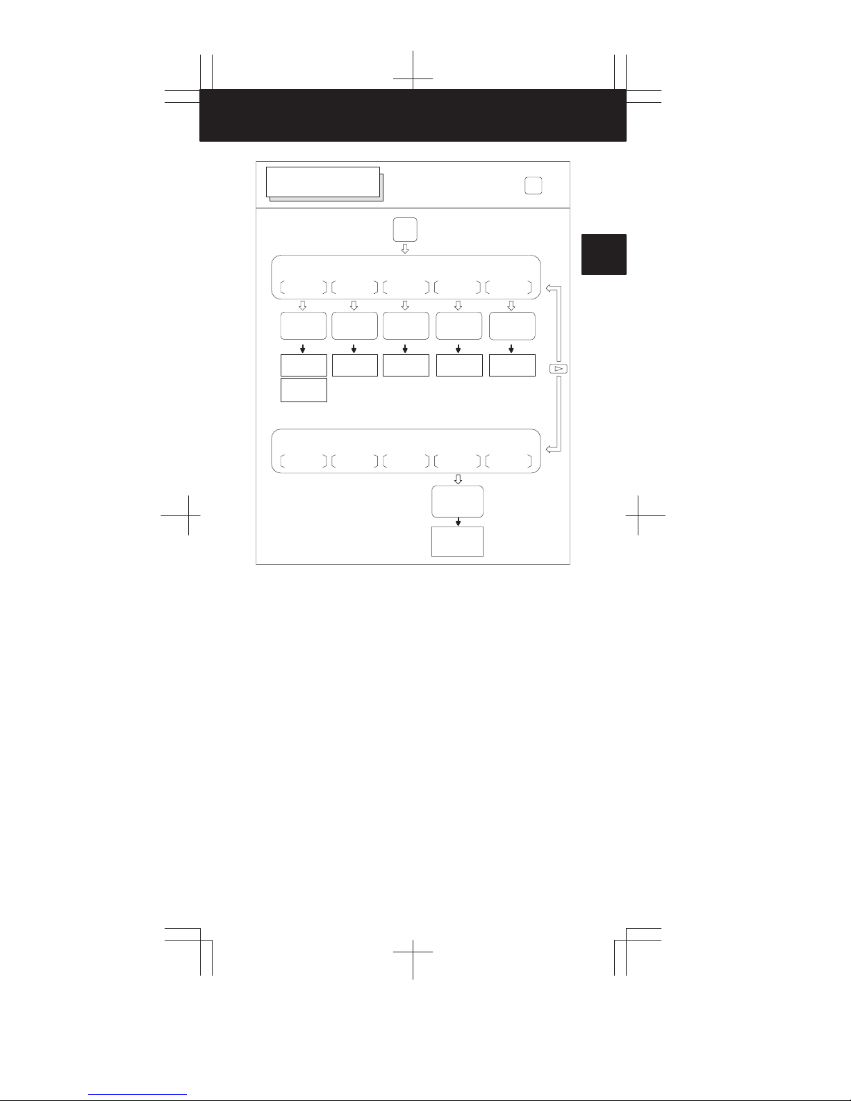
PROGRAM SCREEN
PRGRM
PRGRM
1
Program screen
PRGRM
Display of program contents
Display of program number
and sequence
number
Program screen
BG–EDT
Back ground
editing
screen
CURRNT NEXT
Display of current block and
modal data
Program being
executed
Absolute / relative
coordinate value
Distance to go
Modal values
*1
*2
FL.SDL
Setting of
schedule
Display of current block and
next block
Command
for MDI operation
Displayed in MDI mode
Not displayed in MDI mode
*2
[SCHDUL]
AUTO (MDI)
CHECK
*1
(MDI)
*1
AUTO
2
*1
RSTR
3
Program restart
4
5
6
7
8
9
10
14
Page 16

2. CRT/MDI OPERA TION
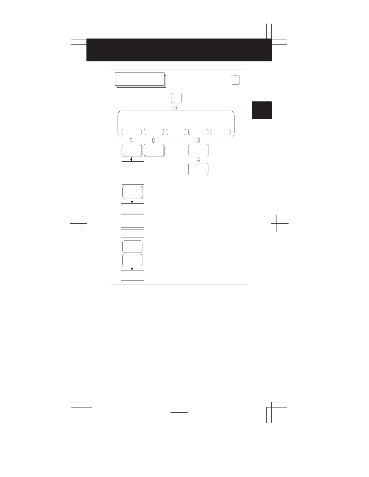
PROGRAM SCREEN
PRGRM
Program screen
*1
FLOPPY
PRGRM
Program editing screen
LIB C.A.P.
Display of program directory
on CNC
memory
Condense of
CNC memory
*1
Displayed if the Floppy Cassette is specified as the input/output unit
*2
Displayed if the above conditions are not satisfied
I/O
Display of program directory
on floppy cassette
EDIT
*2
*1
Program screen
EDIT
BG–EDT EX–EDT
Back ground
editing screen
Conversational
programming
screen
Extended part
program editing
PRGRM
15
Page 17
OFFSET SCREEN
Tool offset value
OFFSET
MACRO
Screen transition triggered by
the function key
(M series)
MENU
OFSET
MENU
WORK
TOOLLF
MENU
OFSET
1
2
Display of tool
offset value
Setting of tool
offset value
Tool length
measurement
Tool offset value
Display of
custom macro
variables
Setting of macro
variables
Display of pattern menu
Setting of pattern data
Display of workpiece zero point
offset value
Setting of workpiece zero point
offset value
WORK48
Display of the additional workpiece
zero point offset
value
Setting of the additional workpiece
zero point offset
value
Display of tool
life management data
Preset of tool
life counter
3
4
5
6
7
8
9
10
16
Page 18

2. CRT/MDI OPERA TION
OFFSET SCREEN
Tool offset value
WEAR
OFFSET
Display tool
wear offset
value
Set tool wear
offset value
Tool length
measurement
Tool offset value
TOOLLF
Display tool
life management data
Preset tool life
management
data
GEOM
Display tool
geometry offset value
Set tool geometry offset value
WEAR
Display Y–axis
tool wear offset value
Set Y–axis tool
wear offset
value
Screen transition triggered by
the function key (T series)
MENU
OFSET
W.SHFT
WORK
Display work
shift or workpiece zero point
offset value
Set work shift
or workpiece
zero point offset value
MACRO
Display macro
variables
Set macro variables
GEOM
Display Y–axis
tool geometry
offset value
Set Y–axis tool
geometry offset value
MENU
OFSET
17
Page 19
PARAMETER/DIAGNOSTIC SCREEN
DGNOS
PARAM
DGNOS
PARAM
1
Parameter screen
PARAM DGNOS
Display of parameter
screen
Setting of parameter
Setting of pitch
error compensation data
Display of
setting data
Setting of setting data
Setting of sequence number
comparison and
stop
Setting of parts
count
Display of run
time, parts count
Display of date
and clock
Setting of date
and clock
Display of
diagnosis
screen
*
SV–PRM
Display of
servo setting
screen
Display of
servo tuning
screen
*
The servo setting/tuning screen can be suppressed if bit 0 of
parameter 0389 is specified accordingly.
2
3
4
5
6
7
8
9
10
18
Page 20

2. CRT/MDI OPERA TION
ALARM SCREEN
Alarm screen
ALARM
Display of
alarm screen
OPR MSG
Display of software operator’s
panel general
purpose switch
Setting of software
operator’s panel
general purpose
switch
Screen transition triggered
by the function key
OPR
ALARM
Display of operator’s message
OPR
ALARM
19
Page 21

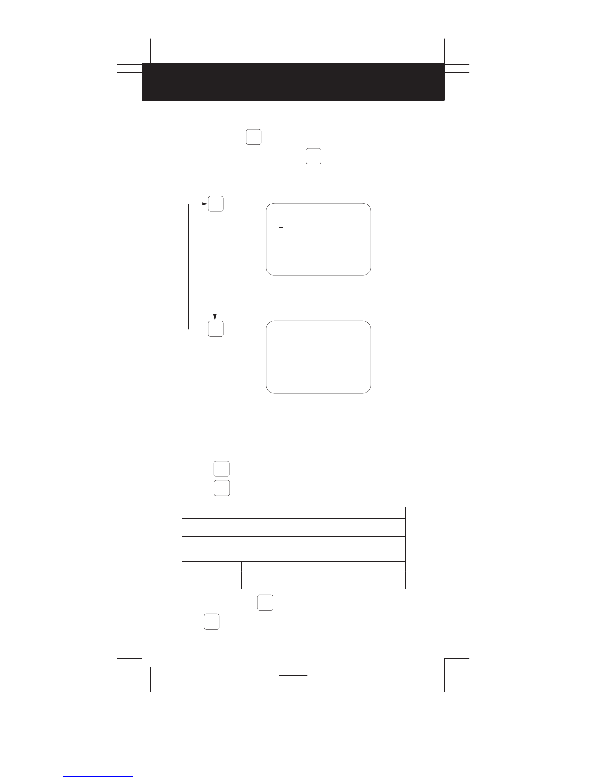
2.2 CRT/MDI Operation
Command display
Function button
PRGRM
1
During the AUTO mode, press (page) or the corresponding soft
key to cause any of the following four types of displays to appear.
(1) A program being currently executed is displayed.
PRGRM
PAGE
PROGRAM O2000 N0130
O2000 ;
N100 G92 X0 Y0 Z50. ;
N110 G91 G00 Y50. ;
N120 Z–50. ;
130 G41 G17 H1 G01 X20. F3000 ;
N
N140 G02 J–25.5 ;
N150 X20. ;
N160 G02 X12.5 Y12.5 R12.5 ;
N170 G01 Y40. ;
N180 X30. Y30. ;
N190 G40 X50. ;
16:59:40 BUF AUTO
[ PRGRM ] [CURRNT] [ NEXT ] [ CHECK ] [ RSTR ]
S 0 T
The cursor is set to the beginning of the program
being executed.
PAGE
PAGE
(2) The command currently being executed and the
modal values specified before are displayed.
PROGRAM O2000 N00130
(CURRNT) (MODAL)
X 20.000 G67 G01 F 3000
G01 F 3000 G54 G17 R
G17 H 1 G64 G91 P
G41 G49 T
G80 G98 S
02:50:52 BUF AUTO
[ PRGRM ] [ CURRNT ] [ NEXT ] [ CHECK ] [ RSTR ]
G69 G22 Q
G15 G94 H
G25 G21 M
G41 S
G80
G50
S 0 T0000
(3) The command currently being executed and the
next command to be executed are displayed.
PROGRAM O2000 N0130
(CURRNT) (NEXT)
X 20.000 J –25.500
G01 F 3000 G02
G17 H 1
G41
G80 G80
S 0 T
02:52:14 BUF AUTO
[ PRGRM ] [ CURRNT ] [ NEXT ] [ CHECK ] [ RSTR ]
PAGE
(4) Program check
The block currently being executed, the current
position, and the modal values specified before
are displayed.
PROGRAM CHECK O2000 N0130
N130 G41 G17 H1 G01 X20. F3000 ;
N140 G02 J–25.5 ;
N150 X20.0 ;
N160 G02 X12.5 Y12.5 R12.5 ;
(RELATIVE) (DIST TO GO) ( G)
X 17.600 X 2.400 G01 G21 G50
Y 50.000 Y 0.000 G17 G41 G67
Z 0.000 Z 0.000 G91 G49 G54
F 3000 P H 1 S
R Q M T
ACT.F 3000 MM/M S 0 T
02:53:16 BUF AUTO
[ PRGRM ] [ CURRNT ] [ NEXT ] [ CHECK ] [ RSTR ]
G22 G80 G64
G94 G98 G69
* Besides the above displays, the program restart screen is displayed in
some cases. (Option)
20
2
3
4
5
6
7
8
9
10
Page 22
2. CRT/MDI OPERA TION
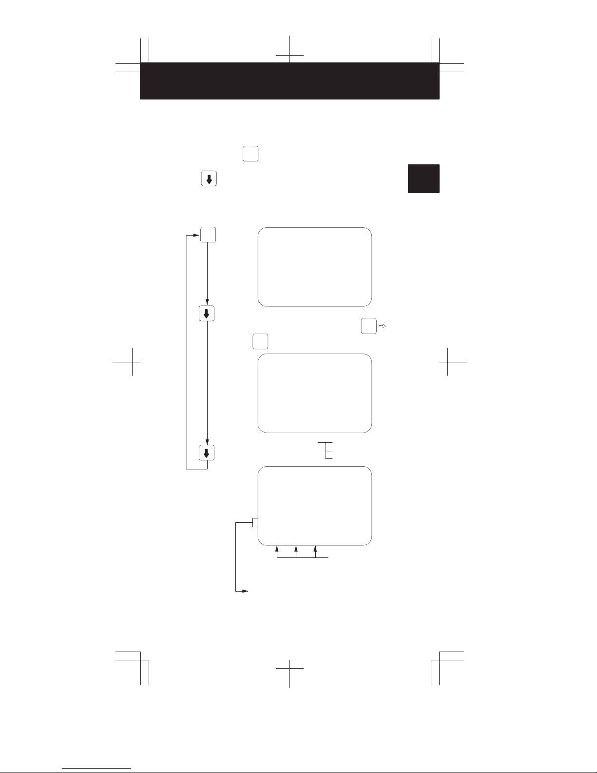
Program display
Function button
During the EDIT mode, press the
PRGRM
PRGRM
key several times or the
corresponding soft key to cause either of the following two types of
displays to appear.
(1) The program is displayed.
PRGRM
PROGRM
O0100 ;
N10 G92 X0 Y0 Z0 ;
N20 G00 Z10. Y–50. ;
N30 G
01 X200. Y–60. F500 T12 ;
N40
%
< S 0 T
10:39:27 EDIT
[ PRGRM ] [ LIB ] [ FLOPPY ] [ ] [ C.A.P. ]
O0100 N0040
The program and sequence numbers are displayed at
the upper right section of the screen.
(2) The amount of program memory in use is
displayed.
PRGRM
PROGRAM O1224 N0000
SYSTEM EDITION 0466 – 25
PROGRAM NO. USED : 14 FREE : 49
MEMORY AREA USED : 275 FREE : 3820
PROGRAM LIBRARY LIST
O0010 O2000 O0020 O0030 O0200 O0300
O0555 O1200 O0777 O1234 O0040 O0050
O1969 O1224
> S 0 T
03:04:17
[ PRGRM ] [ CONDNS ] [ ] [ ] [ C.A.P. ]
Number of registered programs
Memory area in use
Program list
* If the directory display of floppy cassette is provided, a file list, in addition
to the above displays, appears on the screen.
Reset
Press the
RESET
. This key is usually used to reset the alarm.
When the
A tool movement command continues to be executed.
An M, S, or T continues to be sent
out.
When the buffer is
loaded with one
block
In any case, pressing the
mode,
21
RESET
is pressed, the NC enters one of the states listed below.
Before a reset
The tool decelerates and stops. The unexecuted amount of movement disappears.
A send–out sequence is terminated. Refer
to the machine tool builder’s manual for what
occurs on the machine side.
After a reset
MDI mode The contents of the buffer are not erased.
Other modes The contents of the buffer are erased. The
RESET
causes the labels to be skipped.
BUF display disappears.
RESET
resets the NC. In a mode other than the MDI
Page 23

Custom macro variable display/setting
MENU
Function button
Press the
select the desired screen.
MENU
OFSET
OFSET
MENU
OFSET
key several times or the corresponding soft key to
MENU
OFSET
PAGE
VARIABLE O1234 N1234
NO. DATA NO. DATA
100 123.456 108
101 0.000 109
102 110
103 111
104 112
105 113
106 114
107 115
ACTUAL POSITION (RELATIVE)
X 0.000 Y 0.000
Z 0.000 B 0.000
[OFFSET ] [ MACRO ] [ MENU ] [ WORK ] [ ]
1
2
3
MDI
CURSOR
If a variable is null, the corresponding value
field is left blank. If the absolute value is
greater than 99999999, the corresponding
value field contains ********.
Numeral
INPUT
Tool compensation value display/setting
MENU
OFSET
MENU
OFSET
PAGE
CURSOR
OFFSET O1224 N0000
NO. DATA NO. DATA
001 009 0.000
002 0.000 010 12.269
003 5.000 011 10.230
004 0.000 012 –11.265
005 12.580 013 –8.562
006 0.000 014 0.000
007 0.000 015 0.000
008 0.000 016 0.000
ACTUAL POSITION (RELATIVE)
X 0.000 Y 0.000
Z 0.000
NO. 013 = S 0 T
03:22:13 MDI
[ OFFSET ] [ MACRO ] [ MENU ] [ WORK ] [ TOOLLF ]
Move the cursor to the target offset
number using the cursor keys. Or
press the keys as shown below:
No.
Offset number
4
5
6
7
8
9
INPUT
10
Offset amount
INPUT
22
Page 24

2. CRT/MDI OPERA TION
Alarm display
ALARM MESSAGE O0000 N0000
100P/S ALARM
417SERVO ALARM : X AXIS DGTL PARAM
427SERVO ALARM : Y AXIS DGTL PARAM
OPR
ALARM
NOT READY ALARM MDI
[ ALARM ] [ OPR ] [ MSG ] [ ] [ ]
Software operator’s panel display/setting
OPR
ALARM
Set
4th
B
OPR
key several times or the corresponding soft key to select
ALARM
OPR
ALARM
PAGE
PAGE
K
J
or
I
OPERATOR’S PANEL O1224 N0000
MODE : MDI AUTO EDIT HNDL JOG ZRN
HANDLE AXIS : HX HY HZ
HANDLE MULT. : *1 *10 *100
RAPID OVRD. : 100% 50% 25% F0
JOG FEED : 500 MM/MIN
FEED OVRD. : 100%
ACTUAL POSITION (ABSOLUTE)
X 0.000 Y 0.000
Z 0.000
03:59:30 MDI
[ ALARM ] [ OPR ] [ MSG ] [ ] [ ]
OPERATOR’S PANEL O1224 N0000
BLOCK SKIP : JOFF ON
SINGLE BLOCK : OFF JON
MACHINE LOCK : OFF JON
DRY RUN : OFF JON
PROTECT KEY : PROTECT JRELEASE
FEED HOLD : JOFF ON
ACTUAL POSITION (ABSOLUTE)
X 0.000 Y 0.000
Z 0.000
04:00:18 MDI
[ ALARM ] [ OPR ] [ MSG ] [ ] [ ]
**************
Press the
the target screen.
CURSORorCURSOR
S 0 T
******
S0 T
S 0 T
The switches and controls on the CRT/MDI panel can be used in place of the
counterparts on the machine operator’s panel. (F ANUC MPC is required.)
D Use the buttons shown below for jog feed operations.
23
8
N
5
4
Y
X
1
H
2
F
9
G
6
Z
Page 25

2.3 CRT/MDI Operation and Display (M Series)
Current position display
Function button
POS
1
Press (page) or the corresponding soft key to cause any of the
following three types of displays to appear.
(1) Absolute coordinates
Distance from the programmed zero point
POS
ACTUAL POSITION (ABSOLUTE)
O0010 N0000
X 123.456
Y 363.233
Z 0.000
RUN TIME 0H 1M CYCLE TIME 0H 1M33S
ACT.F 3000 MM/M S 0 T
01:35:22 BUF AUTO
[ ABS ] [ REL ] [ ALL ] [ HNDL ] [ ]
PART COUNT 1
(2) Relative coordinates
Any tool position can be set to 0 by
CAN
. This holds true also of Y and Z.
ACTUAL POSITION (RELATIVE)
O0010 N0000
X 123.456
Y 363.233
Z 0.000
RUN TIME 0H 1M CYCLE TIME 0H 1M33S
ACT.F 3000 MM/M S 0 T
01:36:12 BUF AUTO
[ ABS ] [ REL ] [ ALL ] [ HNDL ] [ ]
(3) General coordinates
ACTUAL POSITION O1000 N00010
(RELATIVE)
X 246.912
Y 913.780
Z 1578.246
(MACHINE)
X 0.000
Y 0.000
Z 0.000
RUN TIME 0H 4M CYCLE TIME 0H 1M38S
ACT.F 0 MM/M S 0 T
01:54:57 MDI
[ ABS ] [ REL ] [ ALL ] [ HNDL ] [ ]
PART COUNT 1
Absolute coordinates
(ABSOLUTE)
X 123.456
Y 456.890
Z 789.123
(DISTANCE TO GO)
X 0.000
Y 0.000
Z 0.000
PART COUNT 1
X
Relative coordinates
Machine coordinates
2
3
4
5
6
7
8
9
The target screen can
be selected directly
by the corresponding
soft key.
The operating time and parts count are displayed.
Two types of operating time and parts count are
displayed on the coordinate display screen.
(position)
10
24
Page 26

2. CRT/MDI OPERA TION
Setting data display/setting
Function button
DGNOS
PARAM
(Parameter pages 1 and 2 are the setting data screens.)
When the title parameter is not on the screen,
press the key or
DGNOS
PARAM
the corresponding soft
key to select the parameter screen.
[Setting]
MDI mode
CURSORorCURSOR
Numeral
INPUT
Display
Item
REVX X–axis mirror image OFF X–axis mirror image ON
REVY Y–axis mirror image OFF Y–axis mirror image ON
TVON No TV check is made. A TV check is made.
ISO EIA code output
INCH Metric input Inch input
I/O (Note) Reader/punch interface channel is selected.
ABS Incremental command (MDI
SEQ Sequence numbers are not in-
PWE Parameter writing is disabled. Parameter writing is enabled.
REV4 Fourth–axis mirror image OFF Fourth–axis mirror image ON
TAPEF F10/11 table format is not used F10/11 table format is used
(during punch)
mode)
serted automatically when a
program is entered from the
MDI.
PARAMETER O1224 N0000
(SETTING 1)
_REVX = 0
REVY = 0
TVON = 0
ISO = 0 (0:EIA 1:ISO)
INCH = 0 (0:MM 1:INCH)
I/O = 0
ABS = 0 (0:INC 1:ABS)
SEQ = 0
NO. REVX = S 0 T
03:30:09 MDI
[ PARAM ] [ DGNOS ] [ ] [ SV–PRM ] [ ]
CLOCK 10/01/10
03:30:18
(page)
PARAMETER O1224 N0000
(SETTING 2)
_PWE = 1 (0:DISABLE 1:ENABLE)
REV4 = 0
TAPEF = 0
(SEQUENCE STOP)
PRGNO = 0
SEQNO = 0
PART TOTA L = 17
PART REQUIRED = 50
PART COUNT = 17
RUN TIME OH 4M CYCLE TIME OH OM 2S
NO. PWE = S 0 T
03:35:07 MDI
[ PARAM ] [ DGNOS ] [ ] [ SV–PRM ] [ ]
0 1
ISO code output
(during punch)
Absolute command (MDI
mode)
Sequence numbers are inserted automatically when a
program is entered from the
MDI.
NOTE See Page 33 for details.
25
Page 27
2.4 CRT/MDI Operation and Display (T Series)
Current position display
Function button POS
1
Press (page) or the corresponding soft key to cause any of the
following three types of displays to appear.
(1) Absolute coordinates
Distance from the programmed zero point
POS
ACTUAL POSITION (ABSOLUTE)
X 200.000
Z 220.000
C 0.000
Y 0.000
RUN TIME 2H47M CYCLE TIME 0H 1M47S
ACT.F 3000 MM/M S 0 T0101
16:14:02 BUF AUTO
[ ABS ] [ REL ] [ ALL ] [ HNDL ] [ ]
PART COUNT 1786
(2) Relative coordinates
Any tool position can be set to 0 by
CAN . This holds true also of Z and Y.
ACTUAL POSITION (RELATIVE)
O0001 N0023
X 200.000
Z 220.000
C 0.000
Y 0.000
PART COUNT 23
RUNTIME 3H30M CYCLE TIME 0H 2M14S
ACT.F 3000 MM/M S 0 T0101
20:03:21 AUTO
[ ABS ] [ REL ] [ ALL ] [ HNDL ] [ ]
(3) General coordinates
ACTUAL POSITION O0100 N0000
(RELATIVE) (ABSOLUTE)
U 0.000 X 200.179
W 0.000 Z 220.000
H 0.000 C 0.000
V 0.000 Y 0.000
(MACHINE) (DISTANCE TO GO)
X –118.170 X 0.000
Z –21.470 Z 0.000
C 0.676 C 0.000
Y 0.046 Y 0.000
RUN TIME 3H30M CYCLE TIME 0H 2M14S
ACT.F 0 MM/M S 0 T0101
20:04:37 AUTO
[ ABS ] [ REL ] [ ALL ] [ HNDL ] [ ]
PART COUNT 23
Absolute coordinates
X
Relative coordinates
Machine coordinates
2
3
4
5
6
7
8
9
10
The target screen can
be selected directly
by the corresponding
soft key.
The operating time and part count are displayed.
Two types of operating time and parts count are
displayed on the coordinate display screen
(position).
26
Page 28

2. CRT/MDI OPERA TION
Setting data display/setting
Function button
DGNOS
PARAM
(Parameter pages 1 and 2 are the setting data screens.)
When the title “parameter” is not on the screen,
press the key or
DGNOS
PARAM
the corresponding soft
key to select the parameter screen.
[Setting]
MDI mode
CURSORorCURSOR
Numeral
INPUT
Display
Item
TVON No TV check is made. A TV check is made.
ISO EIA code output
INCH Metric input Inch input
I/O (Note) Reader/punch interface channel is selected.
SEQ Sequence numbers are not in-
PWE Parameter writing is disabled. Parameter writing is enabled.
TAPEF F10/11 table format is not used. F10/11 table format is used.
(during punch)
serted automatically when a
program is entered from the
MDI.
PARAMETER O0001 N0001
(SETTING 1)
TVON = 1
ISO = 1 (0:EIA 1:ISO )
INCH = 0 (0:MM 1:INCH)
I/O = 0
SEQ = 1
CLOCK 94/05/16
NO. TVON S 0 T0101
21:35:25 MDI
[ PARAM ] [ DGNOS ] [ ] [SV–PRM ] [ ]
12:11:52
(page)
PARAMETER O0001 N0001
(SETTING 2)
_PWE = 0 (0:DISABLE 1:ENABLE)
TAPEF = 0
(SEQUENCE STOP)
PRGNO = 0
SEQNO = 0
PART TOTA L = 2 3
PART REQUIRED = 0
PART COUNT = 23
RUN TIME 3H36M CYCLE TOME 0H 0M 0S
NO. PWE S 0 T0101
21:36:25 MDI
[ PARAM ] [ DGNOS ] [ ] [SV–PRM ] [ ]
0 1
ISO code output
(during punch)
Sequence numbers are inserted automatically when a
program is entered from the
MDI.
NOTE See Page 33 for details.
27
Page 29

2.5 CRT/MDI Operation and Display (with MMC)
(1) Operation
Key operation can only be done when the CNC screen is displayed on
the CRT display of the CRT/MDI panel. Address keys and numerical
keys are independently arranged on 00–C. However, inputting data is
exactly the same as that of 0–C. The page key
, and selection key on the software operator’s
panel are of combined use with the function key. Press the
corresponding key for use as a page key , cursor key , and selection key
on the software operator’s panel. Press the corresponding key while
pressing the “FUNC” key as the function key.
Five keys on the right half ten keys are effective for the variable section,
and the other five keys on the left half are effective for selecting position
display data in the fixed section.
When the number is specified by a method like the parameter screen,
because there is no NO. key use the cursor key
(2) Display
MMC/
Press
key on the CRT/MDI panel to display the CNC screen
CNC
when the MMC screen is displayed on the CRT display of the CRT/MDI
panel.
The CNC screen consists of a variable section and a fixed section. The
variable section is the part that is surrounded by the frame at the bottom
right, and its display contents are the same as displayed on the 9” CRT
display of 0–C. Therefore, the screen selected by function key, page
key, cursor key, and soft key is displayed.
The fixed section is the rest of the above variable section, and its display
contents are position data, operation time (optional), modal data, and
S, T command value, as shown on the screen. Display items of this
section cannot be changed by the screen selection operation. However,
its display contents are always renewed.
, cursor key
instead.
1
2
3
4
5
6
7
Fixed section
ACTUAL POSITION (ABSOLUTE)
X 0.000 O0009
Y 0.000
Z 0.000 N0009
(MODAL)
G64 G00 F
G17 R
G91 P
G22 Q
G94 H
G21 M
G40 S
G49 T
G80
G98
G67
G54
RELABS ALL
PARAMETER
NO. DATA NO. DATA
0001 10000100 0011 00000000
0002 00000011 0012 00000001
0003 00000000 0013 10000000
0004 01110111 0014 00000000
0005 01110111 0015 00000000
0006 01110111 0016 00000000
0007 01110111 0017 01111111
0008 00000011 0018 00000000
0009 01000100 0019 00000000
0010 11000100 0020 00000000
NO. 0001 =
PRGRM
PART COUNT 0
RUN TIME 29H 47M
CYCLE TIME 0H 0M 0S
DGNOS
8
9
Variable
section
10
MDI
+
28
Page 30

2. CRT/MDI OPERA TION
2.6 Data Input/Output (FANUC Cassette)
Setting the beginning of the file
1 Select the EDIT mode
2 Press the
times to select the program list
screen.
3 Key in address N.
4 Key in the target file number.
CNC parameter output
1 Select the EDIT mode
2 Press the
times to select the parameter
screen.
PRGRM
key several
PROGRAM O1224 N0000
SYSTEM EDITION 0466 – 25
PROGRAM NO. USED : 14 FREE : 49
MEMORY AREA USED : 275 FREE : 3820
PROGRAM LIBRARY LIST
O0010 O2000 O0020 O0030 O0200 O0300
O0555 O1200 O0777 O1234 O0040 O0050
O1969 O1224
> S 0 T
03:04:17
[ PRGRM ] [ CONDNS ] [ ] [ ] [ C.A.P. ]
N0 ⇒ Locates the beginning of the cassette.
This is used regardless of whether the file is on the floppy
disk.
N1 ⇒ Locates the beginning of the cassette.
This is used when the file is on the floppy disk.
N2 to N9999 ⇒Locates the beginning of any file.
DGNOS
key several
PARAM
PARAMETER O1224 N0000
(SETTING 1)
_REVX= 0
REVY= 0
TVON = 0
ISO = 0 (0:EIA 1:ISO)
INCH = 0 (0:MM 1:INCH)
I/O = 0
ABS = 0 (0:INC 1:ABS)
SEQ = 0
NO. REVX = S 0 T
03:30:09 EDIT
[ PARAM ] [ DGNOS ] [ ] [ SV–PRM ] [ ]
CLOCK 10/01/10
03:30:18
3 Press the
OUTPT
key, and output begins.
START
NOTE Parameter Nos. nine hundreds (900 to 999) are not output.
PMC parameter output
1 Select the EDIT mode.
DGNOS
2 Press the
key several times to select the DGNOS (diagnose)
PARAM
screen.
OUTPT
3 Press the
key, and output begins.
START
29
Page 31

Program output
1 Select the EDIT mode.
2 Press the
PRGRM
key several
times to select the program list
screen.
3 Key in address O.
4 Key in the target program number.
5 Press the
OUTPT
key, and output begins.
START
* All–program output: 0–9999
Offset output
1 Select the EDIT mode.
MENU
OFSET
2 Press the
times to select the offset
screen.
3 Press the
key several
OUTPT
key, and output begins.
START
PROGRAM O1224 N0000
SYSTEM EDITION 0466 – 25
PROGRAM NO. USED : 14 FREE : 49
MEMORY AREA USED : 275 FREE : 3820
PROGRAM LIBRARY LIST
O0010 O2000 O0020 O0030 O0200 O0300
O0555 O1200 O0777 O1234 O0040 O0050
O1969 O1224
> S 0 T
03:04:17
[ PRGRM ] [ CONDNS ] [ ] [ ] [ C.A.P. ]
OUTPT
START
OFFSET O1224 N0000
NO. DATA NO. DATA
001 009 0.000
002 0.000 010 12.269
003 5.000 011 10.230
004 0.000 012 –11.265
005 12.580 013 –8.562
006 0.000 014 0.000
007 0.000 015 0.000
008 0.000 016 0.000
ACTUAL POSITION (RELATIVE)
X 0.000 Y 0.000
Z 0.000
NO. 013 = S 0 T
03:22:13 MDI
[ OFFSET ] [ MACRO ] [ MENU ] [ WORK ] [ TOOLLF ]
1
2
3
4
5
6
7
Conversational mode data output
[M series]
1 Select the EDIT mode.
MENU
OFSET
2 Press the
data screen.
3 Press the
key several times to select the conversational mode
OUTPT
key, and output begins.
START
8
9
10
30
Page 32

2. CRT/MDI OPERA TION
CNC parameter input
1 Set setting data PWE to 1 (page 2 of the parameter screen).
PARAMETER O1224 N0000
(SETTING 2)
_PWE = 1 (0:DISABLE 1:ENABLE)
REV4 = 0
TAPEF = 0
(SEQUENCE STOP)
This is set in the
MDI mode or at an
emergency stop.
PRGNO = 0
SEQNO = 0
PART TOTA L = 17
PART REQUIRED = 50
PART COUNT = 17
RUN TIME OH 4M CYCLE TIME OH OM 2S
NO. PWE = S 0 T
03:35:07 MDI
[ PARAM ] [ DGNOS ] [ ] [ SV–PRM ] [ ]
NOTE Alarm P/S100 occurs at this point. Press the
DGNOS
PARAM
key again to
cause the parameter screen to appear.
2 Select the EDIT mode.
* Release the emergency stop condition.
3 Press the
INPUT
key, and input begins.
* Alarm P/S000 occurs at this point. Turn the CNC power off and on
again.
* If you want to enter parameters during the emergency stop state,
press and hold down the
Key, then press the
EOB
INPUT
Key. In
this case, it is not necessary to select the EDIT mode.
NOTE It is impossible to enter parameter Nos. nine hundreds (900 to 999).
PMC parameter input
1 Select the EDIT mode.
2 Locate the beginning of the file.
3 Disable program protection (KEY=1).
4 Turn to 1 at setting parameter PWE.
DGNOS
5 Press the
key several times to select the DGNOS (diagnose)
PARAM
screen.
INPUT
6 Press the
key, and input begins.
NOTE PWE should be 1 in case of parameter 393#7=0.
Program input
1 Select the EDIT mode.
2 Locate the beginning of the file.
3 Disable program protection (KEY=1).
PRGRM
4 Press the
times to select the program
screen.
key several
PROGRAM O1224 N0000
SYSTEM EDITION 0466 – 25
PROGRAM NO. USED : 14 FREE : 49
MEMORY AREA USED : 275 FREE : 3820
PROGRAM LIBRARY LIST
O0010 O2000 O0020 O0030 O0200 O0300
O0555 O1200 O0777 O1234 O0040 O0050
O1969 O1224
> S 0 T
03:04:17
[ PRGRM ] [ CONDNS ] [ ] [ ] [ C.A.P. ]
31
Page 33

5 Press the
INPUT
key, and input begins.
* When only one program is entered.
6 Key in address O.
7 Key in the target program number.
8 Press the
INPUT
key, and input begins.
Offset input
1 Select the EDIT mode.
2 Locate the beginning of the file.
3 Disable program protection (KEY=1).
MENU
OFSET
4 Press the
times to select the offset
screen.
key several
OFFSET O1224 N0000
NO. DATA NO. DATA
001 009 0.000
002 0.000 010 12.269
003 5.000 011 10.230
004 0.000 012 –11.265
005 12.580 013 –8.562
006 0.000 014 0.000
007 0.000 015 0.000
008 0.000 016 0.000
ACTUAL POSITION (RELATIVE)
X 0.000 Y 0.000
Z 0.000
NO. 013 = S 0 T
03:22:13 MDI
[ OFFSET ] [ MACRO ] [ MENU ] [ WORK ] [ TOOLLF ]
1
2
3
4
5
5 Press the
INPUT
key, and input begins.
Conversational mode data input
[M series]
1 Select the EDIT mode.
2 Locate the beginning of the file.
3 Disable program protection (KEY=1).
PRGRM
4 Press the
5 Key in address 0.
6 Key in any program number.
7 Press the
8 Select the AUTO mode.
9 A program entered before is executed.
* Be cautious about the following parameter.
PRM, No. 015
CAUTION
When a decimal point is omitted from an address in which it can be
used:
1 : mm, inch, and s units (usually)
0 : Least input increment (at data input time)
key several times to select the program list screen.
INPUT
key, and input begins.
Caution
*******
6
7
8
9
10
32
Page 34

2. CRT/MDI OPERA TION
Function
Parameters related to data input/output
To use the FANUC floppy cassette, set the parameters as follows:
Setting: I/O = 0 (Note)
Parameter: ISO = 1
PRM, No. 002
1****0*1
PRM, No. 552
PRM, No. 010
10 (4800BPS)
* * * Note * * * *
NOTE1 1 : Protects program numbers 9000s (9000 to 9999).
0 : Enables editing of program numbers 9000s (9000 to 9999).
PRM, No. 038
0 1 * * Note * * *
NOTE2 1 : A full keyboard is used.
0 : A standard keyboard is used.
NOTE3 I/O = selects a device used for data input/output through a reader/
punch interface.
Related parameter No.
I/O=0 I/O=1 I/O=2 I/O=3
Feed (NFED) 2.7 12.7 50.7 51.7
20 mA current loop
(ASR33)
Stop bit (STP2) 2.0 12.0 50.0 51.0
I/O device model
specification
Baud rate 552 553 250 251
Connector number
2.2 12.2 Unusable
38.7
38.6
M5
Channel 1M5Channel 1
38.7
38.6
38.5
38.4
M74
Channel 2
38.2
38.1
M77/M73
Channel 3
For M77, either RS–232–C or RS–422 can be selected by parameter No.
55.3.
The connector number is M73 when RS–422 is used with an external clock.
33
Page 35

Displaying the directory of floppy disk files
1
Press the EDIT switch on the machine operator’s panel.
2
Press function
3
Press soft key [FLOPPY].
4
Press page key or .
5
The screen below appears.
PRGRM
key .
1
2
DIRECTORY (FLOPPY)
NO. FILE NAME
0001 PARAMETER
0002 ALL. PROGRAM
0003 O0001
0004 O0002
0005 O0003
0006 O0004
0007 O005
0008 O0100
0009 O0555
19:36:51 EDIT
SRHFIL
[][][][][]
6
Press a page key again to display another page of the directory.
READ PUNCH DELETE
O0555 N0000
(METER) VOL
65.6
1.9
1.3
1.3
1.3
1.3
1.3
1.9
1.3
S0 T
Reading files
1
Press soft key [READ] after directry is displayed.
DIRECTORY (FLOPPY)
NO. FILE NAME
READ
_FILE NO. = PROGRAM NO. =
NUM. S 0 T
19:38:35
EXEC
[][][][][]
CAN STOP
O0555 N0000
(METER) VOL
EDIT
3
4
5
6
7
8
9
2
Enter a file number, then press function
3
T o modify the program number , enter the program number , then press
function
4
Press soft key [EXEC].
5
Press soft key [CAN] to return to the soft key display shown in
the screen of directory display.
INPUT
key.
INPUT
key .
10
34
Page 36

2. CRT/MDI OPERA TION
Outputting programs
1
Press soft key [PUNCH] after directry is displayed.
DIRECTORY (FLOPPY)
NO. FILE NAME
PUNCH
_FILE NO. = _ PROGRAM NO. =
NUM. S 0 T
19:39:17
[][][][][]
2
Enter a program number. To write all programs into a single file, enter
PRG–NOEXEC
CAN STOP
O0555 N0000
(METER) VOL
EDIT
–9999 in the program number field. In this case, the file name
“ALL.PROGRAM” is registered.
Then press function
3
Press soft key [EXEC].
4
Press soft key [CAN] to return to the soft key display shown in
INPUT
key.
the screen of directry display.
Deleting files
1
Press soft key [DELETE] after directry is displayed.
DIRECTORY (FLOPPY)
NO. FILE NAME
O0555 N0000
(METER) VOL
DELETE
_FILE NO. =
NUM. S 0 T
19:39:56
EXEC
[][][][][]
2
Specify the file to be deleted.
CAN STOP
EDIT
When specifying the file with a file number, type the number and
press function
3
Press soft key [EXEC].
4
Press soft key [CAN] to return to the soft key display shown in
INPUT
key.
the screen of directry display.
35
Page 37

Procedure for changing the file name
1
Press soft key [RENAME] after directry is displayed.
2
Position the cursor to FILE NO. then enter the number of the file whose
name is to be changed. Press the
3
Position the cursor to NAME and key in a new file name. Then, press
INPUT
the
4
Press soft key [EXEC].
5
To return to the previous screen, press the [CAN] soft key.
FILE DIRECTORY
NO. FILE NAME
0001 PARAMETER 87.1
0002 ALL.PROGRAM 87.1
0003 O0001 1.9
0004 O0021 7.1
0005 O0041 7.1
0006 O0615 5.8
0007 O0651 9.1
0008 O0601 7.1
0009 O0645 5.8
RENAME
[][][][][]
key.
FILE NO. = NAME=
NUM. S 0 T0101
21:59:53 EDIT
EXEC
CAN STOP
INPUT
key.
O0001 N0000
(METER) VOL
1
2
3
4
5
6
36
7
8
9
10
Page 38

3. OPERATION LIST
Reset
Classifi-
cation
Registration
from MDI
Registration
from NC
tape
SET-
KEY
Function
Resetting of operating time
Resetting of number of machined parts
Resetting of OT alarm At power–up
Resetting of alarm 100 —
Parameter input f MDI mode
Offset input —
Setting data input MDI mode
PMC parameter input
Tool length measurement JOG mode
Parameter input (NC tape
→ memory)
PMC parameter input
Offset input EDIT mode
Program registration f
SW
f
f
TING
PWE=1
f
MDI mode
f EDIT mode
f —
EDIT mode
f
EDIT/AUTO
Mode
—
—
mode
Tape punch
out
37
Parameter punch out EDIT mode
PMC parameter punch out EDIT mode
Offset punch out EDIT mode
All programs punch out EDIT mode
One program punch out EDIT mode
Page 39

Func-
tion
key
POS
R CAN
→
Operation
1
POS
—
—
PARAM
OFSET
PARAM
DGNOS
POS →
OFSET
PARAM
PARAM
DGNOS
OFSET
P CAN
→
P CAN
AND
CAN RESET
AND
No.
Parameter number →→ → Data →
→PWE =0 →
No.
No. 0
No.
POS Z
OFSET
→
→ Offset number →
INPUT
Emergency stop →
INPUT
INPUT
RESET
→ Offset number → → Offset value→
→
INPUT INPUT
→
→ Diagnostic number → → Data →
(Relative coordinate system display)
→ Place tool in measurement position →
INPUT
EOB
INPUT INPUT
INPUT INPUT
→ Data →
INPUT INPUT
EOB Z
→
AND
AND
INPUT
2
3
4
5
CAN
→
No.
6
7
8
PRGRM
PARAM
DGNOS
OFSET
PRGRM
PRGRM
INPUT
OUTPT
OUTPT
OUTPT
O
O
→
OUTPT
–9999 →→
Program number →
9
10
OUTPT
38
Page 40

3. OPERATION LIST
Classifi-
cation
Search
Editing
SET-
KEY
Function
Search for program number
Search for sequence number
Search for address/word EDIT mode
Search for address only EDIT mode
Search for offset number —
Search for diagnostic number
Search for parameter number
Display of memory used EDIT mode
Deletion of all programs f EDIT mode
Deletion of one program f EDIT mode
Deletion of multiple blocks f EDIT mode
Deletion of one block f EDIT mode
SW
TING
PWE=1
Mode
EDIT/AUTO
mode
AUTO mode
—
—
Word deletion f EDIT mode
Word alteration f EDIT mode
Word insertion f EDIT mode
Collation Memory collation
Program registration f
Output of all programs EDIT mode
I/O to and
from
FANUC
Cassette
Output of one program EDIT mode
File head search
File deletion f EDIT mode
Program collation
39
EDIT/AUTO
mode
EDIT/AUTO
mode
EDIT/AUTO
mode
EDIT/AUTO
mode
Page 41

Func-
tion
key
PRGRM
O
Program number →
→
Operation
b
1
(Cursor)
PRGRM
PRGRM
PRGRM
OFSET
DGNOS
PARAM
PRGRM
PRGRM
PRGRM
PRGRM
PRGRM
PRGRM
PRGRM
PRGRM
DELET
N
b
INPUT
(Cursor)
b
INPUT
INPUT
DELET
DELET
DELET
ALTER
Program number search →→ Sequence number search
(Cursor)
b
→
Data to be searched for →
Address to be searched for → (Cursor)
No.
Offset number →
→
No.
Diagnostic number →
→
Parameter number →
No.
→
PRGRM
O
–9999 →→
O
Program number →
→
O
Sequence number →→
DELET
EOB
→
Search for word to be deleted →
Search for word to be changed → New data →
Search for word immediately before insertion location → New data
INSRT
→
2
3
4
5
6
7
8
PRGRM
PRGRM
PRGRM
PRGRM
PRGRM
PRGRM
PRGRM
INPUT
N
File number →
→
O
–9999 →→
O
Program number →
→
N
File number →
→
N
File number →
→
N INPUT INPUT
File number →
→
INPUT INPUT
OUTPT
INPUT
OUTPT
→
OUTPT
→
9
10
40
Page 42

3. OPERATION LIST
Clear
Classifi-
cation
Play–back NC data input
Function
Memory all clear At power–up
Parameter clear f At power–up
Program clear f At power–up
Sub PCB all clear At power–up
KEY
SW
SETTING
PWE=1
Mode
TEACH–IN
JOG/HANDLE
mode
41
Page 43

Func-
tion
key
PRGRM
—
Move machine →
→ NC data →
RESET DELET
AND
Operation
X Y Z
INSRT EOB INSRT
→
or
,
→
1
INSRT
→
2
—
—
—
RESET
DELET
DELET S
AND
3
(However, set PWE on main side to 0.)
4
5
6
7
8
9
10
42
Page 44

4. G CODE LIST
01
00
17
06
04
00
08
00
11
00
M series
G code list (M series) (1/3)
G code Group Function
G00
G01
G02
G03 Circular interpolation/Helical interpolation CCW
G04 Dwell, Exact stop
G05 High speed cycle machining
G08
G09
G10 Data setting
G11 Data setting mode cancel
G15
G16
G17
G18
G19
G20
G21
G22
G23
G27 Reference position return check
G28 Return to reference position
G29 00 Return from reference position
G30 2nd, 3rd and 4th reference position return
G31 Skip function
G33 01 Thread cutting
G37
G39
G40
G41
G42 Cutter compensation right
G43
G44
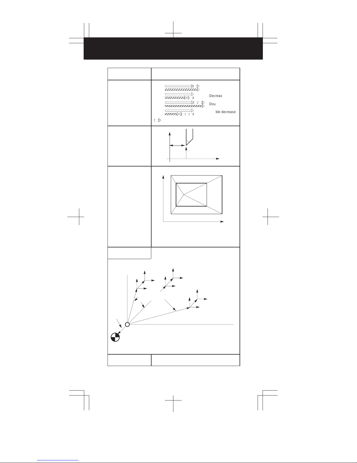
G45 Tool offset increase
G46
G47
G48 Tool offset double decrease
G49
G50
G51
G52
G53
Positioning
Linear interpolation
01
Circular interpolation/Helical interpolation CW
Advanced preview control
Exact stop
Polar coordinates command cancel
17
Polar coordinates command
XpYp plane selection Xp: X axis or its parallel axis
02 ZpXp plane selection Yp: Y axis or its parallel axis
YpZp plane selection Zp: Z axis or its parallel axis
Input in inch
Input in mm
Stored stroke check function on
04
Stored stroke check function off
Automatic tool length measurement
Corner offset circular interpolation
Cutter compensation cancel
07
Cutter compensation left
Tool length compensation + direction
Tool length compensation – direction
Tool offset decrease
Tool offset double increase
08 Tool length compensation cancel
Scaling cancel
11
Scaling
Local coordinate system setting
Machine coordinate system selection
43
Page 45

G code list (M series) (2/3)
14
15
12
16
09
01
03
05
13
10
G code Group Function
G54
G55 Workpiece coordinate system 2 selection
G56
G57
G58 Workpiece coordinate system 5 selection
G59 Workpiece coordinate system 6 selection
G60 00 Single direction positioning
G61 Exact stop mode
G62
G63
G64
G65 00 Macro call
G66
G67
G68
G69
G73
G74
G75 01 Plunge grinding cycle (0–GSC)
G76 09 Fine boring cycle
G77
G78
G79 Intermittent–feed surface grinding cycle (0–GSC)
G80
G81
G82 Drilling cycle or counter boring cycle
G83
G84 Tapping cycle
G85 Boring cycle
G86 Boring cycle
G87 Back boring cycle
G88 Boring cycle
G89 Boring cycle
G90
G91
G92 00
G94
G95
G96
G97
G98
G99
G107 00 Cylindrical interpolation
Workpiece coordinate system 1 selection
Workpiece coordinate system 3 selection
14
Workpiece coordinate system 4 selection
Automatic corner override
Tapping mode
Cutting mode
Macro modal call
Macro modal call cancel
Coordinate rotation
Coordinate rotation cancel
Peck drilling cycle
Counter tapping cycle
Direct constant–dimension plunge grinding cycle
(0–GSC)
Continuous–feed surface grinding cycle (0–GSC)
Canned cycle cancel/external operation function cancel
Drilling cycle, spot boring cycle or external operation
function
Peck drilling cycle
09
Absolute command
Increment command
Setting for work coordinate system or clamp at maxi-
mum spindle speed
Feed per minute
05
Feed per rotation
Constant surface speed control
Constant surface speed control cancel
Return to initial point in canned cycle
10
Return to R point in canned cycle
1
2
3
4
5
6
7
8
9
10
44
Page 46

4. G CODE LIST
G code list (M series) (3/3)
G code Group Function
G150
G151
G152 Normal direction control right side on
G160
G161 20 In–feed control function (0–GSC)
CAUTION
1. Multiple G codes of different groups can be specified in a single
block. When multiple G codes of one group are specified in a block,
the G code specified last is effective.
2. If any G code of group 01 is specified in a canned cycle mode, the
canned cycle is automatically cancelled and the G80 condition is
entered. However, a G code of group 01 is not af fected by any of
the canned cycle G codes.
NOTE
1. Modal G codes have the following initial conditions when the power is
turned on or the system is reset to the clear state (bit 6 of parameter No.
045).
1) Those G codes marked in Table 3 are specified automatically.
2) G20 and G21 retain their original conditions.
3) When the power is turned on, G22 is specified automatically. When
the system is reset, G22 and G23 retain their original conditions.
4) G00 or G01 is automatically selected depending on the setting of
bit 6 of parameter No. 011.
5) G90 or G91 is automatically selected depending on the setting of
bit 7 of parameter No. 030.
2. The G codes of group 00, except G10 and G11, are one–shot G codes.
3. If a G code that does not appear in the G code list is specified, or a G
code whose options are not supported is specified, alarm No. 010 is
displayed.
4. A G code is displayed from each group.
Normal direction control cancel mode
19
Normal direction control left side on
20 In–feed control function cancel (0–GSC)
45
Page 47

T series
p
06
09
08
00
01
00
00
14
12
04
G code system
(Note 7)
A B C
G00 G00
G01
G01 G01
G02 G02 G02 Circular interpolation CW
G03 G03 G03 Circular interpolation CCW
G04 G04 G04 Dwell
G10 G10 00 Data setting
G10
G11 G11 G11 Data setting mode cancel
G17 G17 G17 XpYp plane selection
G18
G18 G18
G19 G19 G19 YpZp plane selection
G20 G20 G70
G21 G21 G71
G22
G22 G22
G23 G23 G23
G25
G25 G25
G26 G26 G26
G27 G27 G27 Reference point return check
G28 G28 G28
G30 G30 G30
G31 G31 G31 Skip cutting
G32 G33 G33
G34 G34 G34
G36 G36 G36
G37 G37 G37
G40
G40 G40
G41 G41 G41
G42 G42 G42 Tool nose radius compensation right
G50 G92 G92
G52 G52 G52
G53 G53 G53 Machine coordinate system setting
G54
G54 G54
G55 G55 G55 Workpiece coordinate system 2 setting
G56 G56 G56
G57 G57 G57
G58 G58 G58 Workpiece coordinate system 5 setting
G59 G59 G59 Workpiece coordinate system 6 setting
G65 G65 G65 00 Macro calling
G66 G66 G66
G67
G67 G67
G68 G68 G68
G69 G69 G69
G code list (T series) (1/2)
Group Function
G00
Positioning (rapid traverse)
Linear interpolation (feed)
01
16 ZpXp plane selection
Inch data input
Metric data input
Stored stroke check function ON
09
Stored stroke check function OFF
Spindle speed fluctuation detect OFF
08
Spindle speed fluctuation detect ON
Return to reference point
2nd, 3rd, 4th reference point return
Thread cutting
Variable–lead thread cutting
Automatic tool compensation X
Automatic tool compensation Z
Tool nose radius compensation cancel
07
Tool nose radius compensation left
Coordinate system setting, max. spindle
speed setting
Local coordinate system setting
Workpiece coordinate system 1 setting
Workpiece coordinate system 3 setting
14
Workpiece coordinate system 4 setting
Macro modal call
Macro modal call cancel
Mirror image for double turrets ON or balance
cut mode (0–TTC)
Mirror image for double turrets OFF or bal-
ance cut mode cancel (0–TTC)
1
2
3
4
5
6
7
8
9
10
46
Page 48

4. G CODE LIST
p
01
02
05
03
11
21
G code list (T series) (2/2)
G code system
(Note 7)
A B C
G70 G70 G72
G71 G71 G73
G72 G72 G74
G73 G73 G75 00
G74 G74 G76
G75 G75 G77
G76 G76 G78
G71 G71 G72 Traverse grinding cycle (0–GCC, 00–GCC)
G72 G72 G73
G73 G73 G74
G74 G74 G75
G80
G80 G80
G83 G83 G83 Cycle for face drilling
G84 G84 G84 Cycle for face tapping
G86 G86 G86
G87 G87 G87 Cycle for side drilling
G88 G88 G88 Cycle for side tapping
G89 G89 G89 Cycle for side boring
G90 G77 G20
G92 G78 G21
G94 G79 G24 Endface turning cycle
G96 G96 G96
G97
G97 G97
G98 G94 G94
G99
G95 G95
—
G90 G90
—
G91 G91
— G98 G98
— G99 G99
G107 G107 G107
G112 G112 G112
G113
G113 G113
G250
G250
G251 G251 G251
Group Function
Finishing cycle
(other than 0–GCC or 00–GCC)
Stock removal in turning
(other than 0–GCC or 00–GCC)
Stock removal in facing
(other than 0–GCC or 00–GCC)
Pattern repeating
(other than 0–GCC or 00–GCC)
Peck drilling on Z axis
(other than 0–GCC or 00–GCC)
Grooving on X axis
(other than 0–GCC or 00–GCC)
Multiple threading cycle
(other than 0–GCC or 00–GCC)
Traverse direct constant dimension grinding
cycle (0–GCC, 00–GCC)
01
Oscillation grinding cycle
(0–GCC, 00–GCC)
Oscillation direct constant–dimension grinding cycle (0–GCC, 00–GCC)
Canned cycle for drilling cancel
10
Cycle for face boring
Outer diameter/internal diameter cutting
cycle
Thread cutting cycle
Constant surface speed control
Constant surface speed control cancel
Per minute feed
Per revolution feed
Absolute programming
03
Incremental programming
Return to initial level
Return to R point level
00 Cylindrical interpolation
Polar coordinate interpolation mode
G250
Polar coordinate interpolation cancel mode
Polygonal turning cancel
20
Polygonal turning
47
Page 49

CAUTION
1. A number of G codes can be specified in the same block. When
more than one G code of the same group is specified, the G code
specified later is effective.
2. If any G code of group 01 is specified in a canned cycle mode, the
canned cycle is automatically cancelled and the G80 condition is
entered. However a G code of group 01 is not affect4ed by any of
the canned cycle G codes.
NOTE
1. G codes marked
For G20 and G 21, the G code before turning power off remains. G00
or G01 can be selected by parameter setting.
2. G codes of group 00 are not modal. They are only effective in the block
in which they are specified.
3. If a G code not listed on the table of G codes is inputted, or optional G
code not specified in the system is commanded, an alarm (No. 010) is
displayed.
4. A G code is displayed from each group.
5. G code system B and C are options. Whether G code system B or C is
set by parameter No. 0036: GSPC.
are initial G codes when turning power on.
1
2
3
4
5
6
7
48
8
9
10
Page 50

5. PROGRAM FORMAT
Functions Explanation
Positioning (G00)
Start point
Linear interpolation
(G01)
Start point
Circular interpolation
(G02, G03)
P
P
Start point
Helical cutting
(G02, G03)
Center
(x, y)
Center
Start
point
R
J
I
G03
R
I
Z
G02
Start point
J
End point
End point
(x, y)
Tool path
YX
49
The feedrate along the circumference
of two circular interpolated axes is the
specified feedrate.
Page 51

G00P__ ;
Tape format
T
seriesMseries
f f
1
G01P__ ;
G02 R__
G17 Xp__Yp__ F__ ;
G03 I__J__
G02 R__
G18 Xp__Zp__ F__ ;
G03 I__K__
G02 R__
G19 Yp__Zp__ F__ ;
G03 I__K__
Synchronously with arc of XpYp plane
G02 I__J__
G17 Xp__Yp__ α__ F__ ;
G03 R__
Synchronously with arc of ZpYp plane
G02 I__K__
G18 Xp__Zp__ α__ F__ ;
G03 R__
Synchronously with arc of YpZp plane
G02 J__K__
G19 Yp__Zp__ α__ F__ ;
G03 R__
Any one axis where circular interpolation is
not applied.
f f
2
f f
3
4
5
6
f
7
8
9
10
50
Page 52

5. PROGRAM FORMAT
Functions Explanation
Dwell (G04) (Example)
G04 P1000; Dwell by 1 seconds
Exact stop
(G04, G09)
High-speed cycle
machining (G05)
High-speed remote
buffer A (G05)
Speed
Time
(Example)
Cycle 1: connection 2, repetition 1
Cycle 2: connection 3, repetition 3
Cycle 3: connection 0, repetition 1
G05P10001L2;
Cycle is executed as 1, 2, 2, 2, 3, 1, 2, 2, 2, 3
Specify G05 only in a block using normal NC
command format. Then specify move data in the
special format explained next page. When zero is specified as the travel distance along all axes, normal NC
command format can be used again for
subsequent command specification.
High-speed remote
buffer B (G05)
Advanced preview
control (G08)
51
High-speed remote buffer A uses binary data.
On the other hand, high-speed remote buffer B can directly use NC language coded with equipment such as
an automatic programming unit to perform
high-speed machining.
This function can minimize the delay caused by acceleration/deceleration, which increases together with the
feedrate, as well as the delay in the servo system. Tool
movement can thus faithfully follow the command values, reducing the degree of error in the machined figure.
Page 53

Tape format
X__
G04 ; Dwell by second
P__
G04 ;
G09
P
;
T
seriesMseries
f f
f
1
2
3
G05 P10 ×××L∆∆∆ ;
××× : Start program number of called programs
∆∆∆: Repetition time of machining cycle
⋅Binary input operation enabled: G05;
⋅Binary input operation disabled: The travel distance along
⋅Data format for binary input operation
Data
sequence
All data must be specified in binary.
G05P01; Start high-speed machining
X__Y__Z__;
G05P00; End high-speed machining
Byte
High byte
Low byte
High byte
Low byte
:
:
High byte
Low byte
Check byte
all axes are set to zero.
1st axis
2nd axis
Nth axis
f f
f f
4
5
6
7
8
f
9
G08 Pp;
p=1: Advanced preview control mode on
p=0: Advanced preview control mode off
f
10
52
Page 54

5. PROGRAM FORMAT
Functions Explanation
Change of offset value by
program (G10)
Change of offset value by
program (G10)
The tool compensation amount can be set or changed
with the G10 command.
When G10 is used in absolute input (G90), the
compensation amount specified in the command
becomes the new tool compensation amount.
When G10 is used in incremental input (G91), the
compensation amount specified in the command is
added to the amount currently set.
Change of parameter by
program (G10)
Polar coordinate
command mode
(G15, G16)
XpYp plane selection
(G17)
ZpXp plane selection
(G18)
YpZp plane selection
(G19)
Inch/metric conversion
(G20, G21)
Extended stored stroke
limit check on
(G22, G23)
The parameter value can be changed by the
machining program.
Y
x
y
Y
G17
(I, J, K)
X
X
G18 G19
Z
Z
(X, Y, Z)
X>I, Y>J, Z>K
X
Y
53
Page 55

Tape format
G10P__X (U)__Y (V)__Z (W)__R (C)__Q__;
For geometry offset amount
P=10000+geometry offset number
For offset amount
P= wear offset number
R : Tool nose radius offset value
Q : Imaginary tool nose number
T
seriesMseries
f
1
2
G10L__PpRr;
p : Offset No.
r : T ool compensation amount
Format
(1) For tool compensation memory A
G10 L11 P__R__;
(2) For tool compensation memory B
Setting/changing the geometric compensation amount
G10 L10 P__R__;
Setting/changing the wear compensation amount
G10 L11 P__R__;
G10 L50 ;
N__P__ ;
G11
N : Parameter number
P : Parameter value
G16 ; Polar coordinate command
Xx
Yy ;
x: radius, y: angle (*)
G15 ; Polar coordinate command cancel
G17 ;
G18 ;
G19 ;
G20 ; Inch input
G21 ; Metric input
G22X__Y__Z__I__J__K__ ; on
G23 ; off
(X, Z, I and K only for T series)
f f
f f
f f
f f
f
3
4
5
f
6
7
8
9
10
54
Page 56

5. PROGRAM FORMAT
Functions Explanation
Spindle speed
fluctuation detection
on (G26)
Spindle speed
fluctuation detection
off (G25)
(Example)
(1) When an alarm is raised after a specified spindle speed is reached
Spindle speed
Reference for spindle speed at which
check is started
Specified
r
speed
Fluctuation at which
alarm is raised (r)
Check
Specification of
another speed
(2) When an alarm is raised before a specified spindle speed is
reached
Spindle speed
Specification of
another speed
Reference position
return check (G27)
Spindle speed specified by q
q
Check
No check
Alarm
Start of check
Spindle speed specified by r
P
No check
Start of check
Start point
CheckCheck
Alarm
Actual speed
(detected by position
coder)
Time
r
Actual
speed
Time
Reference position
Specified
speed
P
55
Page 57

Tape format
G26PpQqRr ; spindle fluctuation detection on
p: Time (in ms) from the issue of a new spindle rotation
command (S command) to the start of checking whether
the actual spindle speed is so fast that an overheat can
occur. (When a specified speed is reached within the time
period of P, a check is started at that time.)
q: Tolerance (%) of a specified spindle speed (If a specified
spindle speed lies within this range, it is regarded as
having reached the specified value. Then, the checking
of an actual spindle speed is started.)
q = (1 – actual spindle speed/specified spindle speed)
× 100
r: Spindle speed fluctuation (%) at which the actual spindle
speed is so fast that an overheat can occur
r = (1 – speed that can cause overheat/specified spindle
speed) × 100
G26 enables the spindle speed fluctuation detection
function, and G25 disables the spindle speed fluctuation
detection.
G25 ; Spindle fluctuation detection off
T
seriesMseries
f
1
2
3
4
5
6
G27P__ ;
7
8
9
10
f f
56
Page 58

5. PROGRAM FORMAT
F: Lead
Functions Explanation
Reference position
return (G28)
2nd, 3rd, 4th reference
position return (G30)
Reference poisition
Intermediate point
P
Start point
Return to reference
position return start
position (G29)
Skip function (G31)
Multi-step skip function
(G31)
Equal lead thred cutting
(G32)
Thread cutting (G33)
Variable lead thread
cutting
Automatic tool compensation (G36, G37)
Reference position
Start point
Starting point
Specified position
(Xa or Za)
Intermediate position
Skip signal
Measured position
reach signal
Offset value set
by this command
P
P
Measured
position
57
Page 59

G28P__ ;
P2
G30 P3
P4
G29P__ ;
Tape format
P2: 2nd reference position return
P
__ ;
P3: 3rd reference position return
P4: 4th reference position return
T
seriesMseries
f f
f
1
2
3
G31P__F__ ;
Move command
G31
P
__F__P__;
F__: Feedrate
P__: P1-P4
Dwell
G04X (U, P)__(Q__);
X(U, P)__: Dwell time
Q__: Q1-Q4
G32P__F__ ;
G33P__F__ ;
G34P__FfKf ;
f: Longer axis lead at the start position
k: increase/decrease value per spindle revolution
G36X xa ;
G37Z za
;
X xa, Z za: Specified position
f f
GCC
f
f
f
4
5
f
6
7
8
9
10
58
Page 60

5. PROGRAM FORMAT
ÇÇ
ÇÇ
Functions Explanation
Automatic tool length
measurement (G37)
Tool nose radius
compensation
(G40, G41, G42)
Cutter compensation B
(G39 to G42)
Cutter compensation
(G40 to G42)
Tool length
compensation A, B, C
(G43, G44, G49)
Z
Rapid
traverse
Measurement
feedrate
0
Compensation value = (Current compensation value)
+ [(Coordinates of the point at which the tool is
stopped) – (Coordinates of the programmed
measurement position)]
G40
G40 : Programmed path
G41 : Left of programmed path
G42 : Right of programmed path
G40
G40 : Programmed path
G41 : Left of programmed path
G42 : Right of programmed path
A (Start position)
Measurement position is
commanded with G37
B (Deceleration position)
C (Measurement position)
The tool stops when the
approach end signal
goes on.
X
G41
G42
G41
G42
59
G43: + offset
G44: – offset
Offset
Z
Page 61

Tape format
G92P__;Sets the workpiece coordinate system. (It can be
set with G54 to G59.)
Hff; Specifies an offset number for tool length offset.
G90 G37P__; Absolute command
⋅G37 is valid only in the block in which it is
specified.
P__ indicates the X-, Y-, Z-, or fourth axis.
T
seriesMseries
f
1
2
3
G40
G41
P
G42
G39X(I)__Y(J)__ ;
Corner offset circular interpolation
(Cutter compensation B only)
G17 G40
G18 G41 D(H)__ ;
G19 G42
D(H): Tool offset number
G43
G44
G17 X__
G18 Y__ H__ ;
G19 Z__
G43 α__H__ ; Tool length compensation C
G44
H: Offset number
α: Arbitrary one axis
G49 ; T ool length compensation cancel
__ ;
(Z__)H__ ; T ool length compensation A
G43
G44
Tool length compensation B
f
4
5
f
6
7
f
8
9
10
60
Page 62
5. PROGRAM FORMAT
Functions Explanation
Tool offset
(G45 – G48)
Coordinate system
setting
Spindle speed setting
(G50)
G45
G46
G47
G48
: offset value
X
Increases
Decrease
Double increase
Double decrease
P
Z
Scaling (G50, G51)
Local coordinate
system setting (G52)
(Parameter
value)
(Origin of the machine coordinate system)
(Reference position)
P
P
to P4: Programmed shape
1
P
’ to P4’: Scaled shape
1
P0: Scaling center
(Local coor-
dinate system)
(Workpiece
coordinate
system 1:
G54)
(Workpiece reference
position offset)
P
(Machine coordinate system)
P3’
P
3
4
P4’
P
0
P2’
P1’
P
1
(Local coordinate
system)
P
2
(Workpiece coordinate system 2:G55)
(Workpiece
coordinate system)
P
(Workpiece coordinate
system 6:G59)
Machine coordinate
system selection (G53)
61
Page 63

Tape format
G45 (increase)
G46 (decrease)
G47 (double increase)
G48 (double decrease)
X__
Y__ Dxx ;
Z__
T
seriesMseries
f
1
2
G50X__Z__ ; Coordinate system setting
G50S__ ; Spindle speed setting
G51X__Y__Z__P__(or I__J__K__) ;
G50 ; Cancel
X, Y, Z: Scaling center
P: Magnification
(I, J, and K are the scaling magnifications for the X-, Y-, and
Z-axes respectively.)
G52P__ ; Local coordinate system setting
G52
P
0 ; Local coordinate system cancel
f
3
4
f
5
6
7
f f
8
9
G53P__ ;
10
f f
62
Page 64

5. PROGRAM FORMAT
Functions Explanation
Work coordinate
system 1 – 6
selection
(G54 – G59)
Workpiece
coordinate
system 1
ZOFS1: Reference position offset for workpiece coordinate system 1
ZOFS2: Reference position offset for workpiece coordinate system 2
ZOFS3: Reference position offset for workpiece coordinate system 3
ZOFS4: Reference position offset for workpiece coordinate system 4
ZOFS5: Reference position offset for workpiece coordinate system 5
ZOFS6: Reference position offset for workpiece coordinate system 6
Additioonal work
coordinate system
selection (G54P)
Spindle direction
positioning (G60)
Exact stop mode (G61)
Workpiece
coordinate
system 2
ZOFS2 ZOFS3 ZOFS4
ZOFS1
Machine reference
position
(Example)
G54P12 ;
Selecting additional work coordinate system 12
Start point
End point
End point
Speed
Workpiece
coordinate
system 3
ZOFS5
ZOFS6
Overrun
Workpiece
coordinate
system 4
Workpiece
coordinate
system 5
Workpiece
coordinate
system 6
Start point
Temporary stop
Automatic corner override (G62)
63
a
Le
Override is applied from a to b
Time
Programmed path
Ls
a
Page 65

Tape format
G54P__ ; Work coordinate system 1 selection
G55
P
__ ; Work coordinate system 2 selection
G56
P
__ ; Work coordinate system 3 selection
G57
P
__ ; Work coordinate system 4 selection
G58
P
__ ; Work coordinate system 5 selection
G59
P
__ ; Work coordinate system 6 selection
T
seriesMseries
f f
1
2
3
4
G54Pn ; (n=1 – 64)
G60P__ ;
G61 ;
G62 ;
f
f
5
6
7
f
8
f
9
10
64
Page 66

5. PROGRAM FORMAT
Functions Explanation
Tapping mode (G63)
Cutting mode (G64)
Macro call (G65)
Speed
Speed
Feed hold is ineffective
Main program Macro program
O__:
G66P0001L__:
M02;
Feedrate override
is ineffective
O0001;
M99
Time
Time
Macro model call
(G66, G67)
Mirror image for double
turrets (G68, G69)
Coordinate rotation
(G68, G69)
Main program Macro program
O__:
G66P0001L__;
X__
Y__
G67;
Y’
Y
O0001;
M99
X’
R
X
65
Page 67

G63 ;
Tape format
T
seriesMseries
f
1
2
G64 ;
G65 P__L__ ;
P: Program number
L: Repetition count (1 to 9999)
G66 P__L__ ;
G67 ; Cancel
P: Program number
L: Repetition count (1 to 9999)
G68 ;
Mirror image for double turrets
G69 ;
Mirror image cancel
G17
G18 G68 α__β__R__ ;
G19
G69 ;
α, β: 3 axes corresponding to G17, G18, G19
R: Routation angle
f f
f
TT
f
3
4
5
f
6
7
8
f
9
10
66
Page 68

5. PROGRAM FORMAT
Functions Explanation
Canned cycle for
lathes
(G70 to G76)
(G90, G92, G94)
Zero point
Canned cycle
G90: Outer diameter/internal diameter cutting cycle
G92: Thread cutting cycle
G94: End face turning cycle
Multiple repetitive cycle
G70: Finishing
G71: Stock removal in turning
G72: Stock removal in facing
G73: Pattern repeating
G74: End face peck drilling cycle
G75: Outer diameter/internal diameter drilling cycle
G76: Multiple thread cutting cycle
(Example) G92
X axis
Z W
4(R)
3(R)
Approx.
45°
r
Detailed chamfered thread
1(R)
3(R)
U/2
X/2
Z axis
R Rapid .
F Specified.
L
(The chamfered angle in
the left figure is 45 degrees
or less because of the
delay in the servo system.)
traverse
by F code
67
Page 69

Tape format
G70 P__Q__ ;
G71 U__R__ ;
G71 P__Q__U__W__F__S__T__ ;
G72 W__R__ ;
G72 P__Q__U__W__F__S__T__ ;
G73 W__R__ ;
G73 P__Q__U__W__F__S__T__ ;
G74 R__ ;
G74 X(u)__Z(w)__P__Q__R__F__ ;
G75 R__ ;
G75 X(u)__Z(w)__P__Q__R__F__ ;
G76 R__ ;
G76 X(u)__Z(w)__P__Q__R__F__ ;
T
seriesMseries
f
1
2
3
G90
G92 X__Z__I__F__ ;
G94 X__Z__I__F__ ;
4
5
6
7
8
9
10
68
Page 70

5. PROGRAM FORMAT
Functions Explanation
Canned cycle for
grinding (G71 – G74)
G71: Traverse grinding cycle
G72: Traverse direct fixed-dimension grinding cycle
G73: Oscillation grinding cycle
G74: Oscillation direct fixed-dimention grinding cycle
(Example) G71
G71 A__B__W__U__I__K__H__ ;
X
A
B
A: First depth of cut
B: Second depth of cut
W: Grinding range
U: Dwell time Maximum specification
I: Feedrate of A and B
K: Feedrate of W
H: Number of repetitions
1(1)
2
U
time: 99999.999 seconds
Setting value: 1 to 9999
W
3(K)
6(K)
4(1)
5
Z
Canned cycle (G73, G74,
G80 – G89)
(Example)
G73 (G98)
R point
q
q
q
69
G73: High-speed peck drilling cycle
G74: Left-hand tapping cycle
G76: Fine boring cycle
G80: Cancel
G81: Drilling cycle, spot drilling cycle
G82: Drilling cycle, counter boring cycle
G83: Peck drilling cycle
G84: Tapping cycle
G85: Boring cycle
G86: Boring cycle
G87: Boring cycle/Back boring cycle
G88: Boring cycle
G89: Boring cycle
Initial level
d
d
Z point
G73 (G99)
q
q
q
R point
d
d
Z point
Page 71

Tape format
G71 A__B__W__U__I__K__H__ ;
G72 P__A__B__W__U__I__K__H__ ;
G73 A__(B__)W__U__I__K__H__ ;
G74 P__A__(B__)W__U__I__K__H__ ;
G73 X__Y__Z__P__Q__R__F__K__ ;
G74 X__Y__Z__P__Q__R__F__K__ ;
G76 X__Y__Z__P__Q__R__F__K__ ;
G81 X__Y__Z__P__Q__R__F__K__ ;
G82 X__Y__Z__P__Q__R__F__K__ ;
G83 X__Y__Z__P__Q__R__F__K__ ;
G84 X__Y__Z__P__Q__R__F__K__ ;
G85 X__Y__Z__P__Q__R__F__K__ ;
G86 X__Y__Z__P__Q__R__F__K__ ;
G87 X__Y__Z__P__Q__R__F__K__ ;
G88 X__Y__Z__P__Q__R__F__K__ ;
G89 X__Y__Z__P__Q__R__F__K__ ;
G80 ; Cancel
Gj j X__Y__Z__R__Q__P__F__K__ ;
T
seriesMseries
GCC
f
1
2
3
4
5
6
Hole position data
Drilling mode
Drilling mode Gj j
Hole position data X,Y
Drilling data
Number of repeats K
Drilling data
Item Address
Z
R
Q
P
F
Number of repeat
G73, G74, G76, G80 – G89
Specifies the hole position by an
incremental or absolute value.
Specifies the distance from point R to the
bottom of the hole.
Specifies the distance from the initial
level to point R.
Specifies each cut-in value with G73 and
G83 or the shift value with G76 and G87.
(Always specified with an incremental
value.)
Specifies the dwell time at the bottom of
the hole.
Specifies the feed rate.
Specifies the number of repeats for a
series of operation 1 to 6.
Explanation
7
8
9
10
70
Page 72

5. PROGRAM FORMAT
Functions Explanation
Canned grinding cycle
(G75, G77, G78, G79)
(Example)
X
I
J
G75 I__J__K__X (Z)__R__F__P__L__ ;
I: Depth-of-cut 1 (A sign in the command specifies the direction of cutting.)
J: Depth-of-cut 2 ( A sign in the command specifies the direction of cutting.)
K: Total depth of cut
X (Z): Range of grinding (A sign in the command specifies the direction of
grinding.)
R: Feedrate for I and J
F: Feedrate for X (Z)
P: Dwell time
L: Grinding-wheel wear compensation (Note 1)
Canned cycle for
drilling (G80 to G89)
(Example)
G83 (G87) (G99 mode)
(Ma)
G75: Plunge grinding cycle
G77: Direct constant-dimension plunge
grinding cycle
G78: Continuous-feed surface grinding cycle
G79: Intermittent-feed surface grinding cycle
X(Z)
(1) (R)
(2) P
(3) (F)
(6) (F)
G83: Front drilling cycle
G84: Front tapping cycle
G85: Front boring cycle
G87: Side drilling cycle
G88: Side tapping cycle
G89: Side boring cycle
G80: Drilling cycle cancel
G83 (G87) (G98 mode)
(Ma)
(4) (R)
(5) P
X(Z)
Initial level
71
R point level
P
(Mβ), ’
q
q
q
d
dwell
Z point
dwell
P
q
q
q
R point level
d
P
dwell
(Mβ), ’
dwell
Z point
P
Page 73

Tape format
G75 I__J__K__X (Z)__R__F__P__L__ ;
G77 I__J__K__X (Z)__R__F__P__L__ ;
G78 I__J__K__X (Z)__R__F__P__L__ ;
G79 I__J__K__X (Z)__R__F__P__L__ ;
T
seriesMseries
GSC
1
2
3
4
G83 X(Z)__C__Z(X)__R__Q__P__F__K__(M_) ;
G84 X(Z)__C__Z(X)__R__Q__P__F__K__(M_) ;
G86 X(Z)__C__Z(X)__R__Q__P__F__K__(M_) ;
G87 X(Z)__C__Z(X)__R__Q__P__F__K__(M_) ;
G88 X(Z)__C__Z(X)__R__Q__P__F__K__(M_) ;
G89 X(Z)__C__Z(X)__R__Q__P__F__K__(M_) ;
G80 ; Cancel
GVV X(Z)__C__Z(X)__R__Q__P__F__K__(MVV) ;
Hole position data
Drilling mode
Designation Address
Drilling mode GVV
Hole position X/U
Drilling data
Number of repeats K
M code of C-axis clamp
Drilling data
(Z/W)C/H
Z(X)
MVV
R
Q
P
F
Number of
repeat
G80, G83, G84, G86 to G89
Specifies the hole position by an
incremental or absolute value.
Specifies the distance from point R to the
bottom of the hole.
Specifies the distance from the initial
level to point R level.
Specifies each cut-in value with G83
(G87). This value is always specified
with an incremental value to specify
radius.
Specifies the dwell time at the bottom of
the hole.
Specifies the feedrate.
Specifies the number of repeats for a
series of operations.
M-code (specified by a parameter) of C-
axis clamp.
Description
f
5
6
7
8
9
10
72
Page 74

5. PROGRAM FORMAT
Functions Explanation
Absolute/Incremental
command (G90/G91)
Change of workpiece
coordinate system (G92)
Feed/minute,
Feed/revolution
(G94, G95)
Constant suface speed
control (G96, G97)
(Example)
Absoulute command G90X100Y60 ;
Incremental command G91X50Y30 ;
Feed/minute (G94) Feed/revolution (G95)
F
60
30
Y
Move
distance
per minute
50
P
X
F
Surface speed
100
Move
distance
per revolution
Constant surface speed
control (G96, G97)
Initial point return/R
point return (G98, G99)
Cylindrical interpolation
(G107)
73
X
Z(X=0)
G98
Initial point
G99
C
Z
R point
Z point
R
Page 75

Tape format
G90__ ; Absolute command
G91__ ; Incremental command
G90__G91__ ; Change of workpiece coordinate system
G92P__ ; f
T
seriesMseries
f
(G code
system
B, C)
f
1
2
3
G94 F__ ;. . . . . .
G95 F__ ;. . . . . .
(T series
<G code system B, C>
M series)
G96 Ss ;
G97 ; Cancel
s: Surface speed (m/min or feet/min)
G96 Ss Pα ;
G97; Cancel
α: 1 – 3
(X axis, Y axis, Z axis)
s: Surface speed (m/min or feet/min)
G98__ ;
G99__ ;
G107 Cr;
Cylindrical interpolation mode
C: Rotary axis name
r: Radius of cylinder
G107 CO;
Cylindrical interpolation mode cancel
or
G98 F__ ;. . . . . .
G99 F__ ;. . . . . .
(T series
<G code system A>
f f
f
f
(G
coed
system
B, C)
f f
4
5
6
f
7
8
f
9
10
74
Page 76

5. PROGRAM FORMAT
Functions Explanation
Polar coordinate
interpolation mode
(G112, G113)
C
C axis
X axis
Normal direction control
(G140, G141, G142)
Infeed control (G160,
G161)
Polygon turning
(G250, G251)
Tool
(Example)
Y
C axis
Normal direction
(proceeding direction)
rrr r
Start point
Z
Workpiece
C axis
Tool
Workpiece
Programmed
path
End point
Tool
75
Page 77

Tape format
G112 ;
Polar coordinate interpolation mode
G113 ;
Polar coordinate interpolation mode cancel
T
seriesMseries
f f
1
2
G140 ; Normal direction control cancel
G141 ; Normal direction control left
G142 ; Normal direction control right
G160 ; Cancel
G161 Rr
;
r: Cut in depth
G250 ;
Polygon turning cancel
G251P__Q__ ;
Polygon turning
P, Q: Potation ratio of spindle and workpiece
f
3
4
0–GSC
5
6
f
7
8
9
10
76
Page 78

5. PROGRAM FORMAT
FS0–TC/FS15–T A format comparison table
Function comparison
A : Both models have the same functions and formats.
B : Both models have the same functions, but different formats.
C : Both models have the same formats, but different functions.
D : The models have different functions and formats.
Item
1 Positioning G00X––Z––;
2 Linear interpolation G01X––Z––F––;
3 Circular interpolation G02/03X––Z––R––(I––K––)F––;
4 Dwell G98G04P––/X––/U––;
5 Cylindrical interpolation G07.1
6 Data setting G10L11P––X––Z––Y––R––Q––;
7 Polar coordinate interpolation
8 Polar coordinate interpolation
9 Plane selection G17/G18/G19
10 Inch input G20
11 Metric input G21
12 Stored stroke check ON G22X––Z––I––K––;
13 Stored stroke check OFF G23;
14 Spindle speed fluctuation
15 Spindle speed fluctuation
16 Reference position return
17 1st reference position return
18 nth reference position return
19 Skip cutting G31X–Z––;
20 Thread cutting G32X––Z––F––Q––;
Function FS15–TA
G99G04P––/X––/U––;
Rotation axis name and cylinder diameter
G10L10P––X––Z––Y––R––Q––;
mode
cancel mode
detection OFF
detection ON
check
check
check
G12.1
G13.1
G25;
G26P––Q––R––D––;
G27X––Z––;
G28X––Z––;
G30P2/3/4X––Z––;
G32X––Z––E––Q––;
(in time units)
(in rotation units)
L11 Wear compensation
L10 Geometric compensation
P : Check start timer
Q : Check start tolerance ratio
R : Minimum variation ratio de-
tected as an alarm
D : Minimum variation width de-
tected as an alarm
Q : Threading start shift angle
E : Number of screw threads per
inch
77
Page 79

1
FS0–TC
G00X––Z––; C
G01X––Z––F––; A
G02/03X––Z––R––(I––K––)F––; C
G04P––/X––/U––; (in time units) C
G107
Rotation axis name and cylinder diameter
G10P––X––Z––Y––R––Q––;
For wear compensation,
P : Wear compensation num-
ber
For geometric compensation,
P : 10000 + geometric com-
pensation number
G112 B
G113 B
G17/G18/G19 A
G20 C
G21 C
G22X––Z––I––K––; A
G23; A
G25; A
G26P––Q––R––;
P : Check start timer
Q : Check start tolerance ratio
R : Minimum variation ratio de-
tected as an alarm
FS0–TC tape
format conversion
Function
comparison
2
3
B
B
4
5
6
7
8
C
9
G27X––Z––; A
G28X––Z––; A
G30P2/3/4X––Z––; A
G31X––Z––; A
G32X––Z––F––; G32X––Z––E––
E : Lead along the ma-
jor axis.
It is impossible to specify
the number of screw
threads per inch and the
threading start shift angle.
10
D
78
Page 80

5. PROGRAM FORMAT
Item
21 Variable lead thread cutting G34X––Z––F––K––;
22 Automatic tool offset G37.*X/Z––;
23 Tool nose radius compensation
24 Tool nose radius compensation
25 Tool nose radius compensation
26 Coordinate system setting G50X––Z––;
27 Polygon turning cancel G50.2
28 Polygon turning G51.2P––Q––;
29 Local coordinate system set-
30 Machine coordinate system se-
31 Workpiece coordinate system
32 Macro calling G65P––L––Argument;
33 Macro modal calling G66P––L––Argument;
34 Macro modal calling cancel G67;
35 Mirror image ON for double tur-
36 Mirror image OFF for double
37 Finishing cycle G70P––Q––;
38 Outer surface rough cutting
Function FS15–TA
cancel
(Left)
(Right)
ting
lect
select
ret
turret
canned cycle
G40
G41
G42
G52X––Z––;
G53X––Z––;
G54 to G59
G68;
G69;
G71P––Q––U––W––I––K––D––F––
S––T––;
39 End face rough cutting canned
cycle
40 Closed–loop turning canned
cycle
41 End face cutting–off canned
cycle
42 Outer surface/inner surface
cutting–off canned cycle
79
G72P––Q––U––W––I––K––D––F––
S––T––;
G73P––Q––U––W––I––K––D––F––
S––T––;
G74X––Z––I––K––F––D––;
G75X––Z––I––K––F––D––;
Page 81

FS0–TC
G34X––Z––F––K––; A
G36X––; X axis
G37X––; Z axis
G40 A
G41 A
G42 A
FS0–TC tape
format conversion
Function
comparison
1
D
2
G50X––Z––; A
G250 B
G251P––Q––; B
G52X––Z––; A
G53X––Z––; A
G54 to G59 C
G65P––L––Argument; A
G66P––L––Argument; C
G67; A
G68; A
G69; A
G70P––Q––; A
G71U––R––;
G71P––Q––U––W––D––F––
S––T––;
G72U––R––;
G72P––Q––U––W––F––S––T––;
G73U––R––;
G73P––Q––U––W––F––S––T––;
G74R––;
G74X––Z––P––Q––R––F––;
G75R––;
G75X––Z––P––Q––R––F––;
G71P––Q––U––W––F––
S––T––;
It is impossible to specify a
cutting allowance for
roughing. (I,K)
An attempt to specify it is
ignored.
G72P––Q––U––W––D––
F––S––T––;
It is impossible to specify a
cutting allowance for
roughing. (I,K)
An attempt to specify it is
ignored.
G73P––Q––U––W––I––
K––D––F––S––T––;
G74X––Z––I––K––
F––D––;
G75X––Z––I––K––
F––D––;
D (C)
D (C)
B (A)
B (A)
B (A)
3
4
5
6
7
8
9
10
80
Page 82

5. PROGRAM FORMAT
Item
43 Multiple repetitive canned
44 Canned cycles for drilling G8*X––Y––Z––R––Q––P––F––L––;
45 Outer surface/inner surface
46 Threading canned cycle G92X––Z––I––F––Q––;
47 End face turning canned cycle G94X––Z––K––F––;
48 Constant surface speed control G96S––;
49 Constant surface speed control
50 Feed per minute G98
51 Feed pre revolution G99
52 Sub program calling M98P––L––;
Function FS15–TA
cycle for threading
turning canned cycle
cancel
G76X––Z––I––K––D––F––A––
G90X––Z––I––F––;
G97S––;
P––Q––;
L : Number of repeat
81
Page 83

FS0–TC
G76P––Q––R––;
G76X––Z––R––P––Q––F––;
G8*X (Z)––C––Z (X)––R––Q––
P––F––K––;
K : Number repeat
G90X––Z––R––F––; G90X––Z––I––F––; B (A)
G92X––Z––R––F––; G92X––Z––I––F––Q––; D (C)
G94X––Z––R––F––; G94X––Z––K––F––; B (A)
G96S––; C
G97S––; A
G98 A
G99 A
M98P––; M98P––L––;
FS0–TC tape
format conversion
G76X––Z––I––K––D––F––
A––P––Q––;
A threading method (P)
can be selected only from
P1 (single–edge cutting
with constant cutting
amount) and P2 (jigzag
cutting with constant cutting amount). It is impossible to specify an arbitrary
angle for the tool tip (A). If
an angle other than those
that can be specified in
Series 0 (0, 29, 30, 55, 60,
or 80 degrees) is specified,
alarm P/S 062 is generated.
G8*X (Z)––C––Z (X)––R––
Q––P––F––L––;
L : Repetition count
It is impossible to select
an arbitrary drill axis.
If a number with more than
three digits is specified in
calling a subprogram, the
lower three digits are regarded as a subprogram
number (address P). If the
number of repetitive calls
is not specified, it is assumed to be 1.
Function
comparison
D (C)
D (C)
B (A)
1
2
3
4
5
6
7
8
9
10
82
Page 84

5. PROGRAM FORMAT
FS0–MC/FS15–MA format comparison table
Function comparison
A : Both models have the same functions and formats.
B : Both models have the same functions, but different formats.
C : Both models have the same formats, but different functions.
D : The models have different functions and formats.
Item
1 Positioning G00P––;
2 Linear interpolation G01P––F––;
3 Circular interpolation G17G02/G03X––Y––R––(I––J––)F––;
4 Dwell G98G04P––/X––/U––;
5 Exact stop G09
6 Data setting G10L––P––R––;
7 Polar coordinate command
8 Polar coordinate command G16
9 Plane selection G17/G18/G19
10 Inch input G20
11 Metric input G21
12 Stored stroke check ON G22X––Y––Z––I––J––K––;
13 Stored stroke check OFF G23;
14 Reference position return
15 1st reference position return G28P––;
16 Return form reference position G29P––;
17 nth reference position return G30P2/3/4P––;
18 Skip cutting G31P––;
19 Thread cutting G33P––F––Q––;
20 Automatic tool offset G37––;
21 Corner arc G39I/K/J––J/I/K––;
22 Cutter compensation cancel G40
23 Cutter compensation (Left) G41
24 Cutter compensation (Right) G42
25 Tool length compensation (+) G43
26 Tool length compensation (–) G44
27 Tool offset increase G45
28 Tool offset decrease G46
29 Tool offset double increase G47
30 Tool offset double decrease G48
Function FS15–MA
G18G02/G03Z––X––R––(K––I––)F––;
G19G02/G03Y––
(in time units)
G99G04P––/X––/U––;
(in rotation units)
cancel
check
G15
G27P––;
G33X––Z––E––Q––;
Z––R––(J––K––)F––;
Q : Threading start shift angle
E : Number of screw threads per
inch
83
Page 85

FS0–MC
G00P––; C
G01P––F––; A
G17G02/G03X––
Y––R––(I––J––)F––;
G18G02/G03Z––
X––R––(k––I––)F––;
G19G02/G03Y––
Z––R––(J––K––)F––;
G04P––/X––/U––; (in time units) C
FS0–MC tape
format conversion
Function
comparison
1
2
3
C
4
G09 A
G10L––P––R––; A
G15 A
G16 A
G17/G18/G19 A
G20 C
G21 C
G22X––Y––Z––I––J––K––; A
G23; A
G27P––; A
G28P––; A
G29P––; A
G30P2/3/4––; A
G31P––; C
G33P––F––; D
G37––; A
G39X/Z/Y(I/K/J)––Y/X/Z(J/I/K)––; B
G40 A
G41 A
G42 A
G43 A
G44 A
G45 A
G46 A
G47 A
G48 A
5
6
7
8
9
10
84
Page 86

5. PROGRAM FORMAT
Item
31 Tool length compensation can-
32 Scaling cancel G50
33 Scaling G51X––Y––Z––P––;
34 Local coordinate system set-
35 Machine coordinate system se-
36 Workpiece coordinate system
37 Single direction positioning G60P––;
38 Exact stop mode G61
39 Automatic corner override G62
40 Tapping mode G63
41 Cutting mode G64
42 Macro calling G65P––L––Argument;
43 Macro modal calling G66P––L––Argument;
44 Macro modal calling cancel G67;
45 Coordinate rotation (G17/G18/G19) G68a––b––R––;
46 Coordinate rotation cancel G69;
47 Canned cycles for drilling G**X––Y––Z––R––Q––P––F––L––;
48 Rigid tapping M**S––;
49 Absolute command G90
50 Increment command G91
51 Coordinate system setting (G90) G92P––;
52 Feed per minute G94
53 Feed per revolution G95
54 Constant surface speed control G96S––;
55 Constant surface speed control
56 Sub program calling M98P––L––;
Function FS15–MA
cel
ting
lect
select
cancel
G49
G52P––;
(G90) G53P––;
G54 to G59
G84.2/.3X––Y––Z––R––Q––P––
G97S––;
L : Number of repeat
F––L––;
L : Number of repeat
85
Page 87

FS0–MC
G49 A
G50 A
G51X––Y––Z––P––; A
G52P––; A
(G90) G53P––; A
G54 to G59 C
G60P––; C
G61 A
G62 A
G63 A
G64 A
G65P––L––Argument; A
G66P––L––Argument; C
G67; A
(G17/G18/G19) G68a––b––R––; A
G69; A
G**X––Y––Z––R––Q––P––
F––K––;
K : Number of repeat
M**S––;
G84X––Y––Z––R––Q––P––
F––K––;
K : Number of repeat
G90 A
G91 A
(G90) G92P––; A
G94 A
G95 A
G96S––; A
G97S––; A
FS0–MC tape
format conversion
G**X––Y––Z––R––Q––
P––F––L––;
L : Number of repeat
M**S––;
G84X––Y––Z––R––Q––
P––F––L––;
L : Number of repeat
Function
comparison
D (C)
B (A)
1
2
3
4
5
6
7
8
M98P––; M98P––L––;
If a number with more than
three digits is specified in
calling a subprogram, the
lower three digits are regarded as a subprogram
number (address P). If the
number of repetitive calls
is not specified, it is assumed to be 1.
B (A)
9
10
86
Page 88

6. CUSTOM MACRO
6.1 Custom Macro A
6.1.1 Types of variables
Type of variable Variable number
Common variable #100 – #149
System variable #1 – #99
6.1.2 System variable
Variable number Contents Purpose Series
#1000 – #1015 Corresponds to UI000 to
#1032 Unified input of UI000 to
#1100 – #1115 Corresponds to UO000
#1132 Unified output of UO000
#1133 Unified output of UO100
#2001 – #2032 Wear offset value
#2701 – #2732 Geometry offset value
#2101 – #2132 Wear offset value
#2801 – #2832 Geometry offset value
#2201 – #2232 Wear offset value
#2901 – #2932 Geometry offset value
#2301 – #2332 Wear offset value
#2301 – #2332 Geometry offset value
#2401 – #2432 Wear offset value
#2451 – #2432 Geometry offset value
#2001 – #2200
(#1 – #99)
#3011 Year, month, day
#3012 Hour, minute, second
#3901 No. of parts machined
#3902 No. of parts machined
UI015
UI015
to UO015
to UO015
to UO131
(Offset No. 1 – 32)
(Offset No. 1 – 32)
(Offset No. 1 – 32)
(Offset No. 1 – 32)
(Offset No. 1 – 32)
(Offset No. 1 – 32)
(Offset No. 1 – 32)
(Offset No. 1 – 32)
(Offset No. 1 – 32)
(Offset No. 1 – 32)
Tool compensation
(Offset No. 1 – 99)
#500 – #531
#1000 – #5084
Interface input signal
Interface output
signal
X axis offset T
Z axis offset T
Tool nose radius
compensation
Imaginary tool tip
position
Y axis offset T
Tool compensation
(Offset memory A)
Clock T/M
No. of parts T/M
T/M
T/M
T
T
M
87
Page 89

Variable number SeriesPurposeContents
#4001 – #4022 G code (group 01 – 22)
#4102 B code
#4109 F code
#4111 H code
#4113 M code
#4114 Sequence number
#4115 Program number
#4119 S code
#4120 T code
#5001 – #5004 1st axis block end posi-
#5021 – #5024 1st axis current position
#5041 – #5044 1st axis current position
#5061 – #5064 1st axis skip signal posi-
#5081 – #5084 1st axis tool offset value
tion
:
4th axis block end position
:
4th axis current position
:
4th axis current position
tion
:
4th axis skip signal position
:
4th axis tool offset value
Modal information T/M
Block end position
(Workpiece coordinate)
Machine coordinate
Workpiece coordinate
Skip signal position
(Workpiece coordinate)
Tool offset value T/M
6.1.3 Argument specification (M series)
Correspondence between addresses and variable numbers
Variable number
(value)
#8004 #8104 I
#8005 #8105 J
#8006 #8106 K
#8009 #8109 F
#8010 #8110 G
#8011 #811 1 H
#8013 #8113 M
#8014 #8114 N
#8016 #8116 P
#8017 #8117 Q
#8018 #8118 R
#8019 #8119 S
#8020 #8120 T
#8024 #8124 X
#8025 #8125 Y
#8026 #8126 Z
Variable number
(flag)
Address
T/M
T/M
T/M
T/M
1
2
3
4
5
6
7
8
9
10
88
Page 90

6. CUSTOM MACRO
Correspondence between G codes of the argument
specification and variable numbers
Variable
number
(value)
#8030 #8130 00 One shot and others
#8031 #8131 01 G00, G01, G02, G03
#8032 #8132 02 G17, G18, G19
#8033 #8133 03 G90, G91
#8035 #8135 05 G94
#8036 #8136 06 G20, G21
#8037 #8137 07 G40, G41, G42
#8038 #8138 08 G43, G44, G49
#8039 #8139 09 G73, G74, G76, G80 to G89
#8040 #8140 10 G98, G99
#8041 #8141 11 G50, G51
#8042 #8142 12 G66, G67
#8045 #8145 15 G61, G62, G63, G64
#8046 #8146 16 G68, G69
Variable
number
(flag)
G code
group
number
G codes of the
argument specification
89
Page 91

6.1.4 Operation instructions and branch instructions
G code H code Function Definition
G65 H01 Definition, sub-
G65 H02 Addition #i = #j + #k
G65 H03 Subtraction #i = #j – #k
G65 H04 Product
G65 H05 Division
G65 H11 Logical sum #i = #j. OR. #k
G65 H12 Logical product #i = #j. AND. #k
G65 H13 Exclusive OR #i = #j. XOR. #k
G65 H21 Square root
G65 H22 Absolute value #i = | #j |
G65 H23 Remainder
G65 H24 Conversion from
G65 H25 Conversion from
G65 H26 Combined multi-
G65 H27 Combined
G65 H28 Combined
G65 H31 Sine #i = #j · SIN (#k)
G65 H32 Cosine #i = #j · COS (#k)
G65 H33 Tangent #i = #j · TAN (#k)
G65 H34 Arctangent #i = ATAN (#j / #k)
G65 H80 Unconditional di-
G65 H81 Conditional di-
G65 H82
G65 H83 Conditional di-
G65 H84 Conditional di-
G65 H85 Conditional di-
G65 H86 Conditional di-
G65 H99 P/S alarm occur-
stitution
BCD to binary
binary to BCD
plication/division
square root 1
square root 2
vergence
vergence 1
Conditional di-
vergence 2
vergence 3
vergence 4
vergence 5
vergence 6
rence
#i = #j
#i = #j #k
#i = #jB#k
#i +Ǹ#j
#i = #j – trunc (#j / #k) #k
(trunc : Discard fractions less than 1)
#i = BIN (#j)
#i = BCD (#j)
#i=(#i #j)B #k
#i +Ǹ#J2) #K
#i +Ǹ#J2–#K
GOTOn
IF#j = #k, GOTOn
IF#j0#k, GOTOn
IF#ju#k, GOTOn
IF#jt#k, GOTOn
IF#jy#k, GOTOn
IF#jx#k, GOTOn
P/S alarm number 500 +n occurrence
2
2
1
2
3
4
5
6
7
8
9
10
90
Page 92

6. CUSTOM MACRO
6.1.5 Macro call
Name Format
Simple call M98 (program number);
Modal call
(M series)
Subprogram call
by M code
Subprogram call
by T code
G66P (program number);
L (repetition count
G67;
Mxx;
Max. 3 M codes from M006
– M255
Tt;
)
Program
No.
9001
9002
9003
9000 040#5
Parame-
ter No.
240
241
242
Remarks
Refer to
6.1.3 for argument assignment.
Displayed
on program
check
screen but
no MF nor
M code is
sent.
Set an M
code that
calls a subprogram
specified
by the parameter.
Calls subprogram
9000. T
code t is
stored in
common
variable
#149 as an
argument.
91
Page 93

6.2 Custom Macro B
(Off
A)
6.2.1 Types of variables
Type of variable Variable number
Local variable #1 – #33
Common variable #100 – #149
Additional common variable (NOTE 1) #150 – #199
System variable (NOTE 2) #1000 – #19099
NOTE 1 Common variable #150 to #199 and #532 to #999 can be added.
Part program length reduces by 6.6 m.
NOTE 2 Details are shown 6.2.2.
#500 – #531
#532 – #999
1
2
3
6.2.2 System variable
Variable number Contents Purpose Series
#1000 – #1015 Corresponds to UI000 to
#1032 Unified input of UI000 to
#1100 – #1115 Corresponds to UO000
#1132 Unified output of UO000
#1133 Unified output of UO100
#2001 – #2032 Wear offset value
#2701 – #2732 Geometry offset value
#2101 – #2132 Wear offset value
#2801 – #2832 Geometry offset value
#2202 – #2232 Wear offset value
#2901 – #2932 Geometry offset value
#2301 – #2332 Wear offset value
#2301 – #2332 Geometry offset value
#2401 – #2432 Wear offset value
#2451 – #2482 Geometry offset value
#2001 – #2200 Tool compensation
#10001 – #10400 Tool compensation
UI015
UI015
to UO015
to UO015
to UO131
(Offset No. 1 – 32)
(Offset No. 1 – 32)
(Offset No. 1 – 32)
(Offset No. 1 – 32)
(Offset No. 1 – 32)
(Offset No. 1 – 32)
(Offset No. 1 – 32)
(Offset No. 1 – 32)
(Offset No. 1 – 32)
(Offset No. 1 – 32)
(Offset No. 1 – 200)
(Offset No. 1 – 400)
Interface input signal
Interface output
signal
X axis offset T
Z axis offset T
Tool nose radius
compensation
Imaginary tool tip
position
Y axis offset T
Tool compensation
set memory
T/M
T/M
4
5
6
7
T
T
8
9
10
M
92
Page 94

6. CUSTOM MACRO
(Off
B)
Variable number SeriesPurposeContents
#2001 – #2200 Wear offset value
#2201 – #2400 Geometry offset value
#10001 – #10400 Wear offset value
#11001 – #11400 Geometry offset value
#3000 Alarm T/M
#3001 Clock 1 (Unit: 1 ms)
#3002 Clock 2 (Unit: 1 hour)
#3003 Control of single
#3004 Control of feed-
#3005 Setting T/M
#3011 Year, month, day
#3012 Hour, minute, second
#3901 No. of parts machined
#3902 No. of parts required
#4001 – #4022 G code (group 01 – 22)
#4102 B code
#4109 F code
#4111 H code
#4113 M code
#4114 Sequence number
#4115 Program number
#4119 S code
#4120 T code
#5001 – #5004 1st axis block end posi-
#5021 – #5024 1st axis current position
#5041 – #5044 1st axis current position
#5061 – #5064 1st axis skip signal posi-
#5081 – #5084 1st axis tool offset value
(Offset No. 1 – 200)
(Offset No. 1 – 200)
(Offset No. 1 – 400)
(Offset No. 1 – 400)
tion
:
4th axis block end position
:
4th axis current position
:
4th axis current position
tion
:
4th axis skip signal position
:
4th axis tool offset value
Tool compensation
set memory
Clock T/M
block stop, wait
signal for FIN
hold, feedrate
override, exact
stop check
Clock T/M
No. of parts T/M
Model information T/M
Block end position
(Workpiece coordinate)
Machine coordinate
Workpiece coordinate
Skip signal position
(Workpiece coordinate)
Tool offset value T/M
M
T/M
T/M
T/M
T/M
T/M
T/M
93
Page 95

Variable number SeriesPurposeContents
#5101 – #5104 1st axis servo position
#2500
#2600
#2700
#2800
#2501
#2601
#2701
#2801
#2502
#2602
#2702
#2802
#2503
#2603
#2703
#2803
#2504
#2604
#2704
#2804
#2505
#2605
#2705
#2805
#2506
#2606
#2706
#2806
#2550
#2551
L
#2556
#2650
#2651
L
#2656
#2750
#2751
L
#2756
#2850
#2851
L
#2856
deviation
:
4th axis servo position
deviation
External workpiece zero
point offset value
G54 workpiece zero
point offset value
G55 workpiece zero
point offset value
G56 workpiece zero
point offset value
G57 workpiece zero
point offset value
G58 workpiece zero
point offset value
G59 workpiece zero
point offset value
External workpiece zero
point offset value
G54 (Workpiece coordinate system 1)
L
G59 (Workpiece coordinate system 6)
External workpiece zero
point offset value
G54 (Workpiece coordinate system 1)
L
G59 (Workpiece coordinate system 6)
External workpiece zero
point offset value
G54 (Workpiece coordinate system 1)
L
G59 (Workpiece coordinate system 6)
External workpiece zero
point offset value
G54 (Workpiece coordinate system 1)
L
G59 (Workpiece coordinate system 6)
Servo position
deviation
1st axis
2nd axis
3rd axis
4th axis
1st axis
2nd axis
3rd axis
4th axis
1st axis
2nd axis
3rd axis
4th axis
1st axis
2nd axis
3rd axis
4th axis
1st axis
2nd axis
3rd axis
4th axis
1st axis
2nd axis
3rd axis
4th axis
1st axis
2nd axis
3rd axis
4th axis
X axis T
Z axis T
C axis T
Y axis T
T/M
1
M
2
M
3
M
M
M
4
5
M
6
M
7
8
9
10
94
Page 96

6. CUSTOM MACRO
Variable number SeriesPurposeContents
#7001 – #7004 G54 P1 workpiece zero
#7021 – #7024 G54 P2 workpiece zero
: : 1st axis to 4th axis
#7941 – #7944 G54 P48 workpiece zero
6.2.3 Argument assignment I/II
Correspondence
Table between Ar-
gument Assignment
I Addresses and
Macro Variables
Argument
Assignment
I Addresses
A # 1 A # 1 I
B # 2 B # 2 J
C # 3 C # 3 K
D # 7 I
E # 8 J
F # 9 K
H #11 I
I # 4 J
J # 5 K
K # 6 I
M #13 J
Q #17 K
R #18 I
S #19 J
T #20 K
U #21 I
V #22 J
W #23 K
X #24 I
Y #25 J
Z #26 K
Macro
Variables
point offset value
point offset value
point offset value
Correspondence Table between Argument
Assignment II Addresses and Macro
Argument
Assignment
II Addresses
1
1
1
2
2
2
3
3
3
4
4
4
5
5
5
6
6
6
Macro
Variables
#10 I
#11 J
#12 K
#13
#14
#15
#16
#17
#18
#19
#20
#21
1st axis to 4th axis M
1st axis to 4th axis M
1st axis to 4th axis M
Variables
Argument
Assignment
II Addresses
7
7
# 4 I
# 5 J
# 6 K
# 7 I
# 8 J
# 9 K
7
8
8
8
9
9
9
10
10
10
Macro
Variables
#22
#23
#24
#25
#26
#27
#28
#29
#30
#31
#32
#33
95
Page 97

6.2.4 Arithmetic commands
Branch to sequence number n
(m = 1, 2, 3)
executed eternally
Purpose Expression Contents
Definition and substitution of variables
Addition arithmetic
Multiplication arithmetic
Functions
Combination of
arithmetic operations
#i=#j Definition, substitution
#i=#j+#k Sum
#i=#j–#k Subtraction
#i=#jOR#k Logical sum (at every bit of 32 bits)
#i=#jXOR#k Exclusive OR (at every bit of 32 bits)
#i=#j*#k Product
#i=#j/#k Quotient
#i=#jAND#k Logical product (at every bit of 32 bits)
#i=SIN [#j] Sine (degree unit)
#i=COS [#j] Cosine (degree unit)
#i=TAN [#j] Tangent (degree unit)
#i=ATAN [#j] Arctangent (degree unit)
#i=SQRT [#j]/[#k] Square root
#i=ABS [#j] Absolute value
#i=BIN [#j] Conversion from BCD to BIN
#i= BCD [#j] Conversion from BIN to BCD
#i=ROUND [#j] Rounding off
#i = FIX [#j] Discard fractions less than 1
#i = FUP [#j] Add 1 for fractions less than 1
— The above arithmetic operations and
functions can be combined. The order
of priority in an arithmetic operation is
function, multiplication arithmetic then
addition arithmetic.
1
2
3
4
5
6
6.2.5 Control command
Purpose Expression Kind of operation
Conditional
branch GOTO n
Iteration WHILE [<conditional expression>]
IF [<conditional expression>]
.
DO m
=
If omitted conditional expression,
blocks from DO m to END m are
.
#j EQ #k (=)
#j NE #k (0)
#j GT #k (>)
#j LT #k (<)
#jGE #k (y)
#j LE #k (x)
#j EQ #k (=)
#j NE #k (0)
#j GT #k (>)
#j LT #k (<)
#jGE #k (y)
#j LE #k (x)
7
8
9
10
96
Page 98

6. CUSTOM MACRO
g
6.2.6 Macro call
Name Format
Simple call G65P (program number)
Modal call G66P (program number);
Macro call
by G code
Macro call
by M code
Subprogram call
by M code
Subprogram call
by T code
Multiplex
call
L (repetition count)
<argument assignment>
L (repetition count
<argument assignment>
Gxx <argument assignment>
Max. 10 G codes from
G01–G64 and G68–G255
Mxx <argument assignment>
Max. 10 M codes from
M006 to M255
)
Mxx;
Max. 3 M codes from
M006–M255
Tt;
Main program
O–
O–
G65P
G65P
–
M99
…
Macro
(level 4)
–
M99
Macro
(level 1)
O–
G65P
–
M99
Program
No.
9010
:
9019
9020
:
9029
9001
9002
9003
9000 045#5
Parame-
ter No.
220
:
229
230
:
239
240
241
242
Remarks
Refer to
6.2.3 for
argument
assignment.
Refer to
6.2.3 for
argument
assignment.
Set G or M
code that
calls a program specified in
the parameter.
Displayed
on program
check
screen but
no MF nor
M code is
sent. Set
an M code
that calls a
subprogram specified by
the parameter.
Calls subprogram
9000. T
code t is
stored in
common
variable
#149 as
an argument.
Can be
called up
to 4 loops
including
simple call
and modal
call.
97
Page 99

6.2.7 Command range
Item Contents
Variables Local variable: #1–#33
Common variable: #100–#149, #500–#531
Additional common variable: #100–#199,
System variable: #1000–#19099
Value of variables
Constant in expression
Arithmetic precision Decimal 8 digits
Macro call duplex Max. 4 loops
Iteration classification no. 1 to 3
Nesting Max. 5 loops
Nesting of subprograms Max. 4 loops
Maximum value "10
Minimum value "10
Maximum value "99999999
Minimum value "0.0000001
Decimal point possible
(8 loops including macro calls)
#500–#999
47
–29
1
2
3
4
5
6
98
7
8
9
10
Page 100

7. STATUS DISPLAY BY SELF DIAGNOSTIC DISPLAY
7.1 CNC Internal Status Display
Self–diagnosis function displays
DGNOS number Displays
000 to 022
027
048 to 086
100 to 147
148 to 199
200 to 249 Window data from the PMC to the CNC.
250 to 299 Window data from the CNC to the PMC.
700, 701
712
720 to 727 States of digital servo alarms.
760 to 767
770 to 777
800 to 807 Indicate a positional error for each axis.
States of signals supplied from the machine to the PMC. If
the system has no PMC, only 016 to 022 are valid
Signal indicating when the pulse coder or position coder
makes one turn.
States of signals supplied from the PMC to the machine. If
the system has no PMC, only 048 to 053 are valid.
States of signals supplied from the PMC to the CNC. If the
system has no PMC, only 116 to 122 are valid.
States of signals supplied from the CNC to the PMC. If the
system has no PMC, only 148 to 153 are valid.
Internal state of the CNC. These are checked if a command
is not responded with.
If a signal is turned off during automatic operation, this
DGNOS number indicates the reason.
States of serial pulse coder alarms.
99
 Loading...