

Page 1

GE Healthcare
Senographe SecondLook Digital CAD System
Operator Manual
SLDU
CAD overlay
Raw and/or processed images
5189820-5-C-1EN
Revision 1
Copyright© 2009 by General Electric Company Inc.
Manufactured by iCAD All Rights Reserved.
Page 2

GE Healthcare Senographe SecondLook Digital CAD System
Revision 1 Operator Manual 5189820-5-C-1EN
This page is intentionally left blank.
Page no. 2
Cover.fm
Page 3
GE Healthcare Senographe SecondLook Digital CAD System
Revision 1 Operator Manual 5189820-5-C-1EN
Regulatory requirements
Regulatory requirements
This product complies with the regulatory requirements of the following:
• Council Directive 93/42/EEC concerning medical devices: the label affixed to the product
testifies compliance to the Directive.
For a system, the location of the CE marking label is described in the system manual.
iCAD European registered place of business:
Medical Device Safety Service GmbH
Attn: Ludger Moeller
Schiffgraben 41
30175 Hannover
Germany
Phone: +49 511 62628630
Fax: +49 511 62628633
• Underwriters' Laboratories, Inc. (UL), an independent testing laboratory.
• Canadian Standards Association (CSA).
• International Electrotechnical Commission (IEC), international standards organization, when
applicable.
Compliance with these standards is evidenced by the presence of the appropriate labels on the exterior
of the computer unit cabinet.
• USA/HHS:
CAUTION
United States Federal law restricts this device to use by or on the order of a physician.
• The original document was written in English.
Image annotations
Note:
Since the equipment allows the physician to store information on the patient with the function
IMAGE ANNOTATIONS, the European Directive regarding "the protection of the people with
regard of data management on their private life and to the free circulation of these data" requests
the computerized file users (radiologists, physicians) not to store data related to their:
-race,
- philosophical opinions,
- religious opinions,
- political opinions,
-etc.
Regulatory.fm
Page no. 3
Page 4

GE Healthcare Senographe SecondLook Digital CAD System
Revision 1 Operator Manual 5189820-5-C-1EN
Regulatory requirements
Electromagnetic Compatibility (EMC)
This equipment complies with :
• FCC/ICES-003
• CISPR 22
• EN55022, EN55024
• EN61000-3-2, EN610003-3
• VCCI
• AS/NZS 3548
• BSMI CNS13438
• GOST R 29216-91, GOST R 50628-95
• Belarus License
• Ukraine License
• RRL MIC Notice No. 1997-41 (EMC) & 1997-42 (EMI)
• GB 9254, GB 17625 - CNCA Certification
This equipment generates, uses, and can radiate radio frequency energy. The equipment may
cause radio frequency interference to other medical and non-medical devices and radio
communications. To provide reasonable protection against such interference, this product
complies with radiated emissions as per CISPR22 , Class A standard limits.
Detailed requirements and recommendations about power supply distribution and installation are
listed in the Pre-Installation Manual (pim) shipped with your system. However, there is no
guarantee that interference will not occur in a particular installation.
If this equipment is found to cause interference (which may be determined by turning the
equipment on and off), the user (or qualified service personnel) should attempt to correct the
problem by one or more of the following measure(s):
- reorient or relocate the affected device(s)
- increase the separation between the equipment and the affected device
- power the equipment from a source different from that of the affected device
- consult the point of purchase or service representative for further suggestions
The manufacturer is not responsible for any interference caused by using other than
recommended interconnect cables or by unauthorized changes or modifications to this
equipment. Unauthorized changes or modifications could void the users' authority to operate the
equipment.
All interconnect cables to peripheral devices must be shielded and properly grounded. Use of
cables not properly shielded and grounded may result in the equipment causing radio frequency
interference.
Do not use devices which intentionally transmit RF Signals (Cellular Phones, Transceivers, or
Radio Controlled Products) in the vicinity of this equipment as it may cause performance outside
the published specifications. Recommended separation distances are detailed in the PreInstallation Manual (pim) shipped with your system. Keep the power to this type of devices turned
off when near this equipment.
The medical staff in charge of this equipment is required to instruct technicians, patients, and
other people who may be around this equipment to comply fully with the above requirement.
Further data and recommendations for meeting Electromagnetic Compatibility requirements for a
typical installation are given in the Pre-Installation Manual (pim) shipped with your system. Note
that the magnetic field of an MRI device located nearby may cause a risk of interference.
Page no. 4
Regulatory.fm
Page 5

GE Healthcare Senographe SecondLook Digital CAD System
Revision 1 Operator Manual 5189820-5-C-1EN
Regulatory requirements
Magnetic field amplitude limits are specified in the Pre-Installation Manual (pim) shipped with your
system.
Regulatory.fm
Page no. 5
Page 6

GE Healthcare Senographe SecondLook Digital CAD System
Revision 1 Operator Manual 5189820-5-C-1EN
Regulatory requirements
Recycling
- Machines or accessories at end-of-life:
The elimination of machines and accessories must be in accordance with national regulations
for waste processing.
All materials and components that could pose a risk to the environment must be removed from
the end-of-life machines and accessories (examples: dry and wet cell batteries, transformer
oil, etc.).
Please consult your local General Electric Medical Systems representative before discarding
these products.
- Packing materials:
The materials used to pack our equipment are recyclable. They must be collected and
processed in accordance with the regulations in force for the country where the machines or
accessories are unpacked.
Page no. 6
Regulatory.fm
Page 7

GE Healthcare Senographe SecondLook Digital CAD System
Revision 1 Operator Manual 5189820-5-C-1EN
Table of Contents
Table of Contents
Regulatory requirements . . . . . . . . . . . . . . . . . . . . . . . . . . . . . . . . . . . . . . . . . . . . . . . . . . . 3
Table of Contents. . . . . . . . . . . . . . . . . . . . . . . . . . . . . . . . . . . . . . . . . . . . . . . . . . . . . . . . . 7
1. Foreword . . . . . . . . . . . . . . . . . . . . . . . . . . . . . . . . . . . . . . . . . . . . . . . . . . . . . . . . . . . . . 9
1-1. The Aim of This Manual . . . . . . . . . . . . . . . . . . . . . . . . . . . . . . . . . . . . . . . . . . . . . . 9
1-2. Associated Operator Manuals. . . . . . . . . . . . . . . . . . . . . . . . . . . . . . . . . . . . . . . . . . 9
1-3. Glossary . . . . . . . . . . . . . . . . . . . . . . . . . . . . . . . . . . . . . . . . . . . . . . . . . . . . . . . . . . 10
2. CAD in mammography . . . . . . . . . . . . . . . . . . . . . . . . . . . . . . . . . . . . . . . . . . . . . . . . . . 11
2-1. What CAD can do . . . . . . . . . . . . . . . . . . . . . . . . . . . . . . . . . . . . . . . . . . . . . . . . . . . 11
2-2. What CAD cannot do. . . . . . . . . . . . . . . . . . . . . . . . . . . . . . . . . . . . . . . . . . . . . . . . . 11
3. CAD Principles . . . . . . . . . . . . . . . . . . . . . . . . . . . . . . . . . . . . . . . . . . . . . . . . . . . . . . . . 12
4. Using CAD . . . . . . . . . . . . . . . . . . . . . . . . . . . . . . . . . . . . . . . . . . . . . . . . . . . . . . . . . . . . 14
4-1. How do I know if CAD is available on this system?. . . . . . . . . . . . . . . . . . . . . . . . . . 14
4-2. CAD On Demand/CAD Auto Push . . . . . . . . . . . . . . . . . . . . . . . . . . . . . . . . . . . . . . 14
4-3. Which images can be CAD-analyzed? . . . . . . . . . . . . . . . . . . . . . . . . . . . . . . . . . . . 15
4-4. Which image formats can be displayed with CAD markers?. . . . . . . . . . . . . . . . . . . 15
4-5. Using CAD on demand . . . . . . . . . . . . . . . . . . . . . . . . . . . . . . . . . . . . . . . . . . . . . . . 16
4-6. Selecting images for CAD analysis . . . . . . . . . . . . . . . . . . . . . . . . . . . . . . . . . . . . . . 17
4-7. How do I know if an image has been CAD-analyzed? . . . . . . . . . . . . . . . . . . . . . . . 17
4-8. How do I Show/Hide CAD overlays?. . . . . . . . . . . . . . . . . . . . . . . . . . . . . . . . . . . . . 18
4-9. How are CAD overlays Displayed? . . . . . . . . . . . . . . . . . . . . . . . . . . . . . . . . . . . . . . 19
4-9-1. Image successfully analyzed . . . . . . . . . . . . . . . . . . . . . . . . . . . . . . . . . . . . . 19
4-9-2. CAD: Result not available . . . . . . . . . . . . . . . . . . . . . . . . . . . . . . . . . . . . . . . 20
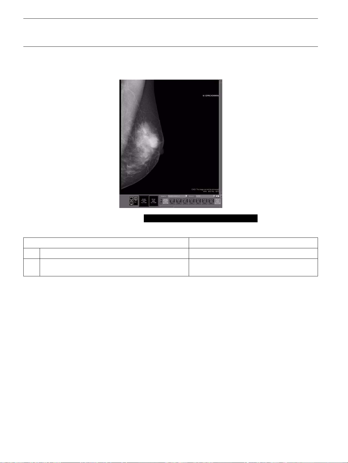
4-9-3. CAD: This image can not be processed . . . . . . . . . . . . . . . . . . . . . . . . . . . . 21
4-10. Printing CAD results . . . . . . . . . . . . . . . . . . . . . . . . . . . . . . . . . . . . . . . . . . . . . . . . . 22
4-11. Transferring the CAD overlay . . . . . . . . . . . . . . . . . . . . . . . . . . . . . . . . . . . . . . . . . . 22
4-12. Storing the CAD overlay . . . . . . . . . . . . . . . . . . . . . . . . . . . . . . . . . . . . . . . . . . . . . . 22
4-13. Access to historic CAD information. . . . . . . . . . . . . . . . . . . . . . . . . . . . . . . . . . . . . . 22
5. Specifications . . . . . . . . . . . . . . . . . . . . . . . . . . . . . . . . . . . . . . . . . . . . . . . . . . . . . . . . . 23
5-1. Technical Specifications . . . . . . . . . . . . . . . . . . . . . . . . . . . . . . . . . . . . . . . . . . . . . . 23
5-2. Equipment Labels and Symbols . . . . . . . . . . . . . . . . . . . . . . . . . . . . . . . . . . . . . . . . 24
5-2-1. Symbols . . . . . . . . . . . . . . . . . . . . . . . . . . . . . . . . . . . . . . . . . . . . . . . . . . . . . 24
5-2-2. APC UPS labels (rear panel) . . . . . . . . . . . . . . . . . . . . . . . . . . . . . . . . . . . . . 25
5-2-3. SLDU labels . . . . . . . . . . . . . . . . . . . . . . . . . . . . . . . . . . . . . . . . . . . . . . . . . . 26
6. Radiologist Training and SLD CAD Algorithm Descriptions . . . . . . . . . . . . . . . . . . . . . . 27
6-1. Overview . . . . . . . . . . . . . . . . . . . . . . . . . . . . . . . . . . . . . . . . . . . . . . . . . . . . . . . . . . 27
6-2. Second Look Digital in Breast Cancer Detection . . . . . . . . . . . . . . . . . . . . . . . . . . . 27
6-2-1. Background . . . . . . . . . . . . . . . . . . . . . . . . . . . . . . . . . . . . . . . . . . . . . . . . . . 27
6-2-2. Description of Second Look Digital . . . . . . . . . . . . . . . . . . . . . . . . . . . . . . . . 28
6-3. Second Look Digital Device Labeling . . . . . . . . . . . . . . . . . . . . . . . . . . . . . . . . . . . . 30
6-3-1. Brief Device Description . . . . . . . . . . . . . . . . . . . . . . . . . . . . . . . . . . . . . . . . 30
6-3-2. Indications for Use . . . . . . . . . . . . . . . . . . . . . . . . . . . . . . . . . . . . . . . . . . . . . 30
6-3-3. Contraindications . . . . . . . . . . . . . . . . . . . . . . . . . . . . . . . . . . . . . . . . . . . . . . 30
6-3-4. Warnings . . . . . . . . . . . . . . . . . . . . . . . . . . . . . . . . . . . . . . . . . . . . . . . . . . . . 31
6-3-5. Precautions . . . . . . . . . . . . . . . . . . . . . . . . . . . . . . . . . . . . . . . . . . . . . . . . . . 32
Table of Contents.fm
Page no. 7
Page 8

GE Healthcare Senographe SecondLook Digital CAD System
Revision 1 Operator Manual 5189820-5-C-1EN
Table of Contents
6-3-6. Adverse Effects . . . . . . . . . . . . . . . . . . . . . . . . . . . . . . . . . . . . . . . . . . . . . . . 33
6-3-7. Clinical Studies . . . . . . . . . . . . . . . . . . . . . . . . . . . . . . . . . . . . . . . . . . . . . . . 33
6-3-8. Principles of Operation . . . . . . . . . . . . . . . . . . . . . . . . . . . . . . . . . . . . . . . . . 38
6-3-9. Conformance to Standards . . . . . . . . . . . . . . . . . . . . . . . . . . . . . . . . . . . . . . 41
6-3-10. How Supplied . . . . . . . . . . . . . . . . . . . . . . . . . . . . . . . . . . . . . . . . . . . . . . . . 41
6-4. Radiologist Use of Second Look Digital . . . . . . . . . . . . . . . . . . . . . . . . . . . . . . . . . . 43
6-4-1. Radiologist Review Prior to Viewing CAD Marks . . . . . . . . . . . . . . . . . . . . . 43
6-4-2. Radiologist Review with CAD Marks . . . . . . . . . . . . . . . . . . . . . . . . . . . . . . . 43
6-5. Radiologist Training with Sample Cases . . . . . . . . . . . . . . . . . . . . . . . . . . . . . . . . . 45
6-5-1. Training Instructions . . . . . . . . . . . . . . . . . . . . . . . . . . . . . . . . . . . . . . . . . . . 45
6-5-2. Sample Cases . . . . . . . . . . . . . . . . . . . . . . . . . . . . . . . . . . . . . . . . . . . . . . . . 46
6-6. Summary of Radiologist Use of Second Look Digital . . . . . . . . . . . . . . . . . . . . . . . . 58
7. Actions to be taken in case of loss of power . . . . . . . . . . . . . . . . . . . . . . . . . . . . . . . . . . 61
7-1. Introduction . . . . . . . . . . . . . . . . . . . . . . . . . . . . . . . . . . . . . . . . . . . . . . . . . . . . . . . . 61
7-2. Loss of Mains power - On battery alarm . . . . . . . . . . . . . . . . . . . . . . . . . . . . . . . . . . 61
7-3. Low battery alarm . . . . . . . . . . . . . . . . . . . . . . . . . . . . . . . . . . . . . . . . . . . . . . . . . . . 61
7-4. UPS warnings and front panel . . . . . . . . . . . . . . . . . . . . . . . . . . . . . . . . . . . . . . . . . 61
8. Maintenance . . . . . . . . . . . . . . . . . . . . . . . . . . . . . . . . . . . . . . . . . . . . . . . . . . . . . . . . . . 62
8-1. Planned maintenance performed by the Radiologic Technologist . . . . . . . . . . . . . . 62
8-2. Planned maintenance performed by the Field Service Engineer . . . . . . . . . . . . . . . 62
Revision History . . . . . . . . . . . . . . . . . . . . . . . . . . . . . . . . . . . . . . . . . . . . . . . . . . . . . . . . . . 63
Page no. 8
Table of Contents.fm
Page 9

GE Healthcare Senographe SecondLook Digital CAD System
Revision 1 Operator Manual 5189820-5-C-1EN
1 Foreword
1-1 The Aim of This Manual
This manual is provided for operators using Senographe Acquisition Full Field Digital Mammography
(FFDM) systems equipped with the SecondLook Digital (SLD) Computer-Aided Detection (CAD) system
option.
It describes the flow of images and explains how to use the CAD options on the Acquisition Workstation
(AWS) and GE Healthcare the review workstations (RWS or Seno Advantage). It also provides
guidelines for the use of CAD in different situations, and information on problem solving.
This manual provides training information for radiologists, including descriptions of the SLD CAD
algorithms.
This manual does not contain information on CAD installation or configuration. Please refer to the
appropriate service manuals for information on these subjects.
This manual assumes that the reader is familiar with the Senographe Acquisition Workstation and the
GE Healthcare review workstations to be used.
1-2 Associated Operator Manuals
• Senographe Essential Acquisition System Operator Manual, 5307915-3-8991EN_r1 - Sirius M48
Technical Release.
• Senographe DS Acquisition System Operator Manual, 5307907-3-S-1EN_r1 - Nephtys M413
Technical Release.
• Senographe review workstation RWS Operator Manual, 2370487–100
• Senographe review workstation Seno Advantage Operator Manual, 5182593-4-S-1EN
CAD.fm
Page no. 9
Page 10

GE Healthcare Senographe SecondLook Digital CAD System
Revision 1 Operator Manual 5189820-5-C-1EN
1-3 Glossary
Terms used in this document:
Term Definition
AWS Acquisition workstation
RWS Senographe RWS review workstation
Seno Advantage Seno Advantage review workstation
CAD Computer-Aided Detection
SLD SecondLook Digital
SLDU SecondLook Digital Unit
CAD system A product composed of the SLDU and optional features on the AWS and the review
workstation
RAW FOR
PROCESSING
PROCESSED FOR
PRESENTATION
SCPT Secondary Capture Image
ROI Region(s) of Interest; questionable area of image (containing possible abnormalities
RTSS RadioTherapy Structure Set (DICOM object type)
CAD-analyzed image An image that has been successfully processed by the SLDU
CAD overlay Results produced by the SLDU and delivered to the review workstation. An overlay
CAD Marker A symbol (ellipse or rectangle) used in a CAD overlay to identify a region of interest.
CAD Label Information on a CAD overlay indicating the image status
CAD Identifier The part of a CAD label which indicates the CAD software version
Raw (original image produced by Image Detection Controller (IDC)
Processed (image processed by AWS computer)
which may require investigation)
consists of a
CAD label
(always) and
CAD markers
(as required).
Page no. 10
CAD.fm
Page 11

GE Healthcare Senographe SecondLook Digital CAD System
Revision 1 Operator Manual 5189820-5-C-1EN
2 CAD in mammography
2-1 What CAD can do
Detecting and diagnosing breast cancer is a complex clinical problem. The combination of viewing a
large number of cases (99.5% of which are expected to be non-cancerous in a screening population),
radiologist fatigue (and the resulting observational oversights), the complex image structure of the breast
on a mammogram, and the subtle nature of certain observational characteristics of the disease, may
result in false negative mammographic readings.
The SecondLook Digital Computer-Aided Detection system developed for use with GE’s Full Field Digital
Mammography system is designed to minimize observational oversights made by the radiologist.
Intended to be an aid for a radiologist reading routine screening and diagnostic mammograms,
SecondLook Digital identifies areas, or "regions of interest" (ROIs), on the digital image which show
features that may be associated with cancer, and may warrant a second review. These ROIs are brought
to the attention of the radiologist after he or she has completed normal interpretation of the digital
mammogram.
2-2 What CAD cannot do
It is important to note that CAD is not meant to be used for primary diagnosis. CAD is not meant to
replace the expertise of the radiologist. It is meant to be used as an
interpretive
mammogram images provided directly by the GE Senographe may be used for interpretation by the
radiologist. By design, the Senographe Review Workstations only allows the display of ROI markers
after the images are presented, free of markers, to the radiologist for his/her primary diagnostic
interpretation.
CAD is a highly sophisticated system, but it cannot identify all abnormalities. You should base your
interpretation upon the original mammogram images and use CAD only as an aid to detection.
Individual practice patterns may influence the results obtained when using this system. Therefore, each
facility and radiologist should carefully monitor the results that this device has on their practice of
mammography in order to optimize its effectiveness.
aid. CAD should be used only after the initial reading by the radiologist. Only the
aid to
detection
, and not as an
CAD.fm
Page no. 11
Page 12

GE Healthcare Senographe SecondLook Digital CAD System
Revision 1 Operator Manual 5189820-5-C-1EN
3 CAD Principles
The CAD system includes three sub-systems: the SecondLook Digital Unit (SLDU), the Review
Workstation (RWS or Seno Advantage ), and the Acquisition Workstation (AWS).
CAD processing functions are provided by the SLDU, a dedicated computer which runs the CAD
processing algorithms and generates the CAD results as an overlay. The review workstation displays the
overlay with the associated image.
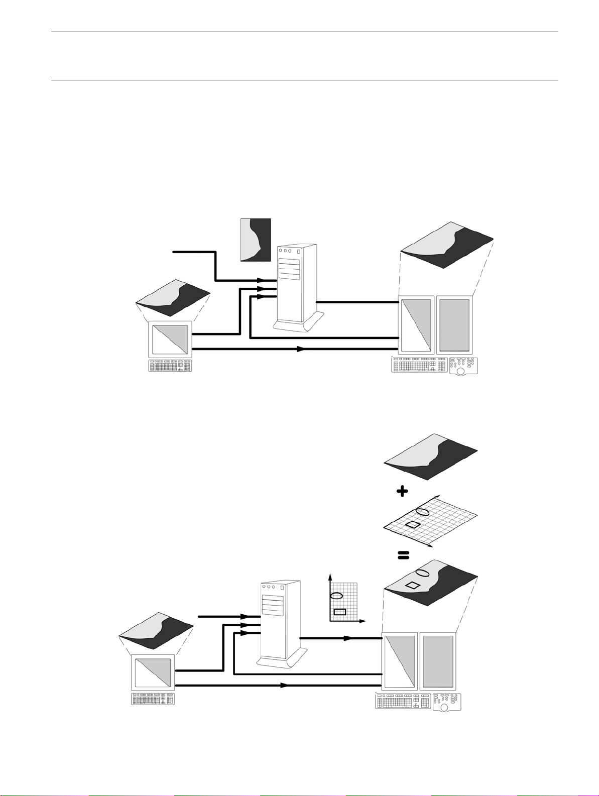
The CAD image workflow, illustrated below, includes three main steps:
1.
RAW images are pushed to the SecondLook Digital Unit (SLDU
workstation, or from an image storage system if present. Each image must have been produced by a
licensed workstation, declared in the CAD configuration. Images may be pushed individually or in
groups. Corresponding images (RAW or PROCESSED) from the AWS must also be pushed to the
review workstation before results can be viewed.
2.
The SLDU performs its analysis on each image
workstation in the form of a CAD overlay.
CAD processing of an image is not instantaneous. The SLDU takes an average of 30 seconds
(maximum 120 seconds) to process a 19 x 23 cm RAW image and generate a CAD overlay, or 2
minutes for a group of four images. Additional time may be required if there are multiple processing
requests.
3.
The
CAD
overlay is displayed with the associated images
and delivers the results of the analysis to the review
) from the AWS or the review
in the form of markers and labels.
Page no. 12
CAD.fm
Page 13
GE Healthcare Senographe SecondLook Digital CAD System
Revision 1 Operator Manual 5189820-5-C-1EN
CAD Image workflow
Step 1. The raw image is pushed to the SLDU for analysis.
The image (raw and/or processed) must also be pushed to the review workstation before CAD results can be
viewed.
The user first views the processed image on the review workstation without CAD markers.
Original (raw) image created by a
licensed AWS
Raw or processed
image
Image from storage or
archiving device (PACS,
RADSTORE, etc.)
AWS
Raw and/or processed images
Step 2. When the SLDU has performed its analysis on each image, it
sends an overlay to the review workstation, showing the location and
type of any regions of interest that were found.
Step 3. While viewing the image, the user presses the CAD button or
the U2 button on the dedicated keypad (if configured) to display the
CAD overlay.
SLDU
review monitors
Raw or processed
image
CAD overlay
CAD.fm
AWS
SLDU
CAD overlay
Raw and/or processed images
Page no. 13
Image displayed
with overlay
review monitors
Page 14

GE Healthcare Senographe SecondLook Digital CAD System
Revision 1 Operator Manual 5189820-5-C-1EN
4Using CAD
4-1 How do I know if CAD is available on this system?
4-2
When the CAD option is installed and operational, CAD icons are displayed in the Network
Panels of the AWS and review workstation Browser screens.RWSViewerAdvanced Card
CAD
On Demand/CAD Auto Push
CAD on demand (manual triggering of CAD analysis) is always available. CAD analysis of an image may
be requested whenever CAD evaluation is required, on a case-by-case basis . If you wish to use CAD
only from time to time for help in detecting abnormalities in individual questionable images, use CAD On
Demand.
CAD Auto Push may be configured at installation time, by the GE installation Engineer.
When CAD Auto Push is configured, CAD processing is applied automatically to all images as soon as
they are acquired by the AWS and pushed to the SLDU, so that the CAD information is systematically
available when reviewing the results on the review workstation. The CAD overlay, however, is not
displayed until after the original mammogram images generated by the Senographe (without CAD
markers) have been presented for interpretation by the radiologist.
Page no. 14
CAD.fm
Page 15

GE Healthcare Senographe SecondLook Digital CAD System
Revision 1 Operator Manual 5189820-5-C-1EN
4-3 Which images can be CAD-analyzed?
All images to be analyzed by the SLDU must have been generated on a licensed Senographe system.
The SLDU algorithm will analyze any raw (RAW) full breast mammographic image.
The following images cannot be analyzed:
• Processed (PROCESSED) and secondary capture (SCPT) images.
System performance is not assured for the following views:
• Segmented views of the breast.
• Implant views with the full implant imaged. Implant Displaced views with a maximum of 25 mm (1") of
breast implant imaged can be analyzed.
• Special diagnostic images (e.g., magnification views, or spot compression views).
• Cleavage views.
• Images with hook wires.
• Collimated images.
• Coned images.
4-4 Which image formats can be displayed with CAD markers?
The following image formats can be displayed with CAD markers:
• RAW images
• Processed images
• Premium View images, for users who have the Premium View Option on the review workstation.
4-5 Selecting images for CAD analysis
• You can choose to use CAD to process an individual image, a set of images, a series, or an entire
patient case.
•Only
• To obtain the best analysis of available information, send entire patient cases (rather than individual
• To minimize the elapsed time before CAD overlays are available, send only raw images.
raw
images can be CAD-processed. If you send an entire patient case to the SLDU, the raw
images are CAD-processed; other images present (processed or secondary-capture images) are
ignored, but increase the time required to obtain the overlays.
images) to be CAD-processed. The SLDU takes advantage of all available information during
analysis. If different views of the same breast are present, the SLDU uses all screening views in its
analysis, just as a clinician would.
However, note that this increases the time required to obtain the overlays; processing a 4-view exam
takes two minutes, as opposed to 30 seconds for a single view.
CAD.fm
Page no. 15
Page 16
GE Healthcare Senographe SecondLook Digital CAD System
Revision 1 Operator Manual 5189820-5-C-1EN
4-6 How are CAD overlays Displayed?
• Each image being viewed is displayed with its associated CAD overlay, if one exists. A
the bottom of each image gives its status. Refer to the following sections for more information:
CAD label Refer to
CAD label
at
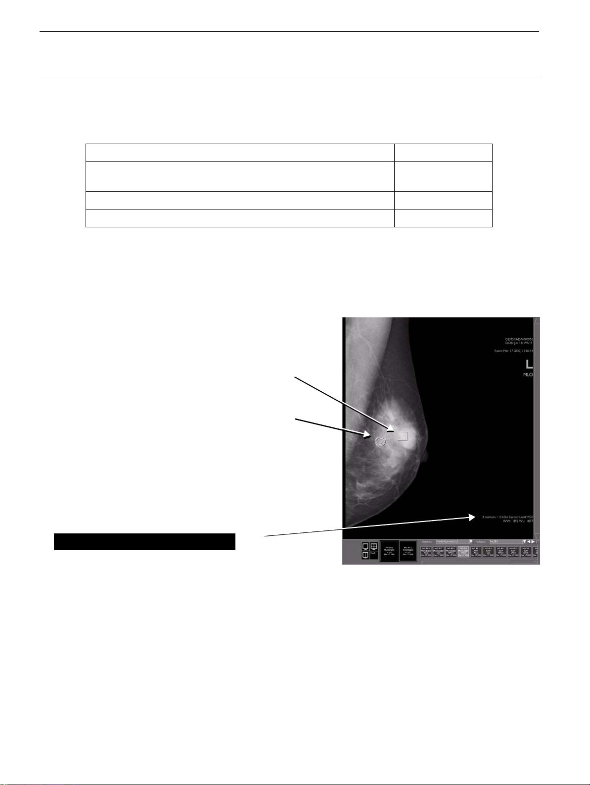
2 markers - iCAD SecondLook V7.2
This indicates that the image has been successfully analyzed.
CAD: Result not available Section
CAD: This image can not be processed: Section
Section
4-6-1
4-6-2
4-6-3
4-6-1 Image successfully analyzed
• If the image has been successfully analyzed, the CAD label is in the form
SecondLook V7.2.
It indicates the number of CAD markers present as well as the CAD software
2 markers - iCAD
version in use.
• When the SLDU identifies ROIs (regions of interest) on an image, the overlay includes a marker
to indicate each ROI:
SecondLook Digital CAD markers
The system uses two different markers to identify
ROIs for the radiologist's review:
• A rectangle surrounding a cluster of bright
spots, corresponding to a cluster of possible
microcalcifications.
• An ellipse surrounding a density with or
without radiating lines, corresponding to a
possible mass or architectural distortion.
CAD label with software identifier
2 markers - iCAD SecondLook V7.2:
• CAD markers are linked to specific points on the image and cannot be moved. Changing the
image orientation, zooming, drawing objects, adding text, etc. does not change the display of the
markers relative to the image; they move with the image as it is rotated.
Note:
CAD markers are automatically sized according to the size of the ROI.
Page no. 16
CAD.fm
Page 17
GE Healthcare Senographe SecondLook Digital CAD System
Revision 1 Operator Manual 5189820-5-C-1EN
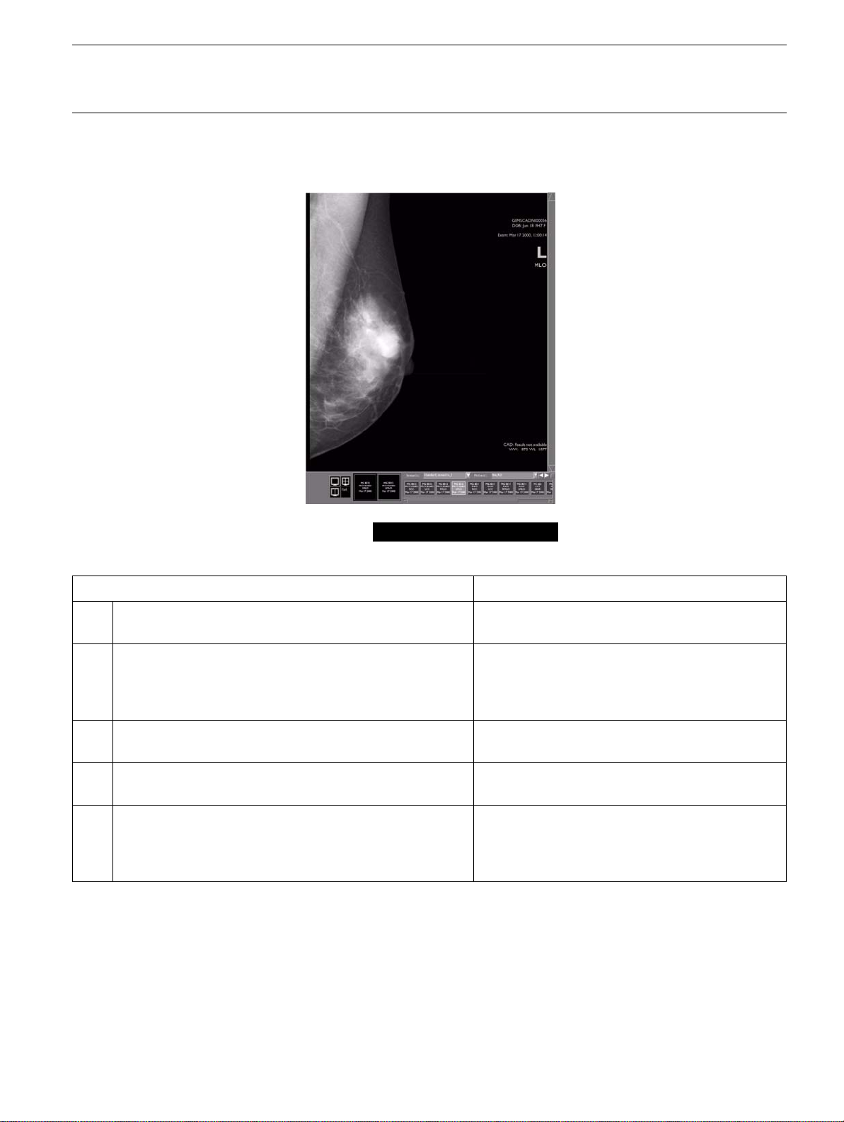
4-6-2 CAD: Result not available
The CAD label is: CAD: Result not available
Possible cause What to do
1. The image has not been submitted for analysis. Check for CAD overlays in the Browser lists;
push the image to the SLDU.
2. The CAD overlay is not yet available on the review
workstation because analysis has not been completed
(it takes an average of 30 seconds to process an image;
2 minutes for a 4-view exam).
3. The image was submitted for analysis but a transfer or
network failure occurred.
4. The CAD overlay has been removed from the review
workstation.
5. The CAD licence is not valid for the workstation which
created the image (this problem should be indicated by
a "
Network problem ....
the image(s) to the SLDU).
" message when trying to push
Wait for process completion.
Check for CAD overlays in the Browser lists;
push the image to the SLDU again.
Check for CAD overlays in the Browser lists;
push the image to the SLDU again.
Consult your GEMS Field Engineer
CAD.fm
Page no. 17
Page 18
GE Healthcare Senographe SecondLook Digital CAD System
Revision 1 Operator Manual 5189820-5-C-1EN
4-6-3 CAD: This image can not be processed
The CAD label is: CAD: This image can not be processed
Possible cause What to do
1. The image is not a type suitable for CAD processing Use a suitable type of image (see section
2. The CAD algorithm was unable to create an overlay
within the pre-determined time (normally 30 seconds).
Use another image of the same patient
4-3
).
Page no. 18
CAD.fm
Page 19

GE Healthcare Senographe SecondLook Digital CAD System
Revision 1 Operator Manual 5189820-5-C-1EN
4-7 Printing CAD results
• Make the CAD overlay visible and print the image using the Print screen option on the review
workstation. Any CAD markers and labels present are printed.
4-8 Transferring the CAD overlay
• The CAD overlay can be pushed to other Senographe review workstations. If the corresponding
images are also present on the workstation, the CAD results can be displayed.
4-9 Storing the CAD overlay
• The CAD overlay itself can be saved as an image of type RTSS.
• Displayed images (RAW, processed and Premium View) with CAD overlays can be stored as SCPT
images.
4-10 Access to historic CAD information
• If you may require access to CAD information at a later date (after current images have been deleted
from the system), there are two possibilities:
- Save images with associated CAD overlays as SCPT images.
- Save the raw images so that they can be processed again when required.
CAD.fm
Page no. 19
Page 20

GE Healthcare Senographe SecondLook Digital CAD System
Revision 1 Operator Manual 5189820-5-C-1EN
5 Specifications
5-1 Technical Specifications
Power Requirements ≤ 550 watts, 90/264 VAC, 50/60 Hz
Dimensions and weights
(approximate - may vary
according to the type of
processor )
Environmental - Temperature Operating temperature range: 5° to 40°C, non-operating temperature range: -
Environmental - Humidity Non-operating humidity: 35°C at 95% RH, non-condensing, over full
Environmental - Altitude Max operating altitude: 1500m
Signal connections 10/100/1000 Mb/s Base-T ethernet
Main unit (SLDU):
h 458 mm (18 in.), w 235 mm (9.25 in.), d 483 mm (19 in)
weight: 20.4 kg (45 lbs) without peripherals
40° to 70°C
temperature range
Page no. 20
CAD.fm
Page 21

GE Healthcare Senographe SecondLook Digital CAD System
Revision 1 Operator Manual 5189820-5-C-1EN
5-2 Equipment Labels and Symbols
5-2-1 Symbols
Protective ground (earth)
Ground (earth)
Dangerous voltage
Type B equipment
This symbol indicates that waste electrical and electronic equipment must not be disposed
of as unsorted municipal waste and must be collected separately. Please contact an
authorized representative of the manufacturer for information concerning the
decommissioning of your equipment.
This symbol indicates that the product contains hazardous materials in excess of the limits
established by the Chinese standard SJ/T11363-2006 (Requirements for Concentration
Limits for Certain Hazardous Substances in Electronic Information Products).
CAD.fm
Page no. 21
Page 22

GE Healthcare Senographe SecondLook Digital CAD System
Revision 1 Operator Manual 5189820-5-C-1EN
5-2-2 SLDU labels
WARNING
Connect only to a properly
earth grounded outlet.
PRODUCT CODE:
SERIAL NO.:
TOP ASSEMBLY NO.::
Page no. 22
CAD.fm
Page 23

GE Healthcare Senographe SecondLook Digital CAD System
Revision 1 Operator Manual 5189820-5-C-1EN
6 Radiologist Training and SLD CAD Algorithm Descriptions
6-1 Overview
This section is intended to describe the SecondLook Digital Computer-Aided Detection algorithms and
provide training to radiologists using the SecondLook Digital system in breast cancer detection.
• Section 6-2
SecondLook Digital in breast cancer detection.
• The SecondLook Digital Device Labeling is included in section 6-3
Labeling
warnings and precautions, adverse effects, summary of clinical studies, a description of the principles
of operation for the Computer-Aided Detection (CAD) algorithms, a list of conformance to standards,
and how the system is supplied.
• The procedures for a radiologist using the SecondLook Digital CAD marks are described in Section
6-4
Radiologist Use of SecondLook Digital
• Sample cases are provided in Section 6-5
radiologist with the SecondLook Digital system prior to clinical use.
• Section 6-6
SecondLook Digital.
SecondLook Digital in Breast Cancer Detection
gives an overview of the role of
SecondLook Digital Device
, which provides a brief description of the system, indications for use, contraindications,
.
Radiologist Training with Sample Cases
Summary of Radiologist Use of SecondLook Digital
summarizes a radiologist’s use of
to familiarize the
6-2 SecondLook Digital in Breast Cancer Detection
6-2-1 Background
SecondLook, a Computer-Aided Detection (CAD) system for mammography, has been developed by
iCAD, Inc. to identify and mark regions of interest on screening and diagnostic mammograms to bring
them to the attention of radiologists after the initial reading has been completed. Thus, the system
assists the radiologist in minimizing observational oversights by identifying areas on the original
mammogram that may warrant a second review. The SecondLook system was first developed for use
with screen-film mammography (SFM).
For SecondLook to process full-field digital mammography (FFDM) from the General Electric Medical
Systems (GEMS) Senographe, a new optional system component has been developed, SecondLook
Digital. SecondLook Digital can be configured as a stand-alone system that only processes FFDM.
In the U.S. in 2002, invasive breast cancer is expected to be newly diagnosed in 203,500 women, and an
additional 54,300 women will be diagnosed with in situ breast cancer. Therefore, breast cancer will be
the cause of death in 39,600 women in 2002, making it the second highest cause of cancer death in U.S.
women. The lifetime risk of a woman in the U.S. developing breast cancer has been estimated to be one
in nine.
Although recent analysis of the 8 randomized breast cancer screening trials has questioned the
reduction in mortality from screening with mammography
sponsored by the NCI (National Cancer Institute) concurred with this uncertainty
international organizations still affirm that screening with mammography and/or clinical breast
examination is effective in reducing breast cancer mortality. The USPSTF (U.S. Preventive Services
Task Force), sponsored by HHS (Health & Human Services), commissioned an evaluation of the 8
mammography screening trials and concluded that mammography reduces breast cancer mortality by
16%.
Health Organization), concluded that these randomized trials show that mammography reduces breast
cancer mortality by 25-35% in women aged 50-69 years.
1.
2.
and the PDQ (Physician Data Query) panel
3.
, other U.S. and
4.
The IARC (International Agency for Research on Cancer), which is part of the WHO (World
5.
CAD.fm
Page no. 23
Page 24

GE Healthcare Senographe SecondLook Digital CAD System
Revision 1 Operator Manual 5189820-5-C-1EN
The sensitivity of mammography ranges from 70% to 90%.6.,7.,8.,9.,
10.,11.,12.,13.
. Thus, for a woman with
breast cancer, there is about a 70% to 90% probability that her cancer will be detected by screening
mammography and a 10% to 30% probability it will not. Therefore, even though mammography is an
effective tool to detect breast cancer and reduce mortality, there is need for further improvement in
mammographic sensitivity.
Studies have shown that the accuracy of mammographic interpretation increases when a mammogram
is evaluated by 2 radiologists (double reading). Double reading improves breast cancer detection by 5%
to 15%.
standard of care and requires substantial additional resources, which are often not available.
14.,15.,16.,17.,18.,19.,20.,21.,22.,23.,24.,25.
However, double reading is not currently advocated as a
25.
A
cancer can be missed because it is not mammographically visible or because of an oversight or
misinterpretation. Clinical studies have shown that 30% to 70% of breast cancers diagnosed at
screening mammography are visible in retrospect on prior examinations, and that detection errors are
responsible for approximately half of missed breast cancers, with interpretation errors accounting for the
other half.
9.,26.,27.,28.,29.,30.,31.,32.,33.
.
In view of the frequency of missed cancers and of the lack of general support for double reading as a
standard of care, CAD of breast lesions on mammograms is a method to increase the sensitivity of
mammography and possibly further reduce breast cancer mortality. CAD in combination with review by
a single radiologist is an alternative to double reading for reducing the number of detection errors that
lead to missed breast cancers.
6-2-2 Description of SecondLook Digital
SecondLook Digital is a mammographic CAD system that identifies and highlights potential areas of
concern to assist radiologists in breast cancer detection. The CAD algorithms used in the SecondLook
Digital computer system include image processing, feature computations, and pattern recognition
technology to detect mammographic features indicative of malignancies. Areas of concern marked
include suspicious clusters of microcalcifications, spiculated and non-spiculated masses, architectural
distortions, and focal asymmetric densities. SecondLook Digital does not distinguish between benign
and malignant processes and may highlight technical artifacts.
SecondLook Digital integrates with the GEMS Senographe FFDM system to process FFDM images.
The resulting CAD marks are typically displayed overlying the appropriate locations of the mammogram
on the review workstation used by the radiologist for softcopy reading. When the CAD marks are
displayed within the review workstation, the radiologist can turn on or off the display of CAD marks
overlying the mammogram. Although the remainder of this manual is written with the assumption that
the CAD marks are viewed on a review workstation, a paper printout of the CAD marks is another
possible option. The radiologist using a paper printout follows similar procedures.
Typical screening mammography includes four mammographic views: left and right craniocaudal
projections (L-CC and R-CC) and left and right mediolateral oblique projections (L-MLO and R-MLO).
SecondLook Digital assists radiologists with these mammographic views and full-breast diagnostic
views. On occasion, other views are obtained for screening or diagnostic purposes, such as left and
right exaggerated craniocaudal projections rotated laterally (L-XCCL and R-XCCL) and left and right
straight mediolateral projections (L-ML and R-ML). When additional screening or diagnostic views are
taken, SecondLook Digital may process more than 4 views for each patient. SecondLook Digital is not
used to assist the radiologist in evaluating magnification/compression views or specimen radiography.
For patients with breast implants, SecondLook Digital is used with implant-displaced views only. When
SecondLook Digital processes magnification/compression views, specimen radiography, or nondisplaced implant views, any resulting CAD marks should not be used by the radiologist in evaluating the
patient.
Page no. 24
CAD.fm
Page 25

GE Healthcare Senographe SecondLook Digital CAD System
Revision 1 Operator Manual 5189820-5-C-1EN
SecondLook Digital is intended to be used by a radiologist as follows: The radiologist must first review
the mammogram in the normal manner and only afterward consult the CAD marks to determine if
SecondLook Digital has marked any areas of concern that were not observed on the initial review. To
view the CAD marks prior to the initial unassisted review of the mammogram risks the so-called
satisfaction-of-search error, in which the radiologist’s vigilance for other areas on the mammogram may
be lowered by virtue of seeing one or more areas highlighted by SecondLook Digital. The absence of a
CAD mark at a lesion initially detected without the assistance of SecondLook Digital should not be used
by the radiologist to override the decision to further evaluate the lesion.
SecondLook Digital is designed to mark areas with the mammographic appearance of cancer; however,
many of the marked areas will not contain a malignancy, and it is up to the radiologist to decide, using
conventional clinical judgment and reviewing the mammogram itself, if the area is suspicious enough to
warrant further work-up. SecondLook Digital is not a diagnostic device, as the CAD marks are intended
to be used to assist only in detection and not in interpretation. Therefore, SecondLook Digital can assist
a radiologist in detecting areas of concern that would have been missed without its use, but used
properly it cannot cause a radiologist to miss areas of concern that would have been detected without
SecondLook Digital.
SecondLook Digital was developed by leaders in the fields of image processing and artificial intelligence.
Below is a description of how SecondLook Digital’s Computer-Aided Detection (CAD) works.
1. The GEMS Senographe full-field digital mammograms are processed by the system. Image
processing is used to identify all the potential cancerous locations in the image.
2. These locations are analyzed using radiologic and proprietary measures as well as a feature
selection process to determine the most likely locations to be cancer.
3. The most likely locations are evaluated in the context of the patient, and highlighted with CAD marks
displayed overlying the mammograms on the review workstation used by the radiologist for softcopy
reading.
It is important to remember that SecondLook Digital will not necessarily mark what a radiologist would
work-up. This is an important consideration as every radiologist works-up different areas based on her
or his own criteria.
SecondLook Digital does not function on its own, but always with a radiologist. Therefore, if SecondLook
Digital highlights a mass or microcalcifications in one view only, the radiologist can look for it in the other
view to determine if there is a lesion that warrants work-up.
CAD.fm
Page no. 25
Page 26

GE Healthcare Senographe SecondLook Digital CAD System
Revision 1 Operator Manual 5189820-5-C-1EN
6-3 SecondLook Digital Device Labeling
6-3-1 Brief Device Description
SecondLook is a mammographic Computer-Aided Detection (CAD) system that identifies and highlights
potential areas of concern to assist radiologists in breast cancer detection. The CAD algorithms used in
the SecondLook computer system include image processing, feature computations, and pattern
recognition technology to detect mammographic features indicative of malignancies. Areas of concern
identified include suspicious clusters of microcalcifications, spiculated and non-spiculated masses,
architectural distortions, and focal asymmetric densities.
SecondLook integrates with the GEMS Senographe full-field digital mammography system to process
these full-field digital mammography images. Suspicious clusters of microcalcifications are marked with
CalcMarks, while suspicious spiculated and non-spiculated masses, architectural distortions, and focal
asymmetric densities are marked with MassMarks. These CAD marks are typically displayed overlying
the appropriate locations of the GEMS Senographe full-field digital mammography images within the
review workstation used by the radiologist for softcopy reading. A paper printout of the CAD marks is
another possible option.
SecondLook is intended to be used by a radiologist as follows: The radiologist must first review the
mammogram in the normal manner and only afterward consult the CAD marks to determine if
SecondLook has marked any areas of concern that were not observed on the initial review. SecondLook
is designed to mark areas with the mammographic appearance of cancer; however, many of the marked
areas will not contain a malignancy, and it is up to the radiologist to decide, using conventional clinical
judgment and reviewing the mammogram itself, if the area is suspicious enough to warrant further workup. SecondLook is not a diagnostic device, as the CAD marks are intended to be used to assist only in
detection and not in interpretation. The system design and its clinical use are compatible with the
Mammography Quality Standards Act of 1992 (MQSA).
6-3-2 Indications for Use
The SecondLook Digital Computer-Aided Detection system for mammography is intended to identify and
mark regions of interest on screening and diagnostic mammograms from the General Electric Medical
Systems Senographe full-field digital mammography system to bring them to the attention of the
radiologist after the initial reading has been completed. Thus, the system assists the radiologist in
minimizing observational oversights by identifying areas on the original mammogram that may warrant a
second review.
6-3-3 Contraindications
There are no contraindications for use of this device.
Page no. 26
CAD.fm
Page 27

GE Healthcare Senographe SecondLook Digital CAD System
Revision 1 Operator Manual 5189820-5-C-1EN
6-3-4 Warnings
6-3-4-1 Warnings: Radiological Interpretation
• The SecondLook system assists in breast cancer detection, not interpretation or diagnosis.
• Upon re-evaluation of the GEMS Senographe full-field digital mammography images at the locations
of the CAD marks, the radiologist uses interpretive skills to determine if the area should be workedup based on its mammographic appearance.
WARNING
The initial, unassisted review of GEMS Senographe full-field digital mammography images is
critical, because the system will not highlight all areas that the radiologist may detect, and using
the system before finishing the unassisted conventional image review runs the risk of inducing a
so-called satisfaction-of-search error, in which the radiologist fails to examine the unmarked
areas of the images with adequate vigilance.
- The system is not designed to highlight interval change between mammographic exams.
- The system is not designed to highlight asymmetric breast tissue, tubular density/solitary
dilated duct, skin thickening, or nipple retraction.
WARNING
The SecondLook system will highlight areas that a radiologist determines do not require work-up.
Thus, the work-up is determined by the radiologist, and the presence of a CAD mark should not
influence the decision that would have been made had the area been noted in the first place.
- The radiologist must still use diagnostic skills to differentiate benign from malignant lesions by
working-up the area, which may include magnification/compression mammography,
ultrasound, or interventional procedures.
WARNING
Therefore, the radiologist’s work-up decision should not be altered if the system fails to mark an
area that the radiologist has detected on the initial image review and has already decided
requires further work-up. Nor should the decision be affected if the system marks an area that
the radiologist decides is not suspicious enough to warrant further work-up, whether the area is
detected by the radiologist on initial image review or only after being marked by the system.
• Effectiveness and safety have not been established for non-standard mammographic views (e.g.,
magnification/compression views) or non-displaced implant views. Therefore, any CAD marks in
these views should not be used by the radiologist in evaluating the patient.
6-3-4-2 Warnings: System Operation
• The system should not be used if it is suspected that any electrical component is defective or
inoperable.
• Do not place any liquids on or near SecondLook. If a liquid is accidentally spilled on electrical
components, immediately turn off the SecondLook Digital Unit, which will automatically shut down the
system to prevent any potential electrical shock. Contact your authorized SecondLook service
provider for further instructions.
• Ensure that the system is connected to a properly wired and grounded power receptacle. Confirm
that the voltage and current requirements are within system specifications to avoid bodily injury from
electrical shock or fire hazard.
CAD.fm
Page no. 27
Page 28

GE Healthcare Senographe SecondLook Digital CAD System
Revision 1 Operator Manual 5189820-5-C-1EN
WARNING
6-3-5 Precautions
6-3-5-1 Precautions: System Operation
• To prevent damage to the system, maintain equipment in a well-ventilated, air-conditioned
environment.
• Only images from a GEMS Senographe full-field digital mammography system that is maintained in
accordance with MQSA standards should be used.
• Effectiveness and safety in patients with breast implants has not been established for views that
include the implant. When non-implant-displaced views are analyzed by the system, any resulting
CAD marks should not be used by the radiologist in evaluating the patient.
• Effectiveness and safety have not been established for non-standard mammographic views (e.g.,
magnification/compression views). When these views are analyzed by the system, any resulting
CAD marks should not be used by the radiologist in evaluating the patient.
6-3-5-2 Precautions: Installation and Maintenance
• This product contains no independently user serviceable parts. To prevent damage to the system, do
not attempt to install or repair the SecondLook system. Only trained personnel are qualified to install
or repair the system. For service training, contact iCAD, Inc. at 1-866-280-2239.
• Disconnect power cord before moving or servicing.
Page no. 28
CAD.fm
Page 29

GE Healthcare Senographe SecondLook Digital CAD System
Revision 1 Operator Manual 5189820-5-C-1EN
6-3-6 Adverse Effects
The use of SecondLook adds no known additional risks to mammography. There is no direct contact with
the patient.
6-3-7 Clinical Studies
Four comprehensive studies, ROSE-1, ROSE-S1, ROSE-DS, and ROSE-2, were conducted to evaluate
the use of the Second Look system by radiologists for breast cancer detection. ROSE-1, ROSE-S1, and
ROSE-2 evaluated the Second Look Analog system, while ROSE-DS assessed SecondLook Digital.
Second Look Analog is indicated for use with screen-film mammography, while SecondLook Digital uses
GEMS Senographe full-field digital mammography as input.
CAD.fm
Page no. 29
Page 30

GE Healthcare Senographe SecondLook Digital CAD System
Revision 1 Operator Manual 5189820-5-C-1EN
ROSE-1 and ROSE-S1
The first pivotal study, ROSE-1, was a multi-institutional trial to assess Second Look Analog as an aid for
radiologists in detecting breast cancer with screen-film mammography. A first supplemental study,
ROSE-S1, used digitized images obtained during the ROSE-1 study to evaluate updated software in
Second Look Analog. There were 4 components: the Missed Cancer Study assessed the percentage of
cancer cases missed by a radiologist that would be detected and worked-up with use of the system; the
Screen-Detected Study assessed the sensitivity of the system in detecting cancers on mammograms
that led to the diagnosis of breast cancer; the Reproducibility Study assessed the reproducibility of the
system’s markings; and the Normal Study assessed the false positive rate of the system.
Missed Cancer Study
The Missed Cancer Study assessed the number of previously overlooked cancers that would have been
detected and worked-up by the radiologist if using SecondLook. Seventeen (17) institutions enrolled 374
screening mammography cases that were originally interpreted as normal or benign within 9 to 24
months prior to the screening mammogram that led to cancer diagnosis. These 374 cases had both the
current and prior mammograms available for analysis. The 374 prior mammograms underwent
independent, blinded review by 3 radiologists (the panel) for detection and recommendation of work-up
of mammographic abnormalities. At least one of the panel radiologists recommended work-up in 310
cases, while the other 64 cases were not recommended for work-up by any of the panel. Of the 310
cases, 174 had one or more work-ups confirmed to be at the locations of subsequently diagnosed
cancers by 2 other (truthing) radiologists. The truthing radiologists worked independently of each other
and were required to reach a consensus over initial disagreements. They worked unblinded, with the
help of the subsequent mammogram that led to the diagnosis of cancer.
Of these 174 previously missed cancers, approximately 66% were represented primarily by "masses"
and 34% by microcalcifications. The "masses" included spiculated and non-spiculated masses,
architectural distortions, and asymmetric densities. The digitized images of these 174 mammograms
were then processed by SecondLook. The locations of the MassMarks and CalcMarks were compared
to the locations of the subsequently diagnosed cancers. This process measured the sensitivity of the
SecondLook system in detecting missed cancers. To assess the effect of the system in actual clinical
practice, it is necessary to account for the likelihood that a radiologist would indeed work-up a region
marked by SecondLook. To accomplish this, the proportion of blinded panel radiologists correctly
identifying each missed cancer case was used as a likelihood multiplier. Since there were three panel
radiologists, this proportion was 0/3, 1/3, 2/3, or 3/3. Use of this proportional weighting resulted in a
lower bound for the number of cases that showed actionable signs of cancer on the prior mammograms
that were originally interpreted as normal or benign, for the following reason. The panel radiologists who
failed to identify a region could have failed on the basis of either an error of detection or an error of
interpretation, but the distribution of cases between these two types of errors was not recorded. So it
was simply assumed that all lesions had been detected by all three of the unaided panelists and that
failures to recommend work-up were due strictly to errors of interpretation. Thus, multiplying by 0/3, 1/3,
etc. results in the most conservative estimate of the system’s effectiveness as an aid to a radiologist in
detecting breast cancer.
By this method it was determined that of these 174 missed cancer cases, 121.3 (69.7%) were
actionable. Of these actionable cases, at least 86.0 (70.9%) were marked by SecondLook and would
have been worked-up if they had been pointed out to the clinical radiologist.
Page no. 30
CAD.fm
Page 31

GE Healthcare Senographe SecondLook Digital CAD System
Revision 1 Operator Manual 5189820-5-C-1EN
Retrospective review of the 310 cases by the truthing radiologists showed that 239 had retrospectively
visible lesions in the location of the subsequent cancer and 71 did not. These 239 cases included 174
cancers that at least one of the three panel radiologists deemed actionable plus 65 which none on the
panel deemed actionable. As a conservative estimate, all 64 of the cases not submitted to the truthing
radiologists for determination of lesion visibility were arbitrarily assumed to have retrospectively visible
lesions. Using this assumption, the maximum number of retrospectively visible missed cancer cases is
303 (239 + 64). Therefore, the reduction in retrospectively visible missed cancers with the use of
SecondLook is at least 28.4% (86.0/303). With a 95% confidence interval of 23.4% to 33.7%, this
conservative estimate of a 28.4% reduction in retrospectively visible missed cancers is clinically
significant.
The ability of a radiologist using SecondLook to detect cancer cases earlier than when they were
diagnosed by the original site radiologists was also assessed. The method used all 374 cancer cases
that were originally interpreted as normal or benign, instead of the subset of cases with retrospectively
visible lesions. The percent detected earlier was calculated as 23.0% (86.0/374) with a 95% CI of 19.0%
to 27.3%. Therefore, this retrospective study of 374 cancer cases showed that 23.0% (95% CI, 19.0% -
27.3%) of women diagnosed with breast cancer, who had prior screening mammograms within 9 24 months of diagnosis, could have had their cancers discovered earlier, by an average of 15.1 months,
with the use of SecondLook.
Screen-Detected Study
The Screen-Detected Study examined the sensitivity of SecondLook in detecting diagnosed cancers on
screening mammograms. Seventeen (17) institutions enrolled 906 subjects with screening
mammograms that led to the diagnosis of breast cancer (67% of which were represented primarily by
masses and 33% by calcifications). The digitized images of these 906 mammograms were processed
by SecondLook. The system correctly marked the cancer in 809 of these 906 cases. Thus, SecondLook
had a sensitivity of 89% for screen-detected cancer cases. The system sensitivity for clustered
microcalcifications was 95% (280/296) and 87% (529/610) for spiculated and non-spiculated masses,
architectural distortions and focal asymmetric densities.
Reproducibility Study
The Reproducibility Study evaluated the reproducibility of the SecondLook system. Digitized images of
25 screen-detected cancer cases from the Screen Detected Study were processed 10 times through
each of 3 SecondLook systems. The SecondLook system correctly marked the lesion in all cases.
Therefore, the SecondLook system reproducibility was 100% for correctly marked cancers.
Normal Study
The Normal Study assessed the false positive rate of SecondLook with 153 normal cases. The mean
numbers of total marks, MassMarks, and CalcMarks per case was 2.94, .2.29, and 0.65 for SecondLook.
The median numbers of total marks, MassMarks, and CalcMarks per case were 3, 2, and 0 for
SecondLook.
CAD.fm
Page no. 31
Page 32

GE Healthcare Senographe SecondLook Digital CAD System
Revision 1 Operator Manual 5189820-5-C-1EN
ROSE-2
The second pivotal study, ROSE-2, was a multi-institutional prospective trial designed to show that the
use of the original Second Look Analog system did not appreciably increase the number of suspicious
regions recommended for further work-up by radiologists reading screening mammograms. The workup rates of radiologists were prospectively determined before and after the use of SecondLook. In
addition, the interpreting radiologists estimated the additional time associated with the use of
SecondLook as a percentage of total reading time.
Ten (10) experienced mammographers at 5 institutions prospectively interpreted a total of 3,946
sequential screening mammograms. Each mammogram was then processed by SecondLook, and the
same radiologist then re-evaluated the mammogram with the CAD marks. Of the 3,946 cases, 657 were
recommended for work-up by radiologists before the use of SecondLook. After the use of SecondLook
an additional 20 cases were recommended for work-up, for a total of 677 cases. Therefore, the work-up
rate of radiologists was 16.6% (657 of 3,946) before use of SecondLook and 17.2 % (677 of 3,946)
afterward. The 95% confidence intervals for these work-up rates were (15.5% - 17.8%) before
SecondLook use and (16.0% - 18.4%) with it. This demonstrated that the 0.5% (20 of 3,946) increase in
work-up rate due to the use of SecondLook was insignificant.
In 3,631 of 3,946 prospective cases (92%) the estimated additional reading time to use SecondLook was
20% or less.
In addition, historical work-up rates for the same radiologists in the months prior to the prospective cases
were compared to their rates before the use of SecondLook to illustrate the variability inherent in the
process of reading screening mammograms. For this study, work-up included additional mammographic
views, short-interval follow-up, ultrasound, other advanced imaging modalities, or recommendation for
biopsy. Of the 3,876 historical cases, 516 were worked-up by radiologists without the use of
SecondLook for a 13.3% historical work-up rate. The 95% confidence interval on this work-up rate was
(12.3% - 14.4%). Thus, there was no overlap in the confidence intervals between the historical work-up
rate and the work-up rate prior to use of SecondLook compared to the considerable overlap of
confidence intervals between the work-up rates before and after SecondLook use. Consequently, the
inherent variability in radiologist work-up rates was larger than the increase due to the use of
SecondLook. This adds further evidence that the increase in work-up rate due to the use of SecondLook
is insignificant.
Page no. 32
CAD.fm
Page 33

GE Healthcare Senographe SecondLook Digital CAD System
Revision 1 Operator Manual 5189820-5-C-1EN
ROSE-DS
The second supplemental study, ROSE-DS, was conducted to assess the performance of SecondLook
Digital. An original PMA and a PMA supplement for the Second Look Analog system were previously
approved by the FDA’s Office of Device Evaluation for use with screen-film mammography. For
SecondLook to process GEMS Senographe full-field digital mammography, a new optional system
component was developed, SecondLook Digital.
SecondLook Digital and Second Look Analog were developed with common Computer-Aided Detection
algorithms for the system performance with GEMS Senographe full-field digital mammography and
screen-film mammography to be consistent. In the ROSE-DS study, the performance of SecondLook
Digital was assessed with 45 GEMS Senographe full-field digital mammography cancer cases and
compared to the Screen-Detected Study and Normal Study from ROSE-S1, which assessed the
performance of Second Look Analog with screen-film mammography from 906 screen-detected cancer
cases and 153 normal cases.
The results of the ROSE-DS study showed that the sensitivity of SecondLook Digital on GEMS
Senographe full-field digital mammography cases was statistically no different than the sensitivity of
Second Look Analog on screen-film mammography cases, while the false positive rate of SecondLook
Digital (2.03 false positive marks per case) was statistically improved from the false positive rate of
Second Look Analog (2.94 false positive marks per case). Thus, the results indicate that the
enhancement of a radiologist’s effectiveness in detecting breast cancer with SecondLook Digital with
input from a the GEMS Senographe full-field digital mammography system will at least be statistically no
different than the enhancement demonstrated with Second Look Analog.
Conclusions drawn from the studies:
• The use of the Second Look Analog system led to a clinically significant reduction in missed cancers
of at least 28.4% (95% CI 23.4% - 33.7%).
• A retrospective study of 374 cancer cases showed that 23.0% (95% CI, 19.0% - 27.3%) of women
diagnosed with breast cancer, who had prior screening mammograms within 9 - 24 months of
diagnosis, could have had their cancers discovered earlier, by an average of 15.1 months, with the
use of Second Look Analog.
• The use of the Second Look Analog system led to an insignificant increase in the number of workups recommended by radiologists reading screening mammograms from 16.6% (95% CI 15.5% -
17.8%) unaided to 17.2% (95% CI 16.0% - 18.4%) aided by the system.
• The sensitivity of SecondLook Digital with input from the GEMS Senographe full-field digital
mammography system was statistically no different than the sensitivity of Second Look Analog with
input from screen-film mammography.
• The false positive rate of SecondLook Digital with input from the GEMS Senographe full-field digital
mammography system was statistically improved from the false positive rate of Second Look Analog
with input from screen-film mammography, with a reduction in false positive marks per case from
2.94 with Second Look Analog to 2.03 with SecondLook Digital.
• The study with SecondLook Digital did not assess the impact of this system on reduction in missed
cancers, percent of women who could have had their cancers discovered earlier, and work-up rate.
In summary, the SecondLook system will enhance a radiologist’s effectiveness in detecting breast
cancer.
CAD.fm
Page no. 33
Page 34

GE Healthcare Senographe SecondLook Digital CAD System
Revision 1 Operator Manual 5189820-5-C-1EN
6-3-8 Principles of Operation
SecondLook uses Computer-Aided Detection (CAD) algorithms to identify suspicious lesions in
mammograms. The GEMS Senographe full-field digital mammography system creates digital
mammographic images that are input to SecondLook, and these CAD algorithms use advanced image
processing, feature computations, and pattern recognition technology to analyze the images for potential
areas of concern. These potential areas of concern are displayed for the radiologist by overlying CAD
marks at the appropriate locations of the GEMS Senographe full-field digital mammography images
within the softcopy review workstation or on a paper printout. The CAD marks are used by the
radiologist as an additional tool in breast cancer detection.
An overview of the SecondLook CAD algorithms is shown in
Standard
Mammography
Images
Illustration 1
.
MicroCalc
Algorithm
Calc Image
Enhancement
MicroCalc
Detector
Clustering
MicroCalc
Classifier
Density
Algorithm
Density Image
Enhancement
Density
Detector
Region
Growing
Density
Classifier
Context Based
Patient Evaluation
Areas of Concern
Highlighted by
CAD Marks
Illustration 1 SecondLook CAD Algorithms Overview
Page no. 34
CAD.fm
Page 35

GE Healthcare Senographe SecondLook Digital CAD System
Revision 1 Operator Manual 5189820-5-C-1EN
The CAD algorithms begin with image enhancement of the digitized mammographic images to
accentuate all areas that could be individual microcalcifications and densities. The microcalcification and
density detectors then identify the areas that are most likely to be individual microcalcifications and
densities, based on an initial analysis of morphological and intensity measurements. The types of
densities detected are depicted in
Illustration 2
and include spiculated and non-spiculated masses,
architectural distortions, and focal asymmetric densities.
Circumscribed Masses
LobularOvalRound
Obscured MassMicrolobulated Mass
Architectural DistortionSpiculated Mass
Irregular Mass with
Indistinct Margins
Illustration 2 Densities Detected by SecondLook
Note:
Focal asymmetric densities are difficult to depict pictorially, but are detected by SecondLook.
CAD.fm
Page no. 35
Page 36

GE Healthcare Senographe SecondLook Digital CAD System
Revision 1 Operator Manual 5189820-5-C-1EN
Further analysis of detected areas is accomplished by clustering individual microcalcifications and region
growing densities. Clusters include 3 or more individual microcalcifications that are each no more than
4.1 millimeters apart.
Illustration 3
depicts portions of three different GEMS Senographe full-field digital
mammography images showing how the SecondLook system would highlight microcalcifications clusters
in these examples. Note that t These examples use CAD marks that are rectangular and correspond to
the approximate size of the microcalcifications, although alternative symbols for the CAD marks may be
used. Region growing determines the shape of potential densities as shown in
Illustration 4
.
CalcMarks Highlighting Microcalcifications Clusters
c)
4.1 mm
a)
4.1 mm
b)
Where:
a. The minimum number of calcifications
b. The extent of the CalcMark enclosing all calcifications considered as part of the cluster
c. Overlapping CalcMarks are distinctly highlighted even when clusters are close to each
other
Illustration 3 Region Growing to Determine Shape of Density
After clustering for microcalcifications analysis and region growing for density analysis, clinically relevant
and mathematical features are then computed to describe each detected cluster of microcalcifications
and density. For example, the variability in size and shape of the calcifications in a cluster are good
features to describe clusters of microcalcifications. These features are used by microcalcifications and
density classifiers, which are specifically designed to select the areas most likely to be cancer.
Further analysis uses the context of all areas selected for the patient. For example, there is a maximum
total number of SecondLook CAD marks each 4-image case can include. Simultaneous analysis of all
areas of concern detected in the patient allows the locations most likely to be cancer to be highlighted by
the CAD marks.
Page no. 36
CAD.fm
Page 37

GE Healthcare Senographe SecondLook Digital CAD System
Revision 1 Operator Manual 5189820-5-C-1EN
Illustration 4 Region Growing to Determine Shape of Density
6-3-9
•
CAD.fm
Page no. 37
Page 38

GE Healthcare Senographe SecondLook Digital CAD System
Revision 1 Operator Manual 5189820-5-C-1EN
This page is intentionally left blank.
Page no. 38
CAD.fm
Page 39

GE Healthcare Senographe SecondLook Digital CAD System
Revision 1 Operator Manual 5189820-5-C-1EN
6-4 Radiologist Use of SecondLook Digital
6-4-1 Radiologist Review Prior to Viewing CAD Marks
The radiologist first reviews the GEMS Senographe full-field digital mammograms without viewing the
SecondLook Digital CAD marks, following her or his existing procedures of clinical practice. The
radiologist will make an initial determination if a work-up is indicated for the patient prior to turning on and
viewing the CAD marks with the softcopy review workstation.
6-4-2 Radiologist Review with CAD Marks
The radiologist turns on and views the SecondLook Digital CAD marks with the softcopy review
workstation after determining whether or not a work-up is indicated from her or his initial review of the
patient mammograms. The radiologist will "take a second look" at the mammograms corresponding to
any CAD marks. From this re-evaluation of the mammograms, the radiologist determines if any
additional work-up is required. If there are no CAD marks, no re-evaluation of the mammograms is
necessary. Work-up decisions are not based solely upon the CAD marks. All work-up decisions are
based upon review of the mammograms, supporting clinical information, and CAD marks by the
radiologist.
Areas of concern marked by SecondLook Digital include suspicious clusters of microcalcifications,
spiculated and non-spiculated masses, architectural distortions, and focal asymmetric densities. The
usefulness of CAD marks for the radiologist is due to the synergy between radiologist and SecondLook
Digital. SecondLook Digital is expected to mark some lesions that were initially overlooked on the
radiologist’s first review of the mammograms. Conversely, SecondLook Digital may not mark some
lesions detected by the radiologist. In other words, the radiologist may detect some lesions that
SecondLook Digital does not mark, and SecondLook Digital may mark some lesions that the radiologist
does not detect.
to detect more breast cancers than a radiologist alone or SecondLook Digital alone. Consequently, for
the use of SecondLook Digital to increase the sensitivity of mammography, it is particularly important for
the radiologist to review the mammograms prior to turning on and viewing the CAD marks with the
softcopy review workstation.
Illustration 5
demonstrates that a radiologist routinely using SecondLook Digital is likely
Illustration 5
CAD.fm
A
B
A: Detectable Breast Cancer.
B: Cancers Detected by a Radiologist.
C: Cancers Detected by SecondLook Digital.
Page no. 39
C
Page 40

GE Healthcare Senographe SecondLook Digital CAD System
Revision 1 Operator Manual 5189820-5-C-1EN
Below is the recommended case review process with SecondLook Digital
1. Review patient history and evaluate GEMS Senographe full-field digital mammograms prior to
turning on and viewing CAD marks with softcopy review workstation
2. Make initial interpretation
3. Turn on and view CAD marks with softcopy review workstation and identify potential areas of concern
4. Review mammograms, re-evaluating areas of concern highlighted by CAD marks with softcopy
review workstation
5. Render decision
It is very important to remember that it is the radiologist who makes the final decision about a case.
When a radiologist decides to work-up a case, the CAD marks must not change the decision; however,
the CAD marks can identify locations for further work-up that were initially undetected by the radiologist.
Page no. 40
CAD.fm
Page 41

GE Healthcare Senographe SecondLook Digital CAD System
Revision 1 Operator Manual 5189820-5-C-1EN
6-5 Radiologist Training with Sample Cases
6-5-1 Training Instructions
Three sample cases demonstrate the use of SecondLook Digital for the radiologist prior to clinical use.
These cases are intended to familiarize the radiologist with the procedures for using the SecondLook
Digital CAD marks. The case review procedures are emphasized. Therefore, the training is
accomplished by following the case presentations in Section 6-5-2
requiring use of the softcopy review station.
For each case in the manual, the procedures for using SecondLook Digital CAD marks are
demonstrated to the radiologist with the following steps:
1. The first page will provide the case history and printed versions of the GEMS Senographe full fielddigital mammograms without CAD marks. During clinical use, the radiologist would first review the
mammograms without viewing the CAD marks, following her or his existing procedures of clinical
practice. The radiologist would make an initial determination if a work-up were indicated for the
patient prior to turning on and viewing the CAD marks with the softcopy review workstation.
2. The second page contains printed versions of the mammograms with CAD marks turned on. During
clinical use, the radiologist would "take a second look" at the mammograms corresponding to any
CAD marks. From this re-evaluation of the mammograms, the radiologist would determine if any
additional work-up was required. If there were no CAD marks, no re-evaluation of the mammograms
would be necessary. Work-up decisions are not based solely upon the CAD marks. All work-up
decisions are based upon review of the mammograms, supporting clinical information, and CAD
marks by the radiologist.
3. The third page then presents a summary of the case, which includes the case history, the
mammographic findings, and the resulting pathology. An arrow points to the location of the tumor in
printed versions of the mammograms.
Sample Cases
of this manual, without
CAD.fm
Page no. 41
Page 42

GE Healthcare Senographe SecondLook Digital CAD System
Revision 1 Operator Manual 5189820-5-C-1EN
6-5-2 Sample Cases
6-5-2-1 Case 1
Case History and Mammograms - Case 1
History: 62 yo female for annual screening. No palpable abnormalities. Family history of
postmenopausal breast cancer in mother and maternal grandmother.
****
****
DURING CLINICAL USE, THE INITIAL MAMMOGRAPHY REVIEW AND
INITIAL WORK-UP DECISION WOULD BE ACCOMPLISHED
Page no. 42
****
****
CAD.fm
Page 43

GE Healthcare Senographe SecondLook Digital CAD System
Revision 1 Operator Manual 5189820-5-C-1EN
Mammograms with CAD Marks - Case 1
Note:
The softcopy review workstation may use symbols other than rectangles (calcifications) and
ellipses (masses) for the CAD marks.*
CAD.fm
****
****
****
****
****
DURING CLINICAL USE, THE AREAS OF CONCERN HIGHLIGHTED BY
THE CAD MARKS WOULD BE RE-EVALUATED USING THE SOFTCOPY
REVIEW WORKSTATION. FROM THIS RE-EVALUATION OF THE
MAMMOGRAMS, THE RADIOLOGIST MAKES THE FINAL WORK-UP
DECISION.
Page no. 43
****
****
****
****
****
Page 44

GE Healthcare Senographe SecondLook Digital CAD System
Revision 1 Operator Manual 5189820-5-C-1EN
Summary for Case 1 is on next page.
Page no. 44
CAD.fm
Page 45

GE Healthcare Senographe SecondLook Digital CAD System
Revision 1 Operator Manual 5189820-5-C-1EN
Case Summary - Case 1
History: 62 yo female for annual screening. No palpable abnormalities. Family history of
postmenopausal breast cancer in mother and maternal grandmother.
Mammographic Findings: 1.3 cm irregular mass in the right axillary tail. This is a new finding from a
mammogram two years prior.
Pathology: Invasive ductal carcinoma, moderately differentiated (arrows show location). Sixteen
negative axillary lymph nodes upon mastectomy and axillary dissection.
CAD.fm
Page no. 45
Page 46

GE Healthcare Senographe SecondLook Digital CAD System
Revision 1 Operator Manual 5189820-5-C-1EN
6-5-2-2 Case 2
Case History and Mammograms - Case 2
History: 43 yo female for annual screening. No palpable abnormalities. No family history of breast
cancer.
****
****
DURING CLINICAL USE, THE INITIAL MAMMOGRAPHY REVIEW AND
INITIAL WORK-UP DECISION WOULD BE ACCOMPLISHED
Page no. 46
****
****
CAD.fm
Page 47

GE Healthcare Senographe SecondLook Digital CAD System
Revision 1 Operator Manual 5189820-5-C-1EN
Mammograms with CAD Marks - Case 2
Note:
The softcopy review workstation may use symbols other than rectangles (calcifications) and
ellipses (masses) for the CAD marks.
CAD.fm
****
****
****
****
****
DURING CLINICAL USE, THE AREAS OF CONCERN HIGHLIGHTED BY
THE CAD MARKS WOULD BE RE-EVALUATED USING THE SOFTCOPY
REVIEW WORKSTATION. FROM THIS RE-EVALUATION OF THE
MAMMOGRAMS, THE RADIOLOGIST MAKES THE FINAL WORK-UP
DECISION.
Page no. 47
****
****
****
****
****
Page 48

GE Healthcare Senographe SecondLook Digital CAD System
Revision 1 Operator Manual 5189820-5-C-1EN
Summary for Case 2 is on next page.
Page no. 48
CAD.fm
Page 49

GE Healthcare Senographe SecondLook Digital CAD System
Revision 1 Operator Manual 5189820-5-C-1EN
Case Summary - Case 2
History: 43 yo female for annual screening. No palpable abnormalities. No family history of breast
cancer.
Mammographic Findings: 7 mm spiculated mass in the right breast at 1 o’clock posteriorly. This a new
finding from a mammogram one year prior.
Pathology: Invasive ductal carcinoma, poorly differentiated (arrows show location). Thirteen negative
axillary lymph nodes upon mastectomy and axillary dissection.
CAD.fm
Page no. 49
Page 50

GE Healthcare Senographe SecondLook Digital CAD System
Revision 1 Operator Manual 5189820-5-C-1EN
6-5-2-3 Case 3
Case History and Mammograms - Case 3
History: 62 yo female with palpable mass in upper outer quadrant of right breast. No family history of
breast cancer.
****
****
DURING CLINICAL USE, THE INITIAL MAMMOGRAPHY REVIEW AND
INITIAL WORK-UP DECISION WOULD BE ACCOMPLISHED
Page no. 50
****
****
CAD.fm
Page 51

GE Healthcare Senographe SecondLook Digital CAD System
Revision 1 Operator Manual 5189820-5-C-1EN
Mammograms with CAD Marks - Case 3
Note:
The softcopy review workstation may use symbols other than rectangles (calcifications) and
ellipses (masses) for the CAD marks.
CAD.fm
****
****
****
****
****
DURING CLINICAL USE, THE AREAS OF CONCERN HIGHLIGHTED BY
THE CAD MARKS WOULD BE RE-EVALUATED USING THE SOFTCOPY
REVIEW WORKSTATION. FROM THIS RE-EVALUATION OF THE
MAMMOGRAMS, THE RADIOLOGIST MAKES THE FINAL WORK-UP
DECISION.
Page no. 51
****
****
****
****
****
Page 52

GE Healthcare Senographe SecondLook Digital CAD System
Revision 1 Operator Manual 5189820-5-C-1EN
Summary for Case 3 is on next page.
Page no. 52
CAD.fm
Page 53

GE Healthcare Senographe SecondLook Digital CAD System
Revision 1 Operator Manual 5189820-5-C-1EN
Case Summary - Case 3
History: 62 yo female with palpable mass in upper outer quadrant of right breast. No family history of
breast cancer.
Mammographic findings: 3 cm circumscribed mass with partially obscured borders in the right breast at
10 o’clock (shown to be a cyst on ultrasound). Linear distribution of pleomorphic calcifications in the
right breast at 2 o’clock posteriorly.
Pathology: Ductal carcinoma in-situ (arrows show location).
CAD.fm
Page no. 53
Page 54

GE Healthcare Senographe SecondLook Digital CAD System
Revision 1 Operator Manual 5189820-5-C-1EN
6-6 Summary of Radiologist Use of SecondLook Digital
The radiologist uses the SecondLook Digital CAD marks with mammography according to the following
steps:
1. The radiologist first reviews the GEMS Senographe full-field digital mammograms without viewing
the CAD marks, following her or his existing procedures of clinical practice. The radiologist will make
an initial determination if a work-up is indicated for the patient prior to turning on and viewing the CAD
marks with the softcopy review workstation.
2. The radiologist turns on and views the CAD marks with the softcopy review workstation after
determining whether or not a work-up is indicated from her or his initial review of the patient
mammograms.
3. The radiologist will "take a second look" at the mammograms corresponding to any CAD marks.
From this re-evaluation of the mammograms, the radiologist determines if any additional work-up is
required. If there are no CAD marks, no re-evaluation of the mammograms is necessary. Work-up
decisions are not based solely upon the CAD marks. All work-up decisions are based upon review of
the mammograms, supporting clinical information, and CAD marks by the radiologist.
Page no. 54
CAD.fm
Page 55

GE Healthcare Senographe SecondLook Digital CAD System
Revision 1 Operator Manual 5189820-5-C-1EN
References
1. National Alliance of Breast Cancer Organizations (NABCO). Facts about breast cancer in the USA.
Available at: http://www.nabco.org/index.php/index.php/137, dated February 2002, accessed
October 21, 2002.
2. Gotzsche PC, Olsen O. Is screening for breast cancer with mammography justifiable?
2000;355:129-134.
®
3. Breast Cancer (PDQ
healthprofessional/, date last modified September 2002, accessed October 16, 2002.
4. Humphrey LL, Helfand M, Chan BK, et al. Breast cancer screening: A summary of the evidence for
the U.S. Preventive Services Task Force.
5. IARC handbooks of cancer prevention: Breast cancer screening, vol. 7. IARC Press; 2002.
6. Kolb TM, Lichy J, Newhouse JH. Comparison of the performance of screening mammography,
physical examination, and breast US and evaluation of the factors that influence them: An analysis of
27,825 patient evaluations.
7. Yankaskas BC, Cleveland RJ, Schell MJ, et al. Association of recall rates with sensitivity and positive
predictive values of screening mammography.
8. Kerlikowske K, Carney PA, Geller B, et al. Performance of screening mammography among women
with and without a first-degree relative with breast cancer.
9. Bird RE, Wallace TW, Yankaskas BC. Analysis of cancers missed at screening mammography.
Radiology
10. Fletcher SW, Black W, Harris R, et al. Special article: Report of the International Workshop on
Screening for Breast Cancer.
11. Goergen SK, Evans J, Cohen GP, et al. Characteristics of breast carcinomas missed by screening
radiologists.
12. Robertson CL. A private breast imaging practice: Medical audit of 25,788 screening and 1,077
diagnostic examinations.
13. Sickles EA. Auditing your practice.
1995:81-91.
14. Anderson ED, Muir BB, Walsh JS, et al. The efficacy of double reading mammograms in breast
screening.
15. Anttinen I, Pamilo M, Soiva M, et al. Double reading of mammography screening films: One
radiologist or two?
16. Beam C, Sullivan D, Layde P. Effect of human variability on independent double reading in screening
mammography.
17. Ciatto S, Del Turco M, Morrone D, et al. Independent double reading of screening mammograms.
Med Screen
18. Warren RM, Duffy SW. Comparison of single reading with double reading of mammograms, and
change in effectiveness with experience.
19. Brown J, Bryan S, Warren R. Mammography screening: An incremental cost effectiveness analysis
of double versus single reading of mammograms.
20. Bird RE. Professional quality assurance for mammographic screening programs.
1990;177:587.
1992;184:613-617.
Radiology
Clin Radiol
1995;2:99-101.
): Screening. http://cancer.gov/cancerinfo/pdq/screening/breast/
Radiology
Ann Intern Med
2002;225:165-175.
AJR Am J Roentgenol
2002;137:347-360.
2001;177:543-549.
Ann Intern Med
J Natl Cancer Inst
1997;204:131-135.
Radiology
1993;187:75-79.
1993;85:1644-1656.
RSNA categorical course in breast imaging
1994;49:248-251.
Clin Radiol
Acad Radiol
1993;48:414-421.
1996;3:891-897.
Br J Radiol
1995;68:958-962.
BMJ
1996;312:809-812.
2000;133:855-863.
. Oak Park, IL:RSNA,
Lancet
Radiology
J
21. Kopans DB.
CAD.fm
Breast imaging
. 2nd Ed. Philadelphia: Lippincott-Raven; 1998:214.
Page no. 55
Page 56

GE Healthcare Senographe SecondLook Digital CAD System
Revision 1 Operator Manual 5189820-5-C-1EN
22. Tabar L, Fagerberg G, Duffy SW, et al. Update of the Swedish two-country program of
mammographic screening of breast cancer.
23. Thurjell EL, Lernevall KA, Taube AA. Benefit of independent double reading in a population-based
mammography screening program.
24. Hendee WR, Beam C, Hendrick E. Proposition: All mammograms should be double-read.
1999;26:115-118.
25. Kopans DB. Double reading.
26. Birdwell RL, Ikeda DM, O’Shaughnessy KF, et al. Mammographic characteristics of 115 missed
cancer later detected with screening mammography and the potential utility of Computer-Aided
Detection.
27. Ikeda DM, Andersson I, Wattsgard C, et al. Interval carcinomas in the Malmo mammographic
screening trial: Radiographic appearance and prognostic considerations.
1992;159:287-294.
28. Baines CJ, McFarlane DV, Miller AB. The role of the reference radiologist: Estimates of interobserver agreement and potential delay in cancer detection in the National Breast Screening Study.
Invest Radiol
29. Harvey JA, Fajardo LL, Innis CA. Previous mammograms in patients with impalpable breast
carcinoma: Retrospective vs blinded interpretation.
Radiology
1990;25:971-976.
2001;219:192-202.
Radiol Clin North Am
Radiology
Radiol Clin North Am
1994;191:241-244.
2000;38:719-724.
AJR Am J Roentgenol
1992;30:187-210.
AJR Am J Roentgenol
1993;161:1167-1172.
Med Phys
30. Kopans DB.
31. Martin JE, Moskowitz M, Milbrath JR. Breast cancer missed by mammography.
Roentgenol
32. Schmidt RA, Nishikawa RM. Digital screening mammography.
33. van Dijck JA, Verbeek AL, Hendriks JH, et al. The current detectability of breast cancer in a
mammographic screening program: A review of the previous mammograms of interval and screen-
detected cancers.
Breast imaging
1979;132:737-739.
Cancer
. 2nd Ed. Philadelphia: Lippincott-Raven; 1998:793.
PPO Updates
1993;72:1933-1938.
AJR Am J
1994;8:1-16.
Page no. 56
CAD.fm
Page 57

GE Healthcare Senographe SecondLook Digital CAD System
Revision 1 Operator Manual 5189820-5-C-1EN
7 Maintenance
7-1 Planned maintenance performed by the Field Service Engineer
Planned Maintenance (PM) procedures should be performed regularly by your service representative or
similarly qualified and trained personnel.
The procedures and their frequency are listed below:
Task Title Interval (months)
Clean and check the CAD computer 12
CAD.fm
Page no. 57
Page 58

GE Healthcare Senographe SecondLook Digital CAD System
Revision 1 Operator Manual 5189820-5-C-1EN
This page is intentionally left blank.
Page no. 58
CAD.fm
Page 59

GE Healthcare Senographe SecondLook Digital CAD System
Revision 1 Operator Manual 5189820-5-C-1EN
Revision History
This table is intentionally left in English.
REF DATE REASON FOR CHANGE
2378213-4-100
rev 1
5189820-1-100
rev 1
5189820-2-1EN
rev 1
5189820-3-1EN
rev 1
5189820-4-C-
1EN rev 1
5189820-5-C-
1EN rev 1
November 8,
2006
November 21,
2006
July 3, 2007 Conversion from Interleaf to FrameMaker (7.2)
November 5,
2007
February 12,
2009
September 03,
2009
New release for SLD CAD SW 7.2; full forward production.
Based on document 2378213-3-100 rev. 1, with changes to reflect the use
of either RWS or Seno Advantage workstations.
New release for SLD CAD Hardware V3 (SW 7.2); full forward production.
Based on document 2378213-4-100 rev. 1, with changes to replace the
Hardware (PC and UPS change).
Prepared for translation to Korean
Added new information to the Symbols section 5-2-1, to describe Chinese e
RoHs symbol.
Litchi technical release. Prepared for translation to ENUI and LocUI
languages. Software variables relating to RWS remain in English for all
Litchi languages.
Chinese RoHS symbol and associated text changed from "e" to "20".
Chinese version now includes text and table explaining the RoHS symbols.
Added section showing SLDU labels.
Removed non-official formats; added new Caption formats in illustrations.
New UPS label: DANGER and CAUTION removed.
Litchi2k project
First translation to 9 languages : BG, CS, ET, HR, LT, LV, RO, SK, SR.
Arial Unicode font conversion.
Deleting the unappropriated "0459" CE number because iCAD is Class I
material.
Substitution of Manufacturer’s address on last page from GE to iCADd’s.
Deleting the GE supplier’s Chinese address on last page because
Manufacturer’s address expected by Chinese mainland authorities.
Furthermore this equipment is not going to be sell in China mainland for this
release.
iCAD European registered place of business updated in chapter
Regulatory.
Carambola project
Modification of "20" RoHS label to "10"
Deleted UPS specifications
Deleted Planned maintenance performed by the Radiologic Technologist
Deleted Actions to be taken in case of loss of power
Deleted Conformance to Standards
Deleted Warnings: Installation and Maintenance
Deleted How do I know if an image has been CAD-analyzed?
Deleted Using CAD on demand
Updating Glossary, Associated Operator Manuals, and Technical
specifications
Corrected typo error Second Look Digital to SecondLook Digital
Revision History.fm
Page no. 59
Page 60

Manufactured by:
iCAD
98, Spit Brook Rd., Suite 100
Nashua, NH 03062
U.S.A.
Imagination at work
 Loading...