

GE SEER Light, SEER Light Extend Ambulatory Recorder, SEER Light Extend Ambulatory Controller, SEER Light Connect Device Service Manual
Page 1

SEER® Light
Ambulatory Recorder/Controller
Service Manual
Software Version 1
2019818-008 Revision B
Service Instructions for:
SEER Light/SEER Light Extend Compact Digital Holter Recorder
SEER Light/SEER Light Extend Controller
SEER Light Connect
Page 2

NOTE: The information in this manual only applies to SEER Light devices software version 1. It does not
apply to earlier software versions. Due to continuing product innovation, specifications in this manual are
subject to change without notice.
Marquette®, MARS®, MUSE®, and SEER® are trademarks owned by GE Medical Systems Information
Technologies, a General Electric Company going to market as GE Healthcare. All other marks are owned by
their respective owners.
© 2005 General Electric Company. All rights reserved.
T-2 SEER Light Ambulatory Recorder/Controller Revision B
2019818-008 15 July 2005
Page 3

Contents
1 Introduction . . . . . . . . . . . . . . . . . . . . . . . . . . . . . . . . . . . . 1-1
Manual Information . . . . . . . . . . . . . . . . . . . . . . . . . . . . . . . . . . . . . . . . . . . . . . . . . . 1-3
Revision History . . . . . . . . . . . . . . . . . . . . . . . . . . . . . . . . . . . . . . . . . . . . . . . . . . .1-3
Manual Purpose . . . . . . . . . . . . . . . . . . . . . . . . . . . . . . . . . . . . . . . . . . . . . . . . . . .1-3
Definitions . . . . . . . . . . . . . . . . . . . . . . . . . . . . . . . . . . . . . . . . . . . . . . . . . . .1-3
Related Manuals . . . . . . . . . . . . . . . . . . . . . . . . . . . . . . . . . . . . . . . . . . . . . . . . . . . . 1-5
Safety Information . . . . . . . . . . . . . . . . . . . . . . . . . . . . . . . . . . . . . . . . . . . . . . . . . . . 1-6
Intended Use . . . . . . . . . . . . . . . . . . . . . . . . . . . . . . . . . . . . . . . . . . . . . . . . . . . . .1-6
Definitions . . . . . . . . . . . . . . . . . . . . . . . . . . . . . . . . . . . . . . . . . . . . . . . . . . . . . . .1-6
Warnings . . . . . . . . . . . . . . . . . . . . . . . . . . . . . . . . . . . . . . . . . . . . . . . . . . . .1-6
Cautions . . . . . . . . . . . . . . . . . . . . . . . . . . . . . . . . . . . . . . . . . . . . . . . . . . . . .1-7
Serial Number . . . . . . . . . . . . . . . . . . . . . . . . . . . . . . . . . . . . . . . . . . . . . . . . . . . .1-8
Disposal of the Device . . . . . . . . . . . . . . . . . . . . . . . . . . . . . . . . . . . . . . . . . . . . . .1-9
Responsibility of the Manufacturer . . . . . . . . . . . . . . . . . . . . . . . . . . . . . . . . . . . . 1-10
General . . . . . . . . . . . . . . . . . . . . . . . . . . . . . . . . . . . . . . . . . . . . . . . . . . . . . . . .1-10
Information Technology Equipment . . . . . . . . . . . . . . . . . . . . . . . . . . . . . . . . . . .1-11
Equipment Symbols . . . . . . . . . . . . . . . . . . . . . . . . . . . . . . . . . . . . . . . . . . . . . . . . 1-12
2 SEER Light/SEER Light Extend Recorder . . . . . . . . . . . 2-1
Component Names and Locations . . . . . . . . . . . . . . . . . . . . . . . . . . . . . . . . . . . . . . 2-3
Structure . . . . . . . . . . . . . . . . . . . . . . . . . . . . . . . . . . . . . . . . . . . . . . . . . . . . . . . .2-3
Troubleshooting . . . . . . . . . . . . . . . . . . . . . . . . . . . . . . . . . . . . . . . . . . . . . . . . . . . . 2-5
Self-Test Mode . . . . . . . . . . . . . . . . . . . . . . . . . . . . . . . . . . . . . . . . . . . . . . . .2-5
No Buzzer Sound After Installing the Batteries . . . . . . . . . . . . . . . . . . . . . . .2-6
Beep Sound Will Not Stop After Installing the Batteries . . . . . . . . . . . . . . . .2-7
ECG Cannot Be Previewed with Controller (I.R.) . . . . . . . . . . . . . . . . . . . . .2-8
ECG Cannot be Previewed with Controller (Cable) . . . . . . . . . . . . . . . . . . . .2-9
ECG Cannot Be Previewed with SEER Light Connect Device . . . . . . . . . .2-10
Recording Cannot Start with the Controller (I.R.) . . . . . . . . . . . . . . . . . . . .2-11
Recording Cannot Start with the SEER Light Connect Device . . . . . . . . . .2-12
Cannot Start by Pressing the Start Button . . . . . . . . . . . . . . . . . . . . . . . . . .2-13
Cannot Record for 24 Hours . . . . . . . . . . . . . . . . . . . . . . . . . . . . . . . . . . . .2-14
Cannot Record for 48 Hours . . . . . . . . . . . . . . . . . . . . . . . . . . . . . . . . . . . .2-15
Cannot Transfer Data from the Controller . . . . . . . . . . . . . . . . . . . . . . . . . .2-16
Revision B SEER Light Ambulatory Recorder/Controller i
2019818-008
Page 4

Cannot Transfer Data from the Recorder to the
SEER Light Connect Device . . . . . . . . . . . . . . . . . . . . . . . . . . . . . . . . . .2-17
Record Start Date/Time is Initialized . . . . . . . . . . . . . . . . . . . . . . . . . . . . . .2-18
Artifact on ECG Recording . . . . . . . . . . . . . . . . . . . . . . . . . . . . . . . . . . . . . .2-19
Cannot Detect Pacemaker Pulse . . . . . . . . . . . . . . . . . . . . . . . . . . . . . . . . .2-20
3 SEER Light/SEER Light Extend Controller . . . . . . . . . . . 3-1
Component Names and Locations . . . . . . . . . . . . . . . . . . . . . . . . . . . . . . . . . . . . . . 3-3
Structure . . . . . . . . . . . . . . . . . . . . . . . . . . . . . . . . . . . . . . . . . . . . . . . . . . . . . . . .3-3
Troubleshooting . . . . . . . . . . . . . . . . . . . . . . . . . . . . . . . . . . . . . . . . . . . . . . . . . . . . 3-5
Software Version . . . . . . . . . . . . . . . . . . . . . . . . . . . . . . . . . . . . . . . . . . . . . . . . . .3-5
Self-Test . . . . . . . . . . . . . . . . . . . . . . . . . . . . . . . . . . . . . . . . . . . . . . . . . . . . .3-5
No Operation After Inserting Batteries and Pressing Power Button . . . . . . . . . . .3-6
ECG Cannot be Previewed with the Controller (I.R.) . . . . . . . . . . . . . . . . . . . . . . .3-7
ECG Cannot be Previewed by the Controller (Cable) . . . . . . . . . . . . . . . . . . . . . .3-8
Cannot Start Recording (I.R.) . . . . . . . . . . . . . . . . . . . . . . . . . . . . . . . . . . . . . . . .3-9
Pressing the Appropriate Key(s) Does Not Start Operation . . . . . . . . . . . . . . . . .3-10
Beep Sounds While the Flash Card is Inserted . . . . . . . . . . . . . . . . . . . . . . . . . .3-11
Data Cannot be Transferred from the Recorder . . . . . . . . . . . . . . . . . . . . . . . . .3-12
Recording Start Date/Time is Not Correct . . . . . . . . . . . . . . . . . . . . . . . . . . . . . .3-13
Time is Not Correct . . . . . . . . . . . . . . . . . . . . . . . . . . . . . . . . . . . . . . . . . . .3-13
Inspection . . . . . . . . . . . . . . . . . . . . . . . . . . . . . . . . . . . . . . . . . . . . . . . . . . . . . . . . . 3-14
4 SEER Light Connect . . . . . . . . . . . . . . . . . . . . . . . . . . . . . 4-1
Component Names and Locations . . . . . . . . . . . . . . . . . . . . . . . . . . . . . . . . . . . . . . 4-3
Structure . . . . . . . . . . . . . . . . . . . . . . . . . . . . . . . . . . . . . . . . . . . . . . . . . . . . . . . .4-3
Troubleshooting . . . . . . . . . . . . . . . . . . . . . . . . . . . . . . . . . . . . . . . . . . . . . . . . . . . . 4-4
Software Version . . . . . . . . . . . . . . . . . . . . . . . . . . . . . . . . . . . . . . . . . . . . . . . . . .4-4
ECG Cannot Be Previewed with SEER Light Connect Device . . . . . . . . . . .4-5
Recording Cannot Start with the SEER Light Connect Device . . . . . . . . . . .4-6
Cannot Transfer Data from the Recorder to the
SEER Light Connect Device . . . . . . . . . . . . . . . . . . . . . . . . . . . . . . . . . . .4-7
Recording Start Date/Time is Not Correct . . . . . . . . . . . . . . . . . . . . . . . . . . . . . . .4-8
5 Maintenance . . . . . . . . . . . . . . . . . . . . . . . . . . . . . . . . . . . 5-1
Maintenance . . . . . . . . . . . . . . . . . . . . . . . . . . . . . . . . . . . . . . . . . . . . . . . . . . . . . . . . 5-3
Visual Inspection . . . . . . . . . . . . . . . . . . . . . . . . . . . . . . . . . . . . . . . . . . . . . . . . . .5-3
Precautions . . . . . . . . . . . . . . . . . . . . . . . . . . . . . . . . . . . . . . . . . . . . . . . . . . . . . .5-3
ii SEER Light Ambulatory Recorder/Controller Revision B
2019818-008
Page 5

Cleaning . . . . . . . . . . . . . . . . . . . . . . . . . . . . . . . . . . . . . . . . . . . . . . . . . . . . . . . . .5-3
Cleaning Frequency . . . . . . . . . . . . . . . . . . . . . . . . . . . . . . . . . . . . . . . . . . . . . . . .5-3
Storing the Recorder . . . . . . . . . . . . . . . . . . . . . . . . . . . . . . . . . . . . . . . . . . . . . . . . . 5-4
Maintenance/Repair Log . . . . . . . . . . . . . . . . . . . . . . . . . . . . . . . . . . . . . . . . . . . . . . 5-5
Maintenance/Repair Log . . . . . . . . . . . . . . . . . . . . . . . . . . . . . . . . . . . . . . . . . . . . . . 5-6
Technical Specifications . . . . . . . . . . . . . . . . . . . . . . . . . .A-1
Technical Specifications . . . . . . . . . . . . . . . . . . . . . . . . . . . . . . . . . . . . . . . . . . . . . . A-3
SEER Light/SEER Light Extend Ambulatory Recorder . . . . . . . . . . . . . . . . . . . . .A-3
SEER Light Ambulatory Controller . . . . . . . . . . . . . . . . . . . . . . . . . . . . . . . . . . . . .A -4
SEER Light Connect Device . . . . . . . . . . . . . . . . . . . . . . . . . . . . . . . . . . . . . . . . .A-5
Electromagnetic Compatibility . . . . . . . . . . . . . . . . . . . . .B-1
Electromagnetic Compatibility (EMC) . . . . . . . . . . . . . . . . . . . . . . . . . . . . . . . . . . . B-3
Guidance and Manufacturer’s Declaration – Electromagnetic Emissions . . . . . . .B-3
Guidance and Manufacturer’s Declaration – Electromagnetic Immunity . . . . . . . .B-4
Recommended Separation Distances . . . . . . . . . . . . . . . . . . . . . . . . . . . . . . . . . .B-6
Compliant Cables and Accessories . . . . . . . . . . . . . . . . . . . . . . . . . . . . . . . . . . . .B-7
Index . . . . . . . . . . . . . . . . . . . . . . . . . . . . . . . . . . . . . . . Index-1
Revision B SEER Light Ambulatory Recorder/Controller iii
2019818-008
Page 6

iv SEER Light Ambulatory Recorder/Controller Revision B
2019818-008
Page 7

1 Introduction
Revision B SEER Light Ambulatory Recorder/Controller 1-1
2019818-008
Page 8

For your notes
1-2 SEER Light Ambulatory Recorder/Controller Revision B
2019818-008
Page 9
Introduction: Manual Information
Manual Informatio n
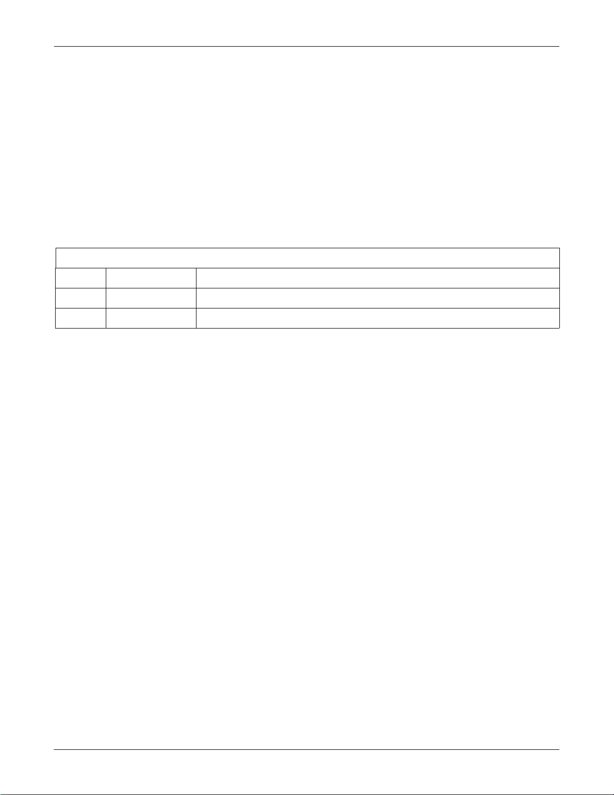
Revision History
Each page of the document has the document part number followed by a
revision letter at the bottom of the page. This letter identifies the
document’s update level. The latest letter of the alphabet corresponds to
the most current revision of the document.
The revision history of this document is summarized in the table below.
Table 1. Revision History 2019818-008
Revision Date Comment
A 15 May 2005 Initial release of manual.
B 15 July 2005 Manual updated for clarity.
Manual Purpose
Definitions
This manual supplies technical information for service representative
and technical personnel so they can maintain the equipment. Use it as a
guide for maintenance and electrical repairs considered field repairable.
Where necessary the manual identifies additional sources of relevant
information and or technical assistance.
See the operator manual for the instructions necessary to operate the
equipment safely in accordance with its function and intended use.
Items shown in Black text are keys on the keyboard, text to be
entered, or hardware items such as buttons or switches on the
equipment.
Items shown in Italicized text are software terms which identify
menu items, buttons, or options in various windows.
To perform an operation which appears with a plus (+)sign between
the names of two keys, you press and hold the first key while
pressing the second key once. This is called a keystroke combination.
For example, “Press Ctrl + Esc” means to press and hold down the
Ctrl key while pressing the Esc key.
When instructions are given for typing a precise text string with one
or more spaces, the point where the spacebar must be pressed is
indicated as:
you press the spacebar when required.
Revision B SEER Light Ambulatory Recorder/Controller 1-3
<Space>. The purpose of the < > brackets is to ensure
2019818-008
Page 10

Introduction: Manual Information
Enter means to press the “Enter” or “Return” key on the keyboard.
Do not type “enter”.
1-4 SEER Light Ambulatory Recorder/Controller Revision B
2019818-008
Page 11

Introduction: Related Manuals
Related Manuals
See the documents listed below for additional information.
Table 2. SEER Light Documents
Part Number Name
2019818-007 SEER Light Ambulatory Recorder/Controller Operator’s Manual
Revision B SEER Light Ambulatory Recorder/Controller 1-5
2019818-008
Page 12

Safety Information
Intended Use
The SEER Light recorder is a two and three channel digital Holter ECG
recorder that records the electrical signals associated with cardiac
activity fo r 24 or 48 h our s . It i s u se d in diagnosing card i ac a bno r mal i t ie s
and revealing trends or changes in heart function. This device is for the
use of trained personnel only.
This device is not intended for use on infants weighing less than 10 kg
(22 lbs).
Definitions
The terms danger, warning, and caution are used throughout this
manual to point out hazards and to designate a degree or level of
seriousness. Familiarize yourself with their definitions and significance.
Introduction: Safety Information
Warnings
Hazard is defined as a source of potential injury to a person.
DANGER indicates an imminent hazard which, if not avoided, will
result in death or serious injury.
WARNING indicates a potential hazard or unsafe practice which, if not
avoided, could result in death or serious injury.
CAUTION indicates a potential hazard or unsafe practice which, if not
avoided, could result in minor personal injury or product/property
damage.
NOTE provides application tips or other useful information.
WARNINGS
ACCIDENTAL SPILLS — If liquids have entered a
device, take it out of service and have it checked by a
service technician before it is used again. To avoid
electric shock or device malfunction liquids must not be
allowed to enter the device.
CABLES — To avoid possible strangulation, route all
cables away from patient's throat.
CARDIAC APPLICATION — This device cannot be used
for direct cardiac application.
CONDUCTIVITY — Keep the conductive parts of lead
electrodes and associated parts away from other
conductive parts, including earth.
DEFIBRILLATOR PRECAUTIONS — Do not come into
1-6 SEER Light Ambulatory Recorder/Controller Revision B
2019818-008
Page 13

Introduction: Safety Information
contact with patients during defibrillation. Otherwise,
serious injury or death could result. Patient signal inputs
labeled with the CF and BF symbols wi th paddles are
protected against damage resulting from defibrillation
voltages. To ensure proper defibrillator protection, use
only the recommended cables and leadwires. Proper
placement of defibrillator paddles in relation to the
electrodes is required to ensure successful defibrillation.
ELECTROSURGERY — If an electrosurgery device is
used, it is necessary to disconnect the patient cable from
the SEER Light recorder. Take precautions to reduce
risks of burns and injury to the patient.
LEAKAGE CURRENT — Electrical shock to patient
could result from component failure and lack of power
isolation.
In the event this syste m is used in the patient vicinity, it
must be configured in such a way that it and all of its
electrically-connecte d peripheral devices ar e isolated from
mains power to prevent excessive leakage current to the
patient. This can be accomplished through the use of
isolated mains power, or a medical grade isolation
transformer (in compliance with UL 60601, CAN/CSA
C22.2 No. 601.1, IEC 60601-1) with this system. All nonmedical peripheral devices shall comply with IEC and ISO
safety standards that are relevant to that equipment (i.e.,
IEC 60950, UL 60950).
Cautions
Use of the SEER Light Connect device in the patient
vicinity requires that these measures are observed.
PACEMAKER PATIENTS — Take precautions to avoid
risks of hazard due to the operation of a cardiac
pacemaker or other electrical stimulators.
SUPERVISED USE — This device is intended for use
under the direct supervision of a licensed health care
practitioner.
CAUTIONS
RESTRICTED SALE — U.S. federal law restricts this
device to sale by or on the order of a physician.
BEFORE OPERATION — Check that the instrument
operates properly.
DISPOSAL — At the end of its service life, the product
described in this manual, as well as its accessories, must
be disposed of in compliance with local, state, or federal
Revision B SEER Light Ambulatory Recorder/Controller 1-7
2019818-008
Page 14

Introduction: Safety Information
A
guidelines regulating the disposal of such products. If you
have questions concerning dispos al of the product , please
contact GE or its representatives.
MODIFICATIONS — Do not make an y modifications to
the device.
AFTER DEVICE USE — Clean the device after each use
to ensure trouble-free op eration for the next use.
Use a piece of damp cloth with alcohol to clean the
device and the patient cable.
The device cannot be sterilized.
Do not use xylene and petrol related liquid for
cleaning the device.
To ensure proper operation of the device, it is
necessary to periodically have the device checked by
authorized service personnel.
Check the patient cable and connectors every month
by connecting them to an ECG simulator.
Serial Number
INSTALLATION — Adhere to the following
recommendations during installation:
Install and keep device away from splashing water.
Do not install the device where it may be affected by
humidity, ventilation, direct sunlight, air
conditioning, dust, salt, sulfur, etc.
Prevent the device from ti lting, and protect it from
the possibility of vibration or shock.
Do not install the device in a chemical storage area or
where gas is generated.
Every GE Medical Systems Information Technologies device has a
unique serial number for identification. The serial number appears on
the device label similar to the one shown below
.
50
1-8 SEER Light Ambulatory Recorder/Controller Revision B
2019818-008
Page 15

Disposal of the Device
Introduction: Safety Information
When disposing the device, follow the applicable national rules and
regulations of disposal of medical equipment.
When disposing the recyclable battery, follow the applicable national
rules and regulations concerning the environmental issues.
Revision B SEER Light Ambulatory Recorder/Controller 1-9
2019818-008
Page 16

Introduction: Responsibility of the Manufacturer
Responsibility of the Manu facturer
GE is responsible for the effects of safety, reliability, and performance
only if:
Assembly operations, extensions, readju stments, modifications, or
repairs are carrie d out by persons aut horized b y GE Medica l Systems
Information Technologies.
The equipment is used in accordance with the instructions for use.
General
Refer equipment servicing to GE authorized service personnel only. Any
unauthorized attempt to repair equipment under warranty voids that
warranty.
It is the user’s respons ibility t o report the need for se rvice to GE or to one
of its authoriz ed agents.
This device is intended for use under the direct supervision of a licensed
health care practitioner.
To ensure patient safety, use only parts and access ories manufactured or
recommended by GE.
Contact GE for information before connecting any devices to this
equipment that are not recommended in this manual.
Parts and accessories used must meet t he requireme nts of t he appli cable
IEC 60601 series sa fety st andard s, and/ or t he sy stem co nfigura tion mus t
meet the requirements of the IEC 60601-1-1 medical electrical systems
standard.
The use of ACCESSORY equipment not complying with the equivalent
safety requirements of this equipment may lead to a reduced level of
safety of the resulting system. Consideration relating to the choice shall
include:
use of the accessory in the PATIENT VICINITY; and
evidence that the safety certification of the ACCESSORY has been
performed in accordance with the appropriate IEC 60601-1 and/or
IEC 60601-1-1 harmonized national standard.
1-10 SEER Light Ambulatory Recorder/Controller Revision B
2019818-008
Page 17

Introduction: Responsibility of the Manufacturer
Information Technology Equipment
The hardware components supplied by GE for the MARS® Holter
analysis workstation, on which the SEER Light Connect application
runs, are considered to be Information Technology Equipment (ITE).
These individual components have been found to comply with the
standard for Safety of Information Technology Equipment, including
Electrical Business Equipment EN60950 (UL 60950).
The software used in the MARS® Holter analysis workstation is
considered as medical software. The software has been designed and
manufactured to the appropriate medical regulations and controls.
In order for the MARS® Holter analysis workstation to comply with
medical equipment standard leakage current requirements, a medical
grade uninterruptible power supply (UPS) must be used (UL 60601-1,
CSA 22.2 No. 60601-1, EN 60601-1) to power all non-medical equipment.
In addition, non-medical electrical equipment must comply with IEC and
ISO safety standards that are relevant to that equipment (i.e., IEC
60950, Safety of Information Technology Equipment.)
Revision B SEER Light Ambulatory Recorder/Controller 1-11
2019818-008
Page 18

Equipment Symbols
The following symbols may appear on the equipment.
Attention. Consult accompanying documents.
Event.
This symbol indicates the polarity orientation that each battery should have when you insert it
into the unit. This unit requires you to insert the batteries so that the polarities are oriented in
alternating directions.
Power.
Introduction: Equipment Symbols
Stop.
Input connector.
Output connector.
This symbol indicates that the waste of electrical and electronic equipment must not be
disposed as unsorted municipal waste and must be collected separately. Please contact an
authorized representative of the manufacturer for information concerning the
decommissioning of your equipment.
1-12 SEER Light Ambulatory Recorder/Controller Revision B
2019818-008
Page 19

2 SEER Light/SEER Light
Extend Recorder
Revision B SEER Light Ambulatory Recorder/Controller 2-1
2019818-008
Page 20

For your notes
2-2 SEER Light Ambulatory Recorder/Controller Revision B
2019818-008
Page 21
SEER Light/SEER Light Extend Recorder: Component Names and Locations
Component Names and Locations
Structure
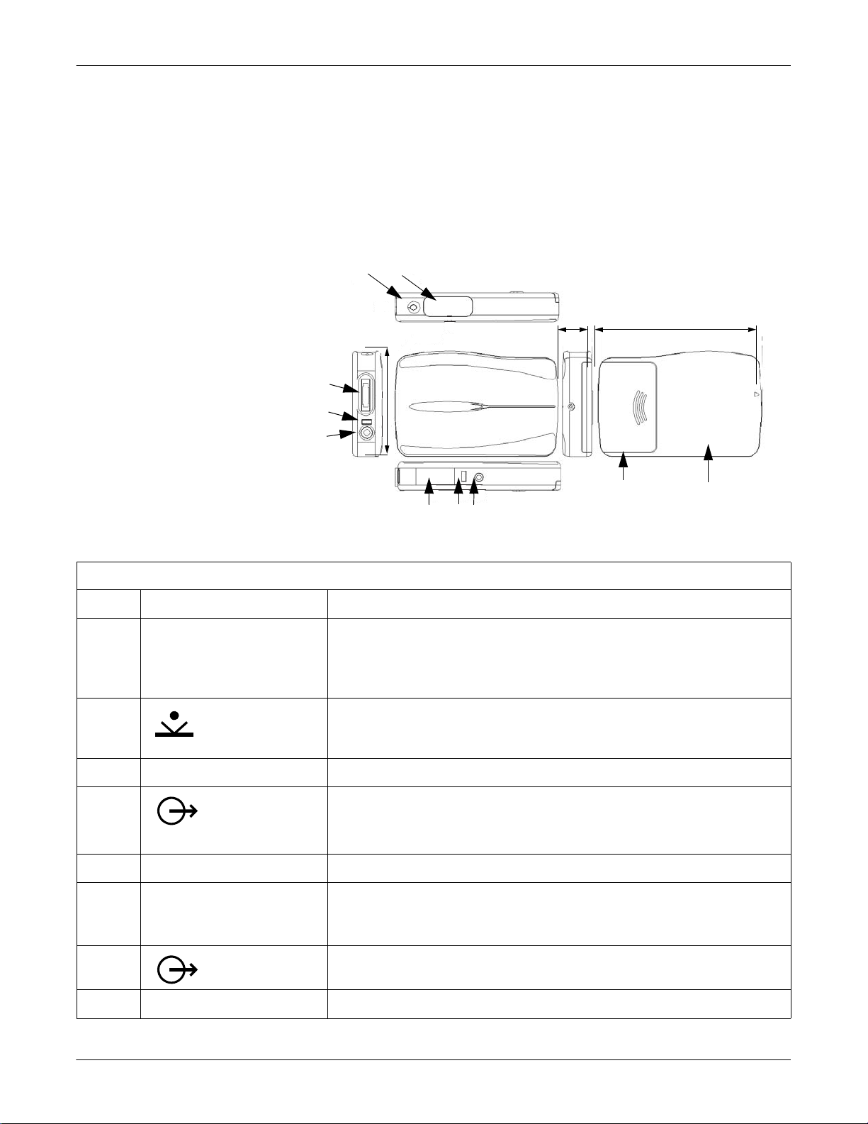
The SEER Light ambulatory recorder is shown and described below.
A B
.60 in.
(15 mm)
I
H
G
2.17 in.(55 mm)
F E D
Table 3. SEER Light Ambulatory Recorder
Item Name Description
A REC LED To display operation conditions:
After pressing the start/event button, the LED will flash twice per second for three
minutes. During this time data is not recorded.
During reco rding, the LED will flash every second.
C
3.35 in.
(85 mm)
J
017A
B
start/event button
Use to start recording.
Use to mark events during recording.
C battery compartment cover Slide the cover to open and set the batteries in the battery compartment.
D
A data output
For transfer of data to the SEER Light controller or to the SEER Light Connect device.
connector
E access LED Will flash during communication with the SEER Light controller.
F infrared terminal (I.R. Window) Used to receive the signal from the SEER Light controller to begin ECG recording.
Used to receive patient information and ECG recording starting time.
Used to confirm the ECG waveform recorded by the recorder (ECG preview).
G
B output connector
Not used.
H DATA LED The LED flashes while transferring data to the SEER Light controller.
Revision B SEER Light Ambulatory Recorder/Controller 2-3
2019818-008
Page 22

SEER Light/SEER Light Extend Recorder: Component Names and Locations
Table 3. SEER Light Ambulatory Recorder (Continued)
I patient cable connector Used to connect patient cable for ECG input.
J Stop button Push to stop recording
2-4 SEER Light Ambulatory Recorder/Controller Revision B
2019818-008
Page 23

SEER Light/SEER Light Extend Recorder: Troubleshooting
Troubleshooting
Self-Test Mode
A self-test can be done on the following functions.
1. Self-test I (pacemaker detection check mode)
Provide a pacemaker signal to the recorder with an ECG simulator.
To enter the pacemaker detection mode, set the batteries while
pressing the STOP button.
Confirm the audible sound synchronizes with the pacemaker
signal input through the patient input connector.
Remove the batteries to end the self-test.
2. Self-tes t II (accelerometer sensor check mode)
After setting the batteries, press the STOP button three times
within a second.
Confirm the audible so und synchronizes as the recorder is moved
around.
Remove the batteries to end the self-test.
Revision B SEER Light Ambulatory Recorder/Controller 2-5
2019818-008
Page 24
SEER Light/SEER Light Extend Recorder: Troubleshooting
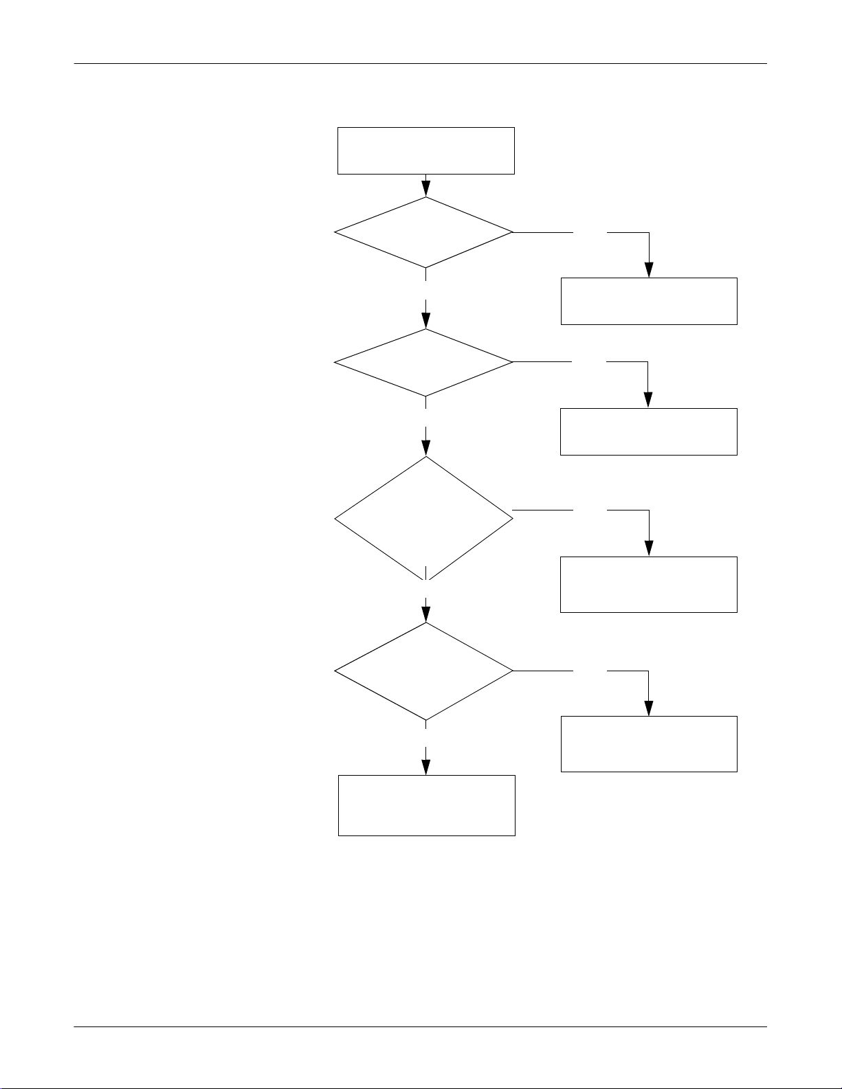
No Buzzer Sound After Installing the Batteries
No buzzer sound after
installing the batteries.
Are the batteries
installed properly?
Yes
Are the batteries
new?
Yes
Were the batteries
reinstalled over 10
seconds after the
batteries were
removed?
Yes
No
Install the batteries
properly.
No
Replace with new
batteries.
No
Reinstall the batteries
over 10 seconds after
removing them.
Are the battery
electrodes clean and
properly soldered?
Yes
Call GE service.
2-6 SEER Light Ambulatory Recorder/Controller Revision B
2019818-008
No
Call GE service.
Page 25

SEER Light/SEER Light Extend Recorder: Troubleshooting
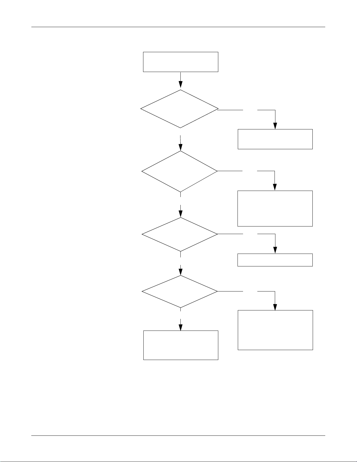
Beep Sound Will Not Stop After Installing the Batt eries
Beep sound will not stop
after installing the batteries.
Are the batteries new?
Yes
Are the alkaline
batteries
installed?
Yes
Call GE service.
No
Replace with new
alkaline batteries.
No
Set new alkaline
batteries.
Revision B SEER Light Ambulatory Recorder/Controller 2-7
2019818-008
Page 26
SEER Light/SEER Light Extend Recorder: Troubleshooting
ECG Cannot Be Previewed with Controller (I.R.)
ECG cannot be previewe d
with the controller (I.R.).
Is the dista nce from
the controller withi n
4.9 ft. (1.5 m)?
No
Yes
Is the I.R.
window facing the
controller properly?
Yes
Were the batteries
set within one hour?
Yes
Has recording
already started?
Position the controller
within 4.9 ft (1.5 m).
No
Reposition the I.R . window
properly to the controller,
or remove any obstacle
between the recorder and
the controller.
No
Reset the batteries.
Yes
No
Call GE service.
2-8 SEER Light Ambulatory Recorder/Controller Revision B
2019818-008
Preview ECG with the cable.
Cannot preview ECG by I.R.
operation if more than 3
minutes has elapsed since
recording started.
Page 27

SEER Light/SEER Light Extend Recorder: Troubleshooting
ECG Cannot be Previewed with Controller (Cable)
ECG cannot be previe wed
with the controller
(by the preview cable).
Is cable connection
proper?
Yes
Is the cable
damaged?
No
Call GE service.
No
Connect the
cable properly.
Yes
Replace with a
new cable.
Revision B SEER Light Ambulatory Recorder/Controller 2-9
2019818-008
Page 28

SEER Light/SEER Light Extend Recorder: Troubleshooting
ECG Cannot Be Previewed with SEER Light Connect Device
ECG cannot be previewe d
with the SEER Light
Connect Device.
Is the USB cable
from the Connect
plugged in?
No
Yes
Is the orange LED
on the Connect on?
Yes
Is the dista nce from
the controller withi n
4.9 ft. (1.5 m)?
Yes
Is the I.R.
window facing the
controller properly?
Yes
Plug it in.
No
Call GE Service.
No
Position the controller
within 4.9 ft (1.5 m).
No
Reposition the I.R . window
properly, or remove any
obstacle between the
recorder and the controller.
Were the batteries
installed within one
hour?
Yes
Has recording
already started?
No
Call GE service.
2-10 SEER Light Ambulatory Recorder/Controller Revision B
2019818-008
No
Reinstall the batterie s.
Yes
Cannot preview ECG by I.R.
operation if more than 3
minutes has elapsed since
recording started.
Page 29

SEER Light/SEER Light Extend Recorder: Troubleshooting
Recording Cannot Start with the Controller (I.R.)
Recording cannot start
with the controller (I.R.).
Does the controller
display “untransmitte d
data?”
No
Does
the controller display
“Already started?”
No
Is the distance
from the controller
within 4.9 ft
(1.5 m?)
Yes
Yes
Transfer previous data or
press the START button
when the controller displays
“Data still remains.”
Yes
Reset the batteries over 30
seconds after removing them.
No
Adjust the position
within 4.9 ft. (1.5 m)
from the controller.
Does the I.R. wind ow
face the controller
properly?
Yes
Call GE Service.
Revision B SEER Light Ambulatory Recorder/Controller 2-11
2019818-008
No
Reposition the I.R . windows
to face each other prop erly.
Remove any obstacles
between the recorder and
the controller.
Page 30

SEER Light/SEER Light Extend Recorder: Troubleshooting
Recording Cannot Start with the SEER Light Connect Device
Recording cannot start
with the Connect.
Is the USB cable
from the Connect
plugged in?
No
Yes
Is the orange LED
on the Connect on?
Yes
Does the controller
display “untransmitte d
data?”
No
Does
the controller display
“Already started?”
No
Plug it in.
No
Call GE Service.
Yes
Transfer previous data or
press the START button.
Yes
Reinstall the batteries over 30
seconds after removing them.
Is the distance
from the Connect
within 4.9 ft
(1.5 m?)
Yes
Does the I.R. window
face the Connect
properly?
Yes
Call GE Service.
2-12 SEER Light Ambulatory Recorder/Controller Revision B
2019818-008
No
Adjust the position
within 4.9 ft. (1.5 m)
from the Connect.
No
Reposition the I.R. windows
to face each other properl y.
Remove any obstacles
between the recorder and
the Connect.
Page 31

SEER Light/SEER Light Extend Recorder: Troubleshooting
Cannot Start by Pressing the Start Button
Cannot start by p r es sin g
the START button.
Was
the START button
pressed over 1.5
seconds?
No
Yes
Is it within
one hour of setting the
batteries?
Yes
Call GE Service
Press the START button
longer than 1.5 seconds.
No
Reset the batteries.
Revision B SEER Light Ambulatory Recorder/Controller 2-13
2019818-008
Page 32

SEER Light/SEER Light Extend Recorder: Troubleshooting
Cannot Record for 24 Hours
Cannot record for
24 hours.
Are there many
artifacts in the ECG
recording?
No
Were the batteries
removed before record ing
for 24 hours?
No
Were alkaline
batteries used?
Yes
Yes
Refer to flow chart on
artifact later in this chapter.
Yes
Don’t remove the batteries
before recording for 24 hours.
No
Use alkaline
batteries.
Are the
battery electrodes dirty
or improperly
soldered?
No
Call GE Service.
2-14 SEER Light Ambulatory Recorder/Controller Revision B
2019818-008
Yes
Clean the battery electrod es
or improve soldering.
Page 33

SEER Light/SEER Light Extend Recorder: Troubleshooting
Cannot Record for 48 Hours
Cannot record for
48 hours.
Is the recorder
labeled “SEER Light
Extend?”
Yes
Are there many
artifacts in the ECG
recording?
No
Were the batteries
removed before record ing
for 48 hours?
No
No
The recorder does not ha ve
48-hour recording
capability.
Yes
Refer to flow chart on
artifact later in this chapter.
Yes
Don’t remove the batteries
before recording for 48 hours.
Were alkaline
batteries used?
Yes
Are the
battery electrodes dirty
or improperly
soldered?
No
Call GE Service.
Revision B SEER Light Ambulatory Recorder/Controller 2-15
2019818-008
No
Use alkaline
batteries.
Yes
Clean the battery electrod es
or improve soldering.
Page 34

SEER Light/SEER Light Extend Recorder: Troubleshooting
Cannot Transfer Data from the Controller
Cannot transfer data
from the controller.
Is the transfer
cable properly connected?
Yes
Does the
controller display “No data
in the recorder?”
No
Does the
controller display
“Recorder contains data
error?”
No
Is the data output
connector clean?
No
Connect the
cable properly.
Yes
No data in the recorder.
Record ECG again.
Yes
Call GE Service.
No
Yes
Is the transfer
cable damaged?
No
Call GE Service.
2-16 SEER Light Ambulatory Recorder/Controller Revision B
2019818-008
Clean the data output
connector.
Yes
Call GE Service.
Page 35

SEER Light/SEER Light Extend Recorder: Troubleshooting
Cannot Transfer Data from the Recorder to the SEER Light Connect Device
Cannot transfer data to
the Connect.
Is the USB cable
No
Plug it in.
Is the orange LED
on the Connect on?
from the Connect
plugged in?
Yes
No
Yes
Attach the Connect to the
recorder.
Is the green LED on
the Connect on?
Yes
Is the transfer
cable properly
connected?
Yes
Does the
controller display “No data
in the recorder?”
No
Is the data output
connector clean?
Yes
No
Call GE Service.
No
Connect the
cable properly.
Yes
No data in the recorder.
Record ECG again.
No
Clean the data output
connector.
Is the transfer
cable damaged?
No
Call GE Service.
Revision B SEER Light Ambulatory Recorder/Controller 2-17
2019818-008
Yes
Call GE Service.
Page 36

SEER Light/SEER Light Extend Recorder: Troubleshooting
Record Start Date/Time is Initialized
Record start date/time
is initialized.
Was the recording
started by pressing the
START button?
Yes
Were the batteries
removed during or af ter
recording?
No
Did more than
one week pass from the
last recording?
No
Call GE Service.
No
Call GE Service.
Yes
Record start date/time will be
initialized if the batteries are
removed before transferring the
ECG data after th e START button
is pressed to start recording.
Yes
Replace the batteries.
2-18 SEER Light Ambulatory Recorder/Controller Revision B
2019818-008
Page 37

SEER Light/SEER Light Extend Recorder: Troubleshooting
Artifact on ECG Recording
Artifact on ECG
recording.
Are electrodes
connected properly on
the patient?
Yes
Is the patie nt cable
connected properly?
Yes
Is the patient
cable connector
clean?
Yes
No
Attach electrodes properly.
No
Connect the patient cable
properly.
No
Clean the patient
cable connector.
Is the patient cable
damaged?
No
Call GE Service.
Revision B SEER Light Ambulatory Recorder/Controller 2-19
2019818-008
Yes
Call GE Service.
Page 38

SEER Light/SEER Light Extend Recorder: Troubleshooting
Cannot Detect Pacemaker Pulse
Cannot detect
pacemaker pulse.
Insert the batteries while
pressing the STOP button.
Disconnec t the patient ca ble
and touch the electrode
connector with a finger.
Does audible beep
sound?
No
Call GE Medical Systems
Information Technologies
Service.
Yes
Normal pacemaker detection circuit.
Confirm pacemaker pulse detection
by the Preview function of the
controller. Reposition the CH1 if the
pulse signals are too small.
2-20 SEER Light Ambulatory Recorder/Controller Revision B
2019818-008
Page 39

3 SEER Light/SEER Light
Extend Controller
Revision B SEER Light Ambulatory Recorder/Controller 3-1
2019818-008
Page 40

For your notes
3-2 SEER Light Ambulatory Recorder/Controller Revision B
2019818-008
Page 41

SEER Light/SEER Light Extend Controller: Component Names and Locations
Component Names and Locations
Structure
Below are the names of each part on the SEER Light/SEER Light Extend
Controller.
A
1.2 in.
3.5 in. (90 mm)
7.9 in. (200 mm)
(30 mm)
D
E
F
G
H
I
J
K
B
C
037A
L
Table 4. Controller Parts List
Item Name Description
A
input connector
Used to connect to the SEER Light recorder to check recording conditions.
NOTE This feature is reserved for future use.
B infrared terminal Used to communicate with the SEER Light recorder.
Transfer the instructions to a SEER Light recorder before recording.
Receive ECG waveform recording data from a SEER Light recorder to preview.
Revision B SEER Light Ambulatory Recorder/Controller 3-3
2019818-008
Page 42

SEER Light/SEER Light Extend Controller: Component Names and Locations
Table 4. Controller Parts List (Continued)
Item Name Description
C data transfer cable Used to transfer data from the SEER Light recorder. When not in use, store the cable in
the guide on the backside panel.
D
Used to turn the power on and off.
power button
E Holter card slot Used to insert a Holter card.
F LCD (liquid crystal display) Displays operating conditions.
G F1 button Used to enter the preview mode (wired or wireless) to confirm the quality of ECG
recording.
H F2 button Used to enter the data transfer mode to transmit data to a Holter card.
I F3 button Used to start recording of the SEER Light recorder and to start transferring data to a
Holter card.
J
set-up button (
K patient information entry
)
Used to select settings.
Enter the patient’s alphanumeric information.
buttons
L battery cover In direction indicated, slide the cover open and place four new alkaline AAA type batteries
in the battery box.
3-4 SEER Light Ambulatory Recorder/Controller Revision B
2019818-008
Page 43

SEER Light/SEER Light Extend Controller: Troubleshooting
Troubleshooting
Software Version
Self-Test
The software version of the SEER Light/SEER Light Extend Controller
appears in the lower right hand corner of the display upon start up.
A self-test can be done on the following functions.
1. Button check mode:
Enter the Set-up Condition display mode by pressing the POWER
button and button simultaneously. Continue to hold the button
while releasing the POWER button.
Press the CLEAR button at the Set-up Condition display mode.
Press the number 0 at the Factory Settings display mode.
The name of the button that was pressed will be displayed, and
an audible sound will be heard when the respective button is
pressed once.
NOTE
If the ENTER button is pressed three times the unit will
enter into the LCD check mode.
Turn off the power to end this function test.
2. LCD check mode:
Enter the Set-up Condition display mode by pressing the POWER
button and button simultaneously. Continue to hold the button
while releasing the POWER button.
Press the CLEAR button at the Set-up Condition display mode.
Press the number 0 at the Factory Settings display mode.
In the button check mode display press the ENTER button three
times, and the LCD display will appear darkened.
Press the POWER button to end this function test.
Revision B SEER Light Ambulatory Recorder/Controller 3-5
2019818-008
Page 44

SEER Light/SEER Light Extend Controller: Troubleshooting
No Operation After Inserting Batteries and Pressing Power Button
No operation after insertin g
batteries and pressing the
POWER button.
Are the batteries
set properly?
Yes
Do the
batteries have su f ficient
power of >4.5 V?
Yes
Did the
beep sound when the
POWER button was
pressed?
No
No
Set the batteries
properly.
No
Replace with new
batteries.
Yes
Call GE service.
Call GE service.
3-6 SEER Light Ambulatory Recorder/Controller Revision B
2019818-008
Page 45

SEER Light/SEER Light Extend Controller: Troubleshooting
ECG Cannot be Previewed with the Controller (I.R.)
ECG cannot be previewe d
with the controller (I.R.)
Communication Error
Is the dista nce from
the recorder within
4.9 ft. (1.5 m)?
No
Yes
Is the I.R.
window facing the
recorder properly?
Yes
Has recording
already started?
No
Call GE service.
Position the recorder
within 4.9 ft. (1.5 m).
No
Reposition the I.R . window
properly to the recorder,
or remove any obstacle
between the recorder and
the controller.
Yes
Preview ECG with the cable.
Cannot preview ECG by I.R.
operation over 3 minutes after
recording started.
Revision B SEER Light Ambulatory Recorder/Controller 3-7
2019818-008
Page 46

SEER Light/SEER Light Extend Controller: Troubleshooting
ECG Cannot be Previewed by the Controller (Cable)
ECG cannot be previe wed
by the controller
(by the preview cable).
Is cable connection
proper?
Yes
Is the cable
damaged?
No
Call GE service.
No
Connect the
cable properly.
Yes
Call GE service.
3-8 SEER Light Ambulatory Recorder/Controller Revision B
2019818-008
Page 47

SEER Light/SEER Light Extend Controller: Troubleshooting
Cannot Start Recording (I.R.)
Cannot start recording
(I.R.).
Does
the controller display
“Already started?”
Yes
No
Is the distance from
the recorder within
4.9 ft. (1.5 m)?
Yes
Does the I.R. window
face the controller
properly?
Yes
Has
over 60 minutes
passed since recording
started?
Reset the batteries over 30
seconds after removing them.
No
Adjust the position within
4.9 ft. (1.5 m) from the
recorder.
No
Reposition the I.R. windo ws
to face each other properly.
Remove any obstac les
between the recorder and
the controller.
Yes
No
Call GE service.
Revision B SEER Light Ambulatory Recorder/Controller 3-9
2019818-008
If over 60 minutes have
passed, the SEER Light
cannot start by I.R.
operation.
Page 48

SEER Light/SEER Light Extend Controller: Troubleshooting
Pressing the Appropriate Key(s) Does Not Start Operation
Pressing the appropriate
key(s) does not start op erat ion .
Can
the operation panel
key(s) be pressed
properly?
No
Yes
Is there
debris between PC
board and key sheet
panel?
No
Call GE service.
Call GE service.
Yes
Call GE service.
3-10 SEER Light Ambulatory Recorder/Controller Revision B
2019818-008
Page 49

SEER Light/SEER Light Extend Controller: Troubleshooting
Beep Sounds While the Flash Card is Inserted
Beep sounds while the
flash card is inserted.
The display is distorted.
Is the flash card
inserted completely?
Yes
Is the
card inserted in the
opposite direction?
No
Call GE service.
No
Insert the card
completely.
Yes
Insert the card
properly.
Revision B SEER Light Ambulatory Recorder/Controller 3-11
2019818-008
Page 50

SEER Light/SEER Light Extend Controller: Troubleshooting
Data Cannot be Transferred from the Recorder
Data cannot be transferred
from the recorder .
Is the data output
connector clean?
Yes
Is the connector
damaged?
No
Has
the compact flash card
been formatted?
Yes
Is the card defective?
No
No
Clean the
connector.
Yes
Replace th e
connector.
No
Format the compact
flash card.
Yes
Replace with a
new card.
Does data remain on
the card?
No
Are
there distorted card
connector pins?
No
Call GE service.
Yes
Transfer the
data to the PC.
Yes
Call GE service.
3-12 SEER Light Ambulatory Recorder/Controller Revision B
2019818-008
Page 51

SEER Light/SEER Light Extend Controller: Troubleshooting
Recording Start Date/Time is Not Correct
Recording start date/ time
is not correct.
Time is Not Correct
Is date within
one month?
Yes
See next flowchart.
Time is not correct.
Is it within 5 years
of use?
Yes
No
Adjust date.
No
Call GE service.
Are the
battery electrodes
clean or properly
solder?
Yes
Replace the PC boards.
Revision B SEER Light Ambulatory Recorder/Controller 3-13
2019818-008
No
Clean the electrodes
or improve soldering.
Page 52

SEER Light/SEER Light Extend Controller: Inspection
Inspection
Production process inspection sheet and inspection procedure.
M. No.
Product Model Name SEER Light Controller Date (Start Inspection) Approval Audit
Serial No. Board No.
Production Lot No.
Program Version Production Specification
High temperature heat run (40 to 48 hours) Start and End Date
Inspection Before Heat-Run Staff
No. Item Inspection Procedures Result Accept Reject
1 Appearance Check paint condition, no scratches or stains on LCD and cases, clear wording,
etc. Check connector pin of memory card for breaks, bends, etc.
2 Power switch Turn ON the power switch. Ensure there are buzzer sounds and the factory reset
menu appears on the LCD. Confirm program version number.
3 Set the time Set year, month, date, and time. Turn off the Auto Power function for heat-run
inspection.
4 Key/LCD check Under the inspection mode, ensure the key input and LCD display are normal,
LCD backlight is lit, and the keys should not stick when pressed.
5 Leakage current Patient leakage current is less than 10 µA. µA
6 Power ON Insert the batteries and confirm buzzer one time. Press start switch, confirm to buzzer and
blink red LED. Then press stop switch and check buzzer sound and LED blinking are
stopped.
7 Start test Ensure that the SEER Light is starting (straight line: 1.5 m).
8 IrDA preview
check
9 Preview check
with cable
10 Analog output Using inspection contr ol ler with c able , conf i rm ana log wavef orm s 1 ch, 2 ch, and 3 ch are
11 Transfer test Connect the SEER Light. Ensure that data is transferred and that the data can be
12 Check settings Check the year, month, date, and time (with ±1 minute).
13 Reset menu Used to initialize the settings (menu).
14 Auto Power Off
function
15 Appearance Check painting conditions such as no scratches stains on LCD cases, clear wording,
16 Supply current Start at 6 V. The supply current is 60 ±6 mA. mA
No. Visual Inspection Accept Reject No. Visual Inspection Accept Reject
1 Battery mark 1 place 4 Electrode welding 2 places
2 Ribbon 1 place 5 LCD boards, connector cutting 1 place
3 Board installation 1 place 6 Main body assembly 4 places
Notes:
Use SEER Light, which is pre-installed with ECG wave, and ensure that the
displayed waveform of 1 ch, 2 ch, and 3 ch are normal under the preview function.
Use SEER Light, which is pre-installed with ECG wave, and ensure that the
displayed analog waveform of 1 ch, 2 ch, and 3 ch are normal.
normal.
installed onto the Holter card.
Turn ON the power switch. Check that the power is automatically switched off if no
operation for 15 minutes continuously.
etc. Check ser ia l pl at e and ba tt e r y ma r k se al (v er s io n nu m be r ) is se cu re ly af fixed.
Ver. No.
3-14 SEER Light Ambulatory Recorder/Controller Revision B
2019818-008
Page 53

4 SEER Light Connect
Revision A SEER Light Ambulatory Recorder/Controller 4-1
2019818-008
Page 54

For your notes
4-2 SEER Light Ambulatory Recorder/Controller Revision A
2019818-008
Page 55

SEER Light Connect: Component Names and Locations
Component Names and Locations
The SEER Light Connect is shown and described below. It is used as a
direct interface connection between the recorder and the Holter analysis
system. This device is also referred to as “the connect” in this document.
Structure
Below are the names of each part on the SEER Light Connect.
D
A
C
B
Name Function
A data transfer cable Used to transfer data from the SEER Light recorder
to the SEER Light Connect.
B infrared terminal Used to communicate with the SEER Light
recorder.
Receives ECG waveform data from a SEER
Light recorder to preview.
Transfers patient demographics to the SEER
Light recorder.
Starts the SEER Light recorder.
C USB Connection Uses a USB patch cord to transfer data from the
SEER Light Connect to the Holter analysis system.
084A
D LED indicator Flashes when data is transferring.
Lights without flashing when a proper connection
exists.
Revision A SEER Light Ambulatory Recorder/Controller 4-3
2019818-008
Page 56

Troubleshooting
SEER Light Connect: Troubleshooting
WARNING
LEAKAGE CURRENT—Electrical shock to patient could
result from component failure and lack of power
isolation.
In the event this syste m is used in the patient vicinity, it
must be configured in such a way that it and all of its
electrically-connecte d peripheral devices ar e isolated from
mains power to prevent excessive leakage current to the
patient. This can be accomplished through the use of
isolated mains power, or a medical grade isolation
transformer (in compliance with UL 60601, CAN/CSA
C22.2 No. 601.1, IEC 60601-1) with this system. All nonmedical peripheral devices shall comply with IEC and ISO
safety standards that are relevant to that equipment (i.e.,
IEC 60950, UL 60950).
Software Version
Use of the SEER Light Connect device in the patient
vicinity requires that these measures are observed.
To view the software version of the SEER Light Connect device, click
About in the SEER Light Hookup window.
4-4 SEER Light Ambulatory Recorder/Controller Revision A
2019818-008
Page 57

SEER Light Connect: Troubleshooting
ECG Cannot Be Previewed with SEER Light Connect Device
ECG cannot be previewe d
with the SEER Light
Connect Device.
Is the USB cable
from the Connect
plugged in?
No
Yes
Is the orange LED
on the Connect on?
Yes
Is the dista nce from
the controller withi n
4.9 ft. (1.5 m)?
Yes
Is the I.R.
window facing the
controller properly?
Yes
Plug it in.
No
Call GE Service.
No
Position the controller
within 4.9 ft (1.5 m).
No
Reposition the I.R . window
properly, or remove any
obstacle between the
recorder and the controller.
Were the batteries
installed within one
hour?
Yes
Has recording
already started?
No
Call GE service.
Revision A SEER Light Ambulatory Recorder/Controller 4-5
2019818-008
No
Reinstall the batterie s.
Yes
Cannot preview ECG by I.R.
operation if more than 3
minutes has elapsed since
recording started.
Page 58

SEER Light Connect: Troubleshooting
Recording Cannot Start with the SEER Light Connect Device
Recording cannot start
with the Connect.
Is the USB cable
from the Connect
plugged in?
No
Yes
Is the orange LED
on the Connect on?
Yes
Does the controller
display “untransmitte d
data?”
No
Does
the controller display
“Already started?”
No
Plug it in.
No
Call GE Service.
Yes
Transfer previous data or
press the START button.
Yes
Reinstall the batteries over 30
seconds after removing them.
Is the distance
from the Connect
within 4.9 ft
(1.5 m?)
Yes
Does the I.R. window
face the Connect
properly?
Yes
Call GE Service.
4-6 SEER Light Ambulatory Recorder/Controller Revision A
2019818-008
No
Adjust the position
within 4.9 ft. (1.5 m)
from the Connect.
No
Reposition the I.R. windows
to face each other properl y.
Remove any obstacles
between the recorder and
the Connect.
Page 59

SEER Light Connect: Troubleshooting
Cannot Transfer Data from the Recorder to the SEER Light Connect Device
Cannot transfer data to
the Connect.
Is the USB cable
No
Plug it in.
Is the orange LED
on the Connect on?
from the Connect
plugged in?
Yes
No
Yes
Attach the Connect to the
recorder.
Is the green LED on
the Connect on?
Yes
Is the transfer
cable properly
connected?
Yes
Does the
controller display “No data
in the recorder?”
No
Is the data output
connector clean?
Yes
No
Call GE Service.
No
Connect the
cable properly.
Yes
No data in the recorder.
Record ECG again.
No
Clean the data output
connector.
Is the transfer
cable damaged?
No
Call GE Service.
Revision A SEER Light Ambulatory Recorder/Controller 4-7
2019818-008
Yes
Call GE Service.
Page 60

SEER Light Connect: Troubleshooting
Recording Start Date/Time is Not Correct
Recording start date/ time
is not correct.
Is date correct on
the PC?
Yes
Call GE Service.
No
Adjust date/time on the PC.
4-8 SEER Light Ambulatory Recorder/Controller Revision A
2019818-008
Page 61

5 Maintenance
Revision B SEER Light Ambulatory Recorder/Controller 5-1
2019818-008
Page 62

For your notes
5-2 SEER Light Ambulatory Recorder/Controller Revision B
2019818-008
Page 63

Maintenance
Visual Inspection
Maintenance: Maintenance
Perform a visual inspection daily. If you notice any items that need
repair, contact an authorized GE Medical Systems Information
Technologies service person to make the repairs.
Check the case and display screen for cracks or other damage.
Regularly inspect all cords and cables for fraying or other damage.
Inspect all plugs, cables, and connectors for bent prongs or pins.
Verify that all cords and connectors are securely seated.
Inspect controls for proper operation.
Inspect the LCD to make sure all the segments function.
Precautions
Cleaning
Cleaning Frequency
Do not immerse any part of the equipment in water.
Do not use organic solvents, ammonia based solutions, or abrasive
cleaning agents which may damage equipme nt surfaces.
NOTE
Remove the batteries before cleaning
Clean the exterior surfaces with a clean, soft cloth and a mild
dishwashing detergent diluted in water.
Wring the excess water from the clot h. Avoid contact with open
vents, plugs, or connectors.
Do not spray or spill fluid directly on the reco rder/controller.
Dry the surfaces with a clean cloth or paper towel.
With each new patient use, clean the SEER Light Recorder/Controller
and the SEER Light recorder pouch, leadwires, and patient cable.
Revision B SEER Light Ambulatory Recorder/Controller 5-3
2019818-008
Page 64

Maintenance: Storing the Recorder
Storing the Recorder
When the SEER Light Recorder/C ontrol ler wi ll not be in use fo r a period
of time:
Remove the batteries
Disconnect and properly store any patient cables.
Memory card may remain in the recorder.
5-4 SEER Light Ambulatory Recorder/Controller Revision B
2019818-008
Page 65

Maintenance: Maintenance/Repair Log
Maintenance/Repair Log
Unit Serial Number:
Institution Name:
Date Maintenance/Repair Technician
Revision B SEER Light Ambulatory Recorder/Controller 5-5
2019818-008
Page 66

Maintenance: Maintenance/Repair Log
Maintenance/Repair Log
Unit Serial Number:
Institution Name:
Date Maintenance/Repair Technician
5-6 SEER Light Ambulatory Recorder/Controller Revision B
2019818-008
Page 67

Appendix A —
Technical Specifications
Revision B SEER Light Ambulatory Recorder/Controller A-1
2019818-008
Page 68

For your notes
A-2 SEER Light Ambulatory Recorder/Controller Revision B
2019818-008
Page 69

Appendix A: Technical Specifications
Technical Specifications
SEER Light/SEER Light Extend Ambulatory Recorder
The following table lists the specifications for the SEER Light/
SEERLight Extend Ambulatory Recorder.
Description Specification
Dimensions Height: 54 mm (2.1 in)
Width: 85 mm (3.35 in)
Depth: 15 mm (0.6 in)
Weight 72 g (2.5 oz) including batteries
Operating temperature 0 to 45°C (32 to 113°F)
Operating humidity 10 to 95% relative humidity (no condensation
allowed)
Storage temperature –20 to 65° C (-4 to 149°F)
Storage humidity 5 to 90% relative humidity (no condensation
allowed)
Material Aluminum ABSPC (main body)
Recording time within 24 hours — SEER Light
within 48 hours — SEER Light Extend
Recording method Digital memory
Power supply 2 x AAA Alkaline battery
Recording channel ECG: 3 channels
Movement level: 1 channel
Pacemaker pulse: 1 channel
Pacemaker detection channel CH1
Memory 32 Mbyte
Input level 16 mV p-p
A/D converter 10 bit, 8 ms sampling
Frequency response 0.05 to 40 Hz
Safety Type B
Input impedance Over 10 M Ohms
Time data backup Within 1 week (when started by the Cardy 301
recorder)
Revision B SEER Light Ambulatory Recorder/Controller A-3
2019818-008
Page 70

Appendix A: Technical Specifications
SEER Light Ambulatory Controller
The following table lists the specifications for the SEER Light
Ambulatory Controller.
Description Specification
Dimensions Height: 200 mm (7.9 in)
Weight 285 g (9.9 oz) including batteries
Operating temperature 10 to 35°C (50 to 95°F)
Operating humidity 10 to 95% relative humidity (no condensation
Storage temperature –20 to 65° C (-4 to 149°F)
Storage humidity 5 to 90% relative humidity (no condensation
Power supply 4 x AAA Alkaline battery
Width: 90 mm (3.5 in)
Depth: 25 mm (1.2 in)
allowed)
allowed)
Vibration endurance Operation: 0.5 G (10 to 20 Hz)
Non operation: 3.0 G (100 to 300 Hz)
Data transfer medium Compact flash card
Time accuracy + 60 seconds per month
A-4 SEER Light Ambulatory Recorder/Controller Revision B
2019818-008
Page 71

Appendix A: Technical Specifications
SEER Light Connect Device
The following ta ble lists the specifications for the SEER Light Connect
device.
Dimensions Height: 13 mm (.51 in)
Weight 87 g (.19 lbs)
Operating temperature 10 to 35°C (50 to 95°F)
Operating humidity 10 to 95% relative humidity (no condensation
Storage temperature –20 to 65° C (-4 to 149°F)
Storage humidity 5 to 90% relative humidity (no condensation
Description Specification
Width: 90 mm (3.54 in)
Depth: 51 mm (2.01 in)
Cable length: 260 mm (10.24 in)
allowed)
allowed)
Power supply DC 5V
Recorders SEER Light Recorder
SEER Light Extend Recorder
Revision B SEER Light Ambulatory Recorder/Controller A-5
2019818-008
Page 72

For your notes
Appendix A: Technical Specifications
A-6 SEER Light Ambulatory Recorder/Controller Revision B
2019818-008
Page 73

Appendix B —
Electromagnetic
Compatibility
Revision B SEER Light Ambulatory Recorder/Controller B-1
2019818-008
Page 74

For your notes
B-2 SEER Light Ambulatory Recorder/Controller Revision B
2019818-008
Page 75

Electromagnetic Compatibility: Electromagnetic Compatibility (EMC)
Electromagnetic Compatibility (EMC)
Changes or modification to this system not expressly approved by GE
Medical System could cause EMC issues with this or other equipment.
This system is designed and tested to comply with applicable regulation
regarding EMC and needs to be installed and put into service according
to the EMC information stated as follows.
WARNING
Use of portable phones or other radio frequency (RF)
emitting equi pment near the sys te m may cau s e
unexpected or adverse operation.
WARNING
The equipment or system should not be used adjacen t to ,
or stacked with, other equipment. If adjacent or stacked
use is necessary, the equipment or system should be
tested to verify normal operation in the configuration in
which it is being used.
Guidance and Manufacturer’s Declaration – Electromagnetic
Emissions
The SEER Light recorder and controller are intended for use in the
electromagnetic environment specified below. It is the responsibility of
the customer or user to ensure that the SEER Light recorder and
controller are used in such an environment.
Emissions Test Compliance Electromagnetic Environment - Guidance
The equipment uses RF energy only for its
RF emissions
CISPR11
RF emissions
CISPR11
Harmonic Emissions
EN 61000-3-2
Voltage fluctuations/
Flicker emissions
EN 61000-3-3
Group 1
Class A
Class A
Complies
internal function. Therefore, its RF emissions
are very low and are not likely to cause any
interference in nearby electronic equipment.
The equipment is suitable for use in all
establishments including domestic
establishments and those directly connected to
the public low-voltage power supply network
that supplies buildings used for domestic
purposes.
Revision B SEER Light Ambulatory Recorder/Controller B-3
2019818-008
Page 76

Electromagnetic Compatibility: Electromagnetic Compatibility (EMC)
Guidance and Manufacturer’s Declaration – Electromagnetic
Immunity
The SEER Light recorder and controller are intended for use in the
electromagnetic environment specified below. It is the responsibility of
the customer or user to ensure that the SEER Light recorder and
controller are used in such an environment.
Immunity Test EN 60601 Test Level Compliance Level
Electrostatic
discharge (ESD)
EN 61000-4-2
Electrical fast
transient/burst
EN 61000-4-4
Surge
EN 61000-4-5
Voltage dips, short
interruptions and
voltage variations on
power supply input
lines
EN 61000-4-11
Power frequency
(50/60 Hz) magnetic
field
EN 61000-4-8
± 6 kV contact
± 8 kV air
± 2 kV for power supply lines
±1 kV for input/output lines
± 1 kV differential mode
± 2 kV common mode
<5% Ut (>95% dip in Ut)
for 0.5 cycles
40% Ut (60% dip in Ut)
for 5 cycles
70% Ut (30% dip in Ut)
for 25 cycles
<5% Ut (>95% dip in Ut)
for 5 sec
3 A/m 3 A/m Power frequency magnetic fields should be
± 6 kV contact
± 8 kV air
± 2 kV for power supply lines
±1 kV for input/output lines
± 1 kV differential mode
± 2 kV common mode
<5% Ut (>95% dip in Ut)
for 0.5 cycles
40% Ut (60% dip in Ut)
for 5 cycles
70% Ut (30% dip in Ut)
for 25 cycles
<5% Ut (>95% dip in Ut)
for 5 sec
Electromagnetic Environment -
Guidance
Floors should be wood, concrete or
ceramic tile. If floors are covered with
synthetic material, the relative humidity
should be at least 30%.
Not applicable. The SEER Light recorder
and controller are not powered by Mains
power.
Not applicable. The SEER Light recorder
and controller are not powered by Mains
power.
Not applicable. The SEER Light recorder
and controller are not powered by Mains
power.
at levels characteristics of a typical location
in a typical commercial or hospital
environment.
NOTE
Ut is the AC mains voltage prior to application of the test level.
B-4 SEER Light Ambulatory Recorder/Controller Revision B
2019818-008
Page 77

Electromagnetic Compatibility: Electromagnetic Compatibility (EMC)
PPP
Guidance and Manufacturer’s Declaration – Electromagnetic
Immunity
The SEER Light recorder and controller are intended for use in the
electromagnetic environment specified below. It is the responsibility of
the customer or user to assure that the SEER Light recorder and
controller are used in such an environment.
Immunity Test EN 60601 Test Level Compliance Level Electromagnetic Environment – Guidance
Portable and mobile RF communications equipment should not
be used closer to any part of the equipment, including cables,
than the recommended separation distance calculated from the
equation applicable to the frequency of the transmitter.
Recommended separation distance
Conducted RF
EN 61000-4-6
Radiated RF
EN 61000-4-3
NOTE 1: At 80 MHz and 800 MHz, the higher frequency range applies.
NOTE 2: These guidelines may not apply in all situations. Electromagnetic propagation is affected by reflection from structures, objects,
and people.
a
Field strengths from fixed transmitters, such as base stations for radio (cellular/cordless) telephones and land mobile radio, AM
and FM radio broadcast, and TV broadcast cannot be predicted theoretically with accuracy. To assess the electromagnetic
environment due to fixed RF transmitters, an electromagnetic site survey should be considered. If the measured field strength
in the location in which the equipment is used exceeds the applicable RF compliance level above, the equipment should be
observed to verify normal operation. If abnormal performance is observed, additional measures may be necessary, such as
re-orienting or relocating the equipment.
b
Over the frequency range 150 KHz to 80 MHz, field strengths should be less than 3 V/m.
3 Vrms
150 KHz to 80 MHz
3 V/m
80 MHz to 2.5 GHz
3 V rms
3 V/m
d = 1.2
d = 1.2 80 MHz to 800 MHz
d = 2.3 800 MHz to 2.5 GHz
where P is the maximum output power rating of the transmitter
in watts (W) according to the transmitter manufacturer, and d is
the recommended separation distance in meters (m).
Field strengths from fixed RF transmitters, as determined by an
electromagnetic site survey
compliance level in each frequency range
Interference may occur in the vicinity of equipment marked with
the following symbol:
a
, should be less than the
b
.
Revision B SEER Light Ambulatory Recorder/Controller B-5
2019818-008
Page 78

Electromagnetic Compatibility: Electromagnetic Compatibility (EMC)
PPP
P
Recommended Separation Distances
The table below provides the recommended separation distances (in
meters) between portable and mobile RF communication equipment and
the SEER Light recorder and controller.
The SEER Light recorder and controller are intended for use in the
electromagnetic environment on which radiated RF disturbances are
controlled. The customer or the user of the SEER Light recorder and
controller are can help prevent electromagnetic interference by
maintaining a minimum distance between portable and mobile RF
communications equipment (transmitters) and the SEER Light recorder
and controller as recommended below, according to the maximum output
power of the communications equipment.
Separation Distance in Meters (m) According to Frequency of Transmitter
Rated Maximum Output
Power of Transmitter in
Watts
0.01 0.12 0.12 0.12 0.23
0.1 0.38 0.38 0.38 0.73
1 1.2 1.2 1.2 2.3
10 3.8 3.8 3.8 7.3
100 12 12 12 23
NOTE 1: At 80 MHz and 800 MHz, the separation distance for the higher frequency range applies.
150 kHz to 80 MHz
outside ISM bands
d = 1.2
For transmitters rated at a maximum ou tp ut po wer n ot lis ted ab ove , the
recommended separation distance [d] in meters (m) can estimated using
the equation applicable to the frequency of the transmitter, where P is
the maximum output power rating of the transmitter in watts (w)
according to the transmitter manufacturer.
NOTE
These guidelines may not apply in all situations. Electromagnetic
propagation is affected by absorption and reflection from structures,
objects, and people.
150 kHz to 80 MHz
in ISM bands
d = 1.2
80 MHz to 800 MHz
d = 1.2
800 MHz to 2.5 GHz
d = 2.3
B-6 SEER Light Ambulatory Recorder/Controller Revision B
2019818-008
Page 79

Electromagnetic Compatibility: Electromagnetic Compatibility (EMC)
Compliant Cables and Accessories
WARNING
The use of accessori es, tra nsducers and cable s other t han
those specified may result in increased emissions or
decreased immunity performance of the equipment or
system.
The table below lists cables, transducers, and other applicable
accessories with which GE Medical Systems claims EMC compliance.
NOTE
Any supplied accessories that do not affect EMC compliance are not
included.
Part No Description Maximum Lengths
2008750-002 SEER Light 64MB Compact Flash NA
2008751-001 Compact Flash to PC Adapter NA
2008594-00X SEER Light Patient Cable 1m
3801-005 Battery Alkaline 1.5V AAA NA
Revision B SEER Light Ambulatory Recorder/Controller B-7
2019818-008
Page 80

For your notes
Electromagnetic Compatibility: Electromagnetic Compatibility (EMC)
B-8 SEER Light Ambulatory Recorder/Controller Revision B
2019818-008
Page 81

Index
Revision B SEER Light Ambulatory Recorder/Controller Index-1
2019818-008
Page 82

Index-2 SEER Light Ambulatory Recorder/Controller Revision B
2019818-008
Page 83

A
abrasive cleaning agents 3
Access LED 3
Accessories 10
Accidental spills warning 6
Alphanumeric
keypad 4
Authorized service 10
B
Battery box
controller
cover 4
recorder
cover 3
C
Cables warning 6
Cardiac application warning 6
Caution definition 6
certification
CSA 22.2 No. 601 11
EN 60950 (UL 950) 11
IEC 601-1 11
UL 2601-1 11
Cleaning 3
cleaning
what to use 3
Conductivity warning 6
D
Danger definition 6
DATA LED 3
Data transfer
data transfer cable 4
Defibrillation warning 6
Definition
danger, warning, caution, note 6
Disposal 9
caution 7
E
Electrosurgery warning 7
Equipment Symbols 12
Equipment symbols 9
Event 12
F
Function buttons (F1, F2, F3) 4
H
Holter card slot 4
I
IEC 10
immersion in water 3
information technology equipment 11
Infrared terminal 3
Input connector 12, 3
Intended use 6
L
LCD 4
Leakage current warning 7, 4
M
Maintenance 5, 3
manual
definitions 3
purpose 3
revision history 3
manuals
related 5
Modifications caution 8
N
Note definition 6
O
Output connector 12, 3
P
Pacemaker
warning 7
Patient cable
connector 4
Polarity of batteries 12
Power 12
button on controller 4
Precautions 3
R
REC LED 3
S
Safety Information 6
Serial Number 8
Serial number 8
Set-up button 4
Start/event button 3
Stop 12
Stop button
recorder 4
Storing
recorder 4
Supervised use warning 7
Symbols on equipment 9
V
visual inspection 3
W
Warning definition 6
Revision B SEER Light Ambulatory Recorder/Controller Index-3
2019818-008
Page 84

Index
Index-4 SEER Light Ambulatory Recorder/Controller Revision B
2019818-008
Page 85

Page 86

 Loading...