

Page 1
GE
Security
Legend
User Manual
Page 2

Copyright Copyright © 2005, GE Security Inc. All rights reserved.
This document may not be copied in whole or in pa rt, or otherwise reproduced except as
specifically permitted under US copyright law, without the prior written consent from GE.
Document number/revision: 1052027A.
Disclaimer The information in this document is subject to change without notice. GE, in keeping pace with
Trademarks and patents Legend product and logo are trademarks of GE Security.
Software license agreement GE software supplied with GE products is proprietary and furnished under license and can be
Intended use Use this product only for the purpose for which it was designed; refer to the data sheet and user
technological advances, is a company of product innovation. Therefore, it is difficult to ensure
that all information provided is entirely accurate and up-to-date. GE accepts no responsibility
for inaccuracies or omissions and specifically disclaims any liabilities, losses, or risks, personal
or otherwise, incurred as a consequence, directly or indirectly, of the use or application of any
of the contents of this document.
This publication may contain examples of screen captures and reports used in daily operations.
Examples may include fictitious names of individuals and companies. Any similarity to names
and addresses of actual businesses or persons is entirely coincidental.
GE and the GE monogram are registered trademarks of General Electric.
Other trade names used in this document may be trademarks or registered trademarks of the
manufacturers or vendors of the respective products.
used or copied only in accordance with the license terms.
THE ENCLOSED PROGRAM IS FURNISHED SUBJECT TO THE TERMS AND CONDITIONS OF THIS
AGREEMENT. RETENTION OF THE PROGRAM FOR MORE THAN 30 DAYS, OPENING OF THE
SEALED WRAPPER, IF ANY, SURROUNDING THE PROGRAM, OR USE OF THE PROGRAM IN ANY
MANNER WILL BE CONSIDERED ACCEPTANCE OF THE AGREEMENT TERMS. IF THESE TERMS ARE
NOT ACCEPT ABLE, RETURN THE UNUSED PROGRAM AND ANY AC COMP ANYING DOCUMENT ATION
TO GE FOR A FULL REFUND OF THE LICENSE FEE PAID. (FOR INFORMATION REGARDING THE
RETURN OF PROGRAMS ENCODED OR INCORPORATED WITHIN EQUIPMENT, CONTACT THE
NEAREST GE SALES OFFICE.)
documentation. For the latest prod uct informatio n, contact yo ur GE sales r epresent ative or visit
us online at www.gesecurity.com.
FCC compliance This equipment has been tested and found to comply with the limits for a Class A digital device,
Contact Direct all inquiries about GE’s legal policies with regard to this product to:
pursuant to part 15 of the FCC Rules. These limits are designed to provide reasonable
protection against harmful interference when the equipment is operated in a commercial
environment. This equipment generates, uses, and can radiate radio frequency energy and, if
not installed and used in accordance with the instruction manual, may cause harmful
interference to radio communications .
You are cautioned that any changes or modifications not expressly approved by the party
responsible for compliance could void the user's authority to operate the equipment.
Director of Legal Services
GE Security
12345 SW Leveton Drive
Tualatin, OR 97062-9938 USA
Page 3

Contents
Introduction . . . . . . . . . . . . . . . . . . . . . . . . . . . . . . . . . . . . . . . . . . . . . . . . . . . . . . . . . . . . . . . . . . . . . . . . . . . . . . . . . . . .1
Overview . . . . . . . . . . . . . . . . . . . . . . . . . . . . . . . . . . . . . . . . . . . . . . . . . . . . . . . . . . . . . . . . . . . . . . . . . . . . . . . . . . . . . . .2
Accessing the programming interface . . . . . . . . . . . . . . . . . . . . . . . . . . . . . . . . . . . . . . . . . . . . . . . . . . . . . . . . . . . . .3
Navigating the programming interface . . . . . . . . . . . . . . . . . . . . . . . . . . . . . . . . . . . . . . . . . . . . . . . . . . . . . . . . . . . .5
Basic programming. . . . . . . . . . . . . . . . . . . . . . . . . . . . . . . . . . . . . . . . . . . . . . . . . . . . . . . . . . . . . . . . . . . . . . . . . . . . . .7
Advanced programming . . . . . . . . . . . . . . . . . . . . . . . . . . . . . . . . . . . . . . . . . . . . . . . . . . . . . . . . . . . . . . . . . . . . . . . .10
iii
Conventions used in this document. . . . . . . . . . . . . . . . . . . . . . . . . . . . . . . . . . . . . . . . . . . . . . . . . . . . . . . . . . . . . . . . .1
Safety terms and symbols . . . . . . . . . . . . . . . . . . . . . . . . . . . . . . . . . . . . . . . . . . . . . . . . . . . . . . . . . . . . . . . . . . . . . . . . .1
References . . . . . . . . . . . . . . . . . . . . . . . . . . . . . . . . . . . . . . . . . . . . . . . . . . . . . . . . . . . . . . . . . . . . . . . . . . . . . . . . . . . . . . . .1
Joystick as simulated mouse. . . . . . . . . . . . . . . . . . . . . . . . . . . . . . . . . . . . . . . . . . . . . . . . . . . . . . . . . . . . . . . . . . . . . . .5
Moving the cursor (the onscreen arrow) across the menus. . . . . . . . . . . . . . . . . . . . . . . . . . . . . . . . . . . .5
Making a selection in the menus . . . . . . . . . . . . . . . . . . . . . . . . . . . . . . . . . . . . . . . . . . . . . . . . . . . . . . . . . . . .5
Joystick as video controller . . . . . . . . . . . . . . . . . . . . . . . . . . . . . . . . . . . . . . . . . . . . . . . . . . . . . . . . . . . . . . . . . . . . . . . .5
Saving (accepting) live video programming . . . . . . . . . . . . . . . . . . . . . . . . . . . . . . . . . . . . . . . . . . . . . . . . . .5
Canceling (aborting) live video programming. . . . . . . . . . . . . . . . . . . . . . . . . . . . . . . . . . . . . . . . . . . . . . . . .5
Keypad shortcuts. . . . . . . . . . . . . . . . . . . . . . . . . . . . . . . . . . . . . . . . . . . . . . . . . . . . . . . . . . . . . . . . . . . . . . . . . . . . . . . . . .6
Using the keyboard of the programming interface . . . . . . . . . . . . . . . . . . . . . . . . . . . . . . . . . . . . . . . . . . . . . . . . . .6
Presets. . . . . . . . . . . . . . . . . . . . . . . . . . . . . . . . . . . . . . . . . . . . . . . . . . . . . . . . . . . . . . . . . . . . . . . . . . . . . . . . . . . . . . . . . . . .7
Programming presets from the keypad. . . . . . . . . . . . . . . . . . . . . . . . . . . . . . . . . . . . . . . . . . . . . . . . . . . . . .7
Programming presets with the programming interface. . . . . . . . . . . . . . . . . . . . . . . . . . . . . . . . . . . . . . .8
ShadowTours. . . . . . . . . . . . . . . . . . . . . . . . . . . . . . . . . . . . . . . . . . . . . . . . . . . . . . . . . . . . . . . . . . . . . . . . . . . . . . . . . . . . . .9
Setup menu . . . . . . . . . . . . . . . . . . . . . . . . . . . . . . . . . . . . . . . . . . . . . . . . . . . . . . . . . . . . . . . . . . . . . . . . . . . . . . . . . . . . . 10
Memory screen ( Setup|Memory ). . . . . . . . . . . . . . . . . . . . . . . . . . . . . . . . . . . . . . . . . . . . . . . . . . . . . . . . . 10
Passcode screen ( Setup|Passcode ) . . . . . . . . . . . . . . . . . . . . . . . . . . . . . . . . . . . . . . . . . . . . . . . . . . . . . . 11
Title/Date screen (Setup|Title/Date ) . . . . . . . . . . . . . . . . . . . . . . . . . . . . . . . . . . . . . . . . . . . . . . . . . . . . . . 13
Network screen (Setup|Network ) . . . . . . . . . . . . . . . . . . . . . . . . . . . . . . . . . . . . . . . . . . . . . . . . . . . . . . . . 14
Preferences screen ( Setup | Preferences ). . . . . . . . . . . . . . . . . . . . . . . . . . . . . . . . . . . . . . . . . . . . . . . . . . 15
Camera menu. . . . . . . . . . . . . . . . . . . . . . . . . . . . . . . . . . . . . . . . . . . . . . . . . . . . . . . . . . . . . . . . . . . . . . . . . . . . . . . . . . . 19
Privacy Masks screen (Camera | Privacy Masks ). . . . . . . . . . . . . . . . . . . . . . . . . . . . . . . . . . . . . . . . . . . 19
Settings screen ( Camera | Settings ) . . . . . . . . . . . . . . . . . . . . . . . . . . . . . . . . . . . . . . . . . . . . . . . . . . . . . . . 22
Actions menu. . . . . . . . . . . . . . . . . . . . . . . . . . . . . . . . . . . . . . . . . . . . . . . . . . . . . . . . . . . . . . . . . . . . . . . . . . . . . . . . . . . . 29
Presets screen ( Actions | Presets ) . . . . . . . . . . . . . . . . . . . . . . . . . . . . . . . . . . . . . . . . . . . . . . . . . . . . . . . . . 29
ShadowTours screen (Actions | ShadowTours ). . . . . . . . . . . . . . . . . . . . . . . . . . . . . . . . . . . . . . . . . . . . . 38
Macros screen ( Actions | Macros ) . . . . . . . . . . . . . . . . . . . . . . . . . . . . . . . . . . . . . . . . . . . . . . . . . . . . . . . . . 40
Areas screen ( Actions | Areas ) . . . . . . . . . . . . . . . . . . . . . . . . . . . . . . . . . . . . . . . . . . . . . . . . . . . . . . . . . . . . 43
Page 4

Legend
iv
DRAFT User Manual
Alarms menu . . . . . . . . . . . . . . . . . . . . . . . . . . . . . . . . . . . . . . . . . . . . . . . . . . . . . . . . . . . . . . . . . . . . . . . . . . . . . . . . . . . .46
Programming tips for dome alarms. . . . . . . . . . . . . . . . . . . . . . . . . . . . . . . . . . . . . . . . . . . . . . . . . . . . . . . .46
Summary screen ( Alarms | Summary ). . . . . . . . . . . . . . . . . . . . . . . . . . . . . . . . . . . . . . . . . . . . . . . . . . . . .47
Contact Setup screen ( Alarms | Contact Setup ) . . . . . . . . . . . . . . . . . . . . . . . . . . . . . . . . . . . . . . . . . . . .49
Priority screen (Alarms | Priority ) . . . . . . . . . . . . . . . . . . . . . . . . . . . . . . . . . . . . . . . . . . . . . . . . . . . . . . . . . .50
Display screen (Alarms | Display ). . . . . . . . . . . . . . . . . . . . . . . . . . . . . . . . . . . . . . . . . . . . . . . . . . . . . . . . . .51
Relay State screen (Alarms | Relay State ). . . . . . . . . . . . . . . . . . . . . . . . . . . . . . . . . . . . . . . . . . . . . . . . . .53
Control menu. . . . . . . . . . . . . . . . . . . . . . . . . . . . . . . . . . . . . . . . . . . . . . . . . . . . . . . . . . . . . . . . . . . . . . . . . . . . . . . . . . . .5 4
Command Map screen (Control | Command Map ). . . . . . . . . . . . . . . . . . . . . . . . . . . . . . . . . . . . . . . . . .54
Power-on and Resume screen (Control | Power-on and Resume) . . . . . . . . . . . . . . . . . . . . . . . . . . .56
Speeds/Tracking screen ( Control | Speeds/Tracking ) . . . . . . . . . . . . . . . . . . . . . . . . . . . . . . . . . . . . . . .57
System menu. . . . . . . . . . . . . . . . . . . . . . . . . . . . . . . . . . . . . . . . . . . . . . . . . . . . . . . . . . . . . . . . . . . . . . . . . . . . . . . . . . . .59
Diagnostics screen (System | Diagnostics). . . . . . . . . . . . . . . . . . . . . . . . . . . . . . . . . . . . . . . . . . . . . . . . .60
Status screen (System | Status ) . . . . . . . . . . . . . . . . . . . . . . . . . . . . . . . . . . . . . . . . . . . . . . . . . . . . . . . . . . .60
Logs screen ( System | Log ) . . . . . . . . . . . . . . . . . . . . . . . . . . . . . . . . . . . . . . . . . . . . . . . . . . . . . . . . . . . . . . .61
Firmware Update screen ( System | Firmware Update) . . . . . . . . . . . . . . . . . . . . . . . . . . . . . . . . . . . . .61
System operation . . . . . . . . . . . . . . . . . . . . . . . . . . . . . . . . . . . . . . . . . . . . . . . . . . . . . . . . . . . . . . . . . . . . . . . . . . . . . . 63
Setting autopan limits . . . . . . . . . . . . . . . . . . . . . . . . . . . . . . . . . . . . . . . . . . . . . . . . . . . . . . . . . . . . . . . . . . . . . . . . . . .63
Rebooting the dome . . . . . . . . . . . . . . . . . . . . . . . . . . . . . . . . . . . . . . . . . . . . . . . . . . . . . . . . . . . . . . . . . . . . . . . . . . . . .63
Resetting the dome . . . . . . . . . . . . . . . . . . . . . . . . . . . . . . . . . . . . . . . . . . . . . . . . . . . . . . . . . . . . . . . . . . . . . . .63
Calling up presets from a keypad. . . . . . . . . . . . . . . . . . . . . . . . . . . . . . . . . . . . . . . . . . . . . . . . . . . . . . . . . . . . . . . . .64
Interrelationship between the Exposure and Day/Night features . . . . . . . . . . . . . . . . . . . . . . . . . . . . . . . . . . .64
Troubleshooting, maintenance, support . . . . . . . . . . . . . . . . . . . . . . . . . . . . . . . . . . . . . . . . . . . . . . . . . . . . . . . . . . 65
Troubleshooting your Legend system. . . . . . . . . . . . . . . . . . . . . . . . . . . . . . . . . . . . . . . . . . . . . . . . . . . . . . . . . . . . .65
Common programming issues. . . . . . . . . . . . . . . . . . . . . . . . . . . . . . . . . . . . . . . . . . . . . . . . . . . . . . . . . . . . .65
Maintenance . . . . . . . . . . . . . . . . . . . . . . . . . . . . . . . . . . . . . . . . . . . . . . . . . . . . . . . . . . . . . . . . . . . . . . . . . . . . . . . . . . . .65
Reloading or updating the software. . . . . . . . . . . . . . . . . . . . . . . . . . . . . . . . . . . . . . . . . . . . . . . . . . . . . . . .65
Contacting technical support. . . . . . . . . . . . . . . . . . . . . . . . . . . . . . . . . . . . . . . . . . . . . . . . . . . . . . . . . . . . . . . . . . . . .67
Online publication library. . . . . . . . . . . . . . . . . . . . . . . . . . . . . . . . . . . . . . . . . . . . . . . . . . . . . . . . . . . . . . . . . . . . . . . . .67
Appendix. System defaults . . . . . . . . . . . . . . . . . . . . . . . . . . . . . . . . . . . . . . . . . . . . . . . . . . . . . . . . . . . . . . . . . . . . . . 68
Default title positions. . . . . . . . . . . . . . . . . . . . . . . . . . . . . . . . . . . . . . . . . . . . . . . . . . . . . . . . . . . . . . . . . . . . . . . . . . . . .68
Default programming settings. . . . . . . . . . . . . . . . . . . . . . . . . . . . . . . . . . . . . . . . . . . . . . . . . . . . . . . . . . . . . . . . . . . .68
Page 5
Introduction
This is the GE Legend User Manual. It provides an overview of the product and detailed instructions explaining
how to program and operate all models. There is also information describing how to contact technical support if
you have questions or concerns. For installation instructions, refer to the Legend Installation Manual.
To use this document effectively, you should have the following minimum qualifi cations:
• a basic knowledge of CCTV systems and components; and
• a basic knowledge of electrical wiring and low-voltage electrical connections.
1
Read these instructions and all ancillary documentation entirely before
installing or operating this product. The
most current versions of this and related documentation may be found on our web site. Refer to Online
publication library on page 67 for instructions on accessing our online publication library.
Note: A qualified service person, complying with all applicable codes, should perform all required hardware installation.
Conventions used in this document
The following conventions are used in this document:
Bold Menu items and buttons.
Italic Emphasis of an instruction or point; special terms.
File names, path names, windows, panes, tabs, fields, variables, and other GUI elements.
Titles of books and various documents.
Monospace Text that displays on the computer screen.
Programming or coding sequences.
Blue italic Hyperlinks to cross-references, related topics, and URL addresses.
Safety terms and symbols
These terms may appear in this manual:
CAUTION
CAUTION
WARNING
Cautions identify conditions or practice s that may result in damage to the equipment or other property.
Warnings identify conditions or practices that could result in equipment damage or serious personal injury
References
If you want to investigate related topics, these other documents may prove helpful:
•GESecurity. Legend Installation Manual (1052026)
•GESecurity. KTD-405 Controller Keypad User Manual (1036547)
•GESecurity. Networking Cable Types Technical Reference Guide (1047213)
Page 6
Legend
2
User Manual
Overview
The Legend™ dome is programmed through a graphical programming interface. The end-user’s system
administrator and/or the installer will do the programming. Be aware that the installer would have turned on the
passcodes for the system during installation, if they were to be used during normal operation.
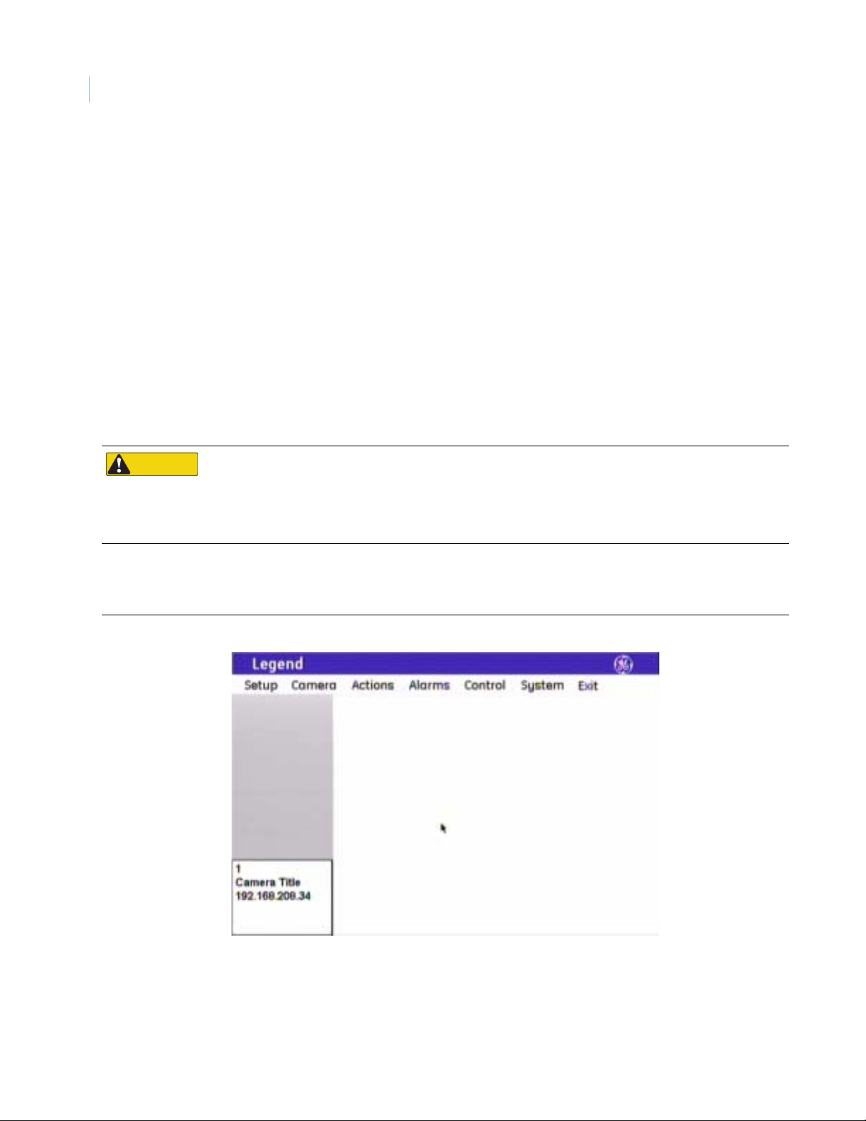
Legend is the next generation PTZ dome camera that maintains and enhances many of the features of
CyberDome that you have come to rely on. One obvious difference that you will see is that the text-based
onscreen display (OSD) programming interface has been replaced with an easy-to-use graphical programming
interface (Figure 1).
The Legend protocol is backward compatible. So you can replace older domes in an existing Digiplex system
with Legend domes. The hardware, however, is not backward compatible. Other enhancements that relate to
performance and operation include passcode protection that prevents unauthorized personnel from changing
programming settings while still allowing operator access. The dome also now offers an Ethernet connection to
flash software upgrades over a standard IP network using a standard web browser.
CAUTION
CAUTION
When flashing softwar e upg ra d e s to the do me over a standard IP network via the dome's Ethernet
connection, ensure that the netw ork is secur ed fro m unautho rized access. Lik e all Ethernet connections , the
dome's Ethernet connection has no security against unaut horized access. Y ou may consider connecting the
Ethernet cable only when you are flashing the dome, unless you have the dome connected to a secure,
isolated network.
For additional details, refer to the data sheet and the installation manual for product specifications and
installation instructions.
Figure 1. Main menu of the graphical programming interface
Page 7
Accessing the programming interface
If passcodes were turned on during installation or later, access to the programming interface will be passcodeprotected. You must log on to program the dome. Otherwise, you will be taken directly to the main
programming screen. The passcodes control who has access to the features of your dome. See Passcode screen
( Setup | Passcode ) on page 11.
The steps for accessing the programming interface from all GE keypads are similar. The following procedure is
based on the KTD-405 keypad, which is currently GE’s most popular keypad. Exceptions to the procedure for
other GE keypads are noted. You can also use the GE KTD-400 and KTD-404/304 keypads and other
manufacturers’ keypads and controllers using the PelcoD, Ultrak, Impac/485, and ASCII protocols. When
using these other protocols, all common commands used for accessing programming, operating the joystick
and iris key on the keypad, and controlling presets are supported by the Legend protocol. For an up-to-date list
of compatible keypads and protocols, please contact your GE sales representative or Technical Support.
To access the programming interface from a KTD-405 keypad:
3
1. At the normal display , press and hold the set
( ) key on the keypad until you hear a
beep and the programming code display
appears on the keypad’s LCD.
Figure 2. Normal display (visible before pr ogramming interface accessed)
CAMERA 1
MONITOR 1
2. At the enter programming code display , enter
the programming access code by pressing the
9, 5, 1, and seq keys.
Figure 3. Enter programming code display
ENTER PROGRAMMING
This code is the same for all GE keypads.
3. At the equipment selection display, press 3 to
select CAMERA (Figure 4, keypad version
1.2.09 or later) or CAMERA/RCVR
(Figure 5, keypad version 1.1.06 or earlier).
If you have an older keypad (version
1.1.06 or earlier), you will have a second
equipment selection display, at which
you need to press 1 for CYBERDOME.
Figure 5. Equipment selection display (v1.1.06 or earlier) Figure 6. Second equipment selection display for older keypads
CODE: _
Figure 4. Equipment selection display (v1.2.09 or later)
1=SWITCHER/MPLX 2=ALARMS
3=CAMERA EXIT
!
1=SWITCHER/MPLX 2=ALARMS
3=CAMERA/RCVR EXIT
!
1=CYBERDOME 2=PTZ
3=AUXILIARY
"BACK
Page 8
4
Legend
User Manual
4. At the enter site number display, enter the
number for the camera site you are
programming. This is a 3-digit number
(for example, 007, 021, 243).
You can enter one, two, or three digits
and press set ( ).
5. Continue entering commands with the
joystick.
Figure 7. Enter site number display
ENTER CAMERA SITE
NUMBER ___
Figure 8. See Monitor For Menus display
"BACK
SEE MONITOR FOR MENUS
HOLD SEQ (3 SEC) TO EXIT
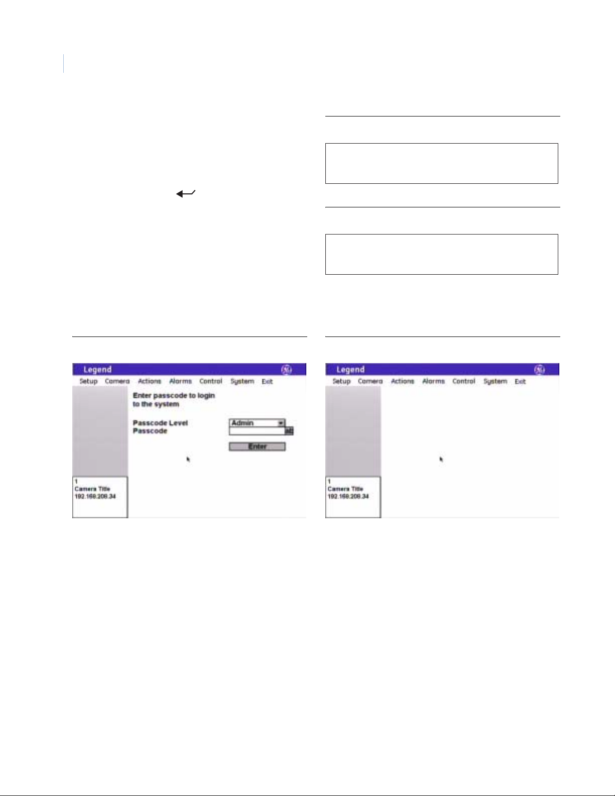
6. If passcodes are turned on, select your passcode level and enter your passcode (Figure 9). If passcodes
are turned off, you will be taken directly to the main programming screen (Figure 10).
You can now access any programming parameters that are allowed by your passcode.
Figure 9. Log on screen for the programming interface Figure 10. Main programming screen
Page 9
Navigating the programming interface
While in the programming interface, the joystick of your keypad operates in two modes depending upon what
your current action is. While moving among the menus of the programming interface, the joystick is a simulated
mouse and you enter commands using the joystick. While controlling live video, the joystick is a video controller .
So, whenever you are positioning titles or privacy masks, or programming live video features such as presets and
ShadowT ours, the joystick is a video controller, in which case, you will use the keypad’s keys to enter commands.
The timeout of the keypad controls the timeout of the programming interface. The GE KTD-405 keypad times out
after five minutes of inactivity . The programming interface will therefore time out after five minutes, as well.
On screens with tabs, be aware that the last tab accessed will be the first tab accessed the next time that you enter
that page.
Joystick as simulated mouse
When the joystick is a simulated mouse, use it as described here to enter menus and commands.
5
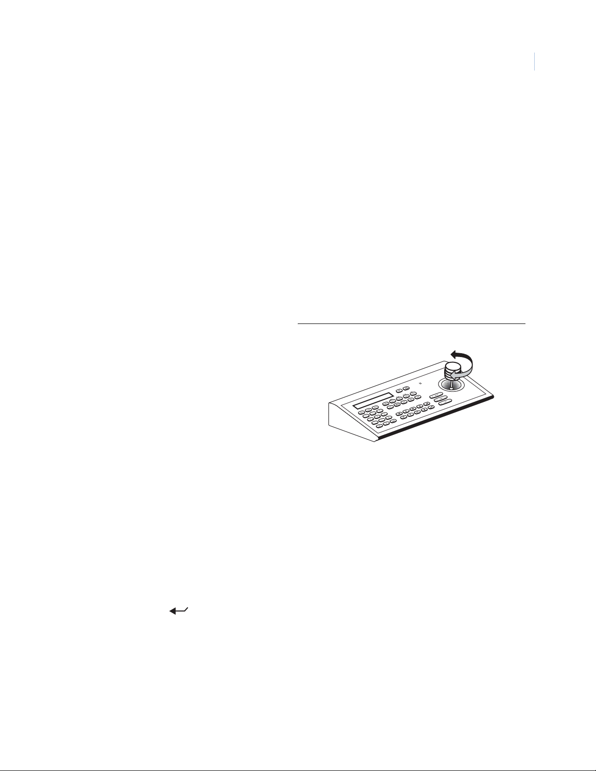
Moving the cursor (the onscreen arrow)
Figure 11. Twist the joystick knob to make selections
across the menus
To move the cursor (the onscreen arrow), push or pull
the joystick in any direction. The farther that you push
or pull, the faster the cursor will move.
Making a selection in the menus
To make a selection, place the cursor over a menu,
button, check box, item in a list, or arrow of a dropdown box, and twist the knob on the joystick.
You can also use the zoom+/- key on the keypad to
make selections.
Joystick as video controller
When the joystick is controlling video, use the keypad’s keys to enter the following programming commands.
Saving (accepting) live video programming
T o save or accept live video programming, such as positioned titles, privacy masks, presets, and ShadowTours,
press the iris + or the set ( ) key on the keypad.
Canceling (aborting) live video programming
To cancel or abort live video programming, such as positioned titles, privacy masks, presets, and
ShadowTours, press the iris - or the esc key on the keypad.
Page 10
Legend
6
User Manual
Keypad shortcuts
The following are keypad shortcut commands carried over from CyberDome programming. Where keypad
shortcuts exist for a feature, such as setting presets, you can use keys from the keypad, instead of menus from
the programming interface, to program the feature. See Table 1. You can then go into the programming
interface and customize the programmed feature with titles and other attributes.
Table 1. Keypad shortcuts (for details, see the KTD-405 Controller Keypad User Manual (1036547))
Command Keypad shortcut
Set a preset store | (number) | store
Set the left autopan limit
Set the right autopan limit
store | | store
store | | store
See Setting autopan limits on page 63 for restrictions for setting autopan limits.
Using the keyboard of the programming interface
Open the keyboard by selecting the ab icon. After you have entered the necessary characters, select Done on
the keyboard to return to the page and select OK to save the changes made to the page.
Figure 12. Using the keyboard of the programming interface
1) Select the ab icon to
open the keyboard.
3) Select the OK icon to
save changes to the page.
2) Select the Done icon to
close the keyboard.
Page 11

Basic programming
The dome is ready to operate with its defaults. Presets and ShadowTours are the most commonly used
programmable features. This section provides the step-by-step instructions for programming presets and
ShadowTours. For more challenging surveillance conditions, you can take full advantage of the dome’s
programming features. See Advanced programming on page 10.
Presets
You can set presets from the keypad or with the programming interface. If you set your presets from the keypad,
you may want to go into the programming interface to customize them with titles and exposure settings.
There are a total of 127 presets (1 through 127) that you can define for your dome. If you are using presets 62
and 63 for your left and right autopan limits, then you have a total of 125 presets that you can define.
The dome also provides the ability to remap any preset or tour command coming in from a keypad to activate
any of the 127 presets, 16 tours, or 32 macro actions. This enables you to manually initiate any of the expanded
capabilities of the dome from keypad controllers with limited command capability. See Command Map screen
( Control | Command Map ) on page 54.
7
Note: Most keypads have a limited number of preset numbers they can call. I f you have a GE KTD-405 keypad with firmware
version 1.2.09 or later, then you can call up all 127 pr eset nu mbers (1 t hr ough 12 7) directl y fr om th e key pad. If , howev er,
you have a GE KTD-405 keypad with an earlier version of firmware, then you can use the keypad to call up only the first
63 preset numbers (1 through 63). If you are using presets 62 a nd 63 for your left and right autopan limits, then you
have a total of 125 or 61 preset numbers that you can call up from the keypad. To verify your keypad’s version, press
and hold the mon key on the keypad, until the keypad beeps, then press the >> key.
Programming presets from the keypad
To program presets from the KTD-405 keypad:
1. Use the joystick to pan, tilt, and zoom the camera to the desired view.
2. Press store on the keypad.
3. Press the number keys on the keypad that correspond to the preset number you want to assign for this
position.
4. Press store again.
Note: If the keypad does not allow you to program a desired preset, you may need to change the lowest user
definable preset in the keypad program menus. Refer to the keypad manual.
5. After programming your presets, you can verify them, one at a time, by pressing the find key on the
keypad and then pressing the number keys that correspond to each preset. If you are not satisfied with
any views, you can reprogram those preset positions starting with step 1 above.
6. If desired, go into the programming interface to customize the preset with a title and exposure settings.
See Presets screen ( Actions | Presets ) on page 29.
Page 12
Legend
8
User Manual
Programming presets with the programming interface
To program presets with the programming interface:
1. Access the programming interface. (For details, see Accessing the programming interface on page 3.)
a. Press and hold the set ( ) key on the keypad until you hear a beep and the programming code
display appears on the keypad’s LCD.
b. Press the 9, 5, 1, and seq keys on the keypad.
c. Press 3 to select CAMERA.
Note: If you have an older keypad, the LCD will say CYBERDOME, instead of CAMERA, and you will have an
additional self-explanatory screen to step through.
d. Enter the number for the camera site you are programming.
The programming interface will appear on the monitor screen and you will start using the
joystick to enter commands.
e. If passcodes are turned on, select your passcode level and enter your passcode. If passcodes are
turned off, you will be taken directly to the main programming screen.
The programming interface will appear on the monitor screen and you will start using the
joystick to enter commands.
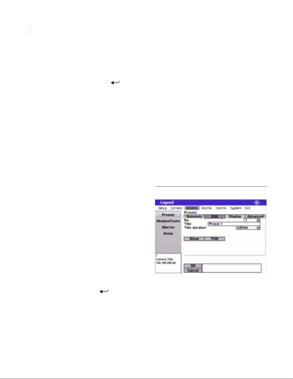
2. Select Actions by guiding the joystick to
move the cursor over the Actions menu and
Figure 13. Preset programming page ( Actions | Presets | Edit )
twisting the joystick knob.
3. Select Presets.
4. Select the Edit tab.
5. Select a preset number.
6. Select POS.
7. Use the joystick to pan, tilt, and zoom the camera to the desired view.
8. Press the iris+ or set ( ) key on the keypad to save (accept) the preset position or press the iris- or
esc key to cancel (abort) the preset position. Both cancelin g an d savin g th e preset position returns you
to the Edit page.
9. After you have saved a preset position, then you can use the other options on the Edit, Display, and
Advanced tab pages to customize the preset’s title, duration, and exposure settings. See Preset s s c reen
( Actions | Presets ) on page 29.
Page 13
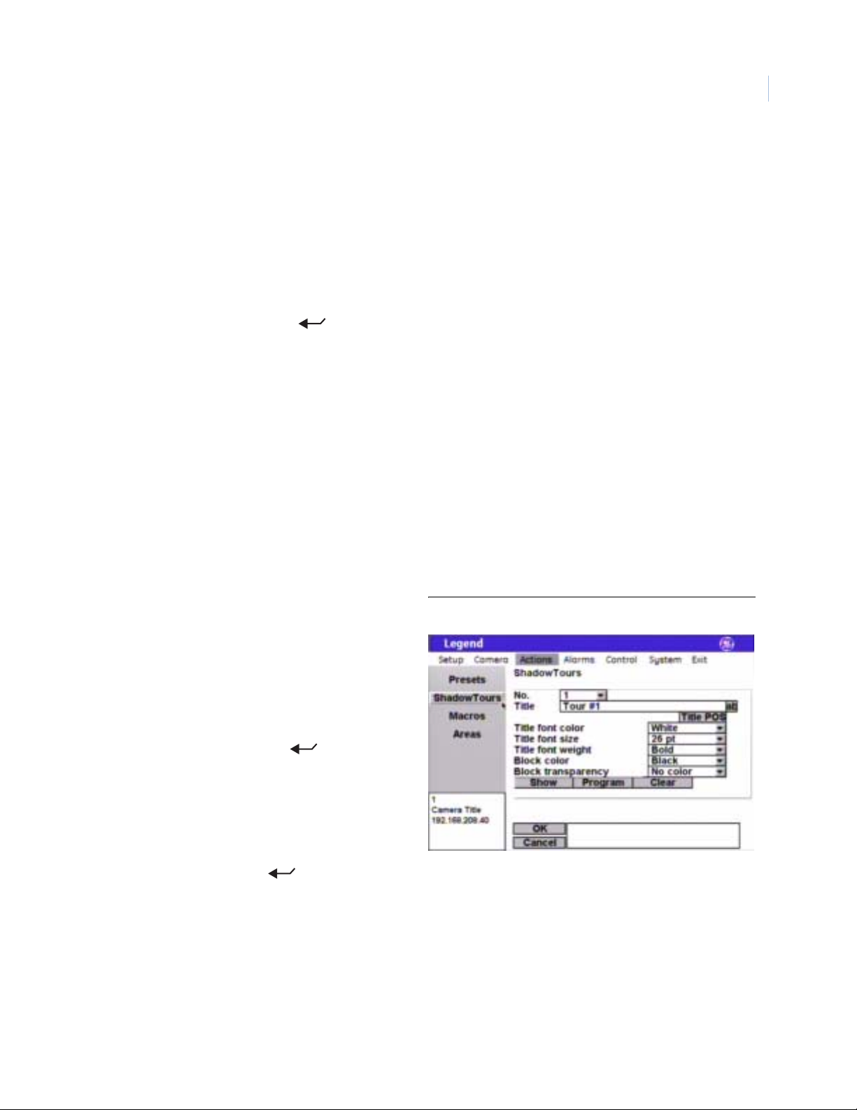
ShadowTours
You have a total of 16 ShadowTours (totaling 20 minutes) that you can define for the dome. A ShadowTour is
a tour that the camera learns by recording your manual operation of the camera. Use a keypad to manually
direct the camera through the desired PTZ movements. The camera stores those movements in memory. The
recorded tour can be replayed at any time.
To program ShadowTours with the programming interface:
1. Access the programming interface. (For details, see Accessing the programming interface on page 3).
a. Press and hold the set ( ) key on the keypad until you hear a beep and the programming code
display appears on the keypad’s LCD.
b. Press the 9, 5, 1, and seq keys on the keypad.
c. Press 3 to select CAMERA.
Note: If you have an older keypad, the LCD will say CYBERDOME, instead of CAMERA, and you will have an
additional self-explanatory screen to step through.
d. Enter the number for the camera site you are programming.
The programming interface will appear on the monitor screen and you will start using the
joystick to enter commands.
e. If passcodes are turned on, select your passcode level and enter your passcode. If passcodes are
turned off, you will be taken directly to the main programming screen.
The programming interface will appear on the monitor screen and you will start using the
joystick to enter commands.
9
2. Select Actions by guiding the joystick to
move the cursor over the Actions menu and
Figure 14. ShadowTour programming page ( Actions | ShadowTours )
twisting the joystick knob.
3. Select ShadowTours.
4. Select a ShadowTour number.
5. Select Program.
6. Press and release the set ( ) key on the
keypad to start the ShadowTour timer.
7. Use the joystick to manually direct the
camera through the desired PTZ movements
8. Press the iris+ or set ( ) key on the keypad to save (accept) the ShadowTour or press the iris- or
esc key to cancel (abort) the ShadowTour. Both canceling and saving the ShadowTour returns you to
the ShadowTour page.
9. After you have saved a ShadowTour, then you can use the other options on the ShadowTour page to
customize the tour’s title. See ShadowTours screen ( Actions | ShadowTours ) on page 38.
10. After programming your tours, you can verify them, one at a time, from within the programming
interface by selecting a tour number and Show. If you are out of the programming interface, you can
press the tour key on the keypad and the tour number to activate the desired tour.
Page 14
Legend
10
User Manual
Advanced programming
You will be using the graphical programming interface to program the dome. Keypad shortcuts do exist for
some programmable features. These keypad commands are carried over from CyberDome programming (see
Keypad shortcuts on page 6). Where keypad shortcuts exist for a feature, such as setting presets, you can use
keys from the keypad or you can use menus from the programming interface to prog ram the feature.
When changing settings on any programming page, you need to confirm the new settings by selecting OK on
that page. When establishing live video settings, you need to save the live video settings (by pressing the iris +
or the set ( ) key on the keypad) and save the changes made on the programming page (by selecting OK
in the programming interface) when you return to programming mode from live video mode.
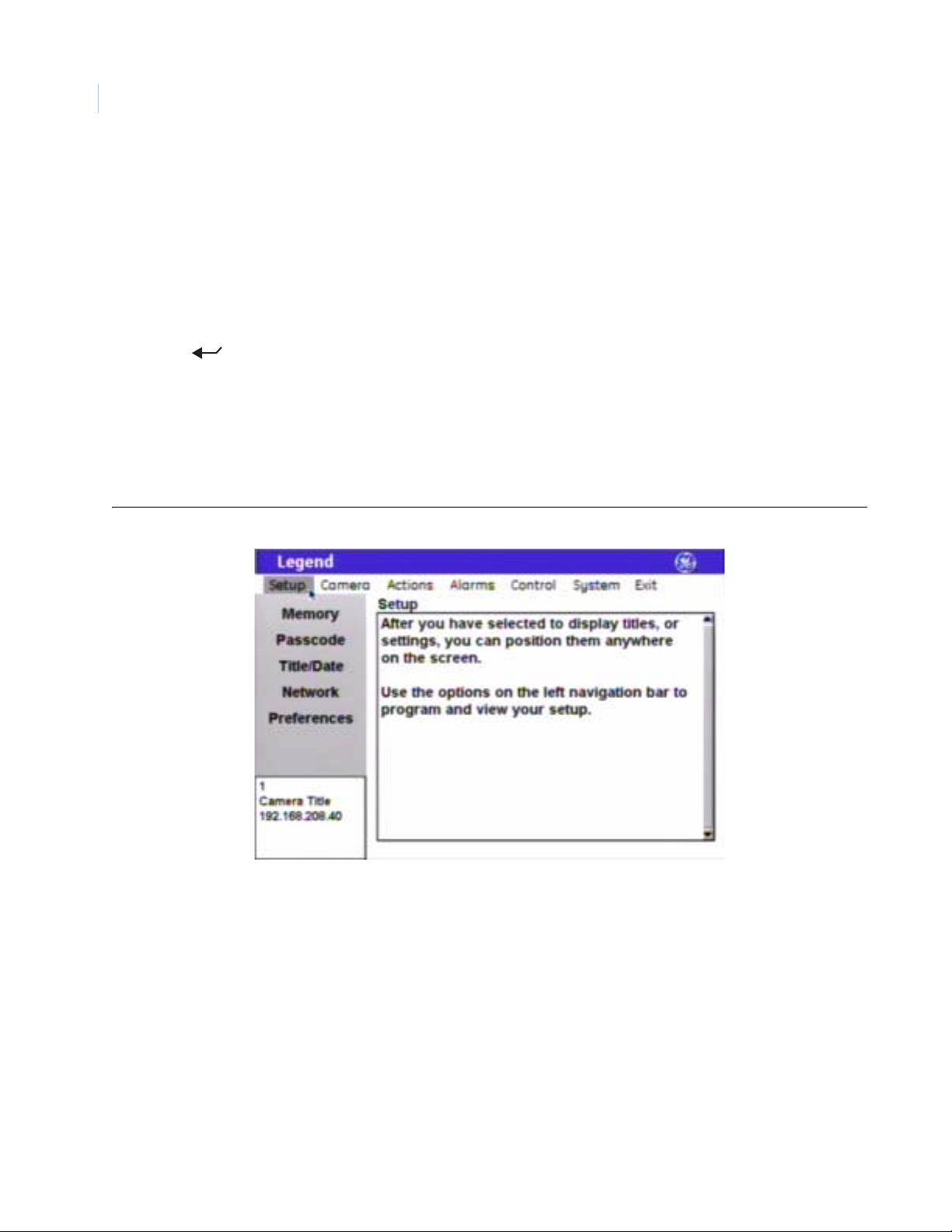
Setup menu
This is the beginning of your system’s setup. S tart here to number and title your dom e, turn on/of f or change
passcodes, establish network connectivity, set the north point, and manage your dome’s memory.
Figure 15. Setup menu
Memory screen ( Setup | Memory )
Programming and addressing for the dome are site-tied to the housing. Site-tied memory allows you to replace
cameras or move them between sites without having to reprogram cameras for each new site, because the
camera will operate using the housing memory.
The Memory screen allows you to manage your dome’s memory during setup and operation. When you clear
part or all of your dome’s memory, you are overwriting your custom programmed settings with the factory
default settings.
Page 15
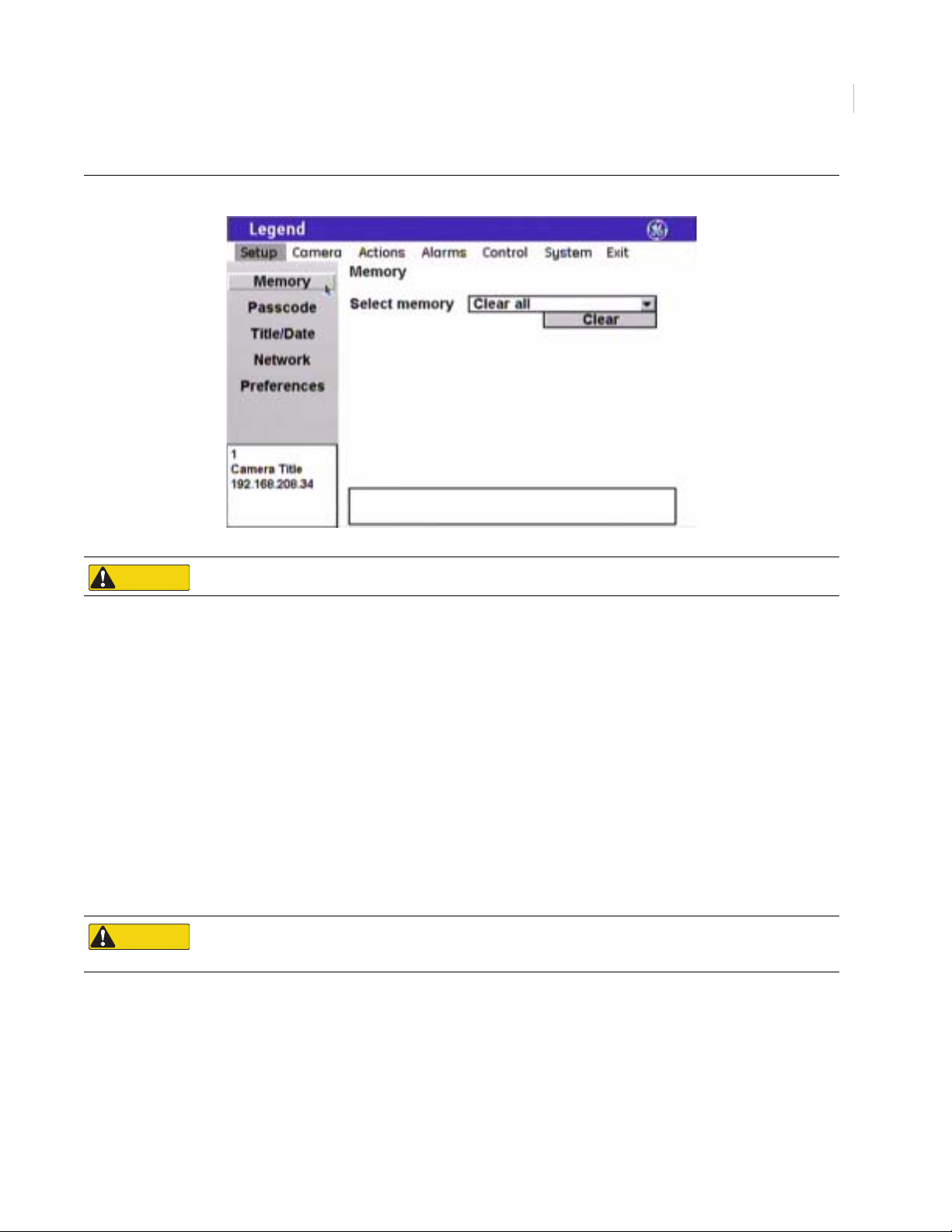
Figure 16. Memory screen ( Setup | Memory )
11
CAUTION
CAUTION
Clearing memory replaces your custom programmed settings with the factory default settings.
Select memory (clear options) You can clear all or specific portions of your dome’s programming, which is
saved in the housing’s site-tied memory. After selecting an option, select Clear.
Choices are Clear all (default), Clear setup options, Clear presets,
Clear macros, Clear ShadowTours, Clear areas, Clear alarm actions, and
Clear privacy masks.
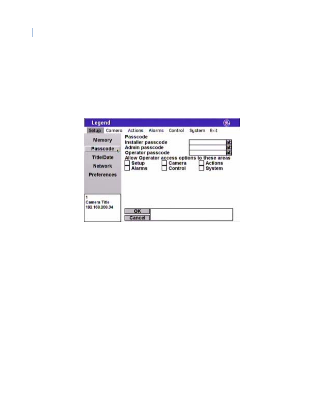
Passcode screen ( Setup | Passcode )
You can control who has access to the features of your dome by distributing passcodes that allow varying
degrees of access. The dome ships with no default passcodes. When you enter the programming interface for
the first time during installation and go to Setup | Passcode, the passcode fields are blank. Blank passcode
fields mean the passcodes are turned off (disabled). You can choose to en ter passcodes into the blanks. This
turns passcodes on (enabled) and a passcode will be required to enter the programming interface the next time
you access it.
CAUTION
CAUTION
If no passcodes are programmed, all users are given installer access and are not required to log on. If only the
Admin and Operator passcodes are programmed, then anyone can still access the entire programming interface
as an installer, since the Installer passcode was not programmed.
If using passcodes, record them in a secure place. If you forget the passcodes for a dome, you will need to
send the dome back to the factory so that it can be reset by the factory with no passcodes.
Page 16
Legend
12
User Manual
You can turn on one installer passcode, one admin passcode, and one operator passcode. They have the
following permissions:
• Installer: The installer passcode allows access to all dome features.
• Admin: The admin passcode allows access to all dome features, except passcodes and firmware updates.
• Operator: The operator passcode allows no access until it is granted access to specific features on an
area-by-area basis.
Figure 17. Passcode screen ( Setup | Passcode )
Note: Remember to select OK to save any changes you make on the page.
Installer passcode The installer passcode feature allows the installer to operate and change all
dome features, including all three default passcodes (installer, admin, and
operator). There is a 4-digit limit.
Admin passcode The admin passcode feature allows your system administrator to operate and
change all dome features, except passcodes. There is a 4-digit limit.
Operator passcode The operator passcode feature allows the operator to operate and change only
those dome features that have been enabled for the operator passcode. There
is a 4-digit limit.
Operator access options The operator access options feature allows the installer to choose which
features an operator has access to operate and change.
Choices are as shown.
Page 17
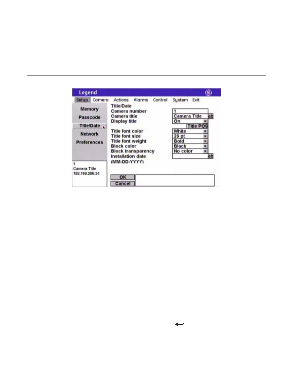
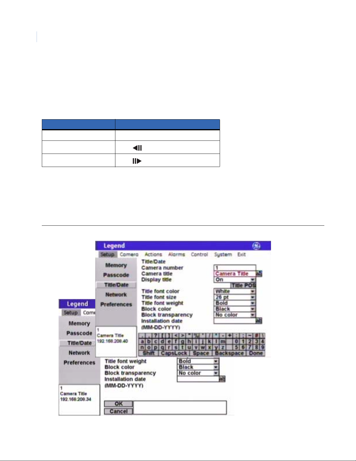
Title/Date scr een (Setup | Title/Date )
The Title/Date screen establishes the camera number, title, and installation date for the dome.
Figure 18. Title/Date screen ( Setup | Title/Date )
13
Note: Remember to select OK to save any changes you make on the page.
Camera number The programming interface reads the address number set in the camera with
the rotary address switches and displays that address as the camera number.
The camera number is not editable.
Camera title The Camera title box allows you to give your cameras unique titles. There is a
60-character limit for all titles, but be aware of how much video you want to
cover with your titles.
Display title The Display title feature enables or disables the display of individual camera
titles on the monitor screen.
Choices are On (default) and Off.
Title POS (position) The camera title will appear on screen in a default position on the monitor
screen (upper left corner), but you can reposition it with the Title POS button.
Be aware of where you already have other titles (privacy masks, presets,
tours, macros, areas, and alarms) positioned.
To set the position of the camera title:
1. Select Title POS.
2. Move the joystick to move the title to the desired position.
3. Press the iris + or the set ( ) key on the keypad to save (accept)
the new position or press the iris - or the esc key to cancel (abort) the
new position.
Title font color The camera title will appear on screen in the color selected.
Choices are as shown. Default is White.
Page 18
Legend
14
User Manual
Title font size The camera title will appear on screen in the font size selected.
Choices are as shown. Default is 26 pt.
Title font weight The camera title will appear on screen in the font weight selected.
Choices are as shown. Default is Bold.
Block color You can create a block (background) that offsets the camera title from the
video behind it. The block will appear on screen in the color selected.
Choices are as shown. Default is Black.
Block transparency You can set the block (background) to be a solid color or a transparency. The
block will appear on screen in the transparency selected.
Choices are as shown. Default is No color.
Installation date Enter the actual date of installation for your camera. Include the punctuation
in the format shown.
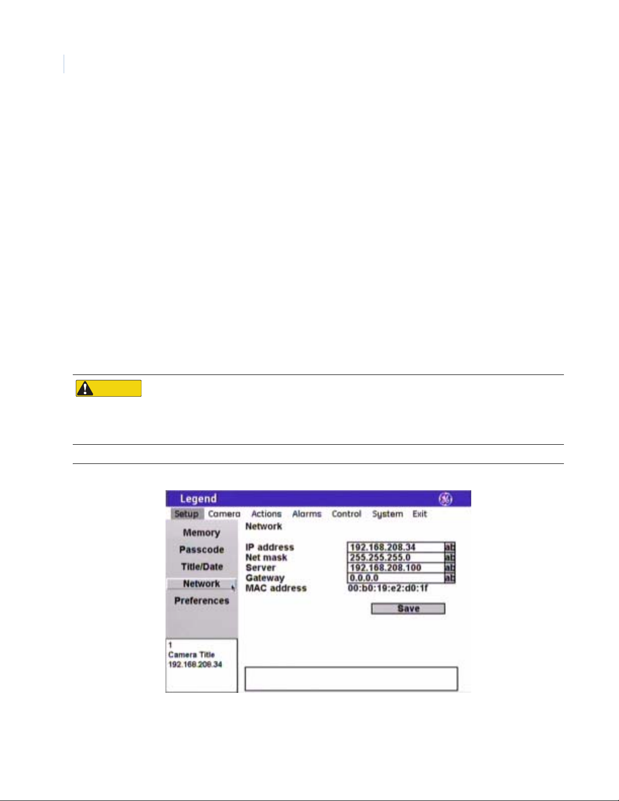
Network screen ( Setup | Network )
The Network screen establishes the IP addressing for a network connection that you can use to flash software
upgrades over a standard IP connection to the dome via its Ethernet connection.
CAUTION
CAUTION
Figure 19. Network screen (Setup | Network )
When flashing softwar e upg ra d e s to the do me over a standard IP network via the dome's Ethernet
connection, ensure that the netw ork is secur ed fro m unautho rized access. Lik e all Ethernet connections , the
dome's Ethernet connection has no security against unaut horized access. Y ou may consider connecting the
Ethernet cable only when you are flashing the dome, unless you have the dome connected to a secure,
isolated network.
IP address Enter the IP address of the dome.
Page 19
Net mask Enter the subnet mask address of the network subdivision that the dome is
assigned to.
Server Enter the IP address of the network server. If used, enter the IP address of the
TFTP host. See Firmware Update screen ( System | Firmware Update ) on
page 61.
Gateway Enter the address of the gateway between the dome and the network server.
MAC address Provided as the unique address of the dome, the MAC address allows you to
connect to the dome before you have set up its network addressing. The MAC
address is assigned at the factory. The installer establishes the overriding IP
address during installation. See the above IP address item.
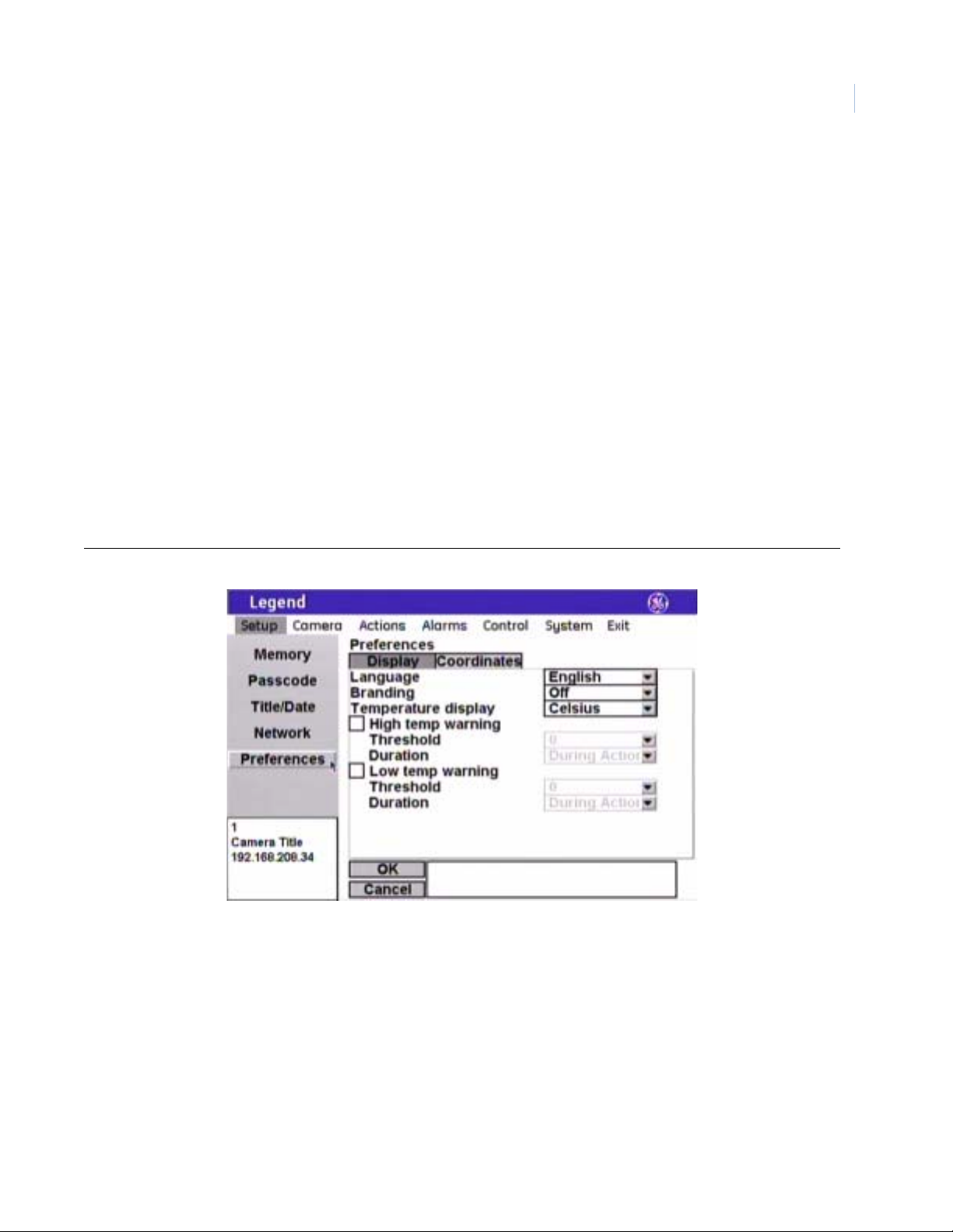
Preferences screen ( Setup | Preferences )
The Preferences screen establishes the systemwide features of language and the display of the camera’s spatial
coordinates.
Display page ( Setup | Preferences| Display)
15
Figure 20. Display page ( Setup | Preferences | Display )
Note: Remember to select OK to save any changes you make on the page.
Language The Language feature sets which language the programming interface uses to
display its content and your entries.
Choice is English.
Branding The Branding feature displays GE branding during product demonstrations.
Choices are Off (default) and On.
Temperature display The Temperature display feature sets which unit is used to display the current
operating temperature for the dome on the monitor screen.
Choices are Off (default), Celsius, and Fahrenheit.
Page 20
Legend
16
User Manual
High temp warning The High temp warning feature allows you to display a high-temperature
reading on the monitor screen when the temperature in the dome has reached
a set high threshold. Place a check mark in the check box to display this
warning. The threshold and duration features then become available.
Threshold (high-temp) The high-temperature threshold feature allows you to set the high boundary of
the allowable temperature range for the dome.
Choices range from -40 to 200 in 10-degree increments. Default is 0.
Duration (high-temp) The high-temperature duration feature allows you to set how long the warning
appears on the monitor screen.
Choices are During action (default) and Indefinite.
Low temp warning The Low temp warning feature allows you to display a low-temperature
reading on the monitor screen when the temperature in the dome has reached
a set low threshold. Place a check mark in the check box to display this
warning. The threshold and duration features then become available.
Threshold (low-temp) The low-temperature threshold feature allows you to set the low boundary of
the allowable temperature range for the dome.
Choices range from -40 to 200 in 10-degree increments. Default is 0.
Duration (low-temp) The low-temperature duration feature allows you to set how long the warni ng
appears on the monitor screen.
Choices are During action (default) and Indefinite.
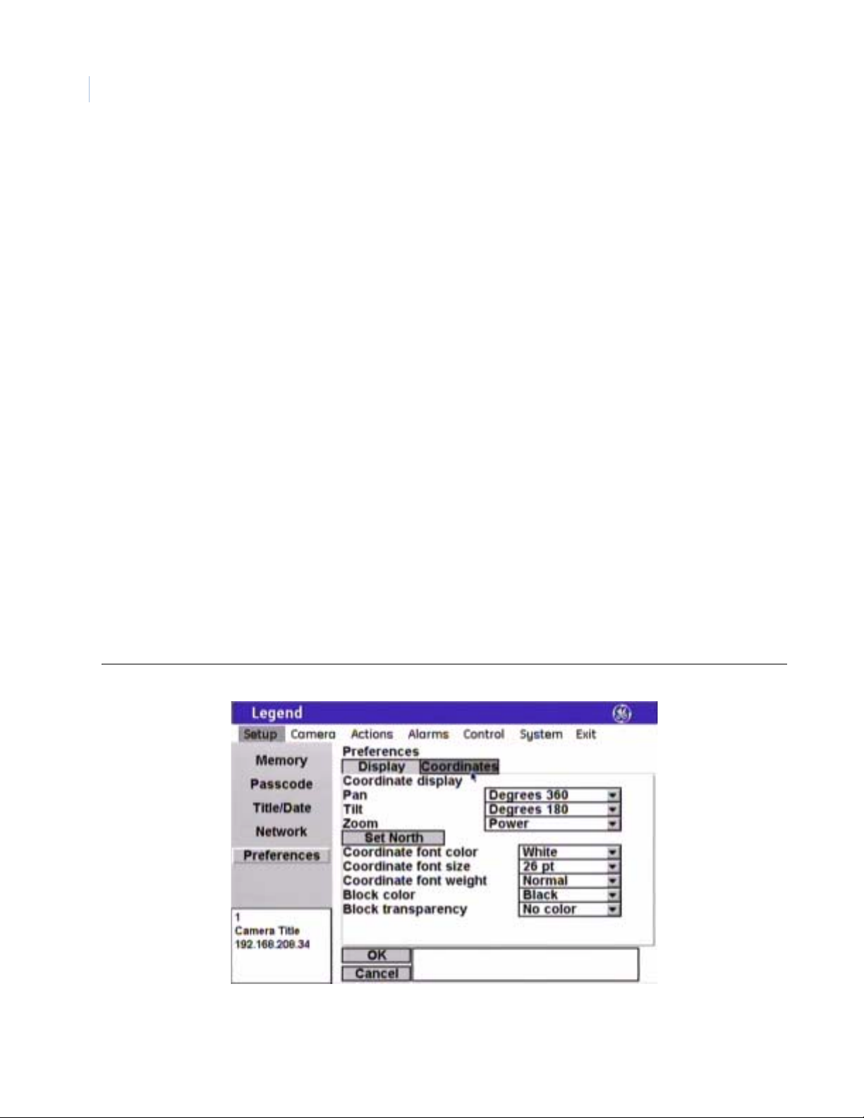
Coordinates page ( Setup | Preferences| Coordinates )
You can display the dome’s pan, tilt, or zoom coordinates on the monitor screen, if desired. Yo u can display
any or all of the coordinates. You can also choose how to display each one.
Figure 21. Coordinates page ( Setup | Preferences | Coordinates )
Note: Remember to select OK to save any changes you make on the page.
Page 21
Pan The Pan feature displays the pan coordinate of the dome.
Choices are Off, Bearings, Degrees 360 (default), and Degrees +/- 180.
Figure 22. Pan coordinates
Pan coordinates:
Bearings/Degrees 360°/Degrees ±180°
N/0°/0°
NE/45°/+45°NW/315°/-45°
W/270°/-90° E/90°/+90°
SE/135°/+135°SW/225°/-135°
S/180°/+180°
Tilt The Tilt feature displays the tilt coordinate of the dome.
Choices are Off, Degrees 180 (default), and Degrees +/- 90.
17
Figure 23. Tilt coordinates
Tilt coordinates:
Degrees 180°/Degrees ±90°
N/270°/-90°
NE/225°/-135°NW/315°/-45°
0°/+90° 180°/-90°
135°/-45°45°/+45°
90°/0°
Zoom The Zoom feature displays the zoom coordinate of the dome.
Choices are Off and Power (default).
Page 22

Legend
18
User Manual
Set north The Set north button programs the north (0°) point for the camera.
Note: When using bearings for your pan coor dinates, they are easier to interpret if you
set the true due north point as the 0° point. If, however, you are using degree pan
coordinates, you can set the 0° point anywhere along the scale. For exa mple, you
may want the 0° point to be a main entrance of a facility.
To program the north point:
1. Select Set north. The programming interface will be replaced by a
full screen of live video that asks you to aim the camera to the due
north point.
2. At the live video screen, use the joystick to pan the camera to the
desired position.
3. Press the iris + or the set ( ) key on the keypad to save (accept)
the north point or press the iris - or esc key to cancel (abort) the north
point. Both canceling and saving the north point returns you to the
Coordinates page of the Preferences screen.
Coordinate font color Coordinates will appear on screen in the color selected.
Choices are as shown. Default is White.
Coordinate font size Coordinates will appear on screen in the font size selected.
Choices are as shown. Default is 26 pt.
Coordinate font weight Coordinates will appear on screen in the font weight selected.
Choices are as shown. Default is Bold.
Block color You can create a block (background) that offsets the coordinates from the
video behind it. The block will appear on screen in the color selected.
Choices are as shown. Default is Black.
Block transparency You can set the block (background) to be a solid color or a transparency. The
block will appear on screen in the transparency selected.
Choices are as shown. Default is No color.
Page 23
Camera menu
The dome is ready to operate with its default settings. The defaults are optimized for general applications. You can
customize the dome’ s p erformance for ch allenging app lications by chang ing the dome’s camera features in the
Camera menu. One camera feature, however, is adjusted with the keys on your keypad. Backlight compensation is
adjusted with the iris control key , while you are in auto exposure mode. Backlight compensation can also be
adjusted through the programming of individual presets and tours.
Figure 24. Camera menu
19
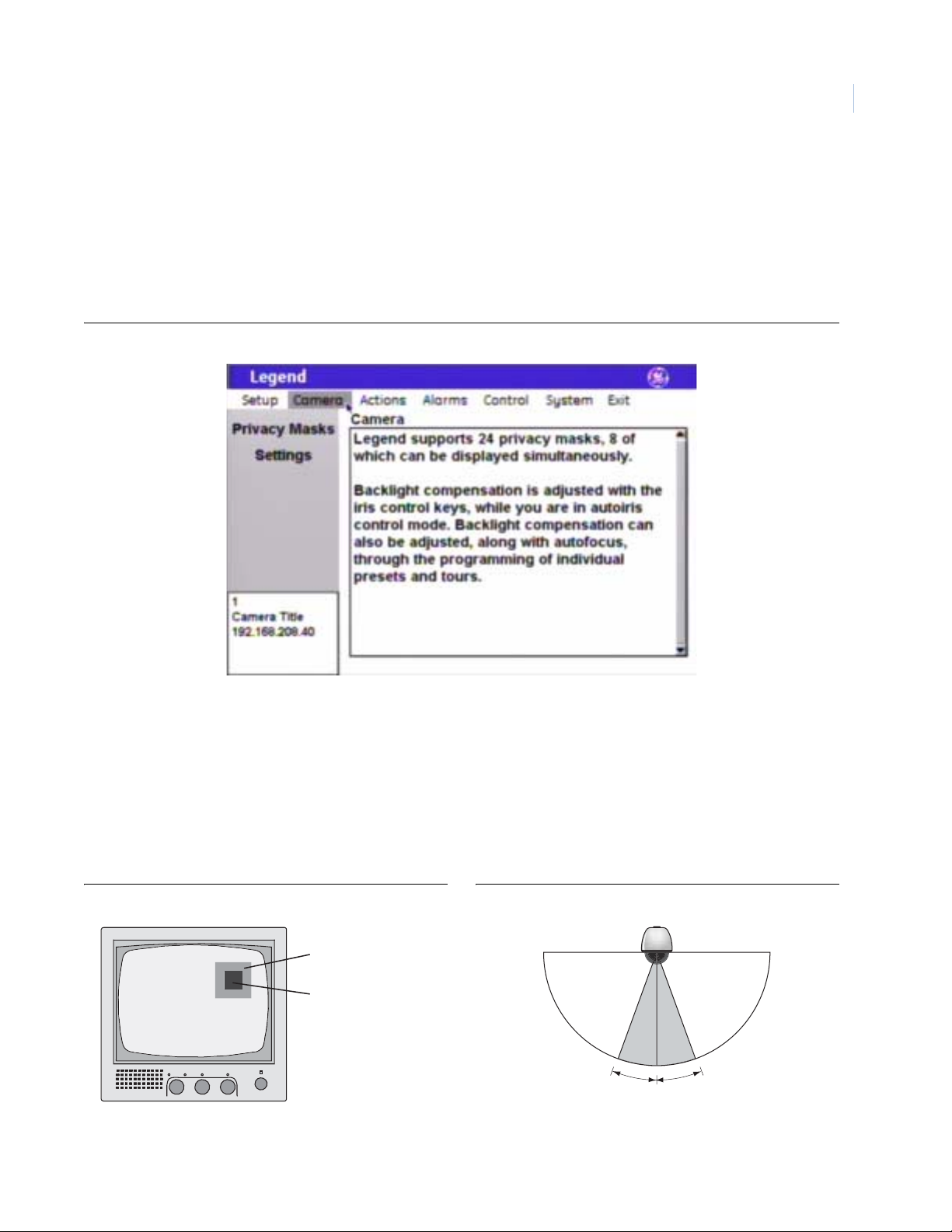
Privacy Masks screen ( Camera | Privacy Masks )
Privacy masks let you place a block over sensitive areas (such as neighboring windows) to protect them from
view on the monitor screen and in the recorded video. You can create 24 privacy masks (numbered 1 to 24) per
dome. A maximum of eight privacy masks can be displayed at on e time.
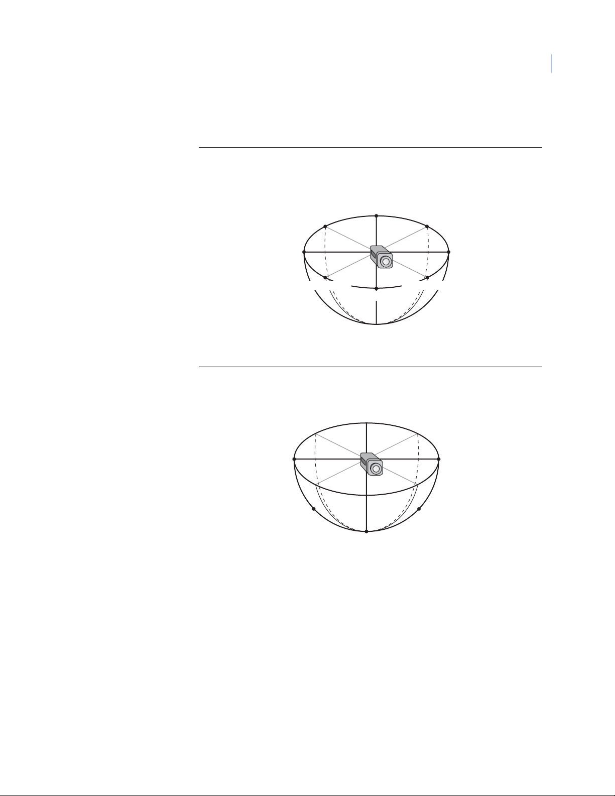
When creating your masks, it is a common practice to make them 50% larger than the areas that you wish to
cover so that the masked areas are properly covered (Figure 25).
Also be aware that masks cannot be created in the area directly below the dome (Figure 26).
Figure 25. Masks should be 50% larger than the areas to be covered Figure 26. Masks are not allowed directly below the dome
Mask
Area to be masked
No masks allowed
20° either side of 0° tilt
Page 24
Legend
20
User Manual
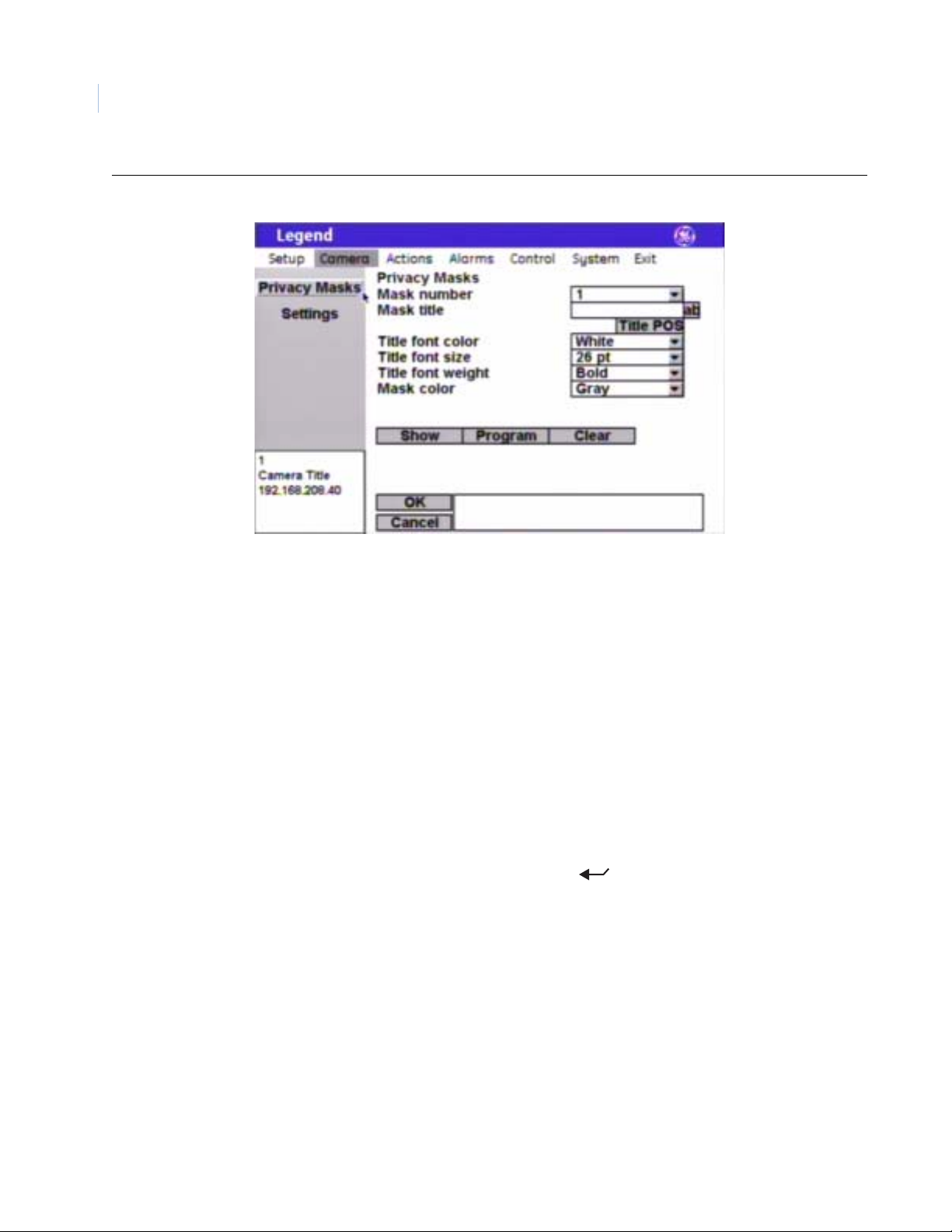
Figure 27. Privacy masks screen ( Camera | Privacy Masks )
Note: Remember to select OK to save any changes you make on the page.
Mask number The Mask number drop-down box allows you to select the mask number that
you want to program.
Mask title The Mask title box allows you to give your masks unique titles. Default
numerical titles are provided. There is a 60-character limit for all titles, but be
aware of how much video you want to cover with your titles.
Title POS The mask title will appear on screen in a default position on the monitor
screen (upper center), but you can reposition it with the Title POS button. Be
aware of where you already have other titles (camera, presets, tours, macros,
areas, and alarms) positioned.
To set the position of the mask title:
1. Select Title POS.
2. Move the joystick to move the title to the desired position.
3. Press the iris + or the set ( ) key on the keypad to accept (save)
the new position or press the iris - or esc key to cancel (abort) the new
position.
Title font color Individual mask titles will appear on screen in the color selected.
Choices are as shown. Default is White.
Title font size Individual mask titles will appear on screen in the font size selected.
Choices are as shown. Default is 26 pt.
Title font weight Individual mask titles will appear on screen in the font weight selected.
Choices are as shown. Default is Bold.
Page 25

Mask color You can customize the color of each mask. Individual masks will appear on
screen in the color selected.
Choices are Gray (default) and Red.
Show The Show button displays the mask that is currently selected by the mask
number field. The screen will say “Privacy mask preview” in the upper left
corner. Press iris +/-, esc, or set ( ) to return to the menus.
Program The Program button programs the mask. There are two screens for
programming masks. The first screen positions the camera view and the
second screen sizes the mask.
To program masks:
1. Select Program on the programming interface.
The programming interface will be replaced by a full screen of
live video overlaid with a grid that asks you to establish the center
of the privacy mask area.
2. Use the joystick to pan, tilt, and zoom the camera to the desired view .
21
3. Press the iris + or the set ( ) key on the keypad to save (accept)
the camera view or press the iris - or esc key to cancel (abort) the
camera view.
Canceling the camera view returns you to the Privacy Masks
screen. Accepting the camera view advances you to the second
mask-programming screen.
4. At the second screen (if you accepted the camera view), use the
joystick to adjust the height and width of the mask. Remember to
make the mask 50% larger than the area you want hidden.
Up increases the height, down decreases the height, left decreases
the width, and right increases the width.
5. Press the iris + or the set ( ) key to save (accept) the mask size
or press the iris - or esc key to cancel (abort) the mask.
Canceling the mask returns you to the first mask-programming
screen, where you reposition the camera view. Accepting the
mask size accepts the mask, and its size, and returns you to the
Privacy Masks screen.
Clear The Clear button deletes the mask currently assigned to the selected mask
number.
Page 26

Legend
22
User Manual
Settings screen (Camera | Settings )
Page1 page ( Camera | Settings | Page1 )
Figure 28. Page1 page ( Camera | Settings | Page1 )
Note: Remember to select OK to save any changes you make on the page.
Day/Night Day/Night is a camera feature that switches the camera mode from color
(day) to monochrome (night) and removes the IR cut filter, which increases
the camera’s sensitivity in low light. It also allows the camera to function
with IR lighting.
Note: The Day/Night feature works only if the Exposure feature is set to Auto or
Return to auto. See Interrelationship between the Exposure and Day/Night
features on page64.
Choices are Automatic (default), Manual, and Disabled.
• Automatic: Enables the camera to automatically switch between
day (color) and night (monochrome) modes at a factory default light
level. The factory default is not changeable. You can briefly override
the day/night setting from the keypad. Within a few seconds, the
dome will return to the mode (day or night) determined by the
Automatic setting.
• Manual: Allows you to manually switch the camera between day
(color) and night (monochrome) modes using a command from the
controlling device (keypad, ASCII control software, etc.).
• Disabled: Allows you to disable (turn off) both the automatic and
manual modes. There will be no switching between the day and night
modes. Switching commands from the keypad are ignored. The dome
remains in the mode that it was in when Disabled was selected.
Page 27

White balance White balance is another camera feature that compensates for lighting
conditions. It adjusts the quality of all of the colors in the video by balancing
the colors to achieve the truest white possible for the available lighting
conditions (Tungsten, fluorescent, natural). This feature is used instead of a
more general color temperature setting. To correctly set the white balance,
focus the camera on a white object.
Choices are Auto (default), Indoor, Outdoor, ATW, and Manual.
• Auto: This mode automatically adjusts the color within the 3000 to
7500 Kelvin color temperature range.
• Indoor: This mode provides you with a fixed cooler color
temperature setting.
• Outdoor: This mode provides you with a fixed warmer color
temperature setting.
• ATW (autotracking white balance): This mode automatically adjusts
the color, while the images change, within the 2000 to 10000 Kelvin
color temperature range.
• Manual: This mode allows you to manually adjust the current blue
and red settings. After selecting the Manual option, select Set to
access the red and blue scales.
• Red: This adjustment is available only if Manual white balance is
selected. Options range from 0 to 127. Default is 64.
• Move the joystick right to increase and left to decrease the
red value.
• Press the iris + or the set ( ) key on the keypad to save
(accept) the changed value or press the iris - or esc key to
cancel (abort) the changed value.
• Blue: This adjustment is available only if Manual white balance
is selected. Options range from 0 to 127. Default is 64.
• Move the joystick up to increase and down to decrease the
blue value.
• Press the iris + or the set ( ) key on the keypad to save
(accept) the changed value or press the iris - or esc key to
cancel (abort) the changed value.
Exposure settings Exposure is a camera feature that establishes what controls the light coming
into the camera through the lens. Depending on your exposure selection under
Control, one or more of the light controlling options (Autoslow shutter,
Lowest shutter speed, and Return to auto) will be available.
23
Note: The Day/Night feature works only if the Exposure feature is set to Auto or
Returnto auto. Also see Interrelationship between the Exposure and Day/Night
features on page64.
Page 28

24
Legend
User Manual
Exposure:
Control
Exposure:
Autoslow shutter
Exposure:
Lowest shutter speed
Exposure:
Return to auto
Control is an exposure feature that determines which exposure control setting
takes priority in automatic and manual operation.
Note: The Day/Night feature works only if the Exposure feature is set to Auto or
Returnto auto. Also see Interrelationship between the Exposure and Day/Night
features on page64.
Choices are Auto, Shutter, Iris (default), and Manual. See Table 2 on page 24
and Table 3 on page 25 for details about the exposure settings.
This setting is available only if the Auto control setting is selected. Autoslow
shutter is a camera feature that compensates for lighting conditions. It
automatically slows the shutter speed as the light level entering the camera
decreases so that more light can be gathered to increase image clarity. This
option works best when the camera is stationary. Because of the slowing
shutter speed, any motion in the image will begin to blur. As the light level
and the shutter speed continue to decrease, the blur of the video will gradually
increase.
Choices are Off (default) and On.
See Table 2 on page 24 and Table 3 on page 25 for details about the exposure
settings.
This setting is available only if the Shutter or Manual control setting is
selected. It sets the lowest allowable shutter speed that can be used.
Choices are as shown and are different for NTSC and PAL domes.
See Table 2 on page 24 and Table 3 on page 25 for details about the exposure
settings.
This setting is available only if the Shutter, Iris, or Manual control setting is
selected. It returns the dome to the Auto exposure mode when the camera is
manually moved.
Choices are Off and On (default).
See Table 2 on page 24 and Table 3 on page 25 for details about the exposure
settings.
Table 2. Exposure control settings
Operation
Function
controlled by the
iris keys
Backlight
compensation
(irs + for on and iris for off)
Auto Shutter Iris Manual
Exposure control setting
Shutter speed (sec) Iris setting (F-stop) First, iris setting (F-stop),
until limit reached.
Second, shutter speed
(sec), until limit reached.
Third, gain (dB).
Page 29

Table 2. Exposure control settings
25
Exposure control setting
Operation
Automatic
adjustments
•Iris setting (F-stop)
• Shutter speed (sec)
Auto Shutter Iris Manual
• Iris setting (F-stop)
•Gain (dB)
•Gain (dB)
Except when the
shutter speed is
below 1/60s NTSC or
1/50s PAL.
Available controls Autosl o w sh ut ter • Lowest shutter speed
• Return to auto
Table 3. Exposure options
Exposure option
Operation
Available for
which control
Autoslow shutter Lowest shutter speed Return to auto
Auto • Shutter
•Manual
setting
How it works Automatically slows the
shutter speed below the
Sets the lowest allowable
shutter speed.
normal setting as needed
to compensate for low-light
conditions.
• Shutter speed (sec)
N/A
•Gain (dB)
Return to auto • Lowest shutter speed
• Return to auto
•Shutter
•Iris
•Manual
Returns the dome to Auto exposure mode
with any manual pan or tilt movement.
Thereby returning the iris toggle key to
function as a control for the shutter speed,
iris setting, or gain, depending on the
exposure mode selected.
Page 30

Legend
26
User Manual
Page2 page ( Camera | Settings | Page2 )
Figure 29. Page2 page ( Camera | Settings | Page1 )
Note: Remember to select OK to save any changes you make on the page.
Phase lock enabled Phase lock enabled is a camera feature that allows synchronization of the
video signal to reduce the effect of picture roll on analog video switchers.
By default, the phase lock is off. As such, each camera is synchronizing its
video signal to its own internal clock crystal. This is called internal
synchronization. If you enable phase lock (select On), you are selecting what
is called line lock synchronization and the camera will synchronize its video
signal to the AC input voltage. With line lock synchronization, you also adjust
the vertical phase shift of a camera’s video signal to coordinate with other
cameras. Due to differences in cameras, environments, and cable lengths, the
phase shift will not be the same for all cameras being synchronized. Use an
oscilloscope or a GE Security vertical phase adjustment tool (KTS-56).
Contact your GE Security sales representative.
Phase adjustment This option is available only if On is selected for Phase lock enabled.
Choices range from 0 to 127°. Default is 50°. These settings map to the 0 to
360° angle adjustment range. Use your oscilloscope or vertical phase
adjustment tool to verify settings.
Stabilization Stabilization is a camera feature that reduces video shaking for cameras that
are located in areas prone to vibration. It works best for low frequency
vibration (3 to 10 Hz). If it is available for your camera, it creates a slight lag
and movement backward when a pan/tilt movement stops
Choices are Off and On.
Page 31

Digital zoom limit Digital zoom is an electronic camera feature that increases the apparent size
of images beyond the magnification of the camera’s optical lens. Because
image information is not also increased, there is some loss of image
resolution. So test the different settings for suitability. Selecting too high of a
digital zoom can result in the loss of video clarity for some scenes. To test:
Select a setting and use your keypad’s zoom key to zoom in and out.
Choices range from 1x to 12x (default).
Lift Lift is a camera feature that optimizes the video’s color over long runs of
coaxial cable.
Use the joystick to adjust the lift. Right increases and left decreases the lift.
Choices range from 0 to 7. Default is 0.
27
CAUTION
CAUTION
Lift and gain compensate for long runs of video coaxial cable.
Only qualified personnel should adjust these settings. Incorrect
adjustments can impair video quality.
Gain Gain is a camera feature that optimizes the video’s brightness over long runs
of coaxial cable. Gain increases the video signal’s amplitude to increase the
brightness of darkened video and to reduce the noise of weakened video.
Use the joystick to adjust the gain. Up increases and down decreases the gain.
Choices range from 0 to 31. Default is 0.
CAUTION
CAUTION
Lift and gain compensate for long runs of video coaxial cable.
Only qualified personnel should adjust these settings. Incorrect
adjustments can impair video quality.
Zoom speed Zoom speed is a camera feature that sets the rate at which the zoom motors
operate. There are three fixed settings and one variable setting. If your keypad
provides variable-speed control for zooming, you can use the Variable setting
and the joystick's range of motion for operation. You quicken or slow the
zoom by how far you twist the joystick. Farther is faster.
Choices are Variable (default), Slow, Medium, and Fast.
Tilt up limit Tilt up limit is a feature that sets a programmable stop for the camera at the
highest point that you want it to tilt up.
By default, the pan and tilt limits are off. Programming them turns them on.
Note: The dome prevents any hourglassing behavior by restricting the tilt limit to 90°,
when necessary, to accommodate some pan limits set to less than 180°. To avoid
setting tilt limits too tightly, we recommend that you set the pan limits first, then
set the tilt limits.
Page 32

Legend
28
User Manual
Tilt down limit Tilt down limit is a feature that sets a programmable stop for the camera at the
lowest point that you want it to tilt down.
By default, the pan and tilt limits are off. Programming them turns them on.
Note: The dome prevents any hourglassing behavior b y restricting the tilt limit to 90° ,
when necessary, to accommodate some pan limits set to less than 180°. To avoid
setting tilt limits too tightly, we recommend that you set the pan limits first, then
set the tilt limits.
Pan left limit Pan left limit is a feature that sets a programmable stop for the camera at the
leftmost point that you want it to pan left.
By default, the pan and tilt limits are off. Programming them turns them on.
Note: The dome prevents any hourglassing behavior b y restricting the tilt limit to 90° ,
when necessary, to accommodate some pan limits set to less than 180°. To avoid
setting tilt limits too tightly, we recommend that you set the pan limits first, then
set the tilt limits.
Pan right limit Pan right limit is a feature that sets a programmable stop for the camera at the
rightmost point that you want it to pan right.
By default, the pan and tilt limits are off. Programming them turns them on.
Note: The dome prevents any hourglassing behavior b y restricting the tilt limit to 90° ,
when necessary, to accommodate some pan limits set to less than 180°. To avoid
setting tilt limits too tightly, we recommend that you set the pan limits first, then
set the tilt limits.
Clear limits Clear limits is a feature that clears all programmable stops that have been set
for the camera.
Page 33

Actions menu
You can program a variety of custom actions for each dome. Your custom actions include 127 preset positions,
16 ShadowTours, 32 macros, and 120 areas. You can edit the title and description of any action and you can
reassign the positions of existing presets.
The keypad’s joystick will function as a simulated mouse or video controller at different times during the
programming of your actions.
Figure 30. Actions menu
29
Presets screen (Actions |Presets )
There are a total of 127 presets (1 through 127) that you can define for your dome. If you are using presets 62
and 63 for your left and right autopan limits, then you have a total of 125 presets that you can define.
The dome also provides the ability to remap any preset or tour command coming in from a keypad to activate
any of the 127 presets, 16 tours, or 32 macro actions. This enables you to manually initiate any of the expanded
capabilities of the dome from keypad controllers with limited command capability. See Command Map screen
( Control | Command Map ) on page 54.
Note: Most keypads have a limited number of preset numbers they can call. I f you have a GE KTD-405 keypad with firmware
version 1.2.09 or later, then you can call up all 127 pr eset nu mbers (1 t hr ough 12 7) directl y fr om th e key pad. If , howev er,
you have a GE KTD-405 keypad with an earlier version of firmware, then you can use the keypad to call up only the first
63 preset numbers (1 through 63). If you are using presets 62 a nd 63 for your left and right autopan limits, then you
have a total of 125 or 61 preset numbers that you can call up from the keypad. To verify your keypad’s version, press
and hold the mon key on the keypad, until the keypad beeps, then press the >> key.
Page 34

Legend
30
User Manual
Summary page (Actions|Presets|Summary)
The summary page provides the number and title of all 127 presets (1 through 127) that are available for the
dome, whether or not they are programmed or titled.
Figure 31. Summary page ( Actions | Presets | Summary )
No. The No. column of the summary page lists all 127 presets (1 through 127) in
numerical order, whether or not they are programmed.
Title The Title column of the summary page lists the titles of all 127 presets. The
default titles are listed if they have not been retitled.
Page 35

Edit page (Actions|Presets|Edit)
The Edit page is where you program your presets. You can select any preset number, whether previously
programmed with a preset position or not. You can reassign new positions to existing presets. After you have
selected a number and established the duration of the preset title, you will select the POS button and program the
preset position. After setting the position, you can use the Display and Advanced pages to program additional
characteristics for the preset such as title and specific exposure modes, if needed.
Figure 32. Edit page ( Actions | Presets | Edit )
31
Note: Remember to select OK to save any changes you make on the page.
No. The No. drop-down box allows you to select the preset number that you want
to program or reprogram.
Title The Title box shows you the existing title for the selected preset number. You
can customize the default title on the Display page.
Duration The Duration feature defines how long the preset title appears on the monitor
screen.
Choices are Infinite (default) and 5 to 120 seconds in 5-second increments.
Show The Show button displays the preset that is currently selected by the preset
number option. The screen will say “Show preset” in the upper left corner.
Press iris +/-, esc, or set ( ) to return to the menus.
Page 36

Legend
32
User Manual
POS (position) The POS (position) button programs the preset. There is one screen for
programming presets.
To program a preset:
1. Select POS. The programming interface will be replaced by a
full screen of live video that asks you to set the desired position for
the preset.
2. At the live video screen, use the joystick to pan, tilt, and zoom the
camera to the desired position.
3. Press the iris + or the set ( ) key on the keypad to save (accept)
the preset position or press the iris - or esc key to cancel (abort) the
preset position. Both cancelling and saving the preset position returns
you to the Edit page of the Presets screen.
Display page (Actions|Presets|Display)
Figure 33. Display page ( Actions | Presets | Display )
Note: Remember to select OK to save any changes you make on the page.
No. The No. drop-down box allows you to select the preset number that you want
to continue programming.
Title The Title box allows you to give your presets unique titles. Default numerical
titles are provided. There is a 60-character limit for all titles, but be aware of
how much video you want to cover with your titles.
Page 37

Title POS The preset title will appear on screen in a default position on the monitor
screen (bottom center), but you can reposition it with the Title POS button. Be
aware of where you already have other titles (camera, privacy masks, tours,
macros, areas, and alarms) positioned.
To set the position of the preset title:
1. Select Title POS.
2. Move the joystick to move the title to the desired position.
3. Press the iris + or the set ( ) key on the keypad to save (accept)
the new position or press the iris - or esc key to cancel (abort) the new
position.
Display title on screen The Display title on screen feature sets the preset title to appear on the
monitor screen, if checked. The duration that the title appears on the monitor
screen is set by the Duration feature on the Edit page.
Title font color The preset title will appear on screen in the color selected.
Choices are as shown. Default is White.
Title font size The preset title will appear on screen in the font size selected.
Choices are as shown. Default is 26 pt.
Title font weight The preset title will appear on screen in the font weight selected.
Choices are as shown. Default is Bold.
Block color Y ou can create a block (background) that offsets the preset title from t he video
behind it. The block will appear on screen in the color selected.
Choices are as shown. Default is Black.
Block transparency You can set the block (background) to be a solid color or a transparency. The
block will appear on screen in the transparency selected.
Choices are as shown. Default is No color.
33
Advanced page (Actions|Presets|Advanced)
The Advanced page of the Presets screen (under the Actions menu) allows you to change a camera’s feature
settings for the duration of individual presets.
Page 38

Legend
34
User Manual
Figure 34. Advanced page ( Actions | Presets | Advanced )
Note: Remember to select OK to save any changes you make on the page.
No. The No. drop-down box allows you to select the preset number that you want
to continue programming.
Title The Title box shows you the existing title for the selected preset number. You
can customize the default title on the Display page.
Use custom camera state for
preset
The Use custom camera state for preset feature overrides the settings
established for the camera’s normal operation under Camera | Settings, if
checked. You must check this feature to make the other features on this screen
available.
Page 39

Night mode For the duration of this preset, you can change the camera’s Day/Night setting.
Day/Night is a camera feature that switches the camera mode from color (d ay)
to monochrome (night) and removes the IR cut filter , which increases the
camera’s sensitivity in low light. It also allows the camera to function with IR
lighting. It is programmed under Camera | Settings (see Settings scr een
( Camera | Settings ) on page 22).
Note: The Day/Night feature works only if the Exposure feature is set to Auto or
Return to auto. See Interrelationship between the Exposure and Day/Night
features on page64.
When you turn on the Night mode feature, you are telling the camera to override
the normal operating setting as follows:
• Automatic: If the Day/Night feature is set to Automatic under
Camera | Settings, then the Night mode feature will use the Day/Night
setting customized for the preset for 5 to 10 seconds. After 5 to 10
seconds, the camera will revert to the normal operating setting and
adjust for the current light conditions.
• Manual: If the Day/Night feature is set to Manual under
Camera | Settings, then the Night mode feature will use the Day/Night
setting customized for the preset until the preset is left. After the preset
is left, the camera will revert to the Day/Night setting that it was using
before the preset was called.
• Disabled: If the Day/Night feature is set to Manual under
Camera | Settings, then the Night mode feature will do nothing.
Choices are Off (default) and On.
35
Backlight For the duration of this preset, you can change the camera's Backlight
compensation setting. Backlight compensation is a feature that illuminates the
display so that the foreground appears sharper in contrast with the background .
Choices are Off (default) and On.
Page 40

Legend
36
User Manual
White (white balance) For the duration of this preset, you can change the camera’s White balance
setting. White balance is a the feature that compensates for lighting
conditions. It adjusts the quality of all of the colors in the video by balancing
the colors to achieve the truest white possible for the available lighting
conditions (Tungsten, fluorescent, natural). This feature is used instead of a
more general color temperature setting. To correctly set the white balance,
focus the camera on a white object.
Choices are Auto (default), Indoor, Outdoor, ATW, and Manual.
• Auto: This mode automatically adjusts the color within the 3000 to
7500 Kelvin color temperature range.
• Indoor: This mode provides you with a fixed cooler color
temperature setting.
• Outdoor: This mode provides you with a fixed warmer color
temperature setting.
• ATW (autotracking white balance): This mode automatically adjusts
the color, while the images changes, within the 2000 to 10000 Kelvin
color temperature range.
• Manual: This mode allows you to manually adjust the current blue
and red settings. After selecting the Manual option, select Set to
access the red and blue scales.
• Red: This adjustment is available only if Manual white balance is
selected. Options range from 0 to 127 (default is 64).
• Push the joystick right to increase and left to decrease the
red value.
• Press the iris + or the set ( ) key on the keypad to save
(accept) the changed value or press the iris - or esc key to
cancel (abort) the changed value.
• Blue: This adjustment is available only if Manual white balance
is selected. Options range from 0 to 127 (default is 64).
• Push the joystick up to increase and down to decrease the
blue value.
• Press the iris + or the set ( ) key on the keypad to save
(accept) the changed value or press the iris - or esc key to
cancel (abort) the changed value.
Page 41

Exposure For the duration of this preset, you can change the camera’s Exposure setting.
Exposure is a feature that establishes what controls the light coming into the
camera through the lens.
Note: The Day/Night feature works only if the Exposure feature is set to Auto or
Return to auto. See Interrelationship between the Exposure and Day/Night
features on page64.
Choices are Auto (default), Shutter, Iris, and Manual.
• Auto: Selecting this feature makes the camera determine what
features (iris aperture, gain, shutter speed, or combination thereof)
control the incoming light. You will not be able to set values for iris,
gain, or shutter speed.
• Shutter: The set shutter speed controls the length of time that the
aperture is open to let light into the camera through the lens. You will
not be able to set values for iris or gain. The choices for shutter speed
are as shown.
Use the zoom +/- key on the keypad to scroll through the choices,
then press the iris + or the set ( ) key on the keypad to save
(accept) the changed value or press the iris - or esc key to cancel
(abort) the changed value.
37
• Iris: The set iris F-stop controls the size of the aperture that lets light
into the camera through the lens. You will not be able to set values for
gain or shutter speed. The choices for iris F-stop are as shown.
Use the zoom +/- key on the keypad to scroll through the choices,
then press the iris + or the set ( ) key on the keypad to save
(accept) the changed value or press the iris - or esc key to cancel
(abort) the changed value.
• Manual: You control the light coming into the camera through the
lens by setting specific values for iris, gain, and shutter speed. The
choices are as shown. After selecting the Manual option, select Set to
access each shutter, iris, and gain controls. The choices for each are as
shown.
Use the zoom +/- key on the keypad to scroll through the choices,
then press the iris + or the set ( ) key on the keypad to save
(accept) the changed value or press the iris - or esc key to cancel
(abort) the changed value.
Page 42

Legend
38
User Manual
ShadowTours screen (Actions | ShadowTours )
You have a total of 16 ShadowTours (totaling 20 minutes) that you can define for the dome.
Figure 35. ShadowTours screen ( Actions | ShadowTours )
Note: Remember to select OK to save any changes you make on the page.
No. The No. drop-down box allows you to select the ShadowTour nu mber that you
want to program.
Title The Title box allows you to give your ShadowTours unique titles. Default
numerical titles are provided. There is a 60-character limit for all titles, but be
aware of how much video you want to cover with your titles.
Title POS The ShadowTour title will appear on screen in a default position on the
monitor screen (center, above the macro title default position), but you can
reposition it with the Title POS button. Be aware of where you already have
other titles (camera, privacy masks, presets, macros, areas, and alarms)
positioned.
To set the position of the preset title:
1. Select Title POS.
2. Move the joystick to move the title to the desired position.
3. Press the iris + or the set ( ) key on the keypad to accept (save)
the new position or press the iris - or esc key to cancel (abort) the new
position.
Title font color The ShadowTour title will appear on screen in the color selected.
Choices are as shown. Default is White.
Title font size The ShadowTour title will appear on screen in the font size selected.
Choices are as shown. Default is 26 pt.
Page 43

Title font weight The ShadowTour title will appear on screen in the font weight selected.
Choices are as shown. Default is Bold.
Block color You can create a block (background) that offsets the ShadowTour title from
the video behind it. The block will appear on screen in the color selected.
Choices are as shown. Default is Black.
Block transparency You can set the block (background) to be a solid color or a transparency. The
block will appear on screen in the transparency selected.
Choices are as shown. Default is No color.
Show The Show button displays the ShadowTour that is currently selected by the
ShadowTour number field. Press iris +, esc, or set ( ) to return to the
menus.
Note: Since the GE KTD-405 keypad times out after five minutes of inactivity and the
programming interface times out along with it, you will want to exit the
programming interface to view ShadowTours that are longer than five minutes.
Program The Program button programs the ShadowTour.
To program a ShadowTour:
39
1. Select Program. The programming interface will be replaced by a
full screen of live video.
2. At the live video screen, press the iris + or the set ( ) key on
the keypad to set the starting point of the ShadowTour, then use the
joystick to pan, tilt, and zoom the camera through the desired views.
3. Press the press the iris + or the set ( ) key on the keypad to save
(accept) the ShadowTour or press the iris - or esc key to cancel
(abort) the ShadowTour.
Clear The Clear button deletes the ShadowTour currently assigned to the selected
ShadowTour number.
Page 44

Legend
40
User Manual
Macros screen ( Actions | Macros )
You can program 32 macros per dome. Macros are any preset tour or programmed routine. Each macro can
contain up to 16 steps. The step, type, and type number options will appear on all macro programming screens.
The step type determines what additional options are available for programming.
Program page (Actions|Macros|Program)
Figure 36. Program page ( Actions | Macros | Program )
Note: Remember to select OK to save any changes you make on the page.
No. The No. drop-down box allows you to select the macro number that you want
to program.
Title The Title box shows you the existing title for the selected macro number. You
can customize the default title on the Display page.
Macro list
(step, type, no., speed,
zoom, and duration)
The macro list shows the defined steps for the macro in sequential order. You
can use the drop-down boxes and buttons located below the summary to add
(append), delete (remove), move up, or move down individual steps.
Step (number) The Step box selects the step number you want to program.
Type The Type box selects the action for the selected step. It determines what
additional options appear (are available) for programming.
Choices are Preset (default), Tour, Macro, Relay, and Jump (jumps to a prior
step).
Type #
(e.g., preset number)
The Type # option selects which of the group (for example, presets) is to be
assigned to the step. The type number changes its name depending on the type
selected under Type (Preset, Tour, Macro, Relay, or Jump).
# Repeats (with Jump) The # Repeats option allows you to repeat a jump step up to 49 times.
Page 45

Speed (with Preset or Tour) The Speed option allows you to set how fast the camera will move to the
preset step.
Choices are Slow, Medium, Fast, and Max.
Transition (with Preset or Tour)The Transition option allows you to set how the video will be seen on the
monitor screen during a preset step.
Choices are Freeze (default) and Zoom out.
• The Freeze feature freezes the last image on the monitor screen while
the camera is moving. A static image will show on the monitor screen
until the camera stops.
• The Zoom out feature zooms the camera out before it moves, remains
zoomed out during travel, and reestablishes the set zoom when it
arrives at its destination.
Duration (if Preset selected) The Duration feature defines how long the action for the step continues. For
presets, the duration is the dwell time that the camera remains at a preset
before continuing on to the next macro step.
Choices are 1 to 60 seconds in 1-second increments.
41
Duration (if Relay selected) The Duration feature defines how long the action for the step continues. For
relays, the duration is a timer for the relay action. The next macro step is
immediately performed after the relay timer runs out.
Choices are Infinite (default) and seconds (1, 2, 3, 4, 5, 15, 30, and 60).
Energize (with Relay) The Energize option, if checked, sets the relay to its energized state. Which is
closed for a normally open connection and open for a normally closed
connection.
Display title (checkbox) The Display title feature sets the macro title to appear on the monitor screen,
if checked.
Append The Append button adds one step to the bottom of the list of macro steps.
Remove The Remove button deletes the currently selected step.
Move up The Move up button moves the currently selected step up one step number in
the macro sequence each time it is selected.
Move down The Move down button moves the currently selected step down one step
number in the macro sequence each time it is selected.
Page 46

Legend
42
User Manual
Display page ( Actions | Macros | Display )
Figure 37. Display page ( Actions | Macros | Display )
Note: Remember to select OK to save any changes you make on the page.
No. The No. drop-down box allows you to select the macro number that you want
to continue programming.
Title The Title box allows you to give your macros unique titles. Default numerical
titles are provided. There is a 60-character limit for all titles, but be aware of
how much video you want to cover with your titles.
Title POS The macro title will appear on screen in a default position on the monitor
screen (center, below the tour title default position), but you can reposition it
with the Title POS button. Be aware of where you already have other titles
(camera, privacy masks, presets, tours, areas, and alarms) positioned.
To set the position of the macro title:
1. Select Title POS.
2. Move the joystick to move the title to the desired position.
3. Press the iris + or the set ( ) key on the keypad to accept (save)
the new position or press the iris - or esc key to cancel (abort) the new
position.
Title font color The macro title will appear on screen in the color selected.
Choices are as shown. Default is White.
Title font size The macro title will appear on screen in the font size selected.
Choices are as shown. Default is 26 pt.
Title font weight The macro title will appear on screen in the font weight selected.
Choices are as shown. Default is Bold.
Page 47

Block color You can create a block (background) that offsets the ShadowTour title from
the video behind it. The block will appear on screen in the color selected.
Choices are as shown. Default is Black.
Block transparency You can set the block (background) to be a solid color or a transparency. The
block will appear on screen in the transparency selected.
Choices are as shown. Default is No color.
Areas screen ( Actions | Areas )
Areas are similar to privacy masks. Both hide areas designated as sensitive. But whereas privacy masks cover
only a portion of the video displayed, areas hide all of it. Areas replace the video with a blue screen when the
camera passes the center point of a marked area. You can also display the title on the monitor screen of a
designated area without blanking the video with a blue screen. You can create 120 areas.
When creating your masks, be aware that they are triggered by their center viewpoint. Therefore, it is a
common practice to make masks twice the size of the area that you wish to cover so that the masked areas are
properly triggered when the camera enters the trigger zone.
43
Summary page (Actions|Areas|Summary)
The summary page provides the number and title of all areas that are programmed for the dome.
Figure 38. Summary page ( Actions | Areas | Summary )
No. The No. column of the summary page lists all 120 areas in numerical order,
whether programmed or not.
Title The Title column of the summary page lists the titles of all 120 areas. The
default titles are listed if they have not been retitled.
Page 48

Legend
44
User Manual
Display page (Actions|Areas|Display)
Figure 39. Display page ( Actions | Areas| Display )
Note: Remember to select OK to save any changes you make on the page.
No. The No. drop-down box allows you to select the area number that yo u want to
program.
Title The Title box allows you to give your areas unique titles. Default numerical
titles are provided. There is a 60-character limit for all titles, but be aware of
how much video you want to cover with your titles.
Blank screen while in view The Blank screen while in view feature replaces the video of a marked area
with a blue screen.
Choices are On (default) and Off. When on, the video is replaced with a blue
screen and title. When off, the video is not blanked but an area title appears in
an area is programmed.
Title POS The area title will appear on screen in a default position on the monitor screen
(upper center), but you can reposition it with the Title POS button. Be aware
of where you already have other titles (camera, privacy masks, presets, tours,
macros, and alarms) positioned.
To set the position of the macro title:
1. Select Title POS.
2. Move the joystick to move the title to the desired position.
3. Press the iris + or the set ( ) key on the keypad to accept (save)
the new position or press the iris - or esc key to cancel (abort) the new
position.
Title font color Individual area titles will appear on screen in the color selected.
Choices are as shown. Default is White.
Page 49

Title font size Individual area titles will appear on screen in the font size selected.
Choices are as shown. Default is 26 pt.
Title font weight Individual area titles will appear on screen in the font weight selected.
Choices are as shown. Default is Bold.
Block color You can create a block (background) that offsets the title from the video
behind it. Individual area blocks will appear on screen in the color selected.
Choices are as shown. Default is Black.
Block transparency You can set the background to be a solid color or a transparency. Individual
area blocks will appear on screen in the transparency selected.
Choices are as shown. Default is No color.
Program The Program button programs the area. There are two screens for
programming areas.
To program an area:
1. Select Program. The programming interface will be replaced by a
full screen of live video overlaid with a grid that asks you to establish
the upper left corner of the area.
45
2. At the first screen (live video), use the joystick to pan, tilt, and zoom
the center of the grid to the upper left corner of the desired view.
3. Press the iris + or the set ( ) key on the keypad to save (accept)
the upper left corner position or press the iris - or esc key on the
keypad to cancel (abort) it. Canceling the position returns you to the
Display page of the Areas screen. Accepting the position advances
you to the second area-programming screen.
4. At the second screen, use the joystick to pan, tilt, and zoom the center
of the grid to the lower right corner of the desired view.
5. Press the iris + or the set ( ) key on the keypad to save (accept)
the lower right corner position or press the iris - or esc key on the
keypad to cancel (abort) it. Canceling the position returns you to the
first area-programming screen, where you reposition the camera view .
Accepting the position returns you to the Display page.
Clear The Clear button deletes the area currently selected.
Page 50

Legend
46
User Manual
Alarms menu
You can program up to eight alarm inputs and two relay outputs per dome. Each alarm input can call up
(display) any preset, macro (preset tour or programmed routine), or ShadowTour. The eight alarms are
numbered from 1 to 8.
Programming tips for dome alarms
Legend domes do not handle alarms the same way as most other alarm equipment. You need to be aware of the
differences to manage the dome’s inputs and outputs effectively. Here are some key concepts.
• You can set each alarm to have up to three components: a dome action (preset, tour, or macro), a
relay 1 action (on or off), and a relay 2 action (on or of f). The relays can be used to trip such devices as
lights, doors, or DVMRs. A dome action is not required. You could have an alarm just action one or
both relays.
• The priority that you set for the alarms determines which one is actioned.
• When an alarm action is set to a preset, tour, or macro, the camera will remain with that action until the
operator issues another camera command from the keypad. The Resume feature is disabled by alarms.
• Alarms are not held in a queue. Only the highest priority alarm that is activated is actioned. If several
alarms are activated at the same time, then the one with the highest priority is actioned. After that
alarm has finished, the next highest priority alarm will be actioned only if it is still active. If a higher
priority alarm is activated while a lower priority alarm is being actioned, then the higher priority alarm
overrides the lower priority alarm and is actioned instead. After the higher priority alarm has finished
being actioned, then the first, lower priority alarm will have its action restarted only if it is still active.
• You do not need to acknowledge dome alarms in the same sense as required by typical alarm
equipment. To move the camera from the position of the alarmed action and reenable the Resume
feature, however, you do need to issue a command from the keypad.
• The only time you need to “clear” a relay state is when you have set a relay with the Infinite duration.
• If you have a relay set to the Infinite duration, you can clear it (turn it off) one of three ways. One, you
can manually clear it by selecting a Relay Off button on the Relay State screen. Two, you can
automatically clear it by using another programmed alarm number that sets that relay with a duration
of at least one second. And three, you can clear it with a remapped preset command that activates a
macro from the keypad. To re map preset commands, see Command Map screen ( Control | Command
Map ) on page 54. An example of the second scenario would be Alarm 1 being used with a badge
reader to open a door and Alarm 2 being used with a PIR on the other side of the door to lock the door.
Alarm 1 would energize a relay with an infinite duration to open the electronic door lock and Alarm 2
would deenergize the relay with at least a one-second duration to close the electronic door lock.
• If you select the Relay 1 on or the Relay 2 on button on the Alarms | Relay State page, and select OK,
then you are programming the dome to activate either or both of these relays each time the dome is
powered up. The relay action becomes a default.
• Even though you can create an alarm block title and alarm titles that are up to 60 characters, 15
characters we suggest to reduce the size of the video obstruction.
Page 51

Figure 40. Alarms menu
47
Summary screen (Alarms|Summary)
You can view the status of alarms from the summary page. Alarms are presented in numerical order with
whatever titles have been assigned. Statuses are as follows:
• On: Status shows as On if the contact for the alarm is in its active state. So, for a N/O (normally open)
contact that is closed, the status reports as on, because it is in its activated, abnormal state.
• Off: Status shows as Off if the contact for the alarm is in its inactive state. So, for a N/C (normally
closed) contact that is closed, the status reports as off, because it is in its normal state.
Upon initial installation, all alarm contacts are N/O. Changing an alarm to N/C will not refresh the summary
page until after the contact has been tripped or the camera has been rebooted. All other changes will refresh
immediately.
Page 52
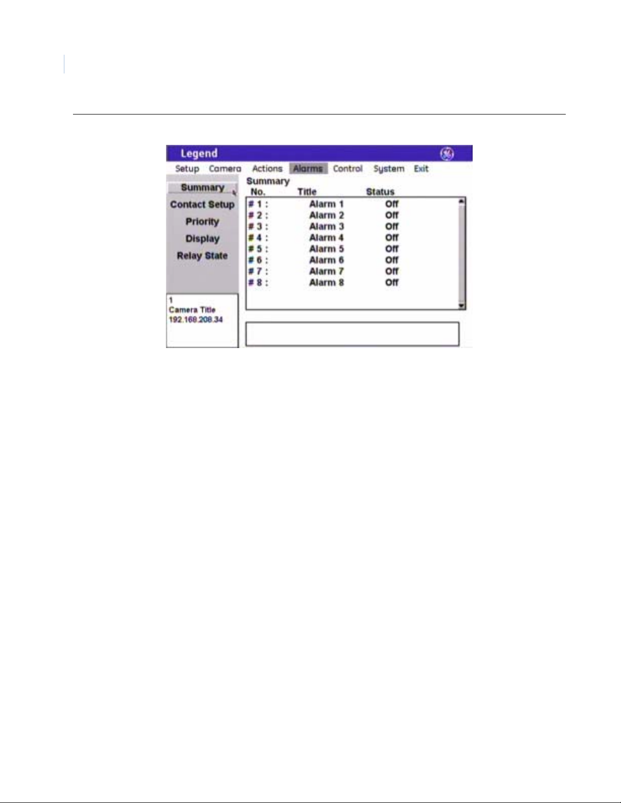
Legend
48
User Manual
Figure 41. Summary screen ( Alarms | Summary )
Summary:
No.
Summary:
Title
Summary:
Status
The No. column of the summary page lists all alarms in numerical order,
whether programmed or not. The eight alarms are numbered from 1 to 8.
The Title column of the summary page lists the titles for all available alarms,
whether programmed or not.
The Status column of the summary page lists the status of each programmed
alarm as either on (active) or off (inactive).
Page 53

Contact Setup screen ( Alarms | Contact Setup )
The Contact Setup screen is where you define the individual alarms. For tips, see Programming tips for dome
alarms on page 46.
Figure 42. Contact Setup screen ( Alarms | Contact Setup )
49
Note: Remember to select OK to save any changes you make on the page.
Contact no. The Contact no. drop-down box allows you to select the alarm number that
you want to program.
Contact type Alarm contacts are identified as N/O (normally open) or N/C (normally closed).
Default is N/O.
Contact name The Contact name box allows you to give your alarms unique titles. Default
numerical titles are provided. There is a 60-character limit for all titles, but be
aware of how much video you want to cover with your titles.
Action The Action feature associates an action with an alarm. An action is not required.
Choices are None (default), Preset, Tour, and Macro. If you select preset, tour,
or macro, the Action number feature is activated to let you select a specific one.
Action number The Action number feature lets you select a specific preset, tour, or macro, if
you selected preset, tour, or macro in the Action feature.
Relay 1 Each Relay feature associates one relay action with an alarm. Relays can be
used to trip such devices as speakers, doors, and DVMRs. Each alarm can be
programmed with up to three actions (one dome action and two relay actions).
You can set both relays to activate with an alarm. An action is not required.
Choices are No action (default), On, and Off.
Duration The Duration feature defines how long the relay is active.
Choices are Infinite (default) and seconds (1, 2, 3, 5, 15, 30, and 60). The
Infinite duration does not end unless another alarm is tripped.
Page 54

Legend
50
User Manual
Relay 2 Each Relay feature associates one relay action with an alarm. Relays can be
used to trip such devices as speakers, doors, and DVMRs. Each alarm can be
programmed with up to three actions (one dome action and two relay actions).
You can set both relays to activate with an alarm. An action is not required.
Choices are No action (default), On, and Off.
Duration The Duration feature defines how long the relay is active.
Choices are Infinite (default) and seconds (1, 2, 3, 5, 15, 30, and 60). The
Infinite duration does not end unless another alarm is tripped.
Priority screen (Alarms | Priority )
You can assign a priority ranking to your alarms that is independent of their contact numbers. The topmost
alarm in the priority list is the highest priority regardless of the alarm’s number, while the bottommost alarm is
the lowest priority . If more than one alarm is activated sequentially, only the highest priority alarm is actioned.
If several alarms are activated at the same time, then the one with the highest priority is actioned. After that
alarm has cleared, the next highest priority alarm will be actioned only if it is still active (for instance, a door is
still open). Alarms are not held in a queue.
Figure 43. Priority screen ( Alarms | Priority )
Note: Remember to select OK to save any changes you make on the page.
Reset The Reset button reorders the alarms in numerical order.
Raise priority The Raise priority button moves a selected alarm up in the priority list. Select
an alarm, then select Raise priority to move it up in the list.
Lower priority The Lower priority button moves a selected alarm down in the priority list. Select
an alarm, then select Lower priority to move it down in the list.
Page 55

Display screen ( Alarms | Display )
The Display screen is where you define the appearance of the block of alarms and relays that displays on the
monitor screen. To display the alarm block at all times, you must set the Alarm box content to All status and
the Alarm box duration to Indefinite.
Figure 44. Display screen ( Alarms | Display )
51
Note: Remember to select OK to save any changes you make on the page.
Alarm title This feature does not title the individual alarms. Alarms appear in a list (or
block) on the monitor screen according to the display settings you set. You
can give this alarm block a title with this feature to identify the group of
alarms displayed. There is a 60-character limit, but be aware of how much
video you want to cover with your alarm block.
Title POS The alarm block will appear on screen in a default position on the monitor
screen (upper right), but you can reposition it with the Title POS button. Be
aware of where you already have other titles (camera, privacy masks, presets,
tours, macros, and areas) positioned.
To set the position of the macro title:
1. Select Title POS.
2. Move the joystick to move the title to the desired position.
3. Press the iris + or the set ( ) key on the keypad to accept (save)
the new position or press the iris - or esc key to cancel (abort) the new
position.
Title font color Alarm titles will appear on screen in the color selected.
Choices are as shown. Default is Red.
Title font size Alarm titles will appear on screen in the font size selected.
Choices are as shown. Default is 12 pt.
Page 56

Legend
52
User Manual
Title font weight Alarm titles will appear on screen in the font weight selected.
Choices are as shown. Default is Bold.
Note: If All status is selected for the Alarm box content feature, then the select ed
Titlefont weight is overridden and all alarms are listed in the alarm box with
normal weight and only the active alarms are listed with bold weight.
Block color You can create a block (background) that offsets the alarm block from the
video behind it. The blocks will appear on screen in the color selected.
Choices are as shown. Default is White.
Block transparency You can set the block (background) to be a solid color or a transparency. The
blocks will appear on screen in the transparency selected.
Choices are as shown. Default is Solid.
Alarm box content The Alarm box content feature sets how many alarms will display on the
monitor screen in the alarm block.
Choices are Off (displays no alarms, whether active or inactive), All status
(displays all alarms, whether active or inactive), Highest priority (displays
only the highest priority alarm, when active), and Active only (displays all
active alarms). Active alarms appear as bold in the list when All status is
selected. Default is All status.
Alarm box duration The Alarm box duration feature sets how long the alarm block will display on
the monitor screen, when All status is selected for the Alarm box content
feature.
Choices are During action (default) and Indefinite (always displayed).
Horizontal alignment For future use.
Vertical alignment For future use.
Page 57

Relay State screen ( Alarms |Relay State )
Figure 45. Relay State screen ( Alarms | Relay State )
53
Note: Remember to select OK to save any changes you make on the page.
Summary:
Name
Summary:
State
The Name column of the summary page lists both relays in numerical order,
whether programmed or not. The two relays are numbered 1 and 2.
The State column of the summary page lists the status of each programmed
relay as either on (active) or off (inactive).
Relay 1 on The Relay 1 on button lets you turn relay 1 on regardless of the current state
of any associated alarm.
Note: If you select Relay 1 on and select OK, then you are programming the dome to
activate this relay each time the dome is powered up.
Relay 1 off The Relay 1 off button lets you turn relay 1 off regardless of the current state
of any associated alarm.
Relay 2 on The Relay 2 on button lets you turn relay 2 on regardless of the current state
of any associated alarm.
Note: If you select Relay 2 on and select OK, then you are programming the dome to
activate this relay each time the dome is powered up.
Relay 2 off The Relay 2 off button lets you turn relay 2 off regardless of the current state
of any associated alarm.
Show relay state (check box) The Show relay state feature, when checked, lets you display the status of the
relays on the monitor screen at all times. If the status of alarms is also being
displayed, the relays will be listed at the bottom of the list after the alarms.
Page 58

Legend
54
User Manual
Control menu
You can program a variety of general camera features that control each dome. These general features include a
specific operation for the camera to execute when it is first powered up (Power-on), a specific operation for the
camera to execute when the keypad has been inactive for a duration of time (Resume), and speed settings for
panning, tilting, autopanning, and moving between presets.
Figure 46. Control menu
Command Map screen ( Control | Command Map )
The dome provides the ability to remap any preset or tour command coming in from a keypad to activate any of
the 127 presets, 16 tours, or 32 macro actions. This enables you to manually initiate any of the expanded
capabilities of the dome from keypad controllers with limited command capability. The command mapping
does not effect any of the internal command operations the dome performs, such as resume and alarm actions.
It only effects the actions the dome will perform when it receives a command from an external device (keypad
or alarm interface). An example of remapping is using a preset command from the keypad to run Macro 1. In
the command map programming, you would select the preset number y ou wish to use and remap that command
to activate Macro 1.
Note: Most keypads have a limited number of preset numbers they can call, whic h will limit how many commands can be
remapped. If you have a GE KTD-405 keypad with firmware version 1.2.09 or later, then you can call up all 127 preset
numbers (1 through 127) directly from the keypad. If, however, you have a GE KTD-405 keypad with an earlier version of
firmware, then you can use the keypad to call up only the first 63 preset numbers (1 through 63). If you are using
presets 62 and 63 for your left and right autopan limits, then you have a total of 125 or 61 preset numbers that you can
call up from the keypad. To verify your keypad’s versio n, press and hold the mon key on the keypad, until the keypad
beeps, then press the >> key.
To create your presets, if you have not already done so, see Presets screen ( Actions | Presets ) on page 29.
To create your tours, if you have not already done so, see ShadowTours screen ( Actions | ShadowTours ) on
page 38.
To create your macros, if you have not already done so, see Macros screen ( Actions | Macros ) on page 40.
Page 59

Figure 47. Command Map screen ( Control | Command Map )
55
Note: Remember to select OK to save any changes you make on the page.
Summary The Summary feature lists what actions are currently assigned to each
command. The Summary feature lists presets and tours separately, according
to whichever list (preset or tour) you currently have selected under the
Command option.
Command The Command feature changes the group of commands listed in the summary
between presets and tours.
Auxiliary input (command) The Auxiliary input feature specifies the number of the command (for
example, Preset 2 or Preset 102) that is to be remapped.
Note: To see the title of the selected command, go to the corresponding summary or
list under the Actions menu .
Assigned action The Assigned action feature remaps the selected command (preset or tour) to
the same type of command or to another type of command (for example, from
a preset to a tour or macro).
Auxiliary input (assigned action) The Auxiliary input feature specifies the number of the command that is
assigned.
Note: To see the title of the selected command, go to the corresponding summary or
list under the Actions menu .
Update The Update feature, when selected, remaps the selected command with the
selected action.
Restored default The Restore default feature, when selected, unmaps all commands in the
current list (preset or tour). Any commands remapped in the other list (tour or
preset) are not restored.
Page 60

Legend
56
User Manual
Power-on and Resume screen (Control | Power-on and Resume)
Figure 48. Power-on and Resume screen ( Control | Power-on and Resume )
Note: Remember to select OK to save any changes you make on the page.
Power-on operation Power-on defines the first operation that the dome performs after it is
powered up and initialized.
Choices are Off (default), Preset, Macro, ShadowTour, and Autopan.
Number
(power-on operation)
Enter a number for the operation selected under Power-on operation.
Choices are based on the selection made under operation.
Resume delay Resume delay is a feature that sets how long the keypad is inactive before the
Resume operation is performed.
Choices are Off (default), 15 sec, 30 sec, 1 min, 2 min, 3 min, 4 min, and 5 min.
Resume operation Resume defines the operation for the dome to perform after the keypad has
been inactive for a period of time. This command will not activate if a tour or
autopan is in progress.
Note: If turned on, the Resume feature interrupts tours an d autopa nnin g. Resu me does
not interrupt alarms.
Choices are available only if a delay time is selected and include Preset
(default), Macro, ShadowTour, and Autopan.
Number
(resume operation)
Enter a number for the operation selected under Resume operation.
Choices are based on the selection made under operation.
Page 61

Speeds/Tracking screen (Control | Speeds/Tracking )
Figure 49. Speeds/Tracking screen ( Control | Speeds/Tracking )
57
Note: Remember to select OK to save any changes you make on the page.
Manual PTZ:
Max pan speed (deg/s)
The Max pan speed is a feature that sets the fastest the camera will move (in
degrees per second) while manually panning.
Choices are 100 through 250 (default) in increments of 10.
Manual PTZ:
Max tilt speed (deg/s)
The Max tilt speed is a feature that sets the fastest the camera will move (in
degrees per second) while manually tilting.
Choices are 100 through 250 (default) in increments of 10.
Macro/autopan speed:
Fast (deg/s)
The Fast speed setting is a feature that sets how fast the camera moves (in
degrees per second) at the fast speed while traveling between presets in
macros and while autopanning.
Choices are 0 through 20 in increments of 2. Default is 16. A setting of 0
(degrees/second) makes the camera move as slowly as possible. This is not a
stop motion command.
Macro/autopan speed:
Medium (deg/s)
The Medium speed setting is a feature that sets how fast the camera moves (in
degrees per second) at the medium speed while traveling between presets in
macros and while autopanning.
Choices are 0 through 20 in increments of 2. Default is 10. A setting of 0
(degrees/second) makes the camera move as slowly as possible. This is not a
stop motion command.
Macro/autopan speed:
Slow (deg/s)
The Slow speed setting is a feature that sets how fast the camera moves (in
degrees per second) at the slow speed while traveling between presets in
macros and while autopanning.
Choices are 0 through 20 in increments of 2. Default is 4. A setting of 0
(degrees/second) makes the camera move as slowly as possible. This is not a
stop motion command.
Page 62

Legend
58
User Manual
Autopan speed The Autopan speed is a feature that sets how fast the camera moves while
autopanning.
Choices are Slow (default), Medium, and Fast. These settings are scaled
according to the settings set for the slow, medium, and fast Macro and
autopan speed settings. If the numbers in the Macro and autopan speed
setting boxes are lower, then the corresponding Autopan speed settings
will be slower. For example, if the fast M acro and autopan speed setting
were set to 1, instead of 16, then the fast Autopan speed setting would operate
proportionately slower.
Enable proportional zoom
operation
Proportional zoom is a feature that slows the pan and tilt speeds as you zoom
in. This makes it easier to follow far off moving tar gets when you are zoomed
in to them.
Choices are checked (default) and unchecked.
Enable zoom variable tilt Zoom variable tilt is a feature that lowers the upper tilt limit when the camera is
zoomed out to a wide angle of view so that the trim ring of the dome is not in
view . The feature raises the upper tilt limit when the camera zooms in to a
narrower angle of view, because the trim ring recedes out of view.
Choices are checked (default) and unchecked.
Enable electronic image flip
(E-flip)
Electronic image flip (E-flip) is a feature that electronically flips the video
image when the camera is looking straight down so that the camera does not
have to physically flip.
Choices are checked (default) and unchecked.
Page 63

System menu
You can access diagnostics, status, and communication logs of your system’s features through the System menu
screens. Under Diagnostics, you can see what temperature your dome is operating at. Under Status, you can see
a detailed listing of your dome’s site (camera) information such as title and IP address, customized settings,
alarm status, and customized presets, tours, masks, and macros. Under Logs, you can see a history of the
command, protocol, and motor messages being managed by the dome. Under Firmware Update, you can
update the dome’s software (firmware), if you are logged on as the Installer.
Figure 50. System menu
59
Page 64

Legend
60
User Manual
Diagnostics screen ( System | Diagnostics )
The Diagnostics screen provides the operating temperature of your dome.
Figure 51. Diagnostics screen ( System | Diagnostics )
Status screen ( System | Status )
The Status screen provides a detailed listing of your dome’s site (camera) information such as title and IP
address, customized settings, alarm status, and customized presets, tours, masks, and macros.
Figure 52. Status screen ( System | Status )
Page 65

Logs screen (System|Log)
The Logs screen provides a history of the command, protocol, and motor messages of the dome’s most recent
operations. Level 1 logs list the most restrictive and important messages, level 2 list those of medium restriction
and importance, and level 3 lists those of least restriction and importance.
Figure 53. Log screen (System | Log )
61
Firmware Update screen ( System | Firmware Update )
There are two ways to reload or update the software in your dome. One way is using the Firmware Update
feature. The other way is using a web browser . The Firmware Update feature is explained here. To use the web
browser method, see Reloading or updating the software on page 65.
The Firmware Update screen allows you to reload or update the dome’s software (firmware) easily through the
Ethernet connection.
Page 66

Legend
62
User Manual
Figure 54. Firmware Update screen ( System | Firmware Update )
T o update (or reload) the dome’s software using the Firmware Update feature, see Figure 54 and do the following:
CAUTION
CAUTION
For all installations, heed these cautions:
• DO NOT interrupt the reload/update purpose until it has completed. Don’t use the keypad, don’t
break the network connection, and don’t cycle the power to the dome.
• When flashing soft ware up grades to the dome over a standar d IP network via the do me's Ethernet
connection, ensure that the network is secured from unauthorized access. Like all Ethernet
connections, the dome's Ethernet con nection has no security against unauthori zed access. You
may consider connecting the Ethernet cable only when you are flashing the dome, unless you
have the dome connected to a secure, isolated network.
1. Create your TFTP server using the corresponding file from the Legend system CD.
Note: Make sure that the TFTP server is in the same physical IP and subnet network as the dome. We do not
recommend to update the dome through a gateway. The extended setup that is required is not provided.
2. Copy the update file from the Legend system CD to the TFTP server.
3. Confirm or retype the TFTP server’s IP address into the TFTP host address box.
4. Confirm or retype the file name into the File name box.
5. Select Begin update.
6. At this point, ensure that the reload/update process is not interrupted. The system is not safe to interact
with until after the system is successfully rebooted. Wait until after you see the splash and color bar
screens on the monitor screen, and live video is again playing normally.
You may see a blank or gray screen for up to five minutes. Do nothing until you see live video again.
Only after 10 minutes have elapsed without a successful reload/update should you try cycling
power to restart the dome.
Page 67

System operation
-fli
Legend domes are controlled from at least one controller keypad. Refer to your keypad’s manual for
instructions on operating the dome. This chapter lists some general guidelines and restrictions for operating the
Legend domes.
Setting autopan limits
63
When setting autopan limits, be aware that you must
set both the right and left limit in the same tilt
hemisphere. You can set them in either tilt
hemisphere, but you cannot cross tilt hemispheres,
meaning that you cannot pass the bottommost point
Figure 55. No E-flip with autopan limits
Legend
0°
(+90°)
Legend
180°
(-90°)
or turn the camera upside down. Allowing the
camera to E-flip will create an invalid set of autopan
limits that may cause unexpected camera
performance. See Speeds/Tracking screen
Positive (+)
hemisphere
Negative (-)
hemisphere
( Control | Speeds/Tracking ) on page 57.
Remember that there is a positive and a negative
hemisphere. Depending on what coordinates you
selected under Setup | Preferences | Coordinates, the
positive hemisphere will be identified by a tilt
90°
(0°)
No E-flip allowed
with autopan limits
position of 0° to 90° or +90° to 0°.
Rebooting the dome
If you are using a GE KTD-405 keypad, and have valid communicati on between the keypad and the dome, y ou
can easily reboot a dome when necessary. You cannot currently reboot Legend domes from other keypads.
To reboot a dome, do the following from the KTD-405 keypad:
1. At the normal display (CAMERA #/MONITOR #), press and hold the set ( ) key on the keypad
until you hear a beep and the programming code display appears on the keypad’s LCD.
2. At the ENTER PROGRAMMING CODE: display, enter the reset access code by pressing the 1, 4, 7,
6, and seq keys.
3. At the RESET TO DEFAULTS? display, press iris + for yes.
4. At the reset which display, press 3 to select CAMERA.
5. At the RESET CAMERA #? ARE YOU SURE? display, press iris + to select yes.
The camera reboots in about 60 seconds. You will see the RESETTING CAMERA # display on the
keypad LCD and the splash screen and color bars on the monitor screen as the camera reinitializes itself.
Resetting the dome
You can reset the dome whether or not you have valid communication between the keypad and the dome.
To reset the dome, cycle the power to the dome by turning the power off then on.
Page 68

Legend
64
User Manual
Calling up presets from a keypad
Most keypads have a limited number of preset numbers they can call. If you have a GE KTD-405 keypad with
firmware version 1.2.09 or later, then you can cal l up all 127 preset numbers (1 through 127) directly from the
keypad. If, however, you have a GE KTD-405 keypad with an earlier version of firmware, then you can use the
keypad to call up only the first 63 preset numbers (1 through 63 ). If you are using presets 62 and 63 for your
left and right autopan limits, then you have a total of 125 or 61 preset numbers that you can call up from the
keypad.
To verify your keypad’s version, press and hold the mon key on the keypad, until the keypad beeps, then press
the >> key.
To create presets, see Presets screen ( Actions | Presets ) on page 29.
To create tours, see ShadowTours screen ( Actions | ShadowTours ) on page 38.
To create macros, see Macros screen ( Actions | Macros ) on page 40.
To remap presets, tours, and macros, see Command Map screen ( Control | Command Map ) on page 54.
To use the KTD-405 keypad, see KTD-405 Controller Keypad User Manual (1036547).
Interrelationship between the Exposure and Day/Night features
The Day/Night feature works only if the Exposure feature is set to Auto or Return to auto. Two conditions can
prevent the camera from switching between the color and monochrome modes according the Day/Night
setting. One, if you’ve overridden the Auto Exposure setting with manual commands from the keyp ad. Two, if
you’ve called a preset (or a command containing a preset) that is programmed to override the Auto Exposure
setting.
In the second scenario, the camera returns to the Auto Exposure setting after you leave the preset. In the first
scenario, you must issue a command to return to the Auto Exposure setting. Using the iris key on the keypad
manually adjusts the camera’s iris setting or shutter speed, overriding the Auto Exposure setting. You must
issue a pan or tilt command from the keypad to leave the manual override and return to the Auto Exposure
setting. While you remain in the manual override, the color and monochrome modes of the Day/Night setting
will not switch according to the changes in the lighting conditions.
Page 69

Troubleshooting, maintenance, support
This section provides information to help you diagnose and solve various problems that may arise while
configuring or using your GE Security product and offers technical support contacts in case you need
assistance. See Contacting technical support on page 67.
Troubleshooting your Legend system
Common programming issues
Is the programming interface not responding?
• First, reboot the camera with the keypad using the procedure in Rebooting the dome on page 63.
• If that doesn’t work, then reset (cycle) the power to the dome by turning the power off then on.
Forget your passcode?
If you forget the passcodes for a dome, you will need to send the dome back to the factory so that it can be reset
by the factory with no passcodes.
65
Is the programming interface not opening?
Contact technical support. See Contacting technical support on page 67 for web, e-mail, fax, and phone
information.
Is the programming interface not closing?
Reset (cycle) the power to the dome by turning the power off then on.
Maintenance
Reloading or updating the software
There are two ways to reload or update the software in your dome. One way is using the Firmware Update
feature from the programming interface. The other way is using a web browser. The web browser method is
explained here. To use the Firmware Update feature, see Firmware Update screen ( System | Firmware
Update ) on page 61.
To reload or update software using the http method:
CAUTION
CAUTION
For all installations, heed these cautions:
• DO NOT interrupt the reload/update purpose until it has completed. Don’t use the keypad, don’t
break the network connection, and don’t cycle the power to the dome.
• When flashing soft ware up grades to the dome over a standar d IP network via the do me's Ethernet
connection, ensure that the network is secured from unauthorized access. Like all Ethernet
connections, the dome's Ethernet con nection has no security against unauthori zed access. You
may consider connecting the Ethernet cable only when you are flashing the dome, unless you
have the dome connected to a secure, isolated network.
1. Make sure that the computer that you are using for the server has the same subnet address as the dome.
The default addresses are:
Page 70

66
Legend
User Manual
• IP for domes: 192.168.208.XXX, where XXX is the site number (or camera address) of the
dome.
• Subnet mask for domes: 255.255.255.0
2. Copy the update file from the Legend system CD to your computer. It will usually be named in the
format of Legend.raw.gz with some variations.
3. Open Microsoft Internet Explorer.
4. Type your dome’s IP address into the address box in the form of
http://XXX.XXX.XXX.XXX/update.htm.
5. Press Enter or click Go.
6. If this is the first time you are accessing the
web browser for the dome after it has rebooted,
Figure 56. Legend web-based log in screen
you will be asked to log on to the dome.
• Only installers have passcode
permission to update software.
• You need to type in Installer with a
capital letter I.
• Finally , you need to use the same
passcode as is used for accessing the
dome’s programming interface. Leave
the password box blank, if the Installer
passcode was not turned on for the
programming interface.
7. At the Legend web based firmware update
page, enter the name of the firmware file, if
Figure 57. Legend web based firmware update page
known, or click the Browse button to locate
the file.
8. If you are browsing for the file, once you
find it, click File | Open to populate the
filename entry on the previous page.
9. Click Send File.
10. At this point, ensure that the reload/update process is not interrupted. The unit is not safe to interact
with until after the system is successfully rebooted. Wait until after you see the splash and color bar
screens on the monitor screen, and live video is again showing normally.
You may see a blank or gray screen for up to five minutes. Do nothing until you see live video again.
Only after 10 minutes have elapsed without a successful reload/update can you try cycling power to
restart the dome.
Page 71

After you have clicked Send File, the reload/update can continue processing in one of two ways:
• In most cases, a notice will appear on the monitor screen saying that the update is in progress,
while another message appears on the computer screen in Internet Explorer saying that the
update is proceeding successfully.
• In some cases, the camera may not have enough memory to process the reload/update files. In
which case, a camera memory low message is displayed. If you get this message, the camera
will automatically reset (reboot) itself and when it is again displaying live video, you will need
to go back to the address box in Internet Explorer and reselect the dome’s IP address with the
correct file extension, which should now appear beside the IP address. The reload/update
should process normally after selecting the update file this second time.
Contacting technical support
For assistance installing, operating, maintaining, and troubleshooting this product, refer to this document and
any other documentation provided. If you still have questions, you may contact technical support during
normal business hours (Monday through Friday, excluding holidays, between 6 a.m. and 5 p.m. Pacific Time).
Sales Technical support
67
Phone:
E-mail
Fax
Note: Be ready at the equipment before calling for technical support.
Toll-free: 888.GESECURity (888.437.3287 in the US, i ncluding Alaska and Hawaii; Puerto Rico; Canada).
Outside the toll-free area: 503.885.5700.
info@gesecurity.com generaltech@ge.com
800.483.2495 541.752.9096 (available 24 hours a day)
Online publication library
Another great resource for assistance with your GE Security products is our online publication library,
available to all of our customers on our website. To access our publication library, go to our website at the
following location:
http://www.gesecurity.com
In the Tools area at the top, click the Publication Library link then select V ideo Surveillance. After you register
and log on, you may search through our online library for the documentation you need.
1
1. Many GE Security documents are provided as PDFs (portable document format). To read these documents, you will need
Adobe Acrobat Reader, which can be downloaded free from Adobe’s website at www.adobe.com.
Page 72

Legend
68
User Manual
Appendix. System defaults
Default title positions
Figure 58 shows you all of the titles that you can turn on to appear on the monitor screen.
Figure 58. Default title positions
Default programming settings
Table 4 lists the system’s programming defaults.
Table 4. Default programming settings
Setting Default
Alarm box content All stat us
Alarm box duration During action
Alarm contact type N/O
Autopan speed Slow
Autoslow shutter Off
Backlight compensation Off
Block color Black
Block transparency No color
Branding Off
Contact type (alarms) N/O
Page 73

Table 4. Default programming settings
Setting Default
Day/Night Automatic
Digital zoom limit 12x
Electronic image flip (E-flip) On
Exposure control Iris
Gain 0
Language English
Lift 0
Night mode Off
IP address 192.168.208.250
Pan coordinates Degrees 360
Pan limits Off
69
Passcodes Off (blank)
Phase adjustment 50°
Phase lock enabled Off
Power-on Off
Preset title duration Infinite
Privacy mask color Gray
Relay 1/Relay 2 No action
Relay duration Infinite
Resume Off
Resume delay Off
Resume operation Preset
Return-to-auto On
Subnet mask 255.255.255.0
Temperature display Off
Temperature display duration During action
Temperature thresholds
0
(high and low)
Tilt coordinates Degrees 180
Tilt limits Off
Title font color White
Page 74

Legend
70
User Manual
Table 4. Default programming settings
Setting Default
Title font weight Bold
Title font size 26 pt
T itle length 60 characters
White balance Auto
Zoom coordinates Power
Zoom proportional On
Zoom speed Variable
Zoom variable tilt On
Page 75

Index
71
A
action.......................................................................................................46
actions menu ........................... ... ............................................ ... ..............29
admin passcode.......................................................................................12
advanced programming...........................................................................10
alarms......................................................................................................46
acknowledge.......................................................................................46
action..................................................................................................46
clear....................................................................................................46
priority......... .................................................................................46, 50
tips ......................................................................................................46
alarms menu............................................................................................46
areas
program..............................................................................................45
areas screen.............................................................................................43
autopan.................................... ... ... ............................................ ........57, 58
autopan limits..........................................................................................63
B
backlight compensation ....................................................................19, 35
basic programming ...................................................................................7
C
duration
alarm box............................................................................................52
high temperature................................................................................16
low temperature..................................................................................16
macro..................................................................................................41
preset title...........................................................................................31
relay..............................................................................................49, 50
E
E-flip.......................................................................................................58
electronic image flip (E-flip) ........... .... ... ... ............................................ .58
exposure............................................................................................37, 64
auto.........................................................................................24, 37, 64
autoslow shutter .................................................................................24
control ................................................................................................24
iris.................................................................................................24, 37
lowest shutter speed ...........................................................................24
manual..........................................................................................24, 37
return to auto......................................................................................24
settings................................................................................................23
shutter...........................................................................................24, 37
F
firmware update screen.................................................................... ... ... .61
camera menu...........................................................................................19
canceling...................................................................................................5
command map screen....... ............................................ ...........................54
contact setup screen ................................................................................49
control menu ....................... .... ... ............................................ ... ... ...........54
conventions ...............................................................................................1
coordinates
pan......................................................................................................17
tilt........................................................................................................17
zoom....................................................................................................17
D
day/night .......... ............................................. ....................................22, 64
defaults
programming settings.........................................................................68
system .................................................................................................68
title positions ......................................................................................68
diagnostics screen ................... ... ............................................ ... ..............60
digital zoom ............... ............................................ ... ..............................27
due north .......................... ............................................ ...........................18
G
gain..........................................................................................................27
I
installer passcode.... ... ............................................. ... ............................. 12
interface behavior .....................................................................................5
isolated network........................................................................................2
J
joystick
as simulated mouse...............................................................................5
as video controller................................................................................5
K
keyboard....................................................................................................6
keypad
limitations...........................................................................................64
shortcuts ...............................................................................................6
Page 76

Legend
72
DRAFT User Manual
L
lift............................................................................................................27
logs screen...............................................................................................61
M
MAC address ................. ... ... ............................................ ... ....................15
macros.....................................................................................................40
macros screen..........................................................................................40
maintenance ............................................................................................65
masks
area.....................................................................................................43
privacy................................................................................................19
memory screen........................................................................................10
N
network screen ........................................................................................14
night mode ..............................................................................................35
north point...............................................................................................18
O
operation .................................................................................................63
operator passcode....................................................................................12
P
program
areas...................................................................................................45
presets........................ ... ... ...........................................................7, 8, 32
privacy masks.....................................................................................21
ShadowTours..................................................................................9, 39
tours................................................................................................9, 39
programming
advanced.............................................................................................10
basic .....................................................................................................7
programming interface......................................... .....................................3
accessing ..............................................................................................3
navigating.............................................................................................5
proportional zoom...................................................................................58
publication library...................................................................................67
R
reboot ......................................................................................................63
references..................................................................................................1
relay ............................................................................................46, 49, 50
relay state screen.................................. ... ... .............................................53
reloading the software.... ... ... ... ............................................. ... ................65
remapping
presets.................................................................................................54
tours....................................................................................................54
reset.........................................................................................................63
resume.....................................................................................................56
return to auto............................... ... ............................................ ... ..........24
pan.............................................................................................. .......17, 57
pan limits.................... ............................................. ................................28
passcode screen.......................................................................................11
passcodes ................................................................................................11
admin..................................................................................................12
installer...............................................................................................12
operator..............................................................................................12
phase lock ............................................... ... ............................................ .26
power-on.................................................................................................56
power-on and resume screen......... .... ... ... ............................................ ... .56
preferences screen...................................................................................15
presets ........................................................... ... ...................................7 , 29
program......................................................................................7, 8, 32
remapping...........................................................................................54
presets screen..........................................................................................29
priority screen .........................................................................................50
privacy masks ............................... .... ......................................................19
program..............................................................................................21
privacy masks screen ................. ... ............................................. .............19
product
overview................................................................................................2
S
safety cautions...................................................................2, 11, 14, 27, 62
safety terms and symbols........................................................................ ..1
saving........................................................................................................5
selecting ....................................................................................................5
settings screen...................... ... ............................................. ... ................22
setup menu..................................................... .........................................10
ShadowTours
program..........................................................................................9, 39
ShadowTours screen............ ... ............................................. ... ................38
shortcuts....................................................................................................6
show relay state................. ............................................ .... ......................53
site-tied memory ............................ ... ............................................ ..........10
software
updating or reloading.........................................................................65
speed
autopan.........................................................................................57, 58
pan......................................................................................................57
tilt .......................................................................................................57
speeds/tracking screen ............................................................................57
stabilization.............................................................................................26
status screen............................................................................................60
system defaults........................................................................................68
Page 77

73
system menu ...........................................................................................59
system operation .....................................................................................63
T
technical support.....................................................................................67
tilt............................................................... ... ... .................................17, 57
tilt limits............................................................................................27, 28
timeout ......................................................................................................5
time/date screen ......................................................................................13
tips for alarms ............ ............................................ .................................46
title positioning .................................................................................33, 38
tours
program.............. ............................................ ................................9, 39
remapping...........................................................................................54
troubleshooting .......................................................................................65
U
updating the software.................................... ... ... ....................................65
W
white balance ....................................................................................23, 36
Z
zoom............................................................................................17, 27, 58
variable tilt.........................................................................................58
 Loading...