

Page 1
INSTALLATION INSTRUCTIONS FOR YOUR NEW
•
STOP!
TOOL LIST
• 1/8" drill bit
• Electric or hand drill
• No. 1 or No. 2 Phillips
screwdriver
• Pencil
• Ruler and straightedge
• Hand or saber saw
• Pipe wrench
• Adjustable wrench
• 3/16" hex socket
driver
• 12" spirit level
ADDITIONAL MATERIAL YOU MAY NEED:
• Gas line shut-off valve
• Pipe joint sealant
• 1/2" pipe nipple
For flexible connection where local codes
permit:
• Coated and approved flexible metal tubing (same
3/4" or 1/2" I.D. as gas supply line)
• Adaptor or connector
For rigid connection:
• Pipe fittings or union as required
229C
4053P085
Pub. No. 31-10253
IMPORTANT:
Remove all packing material
and literature from the cooktop before
connecting gas and electrical supplies.
STOP!
30" SEALED GAS COOKTOPS
Before you begin: Read these instructions completely and carefully.
IMPORTANT: Save these instructions for local inspector's use.
IMPORTANT: OBSERVE ALL GOVERNING CODES AND ORDINANCES.
INSTALLER: Be sure to leave these instructions with the Consumer.
CONSUMER: Keep these instructions with your Use and Care Book for future
reference.
This appliance must be properly grounded.
Installation of this cooktop must conform with local
FOR YOUR SAFETY
WARNING!! If the information in
this manual is not followed
exactly, a fire, explosion, or gas
leak may result causing property
damage, personal injury, or
death.
DO NOT STORE OR USE GASOLINE OR
OTHER FLAMMABLE VAPORS AND LIQUIDS
IN THE VICINITY OF THIS OR ANY OTHER
APPLIANCE!
WHAT TO DO IF YOU SMELL
GAS:
• Do not try to light any
appliance.
• Do not touch any electrical
switch; do not use any
phone in your building.
• Immediately call your gas supplier from a
neighbor’s phone. Follow the gas supplier’s
instructions.
• If you cannot reach your gas supplier, call
the fire department.
codes or in the absence of local codes with the
National Fuel Gas Code, ANSI Z223. 1-Latest edition.
• Be sure your cooktop is installed properly by a qualified
installer or service technician.
• To eliminate reaching over surface burners, cabinet
storage above burner should be avoided.
• Do not install the unit near an outside door or where a
draft may affect its use.
Installation and service must be performed by
a qualified installer, service agency or the gas
supplier.
This cooktop has been design certified by the American
Gas Association. You’ll find safety precautions in your
Use and Care book. Read them carefully.
1
Page 2
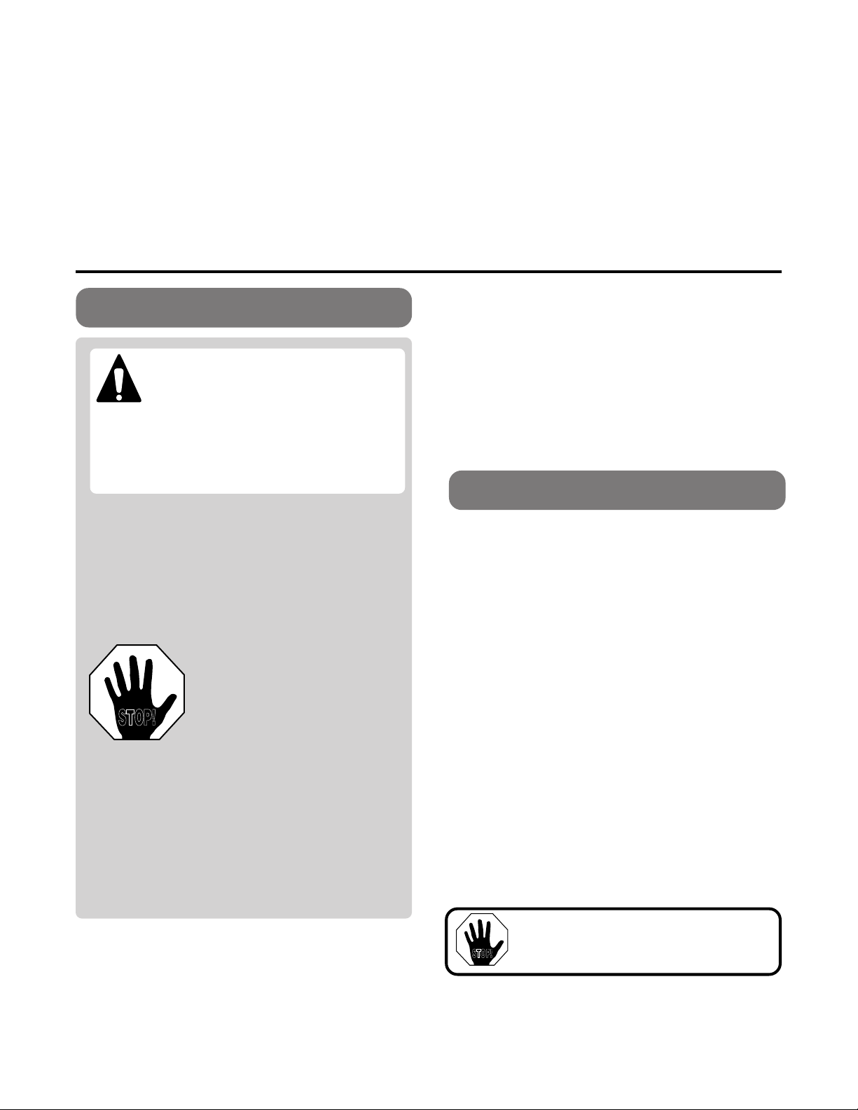
ELECTRICAL REQUIREMENTS
19 3/8"
28 3/8"
21"
30"
28 1/2"
3"
2 1/4"
MIN.
3 1/4" MIN.
19 5/8"
14 1/4"
COOKTOP
FROM CUTOUT
CENTER LINE
1" FROM BACKWALL
3 3/4" MIN.
CLEARANCE
TO SIDE WALL
30" MIN.
TO CABINET
3 3/4" MIN.
CLEARANCE
TO SIDE WALL
13"
MAX.
DEPTH
18" MIN.
TO CABINET
PROVIDE ADEQUATE
GAS SUPPLY
This cooktop is designed to operate on natural gas at 4"
of water column pressure. It is shipped from the factory
set for natural gas.
A convertible pressure regulator is connected in series
with the manifold of the cooktop and must remain in
series with the supply line regardless of whether natural
or L.P. gas is being used.
FOR PROPER OPERATION, THE MAXIMUM
INLET PRESSURE TO THE REGULATOR MUST
BE NO MORE THAN 14" OF WATER COLUMN
PRESSURE.
For checking the regulator, the inlet
pressure must be at least 1" (or 3.4 KPA) greater than
the regulator output setting. If the regulator is set for 4"
of water column pressure, the inlet pressure must be at
least 5". If the regulator is set for 10", the inlet pressure
must be at least 11".
The gas supply line to the cooktop should be 1/2" or
3/4" pipe.
This Appliance must be electrically grounded. Check
with your local codes which apply in your area. If no
local codes apply, the National Electrical Code, ANSI/
NFPA No. 70-Latest Edition must be followed. Write to:
National Fire Protection Association
Batterymarch Park
Quincy, MA 02269
Be sure the installation of this cooktop in a mobile home
conforms with the Manufactured Home Construction
and Safety Standard, Title 24 CFR, Part 3280. If this
standard does not apply, you must follow the standard
for Manufactured Home Installations, ANSI A225. 1 and
Manufactured Home Installations, Sites, and
Communities and ANSI/NFPA 501A or with local codes.
You can get a copy of the Federal Standard by Writing:
Office of Mobile Home Standards
HUD Building
451 7th Street, S.W.
Washington, D.C. 24010
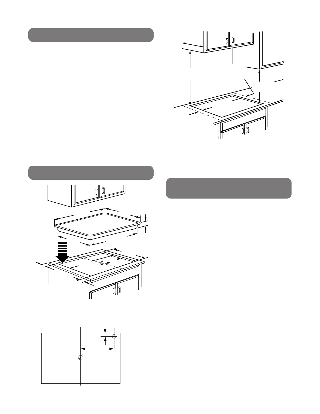
PREPARE THE OPENING
Fig. 3
• Make sure the wall coverings, countertop and
cabinets around the cooktop can withstand the heat
(up to 200°F) generated by the cooktop.
• Provide adequate clearances between cooktop and
adjacent combustible surfaces.
Fig. 1
Fig. 2
12 1/2"
2
Page 3
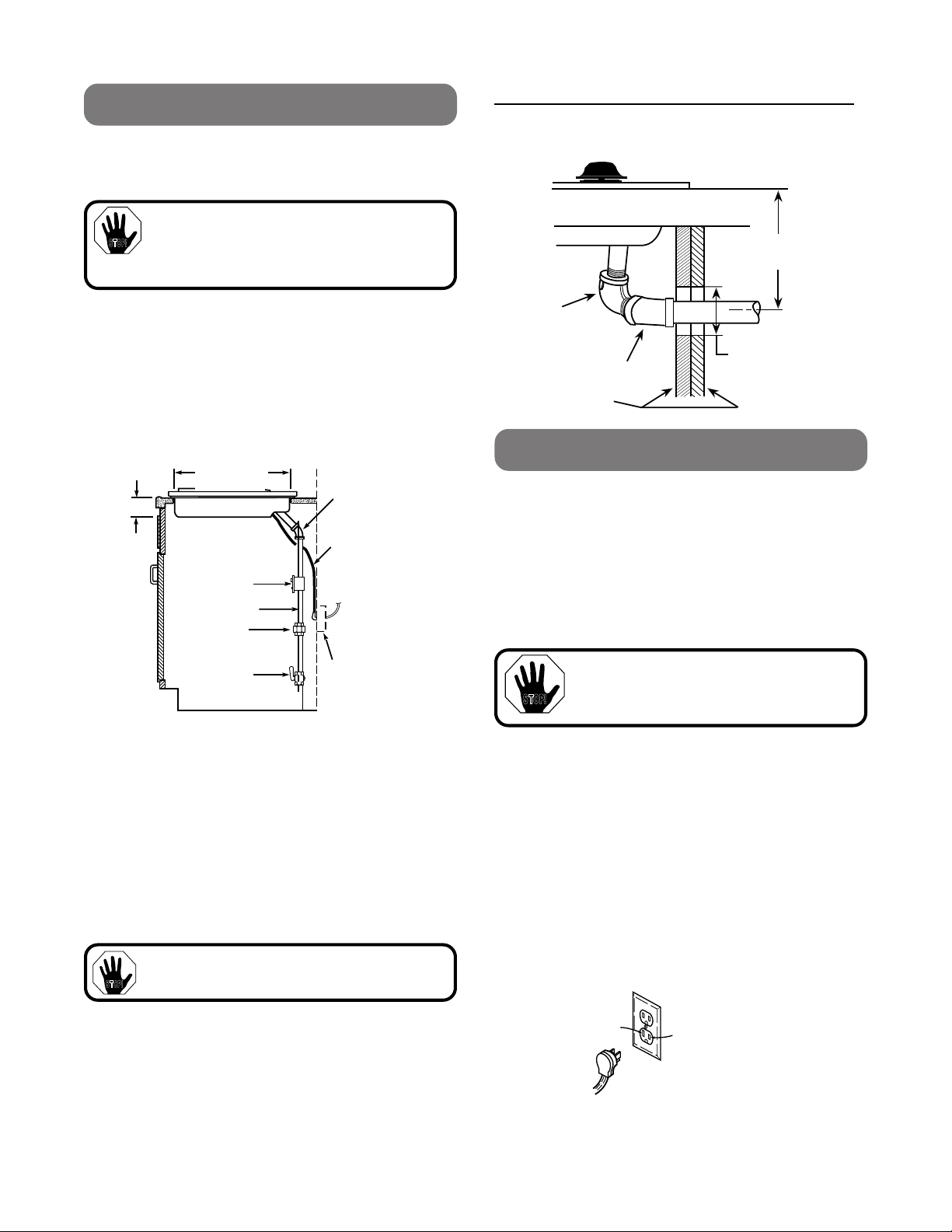
GAS CONNECTIONS
90°
STREET EL
45°
ELBOW
CABINET SIDES
2" DIA. HOLE (20 7/8"
FROM FRONT OF
COUNTERTOP TO
HOLE CENTER)
5" TO CENTER
OF 2" DIA. HOLE
FROM COUNTERTOP
ELECTRICAL CONNECTION
Because of potential safety hazards under certain
conditions we strongly recommend against the use of
an extension cord. However, if you still elect to use an
extension cord, it is absolutely necessary that it be a UL
listed 3-wire grounding type appliance extension cord
and that the current carrying rating of the cord in
amperes be equivalent to or greater than the branch
circuit rating. Such extension cords are obtainable
through your local appliance dealer.
IMPORTANT:
(Please read carefully) FOR
PERSONAL SAFETY, THIS APPLIANCE MUST
BE PROPERLY GROUNDED.
STOP!
Insure proper
ground and
firm connection
before use
L
N
STOP!
3" MIN.
19 1/2"
CUTOUT
45°
PRESSURE
REGULATOR
SHUT OFF
VALVE
1/2" PIPE
COUPLING
ELECTRICAL
CORD
34"LONG
ELECTRICAL
OUTLET
12" BELOW
COUNTERTOP
19 5/8"
CUTOUT
Fig. 4
5.
Check for leaks. After connecting cooktop to gas,
check system for leaks with a manometer. If a
manometer is not available, turn the gas supply on
to the cooktop and use a liquid leak detector at all
joints and connections to check for leaks.
Tighten all connections if necessary to prevent gas
leakage in the cooktop or supply line.
Check alignment of valves after connecting the cooktop
to the gas supply to be sure the manifold pipe has not
been moved. A misalignment could cause the valve
knob stem to rub on the control panel, resulting in a gas
leak at the valve.
DO NOT USE OPEN FLAME TO CHECK FOR
LEAKS!
STOP!
1.
Connect the cooktop to the gas supply line.
2. NEVER REUSE OLD CONNECTORS WHEN
INSTALLING THIS COOKTOP.
INSTALLATION OVER BUILT-IN OVEN
See built-in oven installation for complete installation
instruction.
3.
4.
Disconnect this cooktop and its individual
shutoff valve
during any pressure testing of that system at test
pressures greater than 1/2" psig.
Isolate the cooktop
system by closing its individual shutoff valve during any
pressure testing of the gas supply system at test
pressures equal to or less than 1/2" psig.
WARNING:
Never reuse old flexible connectors.
The use of old flexible connectors can cause
gas leaks and personal injury. Always use new
flexible connectors when installing a gas appliance.
The regulator supplied with the unit must be installed in the gas supply line between the shut-off
valve and the unit connection. The top of the regulator should face toward the cabinet front and easily
accessible through the cabinet doors.
Install a manual shutoff valve in the gas line in an
easily accessible location outside the cooktop. Be
sure you know how and where to shut off the gas
supply to the cooktop.
from the gas supply piping system
from the gas supply piping
An adequate electrical supply and outlet must be used
to operate the electrical parts of your cooktop.
1.
The power cord of this appliance is equipped with
a three-prong (grounding) plug which must be
used with a properly grounded three-hole outlet
with a standard 120 Volt, 60 cycle AC household
current.
2.
If you do not have a three-hole grounded outlet,
have a qualified electrician change your old one.
3.
A grounding adaptor will be needed to convert the
old one until the outlet can be replaced. This method
is only temporary, and a qualified electrician should
test it to be sure it meets requirements.
3
Fig. 5
Page 4
Where a standard two-prong wall receptacle is
STOP!
CAUTION:
Attaching the adaptor ground
terminal to the wall receptacle cover screw
does not ground the appliance unless the
screw is metal, and not insulated, and the
wall receptacle is grounded through the housewiring.
The customer should have the circuit checked by a
qualified electrician to make sure the receptacle is
properly grounded.
STOP!
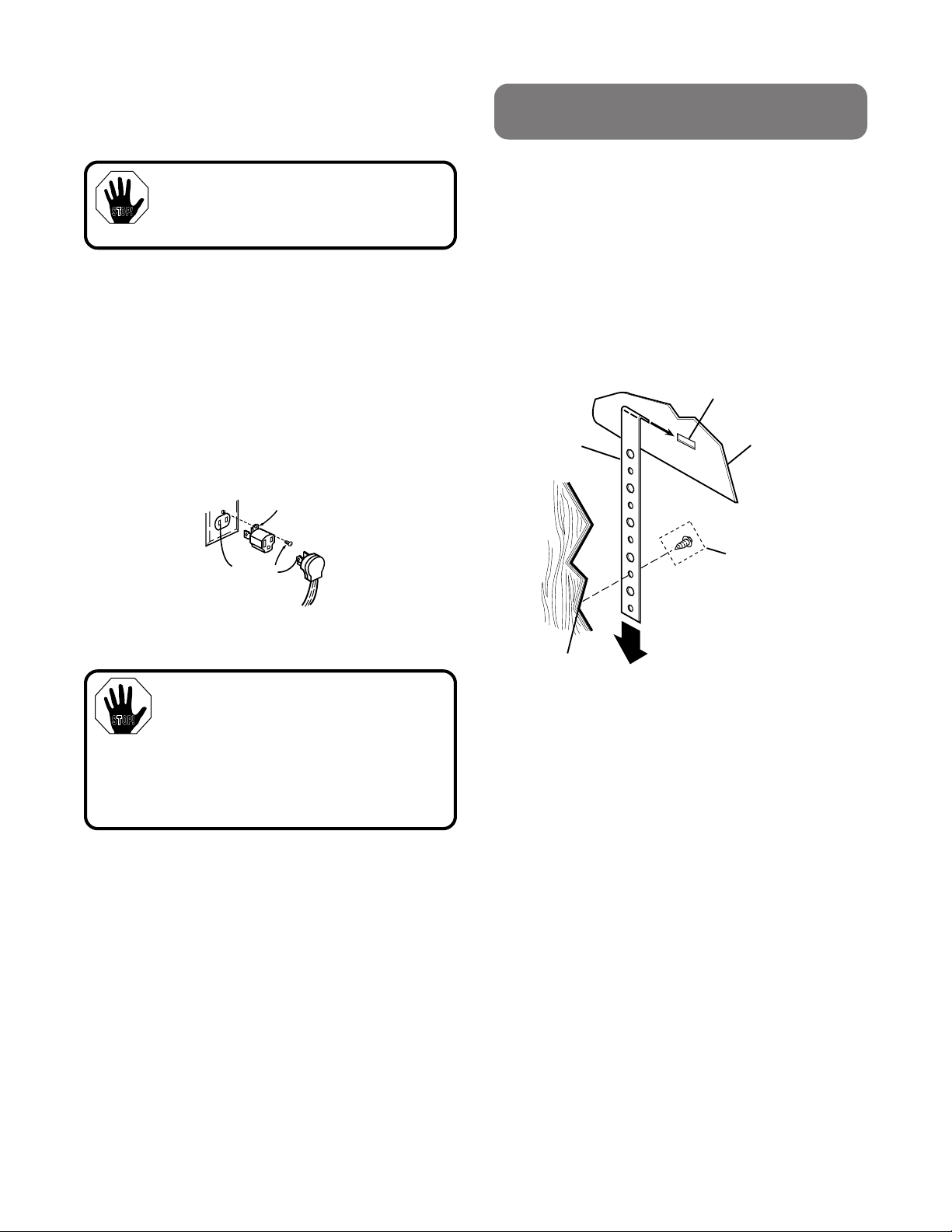
INSTALLING UNIT IN A
STANDARD OR TILE COUNTER
1.
Before installing the unit in the cutout, attach the
adhesive backed foam tape (shipped with unit). For
the Glass Cooktops attach the strip around the
bottom surface of the glass, near the edge of the
maintop. For Porcelain Cooktops attach the strip
around the edge of the metal flange.
2.
Attach the unit to the counter. Insert the hold down
brackets in the slots on each side of the unit.
3.
Use the screws supplied to attach unit to counter as
shown.The unit must rest on the metal flange around
the burner box and not on the glass.
HOLD DOWN
BRACKET
MOUNTING
SLOT
BURNER BOX
SIDES
USE SUITABLE
FASTENERS FOR
ANCHORING IN
CABINET SIDES
CABINET
SIDES
encountered, it is the personal responsibility and obligation of the customer to have it replaced with a
properly grounded three-prong wall receptacle.
Do not under any circumstances cut or remove grounding prong from cooktop cord.
Failure to provide proper polarization may
create a hazardous condition.
USAGE SITUATIONS WHERE APPLIANCE
POWER CORD WILL BE DISCONNECTED FREQUENTLY.
For 15 amp circuit only.
amp circuit. Where local codes permit, a
CONNECTION
Do not
use an adaptor on a 20
TEMPORARY
may be made to a properly grounded
two-prong wall receptacle by the use of a UL listed
adaptor available at most hardware stores. The larger
slot in the adaptor must be aligned with the large slot in
the wall receptacle to provide proper polarity in the
connection of the power cord.
Insure proper ground and
firm connection before use
When disconnecting the power cord from the adaptor,
always hold the adaptor with one hand. If this is not done
the adaptor ground terminal is very likely to break with
repeated use. Should this happen, DO NOT USE the
appliance until a proper ground has again been established.
Do not use an adaptor plug in these situations because
disconnection of the power cord places undue strain on
the adaptor and leads to eventual failure of the adaptor
ground terminal. The customer should have the twoprong wall receptacle replaced with a three-prong
(grounding) receptacle by a qualified electrician before
using the appliance.
Align large
prongs/slots
Temporary method
(Adaptor plugs not permitted
in Canada)
4
Page 5
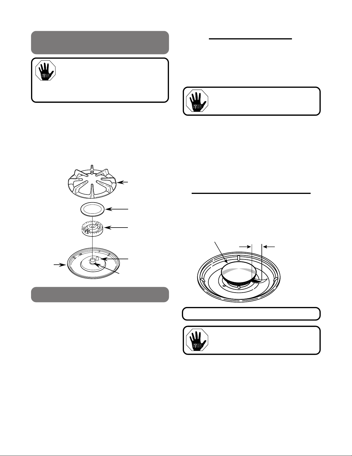
ASSEMBLING THE COOKTOP
STOP!
BURNER
BOWL
SPARK IGNITER
BURNER GRATE
BURNER CAP
BURNER HEAD
MIXER TUBE
(CHIMNEY)
CHECK THE IGNITERS
Operation of electric igniters should be checked after
cooktop and supply line connectors have been carefully checked for leaks and cooktop has been connected to electric power.
1.
Push and turn a burner valve to the LITE position.
a.
The burner valve should light when gas is
available to burner.
b.
Once the burner lights, it should be turned
out of the LITE position.
2.
Try each valve separately until all burners have
been checked.
BURNER IGNITION
COOKTOP SPARK IGNITION
- When you turn the
cooktop knob to LITE, the spark igniter makes a series
of electric sparks (ticking sounds) which light the burner.
During a power failure the burners will not light
automatically. In an emergency, a cooktop burner may
be lit with a match by following the steps below.
WARNING:
Lighting gas burners with a
match is dangerous. You should match light
the cooktop burners only in an emergency.
STOP!
Turn each burner on. Flames should be blue in color
with no trace of yellow. The burner flames should not
flutter or blow away from the burner. The inner cone of
the flame should be between 1/2" to 3/4" long.
1/2" to 3/4"
COOKTOP
BURNER
BURNERS SHOULD BE CHECKED FREQUENTLY
WARNING:
If you attempt to measure the
inner cone of the flame, please use caution.
Burns could result.
STOP!
BURNERS
The electrode of the spark igniter is exposed.
Be careful not to push any cooktop controls
while the top of the burner is removed. Do not
remove the top or touch the electrode of any
burner while another burner is turned on. Electrical
shock might result.
1.
Place the burner head on the burner bowl, so that
the location of the spark igniter matches up with
the opening in the burner head.
2.
Position the burner cap on the burner head.
3.
Place the burner grate over the burner assembly
and into the burner bowl. The bottoms of the
burner grates have fingers that fit into the
corresponding indentations in the burner bowl.
1.
Light a match and hold the flame near the burner
you want to light. Wooden matches work best.
2.
Push in and turn the control knob slowly. Be sure
you are turning the correct knob for the burner you
are lighting.
NOTE: If the burner does not light within five
seconds, turn the knob off and wait one
minute before trying again.
ABOUT THE BURNER FLAMES
5
Page 6

WHEN ALL HOOKUPS ARE
STOP!
COMPLETED
MAKING THE L.P.
Double check to make sure everything in this guide has
been completed. Rechecking steps will ensure safe
use of the cooktop.
MAKE SURE ALL CONTROLS ARE LEFT IN
THE OFF POSITION.
MAKE SURE THE FLOW OF COMBUSTION
AND VENTILATION AIR TO THE COOKTOP IS
UNOBSTRUCTED.
The serial plate for your cooktop is located on the
bottom of the burner box. In addition to the model and
serial numbers, it tells you the ratings of the burners and
type of fuel and pressure the cooktop was adjusted for
when it left the factory.
When ordering parts, always include the serial number,
model number and code letter to ensure proper replacement parts. Parts may be obtained through Sears
Service Centers or retail stores.
RECHECK STEPS
Double check to make sure everything in this guide has
been completed. Rechecking steps will ensure safe
use of the cooktop.
CONVERSION
The pressure regulator and the burner orifices are set
for natural gas. To use Propane Gas, the regulator and
burner orifices must be converted. The L.P. orifice
spuds for the cooktop burners can be located within a
bracket attached to the pressure regulator of this unit.
CAUTION:
the factory, is set for use with natural gas. If
you wish to use your unit with Liquefied
Petroleum (Propane) gas, you must first replace the
orifices and convert the pressure regulator.
WARNING:
This conversion must be performed by a
qualified installer or gas supplier in
accordance with the manufacturer's
instructions and all codes and requirements
of the authority having jurisdiction. Failure to
follow instructions could result in serious
injury of property damage. The qualified
agency performing this work assumes
responsibility for the conversion.
To adjust your cooktop for use with L.P. gas, follow
these instructions:
1.
Disconnect all electrical power, at the main circuit
breaker or fuse box.
2.
Shut off the gas supply to the cooktop by closing the
manual shut-off valve.
3.
Adjust the Pressure Regulator:
A.
Unscrew the cap.
B.
Place your thumb against the flat side of the
spring retainer and press down to remove the
retainer.
C.
Carefully look at the spring retainer to locate the
NAT or LP position.
The counter unit, as shipped from
6
Page 7

D.
NAT.
POSITION
L.P.
POSITION
CAP
SPRING
RETAINER
DOWN
FOR OFF
NAT
LP
LP
NAT
GASKET
PRESSURE REGULATOR
LP
NAT
NAT
LP
BURNER
BOWL
SPARK IGNITER
BURNER GRATE
BURNER CAP
BURNER HEAD
MIXER TUBE (CHIMNEY)
MIXER TUBE (CHIMNEY)
RETAINER
RING
GLASS COOKTOP
PORCELAIN COOKTOP
Turn the spring retainer over so that LP is
showing on the bottom.
E.
Snap the retainer back into position.
4.
Change the cooktop burner orifices:
A.
Remove the top grates, burner caps and burner
head.
IMPORTANT: Save these
orifices for future conversion
back to natural gas.
5.
Locate the L.P./Propane orifices.
The L.P./Propane orifices are shipped in the literature
package. They will have a digit number and the
letter “L” on one side.
Each orifice will also show a series of engraved
marks, (I, II or III), located on the top.
These marks denote the precise location of each orifice
to the cooktop burner.
B.
Using a 7mm or 9/32" nut driver, remove the top
burner orifices. These may be accessed
through the burner air/gas mixer tube (chimney).
NOTE: The orifices have a spring loaded retaining ring around the hex head to hold the
orifice in the nut driver during installation and
removal. A slight amount of force is required
to push the nut driver down over the ring.
6.
Install the L.P./Propane orifices in their precise
locations.
Return the natural orifices to the bracket and reattach
the bracket and the instruction sheet to the pressure
regulator using the screw previously removed.
7
Page 8

ADJUSTING BURNER FLAMES
STOP!
L
O
HI
OFF
LITE
RIGHT
BY-PASS SCREW
STOP!
CAUTION:
be made before turning on the burner. Failure
to do so could result in serious injury. Be
sure pressure regulator has been converted.
1.
Turn all burners full on and check the flames.
A.
They should be blue in color with no trace of
yellow. Foreign particles in the gas line may
cause an orange flame at first, but this will soon
disappear.
2.
To make adjustments, remove the control knobs
and panel. Insert a screwdriver in the shaft to
adjust the valve by-pass screw.
The following adjustments must
Once the conversion is complete
and checked ok, fill out the L.P.
sticker and include your name,
organization and date conversion was
made. Apply the sticker near the cooktop
gas inlet opening to alert others in the
future that this appliance has been
converted to L.P. If converting back to
natural gas from L.P., please remove the
sticker so others know the appliance is
set to use natural gas.
A.
If the flames were yellow or fluttered, open the
valve more than the original setting.
B.
If the flames blew away from the burner, close
the valve more than the original setting.
3.
Make the adjustment, by slowly turning the screw
until flame appearance is correct.
Adjust the low flame setting using the valve by-pass
screw as follows:
A.
Low setting adjustments must be made with
two other burners in operation on a medium
setting.
B.
This procedure prevents the low flame from
being set too low resulting in the flame being
extinguished when other burners are turned on.
TO CONVERT THE COOKTOP BACK
TO NATURAL GAS, REVERSE THE
STEPS UNDER MAKING THE L.P.
CONVERSION.
8
Pub. No. 31-10253
229C
4053P085
Page 9

INSTRUCCIONES PARA LA INSTALACION DE SU NUEVA
NO ALMACENE O USE GASOLINA U OTROS
GASES O LÍQUIDOS INFLAMABLES
CERCA DE ESTE O DE CUALQUIER OTRO
APARATO ELÉCTRICO.
QUE HACER SI HUELE GAS:
• No trate de encender ningún
aparato eléctrico.
• No toque ningún interruptor
eléctrico; no use ningún
teléfono en su edificio.
• Inmediatamente llame a su abastecedor de
gas desde el teléfono de un vecino. Siga las
instrucciones de su abastecedor de gas.
• Si no se puede comunicar con su
abastecedor de gas, llame a la compañía de
bomberos.
La instalación y el servicio debe hacerse por
un técnico calificado, agencia de servicio o el
abastecedor de gas.
STOP!
LISTA DE HERRAMIENTAS
• Punta de taladro de 1/8"
• Taladro eléctrico o manual
• Destornillador Phillips No.1
o No. 2
• Lápiz
• Regla
• Sierra manual o eléctrica
MATERIALES ADICIONALES QUE PODRIA
NECESITAR:
• Válvula de cierre para la línea del gas
• Sello para las uniones de cañerías
• Tubo de 1/2"
Para conexiones flexibles donde las permitan
los códigos locales:
• Tubería de metal flexible (3/4" o 1/2" igual que I.D. como
la línea del gas).
• Adaptador o unión.
Para conexión rígida:
• Encajes para tuberías que se requieran.
IMPORTANTE:
Saque todos los materiales de
empaque y la literatura de la cubierta para cocinar
antes de conectar el gas y la electricidad a la
estufa.
STOP!
CUBIERTA PARA COCINAR A GAS SELLADA DE 30"
Antes de empezar - Lea estas instrucciones completa y cuidadosamente.
IMPORTANTE - Guarde estas instrucciones para el uso del inspector local.
IMPORTANTE - CUMPLA CON TODOS LOS CODIGOS Y ORDENANZAS VIGENTES.
Nota al instalador - Asegúrese de dejar estas instrucciones con el consumidor.
Nota al consumidor - Guarde estas instrucciones con su Manual de Uso y Cuidado para referencia
futura.
Este aparato debe hacer tierra adecuadamente.
• La instalación de esta cubierta para cocinar debe cumplir
PARA SU SEGURIDAD
¡¡ADVERTENCIA!! Si la información
en este manual no se sigue
exactamente, podría resultar en
un incendlo o una explosión que
cause daño a la propiedad, heridas
personales o muerte.
con los códigos locales, o en la ausencia de códigos
locales con el National Fuel Gas Code, ANSI Z223, 1Latest edition.
• Asegúrese que su estufa sea instalada adecuandamente
por un instalador competente o por un técnico de servicio.
• Para eliminar tener que alcanzar algo por encima de los
quemadores de la superficie, se debería evitar guardar
cosas en los gabinetes que están encima de la cubierta.
• No instale la unidad cerca de una puerta que dé hacia
afuera o donde una corriente de aire pueda afectar su uso.
• Llave inglesa para
cañerías
• LLave inglesa
ajustable
• Soquete hexagonal de
3/16"
• Nivel de espíritu de 12"
El diseño de esta cubierta para cocinar ha sido certificado por
la Asociación de Gas Americana. Usted encontrará
precauciones de seguridad en su libro de Uso y Cuidado.
Léalas cuidadosamente.
Pub. No. 31-10253
229C
4053P085
1
Page 10

REQUERIMIENTOS ELECTRICOS
28 3/8
21
30
28 1/2
14 1/4
3
2 1/4
3 1/4
19 1/2
CUBIERTA PARA COCINAR
19 3/8
12 1/2"
DESDE LINEA
DE CENTRO
DEL CORTE
1" DESDE PARED TRASERA
30" MIN AL
GABINETE
.
3 3/4" MIN. DE
ESPACIO A PARED DEL LADO
18" MIN.
AL GABINETE
13" PROFUNDIDAD MAX.
3 3/4" MIN. DE
ESPACIO A PARED
DEL LADO
PROVEA UN ABASTECIMIENTO
DE GAS ADECUADO
Esta cubierta está diseñada para funcionar con gas natural a 4"
de presión columna de agua. Sale de fábrica programada para
gas natural.
Un regulador de presión convertible está conectado en series
con el conjunto de cañerías de la cubierta y debe permanecer
en series con la línea abastecedora sin importar si el gas que
se está usando es natural o L.P.
PARA UN FUNCIONAMIENTO ADECUADO, LA
PRESION MAXIMA DE ENTRADA AL REGULADOR
NO DEBE SER MAYOR A 14" DE PRESION COLUMNA
DE AGUA.
Para probar el regulador, la presión de entrada
debe ser por lo menos 1" (o 3.4 KPA) más que la posición de
salida del regulador. Si el regulador está puesto para 4" de
presión columna de agua, la presión de entrada debe ser de
por lo menos 5". Si el regulador está puesto para 10", la
presión de entrada debe ser de por lo menos 11".
La línea abastecedora del gas a la cubierta debería ser una
cañería de 1/2" o 3/4".
"
"
"
"
"
"
" "
"
5/8
"
Este aparato debe hacer tierra. Consulte los códigos
locales que se aplican en su área. Si no existen códigos
locales, debe cumplir con el National Electrical Code,
ANSI/NFPA No. 70-Latest Edition. Escriba a:
NATIONAL FIRE PROTECTION ASSOCIATION
BATTERYMARCH PARK
QUINCY, MA 02269
Asegúrese que la instalación de esta cubierta para cocinar en
una casa móvil cumpla con el Manufactured Home
Construction and Safety Standard, Title 24 CFR, Part 3280. Si
esta norma no es aplicable, usted debe cumplir con las
normas para Manufactured Home Installations 1982
(Manufactured Home Site, Communities and Set-ups, ANSI
A225.1-Latest Edition) o códigos locales. Escriba a:
Office of Mobile Home Standards
HUD Building
451 7th Street, S.W.
Washington, D.C. 24010
COMO PREPARAR LA ABERTURA
• Asegúrese que todos los revestimientos de paredes,
mesón y gabinetes alrededor de la cubierta para cocinar
°
pueden soportar el calor (hasta 200
F) generado por la
cubierta para cocinar.
• Provea espacios adecuados entre la cubierta para cocinar
y las superficies combustibles adyacentes.
2
Page 11

CONEXIONES DEL GAS
ELE DE 90°
CODO DE 45°
LADOS DEL
GABINETE
HOYO DE 2" DE DIAM.
(20 7/8" DEL FRENTE
DEL MESON AL
CENTRO DEL HOYO)
5" AL CENTRO DEL
HOYO DE 2" DE DIAM.
DESDE SUPERFICIE
DEL MESON
REQUERIMIENTOS ELECTRICOS
Debido al posible peligro bajo ciertas condiciones,
recomendamos categóricamente no usar un cordón de
extensión. Sin embargo, si usted aún decide usar un cordón
de extensión, es absolutamente necesario que sea un cordón
de extensión para aparatos eléctricos de 3 alambres que
haga tierra que esté en la lista de UL, y que la capacidad de
conducción de corriente en amperes sea equivalente o
mayor a la capacidad del circuito. Tales cordones de extensión
se pueden obtener a través del vendedor de aparatos
eléctricos de su localidad.
IMPORTANTE:
(Por favor lea cuidadosamente)
PARA SU SEGURIDAD PERSONAL, ESTE APARATO
DEBE HACER TIERRA ADECUADAMENTE.
STOP!
L
N
STOP!
3" MIN.
CORTE DE
19 5/8"
CODO DE 45°
REGULADOR
DE PRESION
VALVULA
DE CIERRE
CAÑERIA
DE 1/2"
UNION
CORDON
ELECTRICO
RECEPTACULO
ELECTRICO
¡NO USE UNA LLAMA PARA VER SI
EXISTEN ESCAPES!
STOP!
1.
Conecte la cubierta a la línea abastecedora de gas.
2. NUNCA REUSE CONECTORES VIEJOS O
USADOS CUANDO INSTALE UNA ESTUFA
NUEVA.
PARA LA INSTALACION SOBRE UN
HORNO EMPOTRADO (BUILT-IN):
Vea cómo se instala un Horno de tipo “Built-In” (Empotrado)
para instrucciones completas.
PRECAUCION:
Nunca reutilice conectores flexibles
viejos. El uso de conectores flexibles viejos puede
causar escapes de gas y heridas personales. Siempre
utilice conectores nuevos cuando instale una estufa a gas.
3.
El regulador que se provee con la unidad debe ser
instalado en la línea del gas entre la válvula de cierre y
la conexión de la unidad. La parte superior del regulador
debería mirar hacia el frente del gabinete y tener un fácil
acceso a través de las puertas del gabinete.
4.
Instale una válvula de cierre manual en la línea
abastecedora en un lugar fácilmente accesible.
Asegúrese de saber cómo y dónde cerrar el paso del
gas a la cubierta para cocinar.
5.
Revise que no hayan escapes. Después de conectar la
estufa al gas, revise el sistema para que no hayan
escapes con un manómetro. Si no tiene un manómetro
disponible, abra el paso del gas a la estufa y use un
detector de escapes líquido en todas las uniones y
conexiones para ver que no existan escapes.
Apriete todas las conexiones si es necesario para prevenir
escapes de gas en la cubierta o en la línea abastecedora de
gas.
Revise el alineamiento de las válvulas después de conectar
la estufa a la línea del gas para estar seguro que el tubo del
conjunto de cañerías no ha sido movido. Un mal alineamiento
podría causar que el tallo de la válvula roce contra el panel
de control, resultando en un escape de gas en la válvula.
Desconecte la estufa del sistema abastecedor de
gas cerrando su válvula de cierre individual
cualquier prueba del sistema abastecedor de gas a presiones
de prueba igual o menor de 1/2" psig.
La estufa debe ser aislada del sistema
abastecedor
durante cualquier prueba de presión al sistema abastecedor
de gas a presiones de prueba igual o menor de 1/2" psig.
durante
de gas cerrando su válvula de cierre individual
Se debe usar una línea de corriente y un receptáculo adecuado
para operar las partes eléctricas de su estufa.
1.
El cordón eléctrico de este aparato está equipado con un
enchufe de tres patas (para hacer tierra) el cual se debe
usar con un receptáculo de tres hoyos que haga tierra
adecuadamente con corriente alterna normal de casa de
120 voltios, 60 ciclos.
2.
Si usted no tiene un receptáculo de tres hoyos que haga
tierra adecuadamente, haga que un electricista le cambie
el viejo.
3.
Se necesitará un adaptador para convertir el viejo hasta
que el receptáculo pueda ser reemplazado. Este método
es solamente provisorio, y un electricista calificado
debería probarlo para estar seguro que cumple con los
requerimientos.
Asegúrese que haga
tierra bien y que esté
conectado firmemente
antes de usarlo.
3
Page 12

Donde exista un receptáculo de pared para un enchufe de
STOP!
STOP!
COMO INSTALAR UNA UNIDAD
EN UN MESON NORMAL O DE
BALDOSA
1.
Antes de instalar la unidad en el corte, pegue la cinta
adhesiva de espuma (viene con la unidad) alrededor de
la superficie del fondo del vidrio, cerca de la orilla de la
superficie principal.
2.
Pegue la unidad al mesón como se muestra. Inserte las
abrazaderas para sujetarla en las ranuras a cada lado
de la unidad.
3.
Use los tornillos que se le proveen para pegar la unidad
al mesón como se muestra. La unidad debe descansar
sobre la falange de metal alrededor de la caja del
quemador y no sobre el vidrio.
ABRAZADERA
RANURA DE MONTAJE
LADOS DE LA CAJA
DEL QUEMADOR
USE SUJETADORES
ADECUADOS PARA
ANCLAR EN LOS
LADOS DEL GABINETE
LADOS DEL
GABINETE
dos patas, es la responsabilidad y la obligación del cliente
de reemplazarlo con un receptáculo de pared para tres
patas que haga tierra adecuadamente.
NO, BAJO NINGUNA CIRCUNSTANCIA, CORTE O SAQUE
LA TERCERA PATA (QUE HACE TIERRA) DEL CORDON
ELECTRICO. LA FALLA DE PROVEER UNA
POLARIZACION ADECUADA PODRIA CREAR UNA
CONDICION PELIGROSA.
SITUACIONES DE USO CUANDO EL CORDON
ELECTRICO DE LA ESTUFA SE DESCONECTARA
FRECUENTEMENTE.
Para circuitos de 15 amp. solamente. No use un adaptador
en un circuito de 20 amp. Donde los códigos locales lo
permitan, se puede hacer una
conexión provisoria
a un
receptáculo de pared de dos patas que haga tierra
adecuadamente con un adaptador aprobado por UL que se
puede obtener en la mayoría de las ferreterías. La ranura más
grande del adaptador debe estar en línea con la ranura
grande del receptáculo de pared para proveer una polaridad
adecuada en la conexión del cordón eléctrico.
Asegúrese que
haga tierra bien y
que esté conectado
firmemente antes
Ponga en línea las
patas/ranuras
grandes
de usarlo.
Método provisorio
(Los adaptadores de enchufes no se permiten en
Canadá)
PRECAUCION:
El conectar el terminal para
hacer tierra del adaptador al tornillo de la cubierta
del receptáculo de pared no hace que la estufa
haga tierra a menos que el tornillo sea de metal
y no esté aislado, y que el receptáculo de pared haga tierra
a través del alambrado de la casa. El cliente debería hacer
que un electricista competente revise el circuito para estar
seguro que el receptáculo hace tierra adecuadamente.
Cuando desconecte el cordón eléctrico del adaptador, siempre
sujete el adaptador con una mano. Si esto no se hace, es
posible que el terminal para hacer tierra del adaptador se
quiebre con el uso repetido. Si esto sucede, NO USE el aparato
hasta que nuevamente haga tierra adecuadamente.
SITUACIONES DE USO CUANDO EL CORDON
ELECTRICO DE LA ESTUFA SE DESCONECTARA
FRECUENTEMENTE.
No use un adaptador para el enchufe en estas situaciones
porque la desconexión del cordón eléctrico ejerce demasiado
trabajo sobre el adaptador y conduce a la falla del terminal
para hacer tierra del adaptador. El cliente debería hacer
reemplazar el receptáculo de pared para dos patas con un
receptáculo de pared para tres patas (que haga tierra) a
través de un electricista competente antes de usar la estufa.
4
Page 13

COMO ARMAR LOS
STOP!
REVISE LOS ENCENDEDORES
El funcionamiento de los encendedores debería ser revisado
después que la cubierta para cocinar y la línea abastecedora
de gas hayan sido cuidadosamente revisadas para que no
existan escapes de gas y la cubierta para cocinar haya sido
conectada a la electricidad.
1.
Empuje y haga girar la válvula de un quemador a la
posición LITE (ENCENDIDO).
A.
La válvula de quemador se debería encender cuando
el gas pasa al quemador.
B.
Una vez que el quemador se encienda, se debería
sacar de la posición LITE.
2.
Pruebe cada válvula separadamente hasta que todos los
quemadores hayan sido revisados.
ENCENDIDO DE LOS QUEMADORES
ENCENDIDO A CHISPA DE LOS QUEMADORES —
Cuando usted coloca la perilla de la cubierta en LITE, el
encendedor a chispa produce una serie de chispas eléctricas
(sonidos tic tac) que encienden el quemador.
Durante un corte de corriente, los quemadores no se
encenderán automáticamente. En caso de emergencia, un
quemador de superficie puede ser encendido con un fósforo
siguiendo los pasos de más abajo:
1.
Prenda un fósforo y sujete la llama cerca del quemador
que desea encender. Los fósforos de madera funcionan
mejor.
2.
Empuje y haga girar la perilla de control lentamente. Esté
seguro de hacer girar la perilla del quemador que está
encendiendo.
NOTA: Si el quemador no se enciende dentro
de cinco segundos, apague la perilla y espere
un minuto antes de tratar nuevamente.
LLAMAS DE LOS QUEMADORES
Encienda cada uno de los quemadores. Las llamas deberían
ser de color azul sin muestras de amarillo. Las llamas no
deberían pestañear o soplar en dirección opuesta al quemador.
El cono interno debería tener entre 1/2" a 3/4" de longitud.
1/2" to 3/4"
QUEMADOR DE SUPERFICIE
LOS QUEMADORES DEBERIAN SER REVISADOS
FRECUENTEMENTE
STOP!
RECIPIENTE
DEL QUEMADOR
ENCENDEDOR A CHISPA
PARRILLA DEL QUEMADOR
TAPA DEL QUEMADOR
CABEZA DEL QUEMADOR
TUBO DE MEZCLA (CHIMENEA)
STOP!
QUEMADORES DE LA
SUPERFICIE
El electrodo del encendedor a chispa está
expuesto y el tubo de mezcla podría tener orillas
afiladas. Tenga cuidado de no empujar ninguno
de los controles de la cubierta cuando se saca la
tapa del quemador. No saque la tapa o toque el
electrodo de ningún quemador mientras otro quemador está
encendido. Podría resultar en un golpe de corriente.
1.
Coloque la cabeza del quemador sobre el recipiente del
quemador, de manera que la posición del encendedor a
chispa coincida con la abertura en la cabeza del quemador.
2.
Coloque la tapa del quemador sobre la cabeza del
quemador.
3.
Coloque la parrilla del quemador sobre el conjunto del
quemador y sobre el recipiente del quemador. Los fondos
de las parrillas de los quemadores tienen puntas que
encajan en las indenciones correspondientes en los
recipentes de los quemadores.
ADVERTENCIA: El encender los quemadores a gas
con un fósforo es peligroso. Usted debería prender los
quemadores de la cubierta para cocinar con un fósforo
sólo en caso de emergencia
ADVERTENCIA:
de la llama, por favor tenga cuidado.
Podría quemarse.
Si trata de medir el cono interior
5
Page 14

CUANDO TODAS LAS
STOP!
CONEXIONES HAYAN SIDO
COMPLETADAS
Revise bien para estar seguro que todo en esta guía ha sido
completado. Revisando los pasos asegurará el uso seguro
de la estufa.
ASEGURESE QUE TODOS LOS CONTROLES SE DEJEN EN
POSICION DE APAGADO.
ASEGURESE QUE EL PASO DE LA COMBUSTION Y LA
VENTILACION NO ESTEN OBSTRUIDOS.
La placa con el número de serie de su cubierta para cocinar
está ubicada en el fondo de la caja del quemador. Además
del número de modelo y serie, le dice los valores de los
quemadores y el tipo de combustible y presión a los cuales
la cubierta de cocinar fue ajustada cuando salió de la fábrica.
Cuando ordene partes, siempre incluya el número de serie,
número de modelo y la letra de código para estar seguro de
obtener las partes de repuestos correctas. Las partes se
pueden obtener a través de los Centros de Servicio o Tiendas
Sears.
REVISE LOS PASOS
Revise bien para asegurarse que todo en esta guía ha sido
completado. La revisión de los pasos asegurará el uso seguro
de la cubierta para cocinar.
COMO AJUSTAR PARA
USAR GAS PROPANO
El regulador de presión está programado para gas natural.
Para usar gas propano, el regulador debe ser convertido.
Los orificios para gas L.P. para los quemadores de la
cubierta pueden ser localizados dentro de una abrazadera
pegada al regulador de la presión de esta unidad.
PRECAUCION:
fábrica, está programada para funcionar con gas
natural. Si desea usar su unidad con gas de Petróleo
Liquido (Propano), usted debe primeramente
reemplazar los orificios y convertir el regulador de presión
como se describe más abajo.
ADVERTENCIA:
Esta conversión debe ser hecha por un instalador
competente o por el abastecedor de gas de acuerdo
con las instrucciones del fabricante y todos los
códigos y requerimientos de las autoridades que
tienen jurisdicción. El no seguir las instruccion es
podría resultar en serias heridas o en daño a la
propiedad. La agencia competente que hacer este
trabajo asume la responsabilidad por la conversión.
Para ajustar su estufa para ser usada con gas L.P., siga estas
instrucciones:
1.
Desconecte todo el poder eléctrico, en el interruptor del
circuito principal o la caja de los fusibles.
2.
Corte el paso del gas a la estufa cerrando la válvula de
cierre manual.
3.
Ajuste el regulador de presión como sigue:
A.
Desatornille la tapa.
B.
Coloque el pulgar contra el lado plano del sujetador
del resorte y empuje hacia abajo para soltar el
sujetador.
C.
Mire cuidadosamente para ubicar las posiciones
NAT o L.P.
La unidad de mesón, como sale de
6
Page 15

7
D.
Haga girar el sujetador del resorte hasta que
L.P. se vea en el fondo.
E.
Ponga nuevamente el sujetador en posición.
POSICION NAT
POSICION L.P./PROPANO
TAPA
SUJETADOR
DE RESORTE
DOWN
FOR OFF
NAT
LP
LP
NAT
SELLO
REGULADOR DE PRESION
LP
NAT
NAT
LP
RECIPIENTE
DEL QUEMADOR
ENCENDEDOR A CHISPA
PARRILLA DEL QUEMADOR
TAPA DEL QUEMADOR
CABEZA DEL QUEMADOR
TUBO DE MEZCLA (CHIMENEA)
MIXER TUBE (CHIMNEY)
NOTA: Los orificios tienen un anillo de retención
alrededor de la cabeza hexagonal cargado con un
resorte para sujetar el orificio en el apretador de
tuercas cuando se instala o se saca. Una leve
fuerza se requiere para empujar el apretador de
tuercas sobre el anillo.
RETAINER
RING
ANILLO DE RETENCION
IMPORTANTE:
Guarde estos
orificios para una futura
conversión de vuelta a gas
natural.
5.
Ubique los orificios L.P.
Los orificios se envían en el paquete de la literatura.
Tendrán un número y la letra “L” en un lado.
Cada orificio también tendrá una serie de marcas
grabadas, (I, II, III), ubicadas en la parte superior.
4.
Cambie los orificios de los quemadores de la cubierta:
A.
Sacando las parrillas, las tapas y las cabezas de los
quemadores.
B.
Usando un apretador de tuercas de 7mm o 9/32",
saque los orificios de los quemadores superiores.
Estos se pueden alcanzar a través del tubo de
mezcla de aire/gas (chimenea).
Estas marcas indican la ubicación precisa de cada orificio en
el quemador de la cubierta.
CUBIERTA DE VIDRIO
6.
Instale los orificios L.P. en sus lugares precisos.
CUBIERTA DE PORCELANA
TUBO DE MEZCLA
(CHIMENEA)
Coloque los orificios para gas natural de vuelta en la
abrazadera y pegue nuevamente la abrazadera y la hoja
con las instrucciones al regulador de la presión usando el
tornillo que se sacó previamente.
Page 16

STOP!
COMO HACER LOS AJUSTES
A LA LLAMA DEL QUEMADOR
L
O
HI
OFF
LITE
RIGHT
BYPASS SCREW
TORNILLO DE PASO DE
VALVULA
A.
Si las llamas son amarillas y pestañean, abra el
obturador más que la posición original.
B.
Si las llamas soplan en dirección opuesta al
quemador, cierre el obturador más que la posición
original.
3.
Haga los ajustes haciendo girar lentamente el tornillo
hasta que la apariencia de la llama sea correcta.
Ajuste la posición baja de la llama usando el tornillo de la
válvula de paso como sigue:
A.
Los ajustes de llama baja se deben hacer con
los otros dos quemadores operando a llama
mediana.
B.
Este procedimiento previene que la llama baja
se ponga en una posición demasiado baja que
resulte en que la llama se apague cuando los
otros quemadores se enciendan.
El regulador de presión está programado para
gas natural. Para usar gas propano, el
regulador debe ser convertido.
229C
4053P085
Pub. No. 31-10253
STOP!
PRECAUCION:
hacer antes de encender el quemador. Si no los
hace podría resultar en heridas de gravedad.
Asegúrese que el regulador de la presión ha sido
convertido.
1.
Encienda completamente todos los quemadores y revise
las llamas.
A.
Deberían ser de color azul sin muestras de
amarillo. Las partículas extrañas en la línea del gas
podrían causar una llama anaranjada al
principio, pero esto desaparecerá pronto.
2.
Para hacer los ajustes, saque las perillas de control y el
panel. Inserte un destornillador en el tallo para ajustar el
tornillo de la válvula de paso.
Los siguientes ajustes se deben
Una vez que la conversión haya sido
completada y esté funcionando bien,
llene la etiqueta L.P. e inculya su
nombre, organización y la fecha en
que la conversión fue hecha. Pegue la
etiqueta cerca de la entrada de la línea del gas
a la estufa para advertir a otros en el futuro que
esta estufa ha sido convertida para funcionar
con gas L.P. Si se convierte de gas L.P. para ser
usada nuevamente con gas natural, por favor
saque la etiqueta para que otros sepan que esta
estufa está programada para funcionar con gas
natural.
8
 Loading...