

Page 1
GE Consumer & Industrial
Technical Service Guide
JUNE 2006
Advantium 120
31-9141
SCB 1000
SCB 1001
ZSC 1000
ZSC 1001
GE Appliances
General Electric Company
Louisville, Kentucky 40225
– 1 –
Page 2

IMPORTANT SAFETY NOTICE
The information in this service guide is intended for use by
individuals possessing adequate backgrounds of electrical,
electronic, and mechanical experience. Any attempt to repair a
major ap pli ance may result in personal injury and property
damage. The man u fac tur er or seller cannot be responsible for the
in ter pre ta tion of this in for ma tion, nor can it assume any liability in
connection with its use.
WARNING
To avoid personal injury, disconnect power before servicing
this prod uct. If electrical power is required for diagnosis or test
purposes, disconnect the power immediately after performing the
necessary checks.
RECONNECT ALL GROUNDING DEVICES
If grounding wires, screws, straps, clips, nuts, or washers used to
complete a path to ground are removed for service, they must be
returned to their original position and properly fastened.
GE Consumer & Industrial
Technical Service Guide
Copyright © 2006
All rights reserved. This service guide may not be reproduced in whole or in part
in any form without written permission from the General Electric Company.
– 2 –
(Continued next page)
Page 3

PRECAUTIONS TO BE OBSERVED BEFORE AND DURING SERVICING TO
AVOID POSSIBLE EXPOSURE TO EXCESSIVE MICROWAVE ENERGY.
A. DO NOT OPERATE OR ALLOW THE OVEN TO BE OPERATED WITH THE
DOOR OPEN.
B. IF THE OVEN OPERATES WITH THE DOOR OPEN, INSTRUCT THE USER
NOT TO OPERATE THE OVEN AND CONTACT THE MANUFACTURER
IMMEDIATELY.
C. MAKE THE FOLLOWING SAFETY CHECKS ON ALL OVENS TO BE
SERVICED BEFORE ACTIVATING THE MAGNETRON OR OTHER
MICROWAVE SOURCE, AND MAKE REPAIRS AS NECESSARY:
1. INTERLOCK OPERATION.
2. PROPER DOOR CLOSING.
3. SEAL AND SEALING SURFACES (ARCING, WEAR AND OTHER
DAMAGE).
4. DAMAGE TO OR LOOSENING OF HINGES AND LATCHES.
5. EVIDENCE OF DROPPING OR ABUSE.
D. BEFORE TURNING ON MICROWAVE POWER FOR ANY TEST OR
INSPECTION WITHIN THE MICROWAVE GENERATING COMPARTMENTS,
CHECK THE MAGNETRON, WAVE GUIDE OR TRANSMISSION LINE AND
CAVITY FOR PROPER ALIGNMENT, INTEGRITY AND CONNECTIONS.
E. ANY DEFECTIVE OR MISADJUSTED COMPONENTS IN THE INTERLOCK
MONITOR, DOOR SEAL AND MICROWAVE GENERATION AND
TRANSMISSION SYSTEMS SHALL BE REPAIRED, REPLACED OR
ADJUSTED BY PROCEDURE DESCRIBED IN THIS MANUAL BEFORE THE
OVEN IS RELEASED TO THE OWNER.
F. A MICROWAVE LEAKAGE CHECK TO VERIFY COMPLIANCE WITH THE
FEDERAL PERFORMANCE STANDARD SHOULD BE PERFORMED ON
EACH OVEN PRIOR TO RELEASE TO THE OWNER.
– 3 –
Page 4

Table of Contents
Blower Assembly ..............................................................................................................................................................32
Capacitor and Diode .......................................................................................................................................................30
Cavity Light ..........................................................................................................................................................................29
Components ........................................................................................................................................................................22
Component Access Chart ............................................................................................................................................22
Component Locator Views ...........................................................................................................................................15
Control Boards and Panel Connections .................................................................................................................19
Control Panel Assembly .................................................................................................................................................25
Control Features ............................................................................................................................................................... 8
Convection Heater Assembly and Thermistor ....................................................................................................35
Damper Assembly ............................................................................................................................................................ 32
Demo Mode .........................................................................................................................................................................42
Diagnostics and Service Information ......................................................................................................................41
Door Assembly ...................................................................................................................................................................24
Fault Codes ..........................................................................................................................................................................42
Fuse ........................................................................................................................................................................................29
High Voltage Transformer ............................................................................................................................................31
Humidity Sensor ................................................................................................................................................................37
Installation ...........................................................................................................................................................................14
Introduction ......................................................................................................................................................................... 6
Left and Right Door Switch Assemblies ..................................................................................................................38
Lower Heater Assembly ................................................................................................................................................35
Low Voltage Transformer .............................................................................................................................................28
Magnetron and Magnetron TCO ................................................................................................................................31
Microwave Leak Test .......................................................................................................................................................43
Noise Filter ........................................................................................................................................................................... 30
Nomenclature .................................................................................................................................................................... 5
Oven Removal / Partial Removal ............................................................................................................................... 23
Proof Feature ......................................................................................................................................................................43
Schematics and Wiring Diagrams ............................................................................................................................44
Speed Cook System .........................................................................................................................................................10
Standard Test Load ..........................................................................................................................................................42
Turntable Motor ................................................................................................................................................................. 37
Upper Heater and Oven Cavity TCOs ...................................................................................................................... 33
Upper Heater Assembly ................................................................................................................................................ 34
Warranty .............................................................................................................................................................................. 46
– 4 –
Page 5
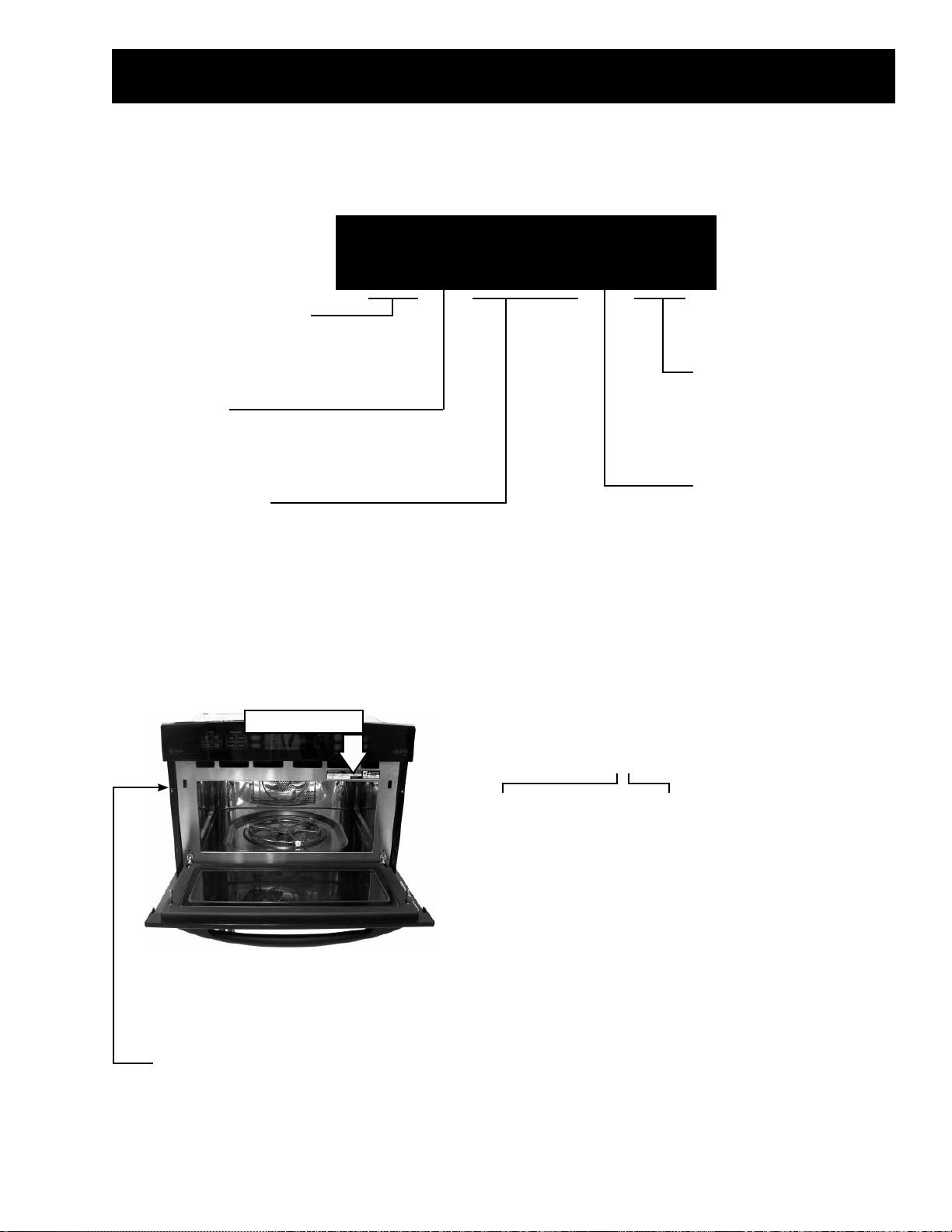
Model Number
Nomenclature
S C B 1 0 0 0 D B B
GE Speedcook Technology
SC =GE Profi le
ZS = Monogram
Confi guration
B = Wall Oven
C = Monogram Wall Oven
Model Designator
1000 = Color Model
1001 = Stainless Steel Model
Nomenclature
Exterior Color
BB = Black
CC = Bisque
SS = Stainless Steel
WW = White
Model Year Designator
Serial Number
The fi rst two characters of the serial number
identify the month and year of manufacture.
Example: AL123456S = January, 2006
The nomenclature plate is lo cat ed
on the inside door frame.
The mini-manual is located behind
the small access panel on the left
side of the oven.
A - JAN 2006 - L
D - FEB 2005 - H
F - MAR 2004 - G
G - APR 2003 - F
H - MAY 2002 - D
L - JUN 2001 - A
M - JUL 2000 - Z
R - AUG 1999 - V
S - SEP 1998 - T
T - OCT 1997 - S
V - NOV 1996 - R
Z - DEC 1995 - M
– 5 –
The letter des ig nat ing
the year re peats every
12 years.
Example:
T - 1974
T - 1986
T - 1998
Page 6
Introduction
The new Advantium oven uses breakthrough Speedcook technology to harness the power of light. The
Advantium oven cooks the outside of foods much like conventional radiant heat, while also penetrating the
surface so the inside cooks simultaneously. While halogen light is the primary source of power, a "microwave
boost” is added with certain foods. Foods cook evenly and fast, retaining their natural moisture.
Features and Benefi ts
Speedcook Oven - Delivers oven quality food up to four times faster than a conventional oven. No
preheating required.
True European Convection Oven - 1500 watt convection oven mode bakes and roasts at temperatures
ranging from 80 to 450°F.
Sensor Microwave Oven - 975 watt sensor microwave oven mode automatically delivers perfect cooking
results.
Warming Oven - Keeps prepared foods warm and fresh, and retains perfect moistness and crispness.
Proof Feature - Specialized mode allows dough to rise quickly.
16-in. Turntable - Removable metal and glass trays easily handle large casserole dishes.
Rounded Rear Wall - Allows complete turntable rotation of 9-in. x 13-in. casserole dish for even cooking.
Installation Flexibility - Fits either a 27-in. x 30-in. wall oven cabinet (installation kit included).
Pre-programmed Recipes - Provide quick and easy programming of over 175 speedcook food selections.
Multi-Level Cooking - Removable rack allows cooking of multiple dishes at once.
Non-Stick Cooling Tray - 16-in. Speedcook tray cleans up easily.
– 6 –
(Continued Next Page)
Page 7
OPTIONS
HELP
POWER
TEMP
BACK
CLEAR
OFF
START
PAUSE
T
U
R
N
T
O
S
E
L
E
C
T
P
R
E
S
S
T
O
E
N
T
E
R
FAN MSG REM MUTE TIMER
TIMER
FAVORITE
RECIPES
MICROWAVE
REHEAT
EXPRESS
DEFROST
COOK
OVEN
WARM
PROOF
BAKE
BROIL
CUSTOM
SPEED COOK
SPEED
COOK
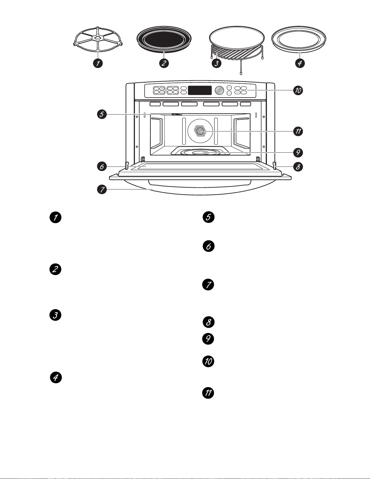
Turntable
The turntable must always be in
place, on the oven floor, for all
cooking. Be sure the turntable is
seated securely over the spindle
in the center of the oven.
Non-stick Metal Tray
Put food directly on the non-stick
metal tray and place on the turntable
when using the speedcook and bake
features.
Wire Oven Rack and Aluminum
Baking Sheet
Put food directly on the aluminum
baking sheet on the wire oven rack,
and place them on the non-stick
metal tray, when baking on two levels,
broiling or toasting foods.
Clear Glass Tray
Place on the turntable when using
the microwave features. Place food or
microwave-safe cookware directly on
the tray.
Upper Halogen Lamp/Ceramic Heater
Operates when using speedcook or
broil.
Window
Allows cooking to be viewed while
keeping microwaves confined in
the oven.
Door Handle
Pull to open the door. The door
must be securely latched for the
oven to operate.
Door Latches
Lower Ceramic Heater
Operates when using speedcook.
Control Panel
The pads used to operate the oven
are located on the control panel.
Rear Convection Heat Element
Operates when using bake.
– 7 –
Page 8
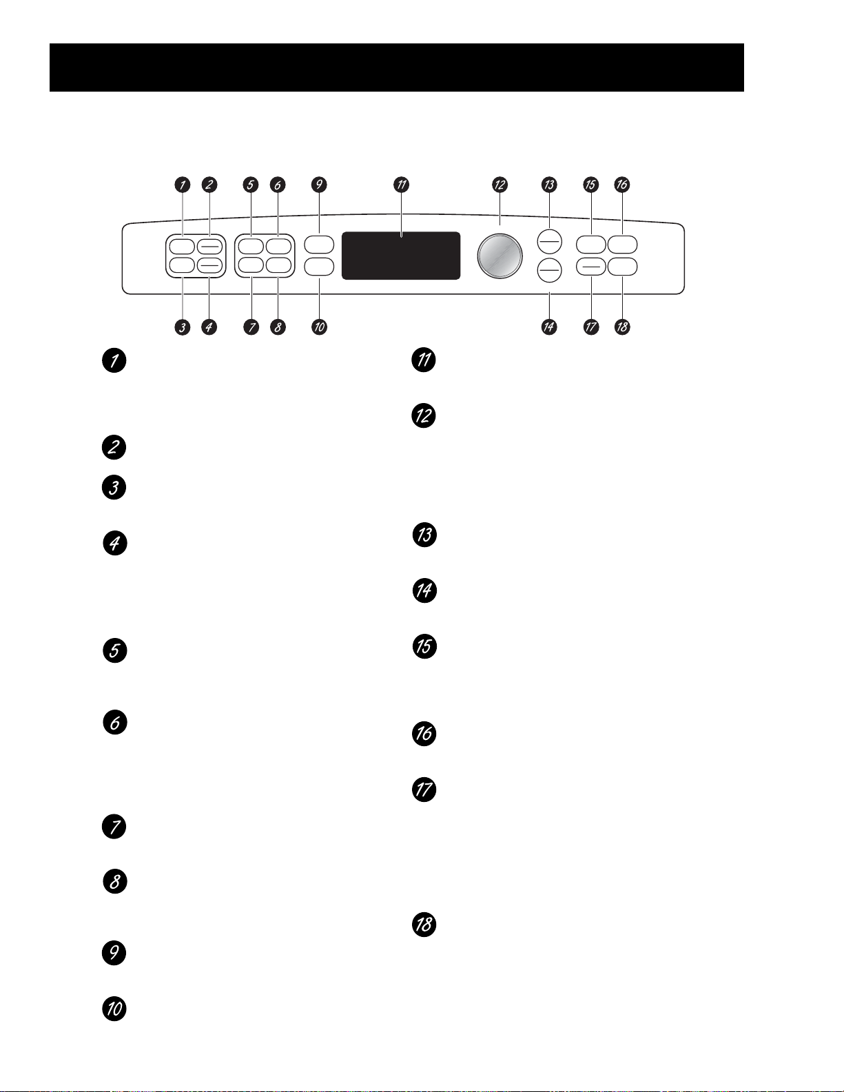
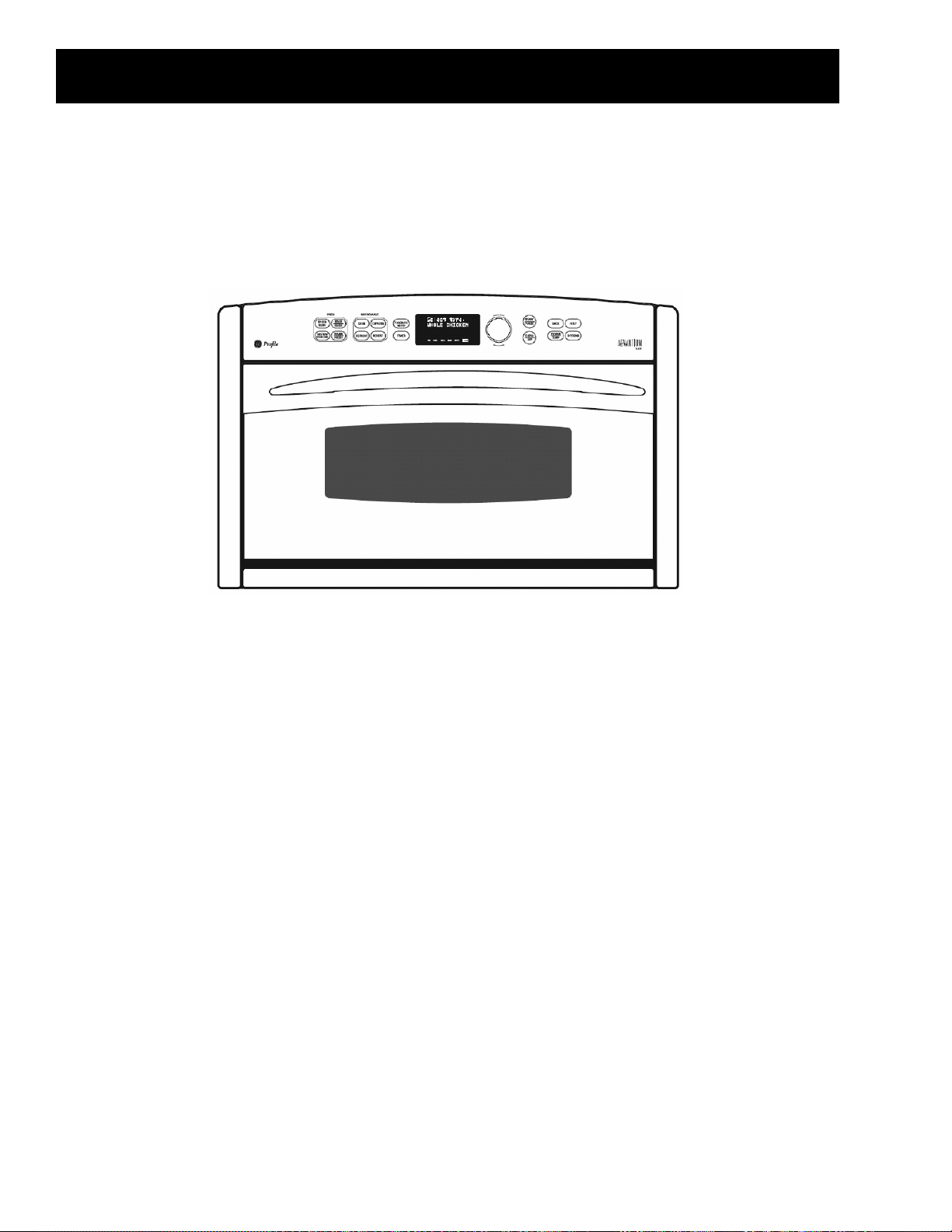
Control Features
With your Advantium oven, you can cook with high-intensity halogen lights, ceramic heaters and convection heating
element, and/or conventional microwave energy.
SPEEDCOOK/Repeat Last
Press this pad to access the pre-set
speedcook menu. Press and hold for
3 seconds to repeat the last cooking
selection.
BAKE/BROIL
Press this pad to bake, broil or toast.
CUSTOM SPEEDCOOK
Press this pad to set your own
speedcook program.
WARM/PROOF
Select WARM to keep hot, cooked
foods at serving temperature.
Select PROOF to set for a warm
environment useful for rising
yeast-leavened products.
COOK (Microwave)
Press this pad to microwave food that
is not in the FAVORITE RECIPES
section.
EXPRESS (Microwave)
Press for 30 seconds of microwave
cooking time. Each time the pad
is pressed adds an additional 30
seconds to the remaining cooking
time. The oven starts immediately.
DEFROST (Microwave)
Press this pad to defrost, soften or
melt frozen foods.
REHEAT (Microwave)
Press this pad to reheat servings of
previously cooked foods or a plate of
leftovers.
FAVORITE RECIPES
Press this pad to add, edit (change)
or remove a recipe from the memory.
TIMER
Press this pad to set the minute
timer.
Display
Shows and instructs the use of all
features on the oven.
SELECTOR DIAL–Turn to select, Press
to enter First turn, then press the dial
to make option, food power level or
temperature selections. Also use the
dial to increase (turn clockwise) or
decrease (turn counterclockwise)
cooking times.
START/PAUSE
Press this pad to start or pause any
cooking function.
CLEAR/OFF
Press this pad to cancel ALL oven
programs except the clock and timer.
BACK
Press this pad to step back one or
more levels in the program process,
such as when entering custom
recipes.
HELP
Press this pad to find out more about
your oven’s features.
POWER/TEMP
During cooking, press this pad
and turn/press the selector dial
to change the microwave power
level, the convection bake
temperature or the speedcook
temperature by adjusting the upper
and lower lamp and heater settings.
OPTIONS
Press this pad to set the Clock
and access the Beeper Volume, Clock
Display ON/OFF, Display Scroll Speed,
Delay Start and Reminder features.
O
S
T
E
N
L
E
R
C
U
T
T
P
R
E
S
S
T
START
PAUSE
CLEAR
OFF
R
E
T
N
E
O
LOCK/UNLOCK
HOLD 5 SECONDS
BACK
POWER
TEMP
HELP
OPTIONS
SPEED
COOK
CUSTOM
SPEED COOK
OVEN
BAKE
BROIL
WARM
PROOF
MICROWAVE
COOK
DEFROST
EXPRESS
REHEAT
FAVORITE
RECIPES
TIMER
FAN MSG REM MUTE TIMER
(Continued Next Page)
– 8 –
Page 9
Cooking Times
■ When speedcooking preprogrammed
foods, you may see OPTIMIZING COOK
TIME in the display several seconds after
you press START/PAUSE. The oven
automatically senses the electrical
voltage level in your home and
adjusts the cooking time up or
down for proper cooking.
Fan/Vent
■ The fan will be on during cooking. At
the end of cooking, the automatic fan
may continue to run for a short time, and
the display will read Oven is Cooling. The
fan will automatically shut off when the
internal parts of the oven have cooled.
■ The oven vent will emit warm air while
the oven is on.
Lights
■ When the oven is on, light may be visible
around the door or outer case.
■ The halogen lights will dim and cycle
on and off during a speedcook cycle,
sometimes even at full power levels.
This is normal. The oven senses the
heat level and adjusts automatically.
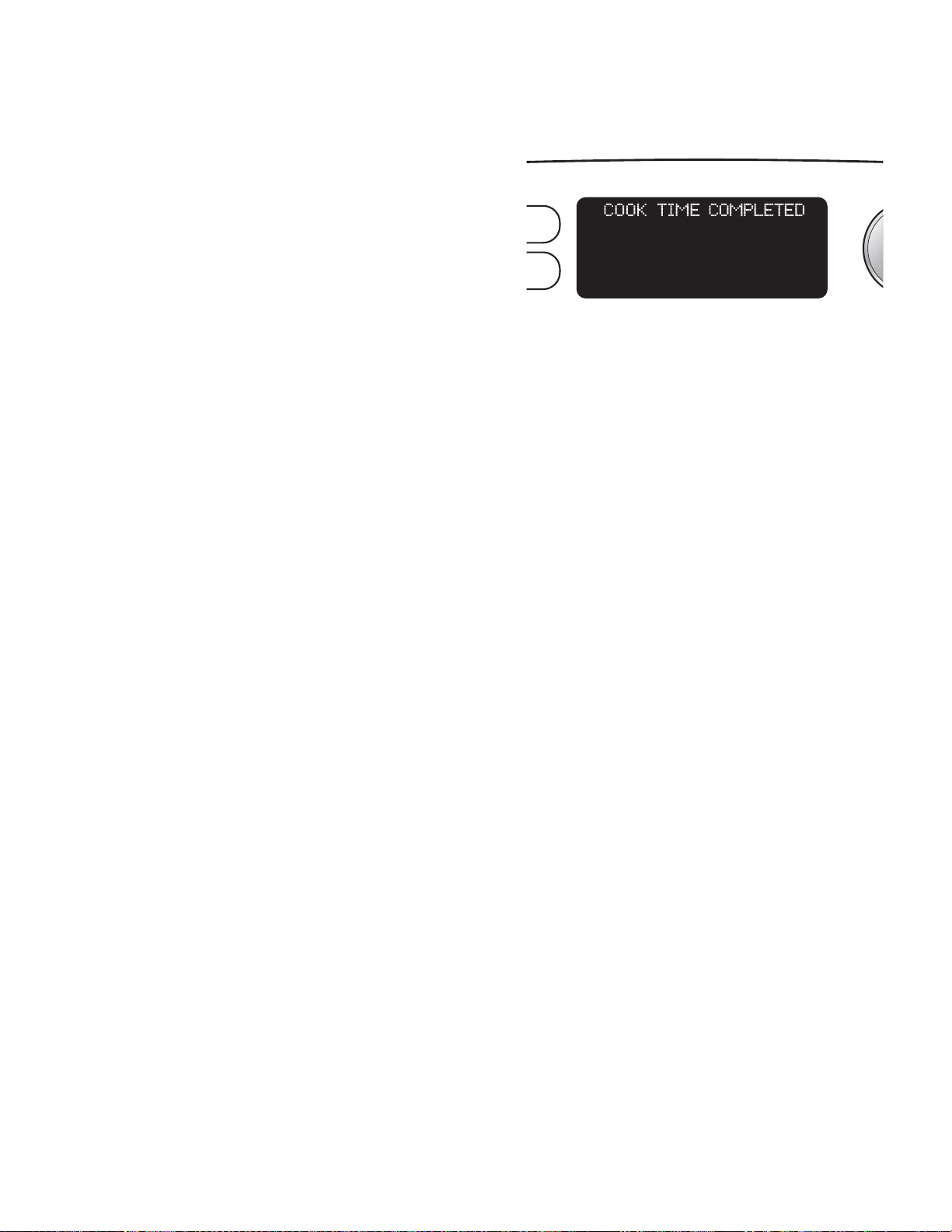
To remind you that you have food in the oven, the
Oven Heat
■ No preheating time is required during
Speedcook cycles. The oven begins
cooking immediately.
■ The door and inside of the oven will be
very hot. Use caution when opening the
door and removing food.
■ Do not use cookware or coverings made
of paper, plastic, or foil when cooking
during a speedcook cycle.
■ When cooking for an extended period
of time, the oven may automatically
reduce the power levels to maintain
the appropriate level of oven heat.
Sounds
■ Clicks and a fan blowing are normal
sounds during cooking. The relay board
is turning components on and off.
oven will display COOK TIME COMPLETED and beep
once a minute until you either open the oven door
or press the CLEAR/OFF pad.
RITE
IPES
ER
FAN MSG REM MUTE TIMER
* This occurs during speed cook only when the
cavity temperature approaches 425°F.
*
– 9 –
Page 10
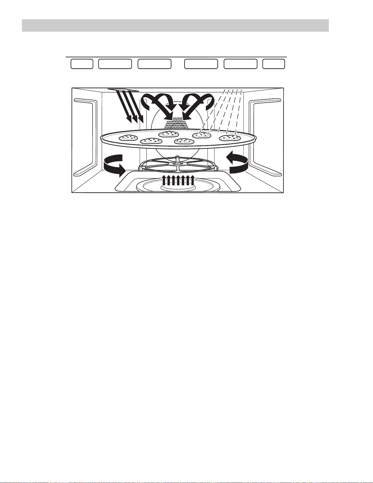
Speed Cook System
Halogen Lamp and Ceramic Heaters
One 500 watt halogen bulb and one 700 watt ceramic heater cook food from above.
•
One 375 watt ceramic heater cooks food from below.
•
Rear Convection Heat Element
Operates when using bake.
•
Microwave
A microwave “boost” is automatically added with certain foods.
•
The oven can also be used as a 975 watt microwave oven
•
– 10 –
(Continued Next Page)
Page 11

Speedcook Power Levels
Lower Heater
Advantium uses power from a high-intensity
halogen light, ceramic heaters, and microwaves
to cook food from the top, bottom, and interior
simultaneously, sealing in moisture and fl avor.
When using preset Speedcook recipes on the food
menu, power levels are preselected. However, these
power levels can be adjusted before or during
cooking. Also, the manual cook feature allows you
to speed cook items not on the preset food menu
by selecting your own cook time and power level
settings.
Each power level alternates heater power and
microwave energy throughout the cook time.
Percentage times of each power source vary,
dependant upon which power level has been
selected. The halogen light and ceramic heaters will
cycle on and off during a speedcook cycle, even
when full power has been selected.
UPPER POWER (U) controls both the upper heating
assembly and microwave power. A higher UPPER
POWER setting will utilize more upper heater power,
browning food faster on top. A lower UPPER POWER
setting utilizes more microwave power, causing food
to cook more evenly throughout. Select a higher
setting for such foods as pizza and baked goods.
Select a lower setting for foods such as casseroles,
meats, and fi sh.
LOWER POWER (L) controls the lower heater. Select a
higher setting to brown foods more on the bottom.
Select a lower setting for less browning on the
bottom.
Refer to the Speedcook Power Level Chart in
this chapter for specifi c power source operating
percentages.
Upper Heaters
The upper heating assembly consists of a 500 watt
halogen heater and a 700 watt ceramic heater. The
halogen and ceramic heaters provide radiant heat,
which browns the outside of the food while sealing
in moisture and fl avor. These heaters only operate in
the speedcook mode and always cycle on and cycle
off at the same time.
The lower heater is a 375 watt ceramic heater.
It operates in speedcook, oven/bake, and warm
modes. The lower heater assists in browning foods
on the bottom.
Microwave Energy
Caution: When cooking in Microwave mode, always
use the glass tray.
The Advantium 120 provides 975 watts of
microwave power, which is delivered directly
into the oven cavity to work independently, or in
conjunction with other cooking cycles. As the food
rotates on the oven turntable, microwave energy is
evenly distributed to all portions of the food.
Sensor Cooking
Advantium’s Microwave mode features sensor
cooking, which automatically selects cook times
and power levels. A humidity sensor detects the
increasing humidity released during cooking, senses
when the food is done, and shuts the oven off at the
appropriate time. Sensor cooking is not available for
5 minutes immediately following Speedcook.
Voltage Compensation
Note: Voltage compensation only occurs when
using a preselected menu item in Speedcook. These
items require compensation for accurate and
consistent cooking results.
Voltage fl uctuations in the power supply can cause
inconsistencies in cooking. The main PCB measures
line voltage at the start of each Speedcooking
selection and adjusts the cooking time to achieve
consistent results. Optimal line voltage, where no
voltage compensation occurs, is 120 VAC. Above
120 VAC, time is subtracted from the recipe. Below
120 VAC, time is added to the recipe. The amount of
voltage compensation required is dependent upon
the incoming voltage at the start of the cooking
cycle and the particular speedcooking selection that
is chosen.
The convection heater, located at the rear of the
oven, operates when using bake mode.
(Continued Next Page)
– 11 –
Page 12
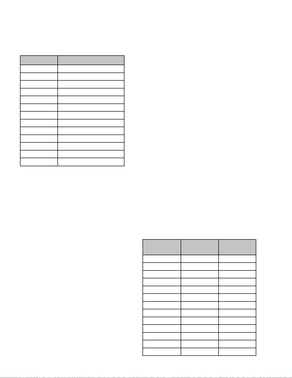
The following chart shows the predicted
compensation times based on a 12-minute
speedcook selection (such as Biscuits, Refr; Large).
Voltage Compensation Chart
Thermal Compensation
Note: Thermal compensation only occurs when
using a preselect menu item in Speedcook. These
items require compensation for accurate and
consistent cooking results.
Voltage Time Change (Seconds)
108 +180
110 +150
112 +120
114 +90
116 +60
118 +30
120 0
122 -21
124 -42
126 -63
128 -84
130 -105
132 -126
Note: Voltage compensation should be within 20
seconds of values in table.
Voltage compensation occurs after approximately 5
seconds of cooking operation. The display will show
OPTIMIZING COOK TIME. The time will fl ash and
then display the new adjusted time, based on the
amount of voltage compensation required.
When cooking several food items consecutively, the
temperature in the oven may become very high.
When Speedcooking, the Advantium automatically
compensates for the increased temperature by
reducing the amount of time the upper and lower
heaters are on during each 32-second duty cycle.
At the start of each new Speedcooking operation,
the cavity thermistor reads the oven temperature
and sends this information to the main PCB board.
If the oven temperature is 150°F or higher, the
main PCB board will initiate thermal compensation.
Thermal compensation will reduce the amount of
time the heaters are on in each 32-second duty
cycle. The reduction in heater time is based on the
oven temperature at the start of Speedcook. The
higher the initial cavity temperature, the less time
the heaters will be on per duty cycle.
Thermal compensation occurs only once, at the
beginning of a Speedcook cycle. In the following
thermal compensation chart, the fi rst column lists
the initial cavity temperature, the second and third
columns list the number of minutes and seconds the
unit will have thermal compensation active.
Thermal Compensation Chart
Voltage compensation only occurs during
Speedcook operation and only occurs once during
the cooking cycle (at initial start of Speedcook
operation).
Thermal Protection
Thermal protection is a safety feature built into the
Advantium’s software. In the event that the internal
oven temperature reaches 500°F, the thermistor will
communicate this information to the main PCB and
thermal protection will be initiated. While in thermal
protection mode, cooking cycles will be maintained;
however, heaters will not be utilized until the oven
reaches the proper operating temperature.
– 12 –
Initial Cavity
Temperature
150°F 2 7
175°F 2 33
200°F 3 0
225°F 3 27
250°F 3 53
275°F 4 20
300°F 4 47
325°F 5 13
350°F 5 40
375°F 6 7
400°F 6 33
425°F 7 0
450°F 7 27
Compensation
Time Minutes
(Continued Next Page)
Compensation
Time Seconds
Page 13

Speedcook Power Level Chart
Upper Power
Level
Hi
Medium Hi
Med
Lower Power
Level
Hi 100% 100% 0%
Lo 100% 80% 0%
Hi 100% 70% 0%
Lo 100% 65% 0%
Hi 90% 90% 10%
Lo 90% 65% 10%
Hi 80% 70% 20%
Upper Heater
On Time
Lower Heater
On Time
Microwave On
Time
Med Lo
Lo
Lo 70% 70% 30%
Hi 60% 60% 40%
Lo 30% 30% 70%
– 13 –
Page 14
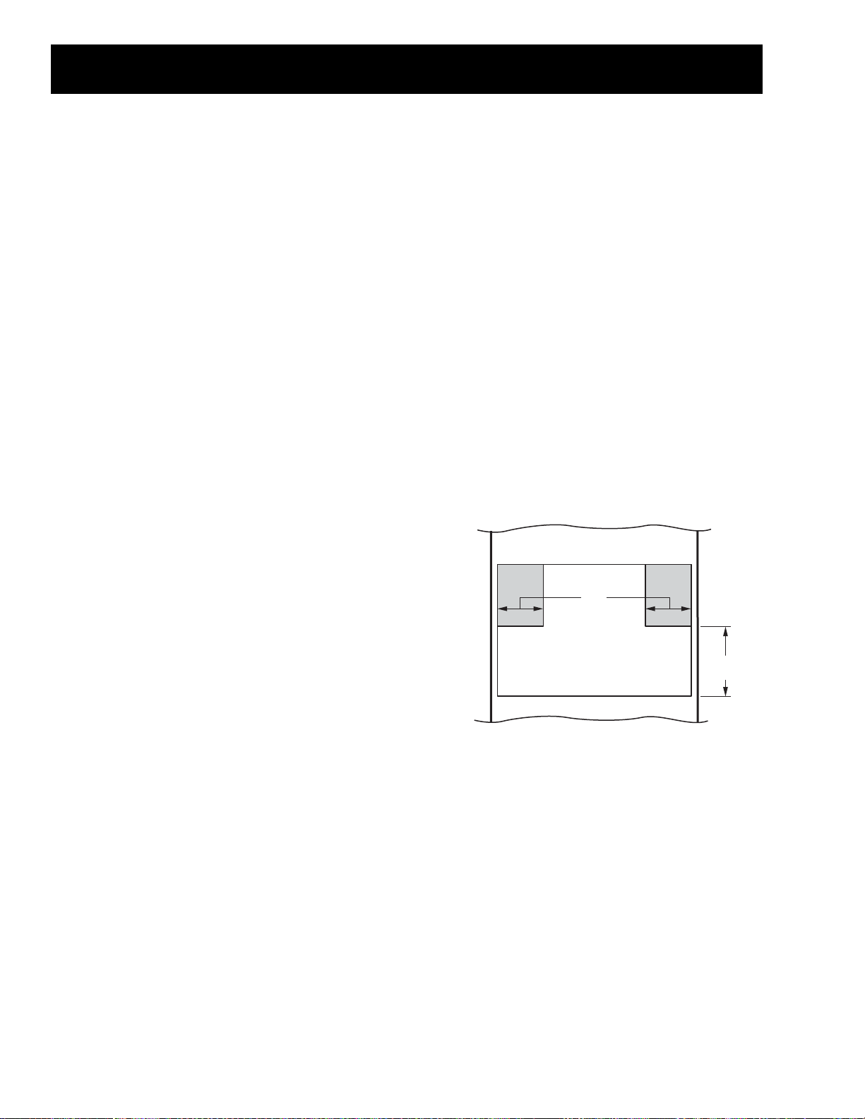
Installation
Locate outlet box in the shaded area
6”
9”
Advance Planning
These ovens may be installed directly into a 27-
•
in. or 30-in. wide oven cabinet.
The front surface of the oven will be nearly fl ush
•
with surrounding cabinet doors.
This oven can be installed over any GE or
•
Monogram single electric built-in oven, or a
warming drawer or both.
Color matched side trim pieces are provided
•
for installation into a 30-in. wide space. Use the
side trim when installing the oven above a 30”
wide wall oven or warming drawer. Discard the
side trim pieces if you are installing over a 27-in.
wide oven.
Cutout dimensions are the same for both 27-in.
•
or 30-in. wide cabinet installations.
IMPORTANT: This oven is not approved for use
above another built-in Speedcook oven, a side by
side installation or below a countertop.
Electrical Requirements
Single Advantium 120 Installation
This product requires a 120 volt, 60 Hz, 15 amp
circuit and draws 1.8 kilowatts. This product must be
connected to a supply circuit of the proper voltage
and frequency.
Wire size must conform to the requirements of
•
the National Electrical Code or the prevailing
local code for this kilowatt rating.
The power supply cord and plug should be
•
brought to a separate 15 or 20 ampere branch
circuit single grounded receptacle. The outlet
box should be located within reach of the 48-in.
power cord.
Electrical Location
For personal safety, this oven cannot be
•
installed in a cabinet arrangement such as an
island or peninsula.
The oven must be installed at least 36 3/4 in.
•
above the fl oor.
Allow for clearance to adjacent corners, walls,
•
drawers, etc.
Cabinets installed adjacent to wall ovens
•
must have an adhesion spec of at least 194ºF
temperature rating.
The oven must be securely installed in a cabinet
•
that is fi rmly attached to the house structure.
Weight on the oven door could cause the oven
to tip and result in injury. Never allow anyone to
climb, sit, stand or hang on the oven door.
IMPORTANT: (Please read carefully). The power cord
of this appliance is equipped with a three-prong
(grounding) plug that mates with a standard threeprong grounding wall receptacle to minimize the
possibility of electric shock. The customer should
have the wall receptacle and circuit checked by a
qualifi ed electrician to make sure the receptacle is
properly grounded and has the correct polarity.
Where a standard two-prong wall receptacle is
encountered, it is the personal responsibility and
obligation of the customer to have it replaced with
a properly grounded three-prong wall receptacle.
Do not, under any circumstances, cut or remove the
third (ground) prong from the power cord. DO NOT
USE AN EXTENSION CORD.
– 14 –
Page 15

Front View
Control Panel Assembly
Component Locator Views
Convection Fan Assembly
Turntable
Main Component Locator View
Blower Motor
Capacitor
Power
Transformer
Convection Heater
Assembly
Damper
Assembly
Thermistor
Magnetron
Fuse and Noise Filter
– 15 –
(Continued Next Page)
Page 16

Top View
High Voltage Transformer
Upper Heater Assembly
Upper Heater TCO
Bottom View
Low Voltage Transformer
Power Board
Capacitor
Diode
Blower Assembly
Relay Board
Damper Assembly
Magnetron
Fuse
Turntable Motor
Lower Heater Assembly
– 16 –
(Continued Next Page)
Page 17

Left Side View
Control Panel Assembly
Low Voltage Transformer
Humidity Sensor
Oven Cavity TCO
Right Side View
Lower Heater Assembly
Control Panel Assembly
Blower Assembly
Right Side Door Switch Assembly
Fuse
Noise Filter
– 17 –
(Continued Next Page)
Page 18

Control Panel Assembly (Shown separated)
Control Panel
Selector Board
Display Board
Control Board
Control Panel Bracket
Relay Board
Power Board
Low Voltage Transformer
– 18 –
Page 19

Power Board
Control Boards and Panel Connections
CN5 CN8 CN6
CN11
CN4
CN4 - Control Board
CN5 - Humidity Sensor
CN6 - Door Secondary Sensing Switch and Damper Door Sensing Switch
CN7 - Low Voltage Transformer (Secondary Windings)
CN7
CN8 - Thermistor
CN11 - Relay Board
– 19 –
(Continued next page)
Page 20

Relay Board
RY2
RY9
RY8
RY7
RY11
CN3
CN1 - Low Voltage Transformer (Primary Winding)
CN2 - Connection to Door Switch, Heater, and Turntable Motor
CN3 - Control Board
RY2 - High Voltage Transformer
RY7 - Convection Heater
RY8 - Upper Heater (Ceramic)
RY9 - Lower Heater
RY11 - Upper Heater (Halogen)
CN2
CN1
Control Board
CN3 - Relay Board
CN4 - Power Board
CN9 - Selector Board
CN13
CN10
CN9 CN4
CN3
CN10 - Display Board 20-Pin Connector
CN13 - Selector Board
(Continued next page)
– 20 –
Page 21

Display Board
20-Pin
Connector
to CN10
on Control
Board
Selector Board
CN14
CN13
CN9 - Control Board
CN13 - Control Board
CN14 - Control Panel
Control Panel
CN14 to
Selector
Board
CN9
– 21 –
Page 22

Component Access Chart
WARNING:
The oven is heavy and requires two
•
people to remove from the cabinet or
wall opening. Care should be taken when
removing and installing.
Sharp edges may be exposed when
•
servicing. Use caution to avoid injury.
Wear Kevlar gloves or equivalent
protection.
Blower Assembly
Capacitor and Diode
Components
Serviceability - Unit Partially Removed
Serviceability - Unit Installed
Serviceability - Unit Removed
Cavity Light
Cavity TCO
Control Panel Assembly
Convection Fan Motor
Convection Heater Assembly
Damper Assembly
Door
Door Assembly
Fuse
High Voltage Transformer
Humidity Sensor
Left and Right Door Switch Assemblies
Lower Heater Assembly
Low Voltage Transformer
Magnetron and Magnetron Thermostat
Noise Filter
Thermistor
Turntable Motor
Turntable Support
Upper Heater Assembly
Upper Heater TCO
– 22 –
Page 23

Oven Removal / Partial Removal
To remove the oven from cabinet or wall opening:
WARNING: This oven requires 2 people for complete
oven removal. Grasp the bottom of the oven at the
front and rear on each side.
Caution: Do not use the oven handle to lift or lower
the oven. Damage will occur.
Open the door and remove the wire rack,
1.
aluminum baking sheet, glass tray, metal tray,
and turntable.
Remove 4 screws from the side trims
2.
Slide the oven forward approximately 11 inches
3.
to access some components, or remove it
completely from the cabinet or wall opening.
Access Cover
To remove the access cover, the oven must be at
least partially removed from the installation.
The access cover is attached to the outer cover by 2
Phillips-head screws.
Outer Cover
To remove the outer cover, the oven must be
removed from the installation.
The outer cover is held in place by 21 Phillips-head
screws.
Unplug the power cord, and lower the oven onto
4.
a protected surface.
– 23 –
Page 24

Door Assembly
WARNING: A microwave leakage test must be
performed any time a door is removed, replaced, or
adjusted for any reason. (See Diagnostic and Service
Information
Door Removal
Caution: Do not close the door beyond the door
removal position. Damage to the inner door panel
will occur.
To remove the door, open the door fully and insert a
door removal tool (Part # WB01X10318) in each door
hinge opening. The door can then be slowly closed
a few inches to the door-removal position and lifted
from the oven.
.)
To disassemble the door:
Remove the 4 screws from the glass mount.
1.
Remove the choke cover.
2.
Remove the 4 screws from the door frame, and
3.
remove door frame from the glass supporter.
Remove the 4 screws from the glass supporter,
4.
and remove the door handle and vent trim from
the glass supporter.
SCB1000K and SCB1001K
Latch
Latch
Spring
Glass
Supporter
Choke Cover
Tool
Door Hinge Opening
Door-Removal Position
Tool
Door
Handle
Glass Mount
Latch
Spring
Door
Handle
Door
Frame
Door Glass
Door Deco
ZSC1000K and ZSC1001K
Latch
Door
Frame
Latch
Spring
Choke Cover
Latch
Spring
– 24 –
Door Glass
Door Panel
Page 25

Control Panel Assembly
The control panel assembly consists of an outer
control panel and an inner control panel bracket.
The outer control panel contains the control, display,
and selector circuit boards. The power and relay
circuit boards, and the low voltage transformer are
attached to the control panel bracket. Removing the
control panel allows access to the oven lamp.
The control panel is held in place with 7 Phillipshead screws and 4 tabs. Two of the screws are
recessed from the top of the outer cover. Access
holes are provided. A magnetic screwdriver is
necessary to capture these screws.
To remove the control panel assembly:
Place the oven in a partially removed position.
1.
(See Oven Removal / Partial Removal.)
Remove the 3 Phillips-head screws from the top
2.
front of the outer cover.
4. Remove the 2 Phillips-head screws that attach
the control panel assembly to the side of the
frame.
5. Open the oven door.
Grasp the bottom of the control panel assembly
6.
and lift to release the 4 tabs that hold the
bottom of the control panel assembly to the
oven frame.
3. Remove the 2 recessed Phillips-head screws
that attach the control panel assembly to the
top of the frame.
Disconnect wire harnesses from the power
7.
board at locations CN5, CN6, and CN8.
Disconnect wire harnesses from the relay board
8.
at locations RY2, RY7, RY8, RY9, RY11, and CN2.
– 25 –
(Continued Next Page)
Page 26

To remove the power board:
Remove the control panel assembly. (See Control
1.
Panel Assembly.)
Disconnect wire harnesses from the power
2.
board at locations CN4, CN7, and CN11.
Remove the 4 Phillips-head screws that attach
3.
the power board to the control panel bracket.
Lift the power board to clear the retaining tab.
4.
Tab
CN7
CN11
CN4
To remove the relay board:
Remove the control panel. (See Control Panel
1.
Assembly.)
Peel back the foam tape.
2.
Disconnect the wire harness from the power
3.
board at location CN11 and release the harness
from the wire retainer.
Disconnect wire harnesses from the relay board
4.
at locations CN1 and CN3.
Remove the 5 Phillips-head screws that attach
5.
the relay board to the control panel bracket.
Lift the relay board to clear the retaining tab.
6.
Wire Retainer
CN11
CN3
Foam Tape
Tab
CN1
– 26 –
(Continued Next Page)
Page 27

To remove the control panel bracket:
1.
Remove the control panel. (See
Assembly.)
Disconnect wire harnesses from the relay board
2.
Control Panel
at location CN3 and from the power board at
location CN4.
Peel back the foam tape and release the wire
3.
harness to CN4 from the wire retainer.
Remove the 4 Phillips-head screws (2 on each
4.
side) from the control panel bracket.
Slide the control panel bracket to the right then
5.
lift the control panel bracket from the control
panel.
Guide the disconnected harnesses through the
6.
wire entry hole in the control panel bracket.
To remove the control board:
Remove the control panel bracket. (See Control
1.
Panel Assembly.)
Disconnect the 20-pin harness connector from
2.
the display board.
Disconnect the wire harnesses from the selector
3.
board at locations CN9 and CN13.
Remove the 4 Phillips-head screws that hold the
4.
control board to the control panel.
Wire Retainer
Wire Entry Hole
Foam Tape
To remove the display board:
The display board is attached to the control panel
by 2 Phillips-head screws and positioned by 2 pins.
The display board connects to the control board
with a 20-pin wire harness. To access the display
board it is necessary to remove the control panel
bracket. (See Control Panel Assembly.)
Pin
20-Pin Wire Harness
Pin
– 27 –
(Continued Next Page)
Page 28

To remove the selector board:
Remove the control panel bracket. (See Control
1.
Panel Assembly.)
Pull the dial straight out from the control panel.
2.
Disconnect wire harnesses from the selector
3.
board at locations CN9 and CN13.
Low Voltage Transformer
The low voltage transformer is held in place by 2
Phillips-head screws.
The control panel must be removed to access
the low voltage transformer. (See Control Panel
Assembly.)
Disconnect the wire harness from the control
4.
panel at location CN14.
Remove the 6 Phillips-head screws that attach
5.
the selector board to the control panel.
CN13
CN9
To remove the control panel:
To access the control panel it is necessary to remove
the control panel bracket, control, display, and
selector boards. (See Control Panel Assembly.)
The low voltage transformer is connected to the
power board at location CN7 and on the relay board
at location CN1.
Resistance Check
1.
Disconnect the harness from the relay board at
location CN1.
2.
Check the primary winding for approximate
resistance value between the white and black
wires of 23.2 Ω.
3.
Disconnect the harness from the power board
at location CN7.
4.
Check the secondary windings for approximate
resistance value between:
•
Yellow to black - 1.5 Ω
•
Black to white - 5.2 Ω
•
Red to brown - 1.1 Ω
Note: Voltage check for the transformer is:
•
Yellow to black - 13 VAC
•
Black to white - 20 VAC
•
Red to brown - 8 VAC
– 28 –
Page 29

Cavity Light
Fuse
The oven lamp is inserted in a socket that is
attached to the lamp housing with 2 Phillips-head
screws. The screws are recessed from the top of the
outer cover. Access holes are provided. A magnetic
screwdriver is necessary to capture these screws.
It is necessary to remove the control panel to access
the oven lamp. (See Control Panel Assembly.)
The oven cavity light will come on during a
microwave cooking cycle.
Important Note: The primary interlock, monitor
interlock, door sensing (secondary interlock)
switches, and the relay board must all be replaced
when the 20 amp fuse opens due to operation of the
monitor interlock switch.
The unit is equipped with a 20 amp fuse (Part #
WB27X10388).
The fuse is located in a receptacle near the top of
the noise fi lter and is common to all functions and
door switches.
Fuse
Caution: Do not twist the lamp.
The oven lamp is a 130-VAC, 20-watt lamp (Part #
WB08X10050). It is a plug-in type lamp.
Note: If the fuse opens, it will disable all oven
functions including the display. The oven must be
partially removed to access the fuse. (See Oven
Removal / Partial Removal.)
– 29 –
Page 30

Noise Filter
Capacitor and Diode
The noise fi lter is located behind the blower
assembly on the right side of the oven. The noise
fi lter is held in place by a single Phillips-head screw.
The fi lter ground wire is attached to the oven
chassis near the noise fi lter by a single Phillips-head
screw. The outer cover must be removed to access
the noise fi lter. (See
Oven Removal / Partial Removal.)
Note: When installing the noise fi lter, ensure all fi lter
wiring is connected to the correct terminals.
Top View of Noise Filter
Ground Wire Screw
Screw
WARNING: Always be certain the capacitor is
discharged before servicing. Mechanically discharge
by placing an insulated handle screwdriver between
the diode connection of the capacitor and the oven
chassis ground.
Note: The capacitor has an internal discharge
resistor that automatically discharges the capacitor
when the oven turns OFF. Under normal operation,
capacitor should fully discharge within 30 seconds.
The oven must be
partially removed to
Diode
access the capacitor. (See
Oven Removal / Partial
Removal.) The capacitor
Screw
is located behind the top
access cover and is held
in place by 2 Phillips-head
screws. A single Phillipshead screw attaches the
capacitor and diode to
the oven chassis.
Noise Filter
Check to make sure the fuse is good. Check the
noise fi lter for approximate resistance value at the
following locations:
White (neutral input) to white (neutral output) - 0 Ω
Black (line input) to black/brown (line output) - 0 Ω
White (neutral input) to black (line input) - 23 Ω
Front View of Noise Filter
Input
Wire
Harness
Note: When disconnecting the wires and diode from
the capacitor, note wire and diode locations.
The capacitor wires have locking tabs. Remove
the capacitor, capacitor bracket, and diode as one
assembly.
Output-N
Output-L
– 30 –
Page 31

Magnetron and Magnetron TCO
High Voltage Transformer
WARNING: Always be certain the capacitor is
discharged before servicing. (See Capacitor and
Diode.) Mechanically discharge by placing an
insulated handle screwdriver between the diode
connection of the capacitor and the oven chassis
ground.
Note: The capacitor has an internal discharge
resistor that automatically discharges the capacitor
when the oven turns OFF. Under normal operation,
the capacitor should fully discharge within 30
seconds.
The oven must be removed to access the
magnetron. (See Oven Removal / Partial Removal.)
The magnetron is located behind the top access
cover. The top access cover is held in place by 2
Phillips-head screws. The magnetron is held in
place by 4 Phillips-head screws. The magnetron
thermostat must be disconnected before removing
the magnetron.
WARNING: Always be certain the capacitor is
discharged before servicing. (See Capacitor and
Diode.) Mechanically discharge by placing an
insulated handle screwdriver between the diode
connection of the capacitor and the oven chassis
ground.
Note: The capacitor has an internal discharge
resistor that automatically discharges the capacitor
when the oven turns OFF. Under normal operation,
the capacitor should fully discharge within 30
seconds.
The oven must be removed to access the high
voltage transformer. (See Oven Removal / Partial
Removal.) The high voltage transformer is located
behind the top access cover. The top access cover is
held in place by 2 Phillips-head screws.
The transformer is held in place with 4 Phillips-head
screws. Two of the screws are recessed from the
top of the outer cover. Access holes are provided. A
magnetic screwdriver is necessary to capture these
screws.
Magnetron
Magnetron TCO
Magnetron TCO
The magnetron TCO is attached to a bracket
mounted to the magnetron. The magnetron bracket
is held in place by a single Phillips-head screw.
This position of the magnetron TCO allows it to
sense the temperature of the magnetron.
The magnetron TCO opens at 302°F and cannot be
reset. If the magnetron TCO opens, it will disable all
oven functions including the display.
Transformer
When disconnecting the primary and secondary
wire connections, note the wire locations. The wire
connectors use releasing locking tabs.
ELECTRICAL TERMINAL
RELEASE/LOCKING TAB
Check the high voltage transformer windings for
approximate resistance value between:
Red to white (primary) - .5 Ω
Red/Black to chassis ground (secondary) - 87 Ω
Magnetron harness (fi lament high voltage) - .2 Ω
– 31 –
Page 32

Damper Assembly
Blower Assembly
The damper assembly is on the top right side of
the oven cavity. When the damper door is closed,
moisture is retained in the oven cavity. When the
damper door is open, moisture is released, allowing
food to be more crisp.
The outer cover must be removed to access or
observe operation of the damper assembly. (See
Oven Removal / Partial Removal.)
The damper assembly is held in place by 2 pins
and 3 Phillips-head screws that attach the damper
assembly to the oven chassis. When removing,
move the damper assembly inward to disengage
the 2 pins from the vent tube.
Pin
Pin
A blower protects the oven from too much heat
inside the oven cavity. It automatically turns on at
low speed if it senses too much heat. The blower will
automatically turn off when the internal parts are
cool. It may stay on for 30 minutes or more after the
oven control is turned off.
The blower motor has an approximate resistance
value of 14 Ω.
Blower Assembly
Damper Door Switch
The damper door sensing switch is mounted to the
damper assembly. The switch monitors the damper
door position and provides this information to the
main PCB, which controls the operation of the
damper
door motor.
When the
Damper Door Motor
damper
door is
closed, the
switch is
open. The
motor will
run until
Damper Door Switch
the switch
sends the door closed signal. If the damper door
sensing switch circuit shorts (or opens), the damper
motor will run continually. The damper motor has
an approximate resistance value of 3.36 K Ω.
To remove the blower assembly:
Remove the oven from cabinet or wall opening
1.
and remove the outer cover. (See Oven Removal /
Partial Removal.)
Disconnect the blower motor wiring and the
2.
oven lamp wire harness.
Lamp
Wire
Harness
Blower Motor Wires
Damper Door Operating Modes
Cooking
Mode
Damper
Position
Switch Plunger
Position
Switch
Contacts
Microwave Open Not Depressed Closed
Speedcook Closed Depressed Open
– 32 –
Remove the foam seal from the blower bracket.
3.
Remove wiring from the guides in the blower
4.
bracket and from the retainers on the blower
housing.
(Continued Next Page)
Page 33

Disconnect wire harnesses on the relay board at
5.
locations CN2, RY2. RY7, RY8, RY9, and RY11.
Disconnect
Remove the single Phillips-head screw that
6.
Disconnect
attaches the fi lter ground wire to the oven
chassis.
Remove the 5 Phillips-head screws that attach
7.
the blower bracket to the oven chassis.
Upper Heater and Oven Cavity TCOs
The TCOs automatically shut off the oven in the
event of excessive temperatures. When replacing,
be sure to determine the cause of failure. If a TCO
opens, it will disable all oven functions except
the oven light. The outer cover must be removed
to access the TCOs. (See Oven Removal / Partial
Removal.)
The upper heater TCO is mounted on the heat
•
shield above the upper heater assembly.
The oven cavity TCO is mounted to the exhaust
•
duct on the left side of the oven.
Both TCOs are held in place by a singe Phillips-
•
head screw.
Both TCOs open at 293°F and cannot be reset.
•
Upper Heater TCO
Ground Wire
Carefully lift the blower assembly from the oven
8.
chassis.
Remove the 6 Phillips-head screws that hold the
9.
blower housing to the bracket.
Oven Cavity TCO
Note: When installing the blower assembly, ensure
that the fi lter ground wire is secured to the oven
chassis.
– 33 –
Page 34

Upper Heater Assembly
The halogen heater has an approximate resistance
value of 1.8 to 3.7 Ω. It is connected using a white
wire harness.
The ceramic heater has an approximate resistance
value of 15 to 25 Ω. It is connected using a yellow
wire harness.
To remove the upper heater assembly:
Straighten the 4 folded lock tabs.
5.
Remove the 8 Phillips-head screws that attach
6.
the heater cover. Lift off the cover.
Caution: Mark each of the wire harnesses
before disconnecting. The connectors could be
interchanged, causing an adverse effect in cooking
performance.
Remove the oven from cabinet or wall opening
1.
and remove the outer cover. (See Oven Removal /
Partial Removal.)
Disconnect the heater assembly wire harnesses
2.
and pull them through the wire guide.
Disconnect wires from the upper heater TCO.
3.
Lock Tabs
Remove the 3 Phillips-head screws that attach
7.
the heater assembly to the oven chassis.
Remove the 2 Phillips-head screws, wire retainer,
4.
and the heater shield from the heater assembly.
– 34 –
Carefully lift the heater assembly from the oven
8.
chassis.
Page 35

Lower Heater Assembly
Lower heater
Heater
bracket
Reflector
Base plate
Convection Heater Assembly and Thermistor
The lower ceramic heater has an approximate
resistance value of 32 to 42 Ω.
To remove the lower heater assembly:
Remove the oven from cabinet or wall opening.
1.
(See Oven Removal / Partial Removal.)
Remove the 2 Phillips-head screws from the
2.
bottom of each side of the outer cover.
Remove the 6 Phillips-head screws that attach
3.
the bottom to the oven.
The oven must be removed from the cabinet or wall
opening to access the convection heater assembly.
(See Oven Removal / Partial Removal.)
The convection heater assembly is composed of an
inner and outer fan blade, motor, heating element,
and thermistor.
Remove the rear cover. Three Phillips-head screws
hold the cover in place.
Thermistor
Thermistor
Disconnect the bottom heater and turntable
4.
wire harnesses.
Straighten the 4 folded tabs and remove the
5.
3 Phillips-head screws that hold the heater
assembly to the oven chassis.
Bottom View with Baseplate Removed
Tabs
The thermistor must be removed before removing
the convection heater assembly. The thermistor is
attached to the convection heater assembly by a
single Phillips-head screw.
The thermistor is connected to the power board
at location CN8. The approximate values at room
temperature are: Red - Blue = 400K Ω; Red - White
= 290K Ω; Blue - White = 110K Ω.
Convection Heater Assembly Shown with
Rear Cover Removed
Thermistor
(Continued Next Page)
– 35 –
Page 36

Convection Heater Element
Convection Fan Motor
The convection heater assembly is held in place
by two 7-mm hex-nuts and 4 Phillips-head screws
The convection heater element has an approximate
resistance value of 9.5 Ω. Two Phillips-head screws
connect the power wires to the element terminals.
The convection fan motor wire leads have locking
tabs that must be depressed to be disconnected.
To remove each wire from the fan motor, depress
the clip using a small blade screwdriver and pull the
wire off the terminal as shown.
ELECTRICAL TERMINAL
RELEASE/LOCKING TAB
The outer convection fan must be removed before
removing the motor. The outer convection fan is
held in place by a 7-mm nut, lockwasher, spacer
and fl at washer.
Front View of Outer Convection Fan
The convection heater
element is held in place
by 4 Phillips-head
screws. (Three screws on
the front, and 1 screw
on the end.)
The convection fan motor is held in place by 3
Phillips-head screws .
Rear View of Convection Fan
Convection Fan Motor
End View of Element
– 36 –
Page 37

Humidity Sensor
r
Turntable Motor
The humidity sensor is mounted to the exhaust duct
on the left side of the oven. The outer cover must be
removed to access the humidity sensor. (See Oven
Removal / Partial Removal.) The humidity sensor is
connected to the power board at location CN5. The
humidity sensor is held in place by 2 Phillips-head
screws.
The humidity sensor detects the increasing humidity
released during cooking. The oven automatically
adjusts the cooking time to various types and
amounts of food.
The turntable motor is held in place with 2 Phillipshead screws. To replace it requires removing the
turntable, turntable support, and the oven from the
cabinet or wall opening. (See Oven Removal / Partial
Removal.) A single Phillips-head screw attaches an
access panel to the bottom of the oven. A single
wire harness is connected to the turntable motor.
Note: When replacing the turntable support, ensure
it is fully seated into the "D" shaped shaft of the
turntable motor and is fl ush with the oven fl oor.
Humidity Sensor
Humidity Sensor Test
Note:
The oven should be plugged in at least 5
•
minutes before test.
Room temperature should not exceed 95°F.
•
Be sure the interior of the oven is dry.
•
No sensor cooking is available for 5 minutes
•
immediately after speedcook.
Access the control panel.
Disconnect the humidity sensor wire harness from
the power board at location CN5.
On the humidity sensor wire harness check for
approximate resistance values between:
The turntable motor has an approximate resistance
value of 2.6 K Ω.
Base plate cove
Wire leads
Turntable motor
Black-Red = 6.5 k Ω
•
Red-White = 3.25 k Ω
•
Black-White = 3.25 k Ω
•
– 37 –
Page 38

Monitor interlock
switch
Door sensing
(Secondary
Interlock)
Primary interlock
switch
Left and Right Door Switch Assemblies
The primary interlock, monitor interlock, and
door sensing (secondary interlock) switches are
mounted on plastic latch boards. The latch boards
are attached to the left and right side of the oven
cavity. The left side latch board contains the door
sensing (secondary interlock) switch. The right side
latch board contains the primary interlock and the
monitor interlock switches.
Remove the single Phillips-head screw that
2.
holds each door switch access cover to the
outer cover.
Remove the primary interlock and door sensing
3.
switch leads to isolate each switch.
Check continuity of each switch with door open
4.
and door closed. Normal readings are as follows:
• Door Closed: 0 Ω
• Door Open: Infi nity
How to Test the Monitor Switch:
Note: The right side latch pawl pushes horizontally
and actuates the lever of the monitor interlock,
opening the switch.
Disconnect power and partially remove the
1.
oven from it’s installation. (See
Partial Removal.)
Remove the single Phillips-head screw that
2.
Oven Removal /
holds the right side door switch access cover to
the outer cover.
Right side Latch Board Shown
Monitor Interlock Switch
Primary Interlock Switch
Remove the monitor switch leads to isolate the
3.
switch.
Check continuity of the switch with door open
4.
and door closed. Normal readings are as follows:
• Door Closed: Infi nity
• Door Open: 0 Ω
How to Test Interlock System:
1. Disconnect power, remove the outer cover (See
Oven Removal / Partial Removal) and discharge
capacitor.
2. Check 20 amp fuse for continuity and proper
size. Do not use any other fuse or size except 20
amp.
3. Remove monitor switch leads to isolate switch.
Check continuity of switch with door open and
door closed.
• Door Closed: Infi nity Ω
How to Test Primary Interlock and Door Sensing
Switches:
1.
Disconnect power and partially remove the
oven from it’s installation. (See
Partial Removal.)
Oven Removal /
• Door Open: 0 Ω
4. Reconnect switch wiring.
(Continued Next Page)
– 38 –
Page 39

5. Test Circuit Operation.
a. Connect temporary jumper leads across
relay contacts, primary interlock and door
sensing switches to simulate shorted switch
contacts. Locate convenient connections in
circuit to be certain COM and NO terminals
are used.
b. Connect ohmmeter (Rx1) across the line
terminals of the appliance cord. Continuity
must show the following:
• Door Closed : Some Ω
• Door Open : .3 Ω
c. Remove 20 amp fuse. Circuit must open
(infi nity
and interlock circuits.
WARNING: After test, remove temporary jumper
leads from interlock and relay.
WARNING: Primary interlock, door sensing switch,
monitor switch, and relay board must be replaced
when the 20 amp fuse is blown due to operation of
monitor switch.
Ω). If not, check wiring of monitor
To replace the door switches:
1.
Place the oven in a partially removed position.
Oven Removal / Partial Removal.)
(See
Open the oven door.
2.
Remove the single Phillips-head screw that
3.
holds the door switch access cover to the outer
cover.
Disconnect the switch wiring.
4.
Using a fl at blade screwdriver, carefully press
5.
the lock tab until fl ush with the surrounding
area of the latch board.
Using the mounting pin as a pivot, carefully
6.
rotate the switch past the lock tab and
Remove the switch from the mounting pin.
Rotate Switch
Note: Perform microwave leakage test when
replacing or adjusting interlock switches or latch
board.
How to Adjust the Interlocks:
The latch board is adjustable for proper door closure
and switch operation.
Disconnect power and partially remove the
1.
oven from it’s installation. (See Oven Removal /
Partial Removal.)
Note: Each latch board is held in place and adjusted
with 2 Phillips-head screws. The screws are recessed
from the top of the outer cover. Access holes are
provided.
2. Loosen the 2 Phillips-head screws that attach
the latch board to the oven chassis.
3. Adjust each latch-board for proper door closure
and switch operation, retighten screws.
Note: Perform microwave leakage test when
replacing or adjusting interlock switches or latch
boards.
Pivot Pin
Lock Tab
– 39 –
(Continued Next Page)
Page 40

To replace the latch boards:
Place the oven in a partially removed position.
1.
(See Oven Removal / Partial Removal.)
Open the oven door.
2.
Remove the single Phillips-head screw that
3.
holds the door switch access cover to the outer
cover.
Disconnect the switch wiring.
4.
Note: Each latch board is held in place with 2
Phillips-head screws. The screws are recessed
from the top of the outer cover. Access holes are
provided. A magnetic screwdriver is necessary to
capture these screws.
5. Remove the 2 Phillips-head screws that attach
the latch board to the oven chassis.
6. Remove the door switches from the latch board.
– 40 –
Page 41

Diagnostics and Service Information
USE ONLY HEAT AND MICROWAVE RESISTIVE GLASS BOWL
– 41 –
Page 42

Demo Mode
Standard Test Load
The Sales Demo mode will allow dealers to
demonstrate all oven functionality with one
exception: No power is ever applied to any of the
halogen lamps, heaters, mag HVT or inrush relays
while the control is in sales mode.
The sales mode will be initiated by holding the
“POWER / TEMP” and “START” pads down at the
same time for a full 3 seconds. This mode can only
be entered during the initial “SELECT TIME” display
that occurs when the unit powers up after a long
(>60 seconds) power outage. When sales mode
is initiated, a 2 short-beep signal is sounded and
all oven functions will operate with the following
exceptions;
1. No power shall ever be applied to any the
heaters, Halogen lamps, magnetron HVT or
Inrush control relays. The control relays for
any of these loads shall not be switched during
sales mode.
2. The DEMO icon will be lit whenever the unit is in
sales mode regardless of settings or the feature
being selected.
The standard test load is one liter (1000 ml) water
with starting temperature of 59°F ~ 75°F in a 1000
ml beaker. (DO NOT USE ANY OTHER LOAD OR DISH
AS RESULTS WILL VARY FROM STANDARD.)
PERFORMANCE TEST FOR MICROWAVE
Use Clear Glass Tray and the beaker.
1.
(Part # WB64x0073)
Record initial water temperature.
2.
Run at high power for 2:03.
3.
Record end water temperature. The minimum
4.
difference between the initial and ending
temperature should be: 32°F @ 120V.
Fault Codes
The smart board monitors various operations and
can detect certain failure modes. In the event of
specifi c failures, cooking will be terminated, a four
beep signal will be heard, and a fault code will be
displayed.
The sales mode is cleared by holding the “POWER
/ TEMP” and “START” pads down at same time for a
full 3 seconds. The sales mode can only be cleared
during the same initial “SELECT TIME” display that
occurs when the unit powers up after a long (>60
seconds) power outage. After 5 seconds elapse, all
functions of the oven will return to normal operation.
When power-up occurs, software will check the
special sales demo identifi er code. If the code is
set, then the oven will stay in the sales demo mode.
This will prevent the unit from powering back up to
a normal mode if power to the salesroom had gone
off .
Pressing the CLEAR pad will remove the fault code
display, unless the failure is a shorted keypanel
switch. Detection of a failed sensor will have no
effect on features that do not use that sensor.
F4 (open or shorted humidity sensor) and F6 (high
cavity temperature during microwave cooking)
codes apply only to microwave cooking. The
chart below indicates failure modes which can be
detected and displayed.
Display Failure Detected
F1 Oven cavity thermistor open
F2 Open cavity thermistor shorted
F3 Key panel shorted (> 60 seconds)
F4 Humidity sensor open or shorted
F6
High cavity temperature detected
during microwave oven cooking
– 42 –
Page 43

Microwave Leak Test Proof Feature
To test the performance of the proof feature, press
the WARM/PROOF pad, then turn the dial to PROOF
BREAD and press the dial to start. The following will
occur:
• The convection fan and interior lamp come on
immediately, and stay on.
• There is an immediate start-up burst (about 1.5
second duration at 75°F ambient) of heat from
the convection heater.
• The convection fan and interior lamp continue
Place 275 ml water in 600 ml beaker.
1.
(Part # WB64x5010)
Place beaker in center of Clear Glass Tray.
2.
Set meter to 2450 MHz scale.
3.
Turn “ON” for 5 minute test.
4.
to operate and, if needed, the convection heater
will cycle on.
Note: Oven proof temperatures range from 75-
95°F. At ambient temperatures above 75°F, heat
generated by the interior lamp may be suffi cient to
maintain proof temperatures, and the heater may
not cycle again after start-up.
Hold probe perpendicular to surface being
5.
tested. Scan surfaces at the rate of one inch per
second. Scan entire perimeter of door, control
panel, viewing surface of door window, and
exhaust vents.
Maximum leakage is 4 MW/CM2.
6.
Record data on service invoice and microwave
7.
leakage report.
Note:
Maximum allowable leakage is 5 MW/CM2. Four
•
MW/CM2 is used to allow for measurement and
meter accuracy.
Inform the manufacturer of any oven found to
•
have emission in excess of 5 MW/CM2. Make
repairs to bring the unit into compliance at
no cost to owner and try to determine cause.
Instruct owner not to use oven until it has been
brought into compliance.
If an inoperative convection heater in the proof
mode is suspected:
1. Disconnect power.
2. Remove the rear access cover.
3. Remove the thermistor from the convection
heater assembly.
4. Lower the thermistor temperature by placing a
chilled or frozen item against the thermistor.
5. Connect power and enter proof mode.
6. Check for approximately 120 VAC (12.3 Amps) at
the convection heater.
– 43 –
Page 44

Schematics and Wiring Diagrams
WARNING: POWER MUST BE DISCONNECTED BEFORE SERVICING THIS APPLIANCE
– 44 –
(Continued Next Page)
Page 45

W3
BK2
OVEN TCO
GROUND
HARNESS LEADS
PARTS LEADS
R1
R7
BK6
BL3
BN3
BN3
GN1
C11
BK
WR
CN11
R6
LVT
W
YLBK W R BN
BK
HUMIDITY
SENSOR
PK1
W4
W2
R4
BL2
YL1
W4
W9
W6
MGT
RY2
RELAY PCB POWER PCB
L-H
RY9
MAIN
CN2
CN1
1713
13
CN7
11
13
5
SENSOR
CN5
THERMISTOR
CN8
13
DOOR
CN6
3
CONV
RY7
U-H(C)
RY8
U-H(H)
RY11
YL3
THERMISTOR
SECONDARY
SENSING S/W
D.MOTOR
SENSING S/W
D.MOTOR
SENSING
SWITCH
P/CORD
NOISE
FILTER
BK5
YL4
PK2
W8
BK2
BK
GN
GN
W
W1
BN4
YL4
W8
BK1
BK9
R10
W9
W10
HTR TCO
R1
BN4
OVEN
LAMP
BL3
W2
YL3
W1
MGT
TCO
W5
BL2
UPPER HEATER
(CERAMIC)
YL2
BL5
BN3
R5
BK3
BL5
UPPER HEATER
(HALOGEN)
BLOWER
MOTOR
R7
YL2
R3
MONITOR
SWITCH
CONVECTION
MOTOR
CONVECTION
SHEATH
HEATER
DAMPER
MOTOR
CROUND
H.V. DIODE
HVC
W
R
5
3
4
12
MGT TUBE
FA F
PRIMARY
INTERLOCK
SWITCH
R2
BN1
BK6
BK1
LOWER CERAMIC
HEATER
TURNTABLE
MOTOR
PK1
BL1BL
BK
YL
BL
R
1
4
BL1
BK3
R4
GN1
R5
W
R6
BN2
BN1
BN2
BK4
BK4
BK5
YL1
YL
R
BL
1
4
PK2
R2
R3
W3
W5
DOOR SENSING
SWITCH
COLOR
RED
WHITE
BLACK
BROWN
BLUE
GREEN
YELLOW
PINK
SYMBOL
R
W
BK
BN
BL
GN
YL
P
GROUND
HARNESS LEADS
PARTS LEADS
– 45 –
Page 46

Warranty
For The Period Of: GE Will Replace:
One Year Any part of the oven which fails due to a defect in materials or
From the date of the workmanship. During this full one-year warranty, GE will also provide,
original purchase free of charge, all labor and in-home service to replace the
defective part.
Three Years The heating system, if any heater or lamp fails due to a defect
F
rom the second through
in materials or workmanship. During this full three-year warranty, GE
the third year from the will also provide, free of charge, all labor and related service costs to
date of original purchase
replace the defective part.
Ten Years The magnetron tube, if the magnetron tube fails due to a defect in
From the second through
materials or workmanship. During this additional nine-year limited
the tenth year from the
date
warranty, you will be responsible for any labor or in-home service
of original purchase
costs.
■ Service trips to your home to teach you how
to use the product.
■ Improper installation, delivery or
maintenance.
■ Failure of the product if it is abused,
misused, or used for other than the
intended purpose or used commercially.
■ Replacement of house fuses or resetting of
circuit breakers.
■ Damage to the product caused by accident,
fire, floods or acts of God.
■ Incidental or consequential damage caused
by possible defects with this appliance.
■ Damage caused after delivery.
What GE Will Not Cover:
This warranty is extended to the original purchaser and any succeeding owner for products
purchased for home use within the USA. In Alaska, the warranty excludes the cost of shipping or
service calls to your home. Proof of the original purchase date is needed to obtain service under
the warranty.
Some states do not allow the exclusion or limitation of incidental or consequential damages.
This warranty gives you specific legal rights, and you may also have other rights which vary
from state to state. To know what your legal rights are, consult your local or state consumer
affairs office or your state’s Attorney General.
Warrantor: General Electric Company. Louisville, KY 40225
– 46 –
 Loading...