

Page 1

I
sta
I
structi kto Ove
JVM1490,JVM1790,SCAI000,SCAI001
j Ouestions? Call 800-GE=CARES(800-q32=2737)or Visit our Website at: go.corn j
BEFORE YOU BEGIN
Read these instructions completely and carefully.
• IMPORTANT - S_ve_l_ese
instructions fbr local inspector's use.
• IMPORTANT - Obse,ve_,ll
governing codes and ordinances.
• Note to Installer - Be sure to leave these
instructions with the Constuner.
Note to Consumer - Keep these
instructions for filture reference.
* Skill level - Installation of this appliance requires
basic mechanical and electrical skills.
* Proper installation is the responsibility of the installer.
* Prodt_ct fhilure due to improper installation is not
covered under the Warranty.
LA SECCiON EN ESPANOL
EMPiEZA EN LA PAGiNA 25.
READ CAREFU LLY.
KEEP THESE iNSTRUCTiONS,
Page 2

Installation instructions
CONTENTS
General information
Important Safety Instructions .................................. 3
Electrical Requirements .......................................... 3
Hood Exhaust ...................................................... 4, 5
Damage - Shipment/Installation .............................. 6
Parts Included .......................................................... 6
Tools You Will Need ................................................ 7
Mounting Space ...................................................... 7
Step-by-step installation guide
Placement of Mounting Plate ............................ 8-10
Removing the Mounting Plate ...................... 8
Finding the Wall Studs .................................. 8
Determining Wall Plate Location .................. 9
Recirculating ........................................ 19-22
Attach Mounting Plate to Wall ............ 19
Preparation of Top Cabinet ................ 19
Adapdng Blower
fin Recirculation .......................... 20, 21
Mount the Oven ............................ 21, 22
Installing the Charcoal Filter. ............. 22
Before You Use Your Oven .................................. 23
Seccidn en Espafiol ........................................ 25-47
Aligning the Wall Plate ................................ 10
Installation Types .............................................. 11-22
_ Outside Top ............................
Attach Mounting Plate to Wall ............ 12
Preparation of Top Cabinet ................ 13
Checking for Proper Damper
Operation ............................................ 13
Mount the Oven ............................ 13, 14
Adj ust the Exhaust Adaptor ................ 14
Connecting Ductwork .......................... 14
_ Outside Back Exhaust 15-18
Preparing Rear Wall fin.
Outside Back Exhaust .......................... 15
Attach Mounting Plate to Wall ...... 15, 16
Preparation of Top Cabinet ................ 16
Adapting Blower fin Outside
Back Exhaust .................................... 16, 17
Exhaust
12-14
Mount the Oven .................................. 18
2
Page 3

Installation instructions
iMPORTANT SAFETY iNSTRUCTiONS
This product requires a three-prong grounded
out|et. The installer must perform a ground continuity
check on the power outlet box before beginning the
installation to instue that the out|et box is properly
grounded. If not properly grounded, or if the
outlet box does not meet electrical requirements
noted (under ELECTRICAl, REQUIREMENTS),
a qualified electrician should be employed to
correct any deficiencies.
i_1/[ CAUTION: For personal
CAUTION: For personal safety, the mounting surface
must be capable of supporting the cabinet load, in
addition to the added weight of this 63-85 pound
product, plus additional oven loads of up to 50 pounds
or a total weight of 113-135 pounds.
CAUTION: For personal safety, this product cannot
be installed in cabinet arrangements such as an island or
a peninsula. It must be mounted to BOTH a top cabinet
AND a wall.
i or open circuit breaker
w
safety, remove house fuse
before beginning installation
to avoid severe or fatal
shock injury.
You should have the wall receptacle and circuit checked
by a qualified electridan to make sure the receptade is
properly grounded.
Where a standard two-prong wall receptacle is
encountered, it is very important to have it replaced
with a properly grounded three-prong wall receptacle,
installed by a qualified electrician.
DO NOT, UNDER ANY CIRCUMSTANCES, CUT,
DEFORM, OR REMOVE ANY OF THE PRONGS
FROM THE POWER CORD. DO NOT USE WITH
AN EXTENSION CORD.
ELECTRICAL
REQUIREMENTS
Product radng is 120 volts AC, 60 Hertz, 15 amps, and
1.70 ldlowatts. This product IllUSt be connected to
a supply circuit of the proper voltage and fiequenc>
Wire size must conform to the requirements of the
National Electrical Code or the prevailing local code
for this kilowatt rating. The power supply cord and
plug should be brought to a separate 15 to 20 ampere
branch circuit single grounded outlet. The outlet box
should be located in the cabinet above the oven. The
outlet box and supply circuit should be installed by
a qualified electrician and confbrm to the National
Electrical Code or the prevailing local code.
NOTE: For easier installation and personal safety, it is
recommended that two people install this product.
IMPORTANT--PLEASE READ CAREFULLY. FOR
PERSONAL SAFETY, THIS APPLIANCE MUST BE
PROPERLY GROUNDED TO AVOID SEVERE OR
FATAL SHOCK.
The power cord of this appliance is equipped with
a three-prong (grounding)
plug which mates with
a standard three-prong
(grounding) wall receptacle
to minimize the possibility
of electric shock hazard
from this appliance.
Insure proper
ground exists
before use
3
Page 4
Installation instructions
HOOD EXHAUST
NOTE: Read these next two pages only if you plan to vent your exhaust to the outside.
If you plan to redrculate the air back into the room, proceed to page 6.
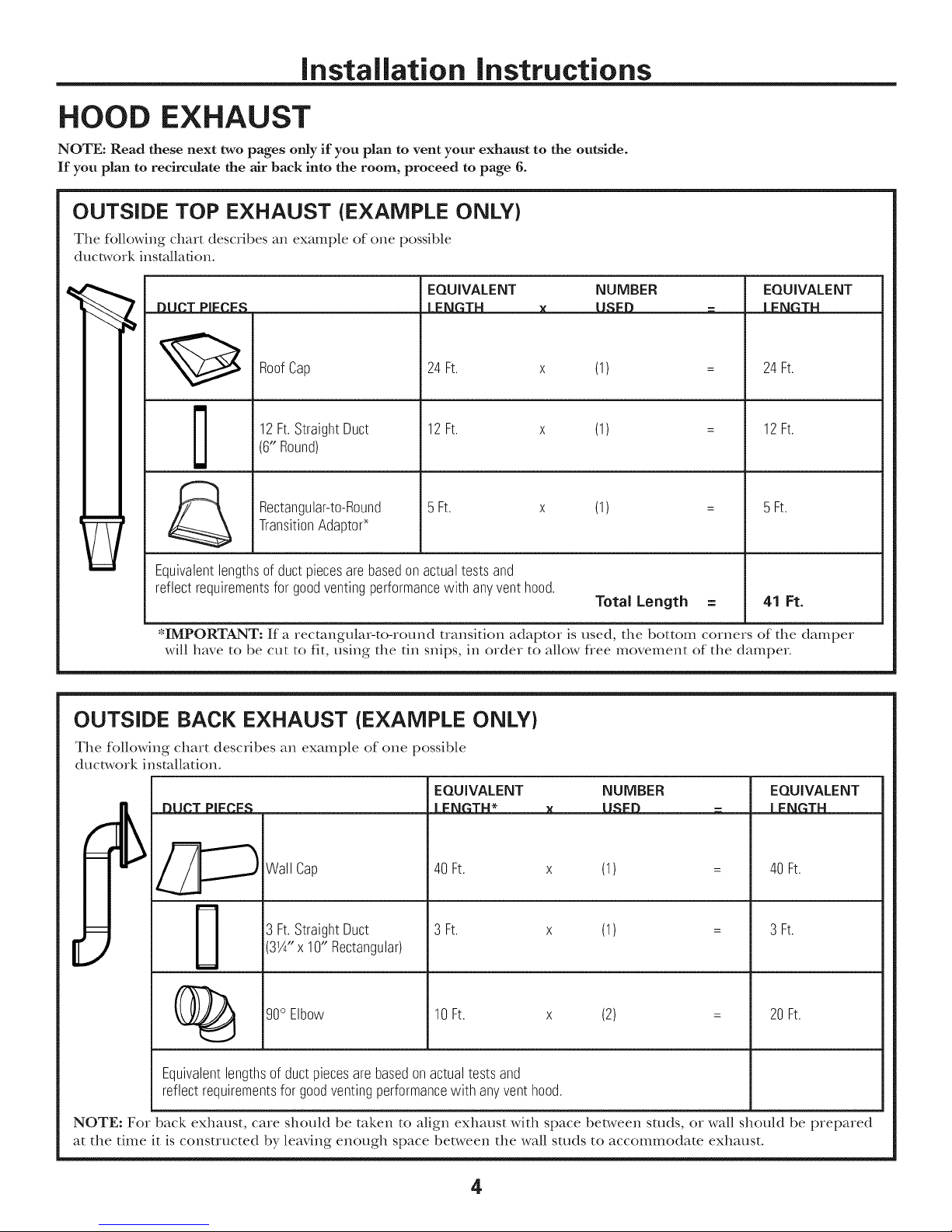
OUTSIDE TOP EXHAUST (EXAMPLE ONLY}
The fbllowing chart describes an example of one possible
ductwork installation.
EQUIVALENT NUMBER EQUIVALENT
IDDCI PIECES =LENGTH x USED = J LENGTH
24Ft. x (1) = 24Ft.
12Ft.StraightDuct
RoofCap
(6" Round)
TransitionAdaptor*
Rectangular-to-Round
Equivalentlengthsof ductpiecesarebasedon actualtests and
reflectrequirementsfor goodventingperformancewith anyventhood.
*IMPORTANT: If a rectangular-to-round transition adaptor is used, the bottom corners of the damper
will have to be cut to fit, using the tin snips, in order to allow flee movement of the damper.
12Ft. x (1) = 12Ft.
5 Ft. x (1) = 5 Ft.
OUTSIDE BACK EXHAUST (EXAMPLE ONLY)
The following chart describes an example of one possible
ductwork installation.
EQUIVALENT
13|lP.T PIFP.I:N
Wall Cap
I I::N_TM*
40 Ft.
Total Length = 41 Ft.
EQUIVALENT
I FN_TM
(1)
40 Ft.
3 Ft.StraightDuct
3W' x 10" Rectangular)
(_ go° Elbow 10 x (2) = 20
Equivalent lengths of duct pieces are based on actual tests and
reflect requirements for good venting performance with any vent hood.
NOTE: For back exhaust, care should be taken to align exhaust with space bet_,veen studs, or wall should be prepared
at the time it is constructed by leaving enough space between the wall studs to accommodate exhaust.
3 Ft.
Ft. Ft.
(1)
4
3 Ft.
Page 5
Installation instructions
NOTE: If you need to install ducts, note that the total
duct length of 3¼" x 10" rectangular or 6" diameter
round duct should not exceed 140 equivalent feet.
Outside ventilation requires a HOOD EXHAUST DUCT.
Read the fbllowing careflflly:
NOTE: It is important that venting be installed using
the most direct route and with as few elbows as possible.
This ensures clear venting of exhaust and helps prevent
blockages. Also, make sure dampers swing freely and
nothing is blocMng the ducts.
Exhaust connection:
The hood exhaust has been designed to mate with
a standard 3¼" x 10" rectangular duct.
If a round duct is required, a rectangular-to-round
transition adaptor must be used. Do not use less than
a 6" diameter duct.
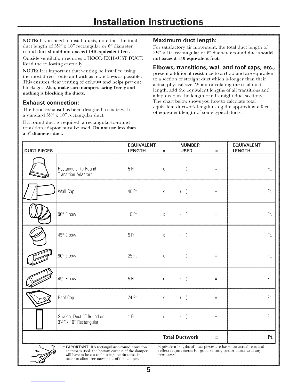
EQUIVALENT
DUCT PIECES
&
Rectangular-to-Round
TransitionAdaptoP
LENGTH
5Ft.
Maximum duct length:
For safisfhctory air movement, the total duct length of
3¼"x 10" rectangular or 6" diameter round duct should
not exceed 140 equivalent feet.
Elbows, transitions, wall and roof caps, etc.,
present additional resistance to airflow and are equivalent
to a section of straight duct which is longer than their
actual physical size. When calculating the total duct
length, add the equNa/ent lengths of all transitions and
adaptors plus the length of all straight duct sections.
The chart below shows you how to calculate total
equiwdent ducta, vork length using the approximate feet
of equivalent length of some typical ducts.
NUMBER
X
USED
( )
EQUIVALENT
LENGTH
Ft.
Wall Cap
90° Elbow
45° Elbow 5Ft. x ( ) = Ft.
90° Elbow 25 Ft. x ( ) = Ft.
45° Elbow 5Ft. x ( ) = Ft.
RoofCap 24 Ft. x ( ) = Ft.
Straight Duct 6" Roundor 1Ft. x ( ) = Ft.
3X" x 10" Rectangular
40 Ft.
10 Ft.
( )
( )
Ft.
Ft.
* IMPORTANT: If a rectangula>to-round transition
adaptor is used, the bottom corners of the damper
will ha_e to be cut to fit, using the tin snips, in
order to allow ti'ee movement of the damper.
Total Ductwork = Ft.
Equivalent lengths of duct pieces are based on actual tests and
reflect requirements for good velltillg performance x_dth any
Vellt hood.
5
Page 6
Installation instructions
DAMAGE - SHIPMENT/
iNSTALLATiON
• If the unit is damaged in shipment, return the
unit to the store in which it was bought for repair
or replacement.
• If the unit is damaged by the customer, repair or
replacement is the responsibility of the customer.
• If the unit is damaged by the installer (if other
than the customer), repair or replacement must
be made by arrangement bet_,veen customer and
installer.
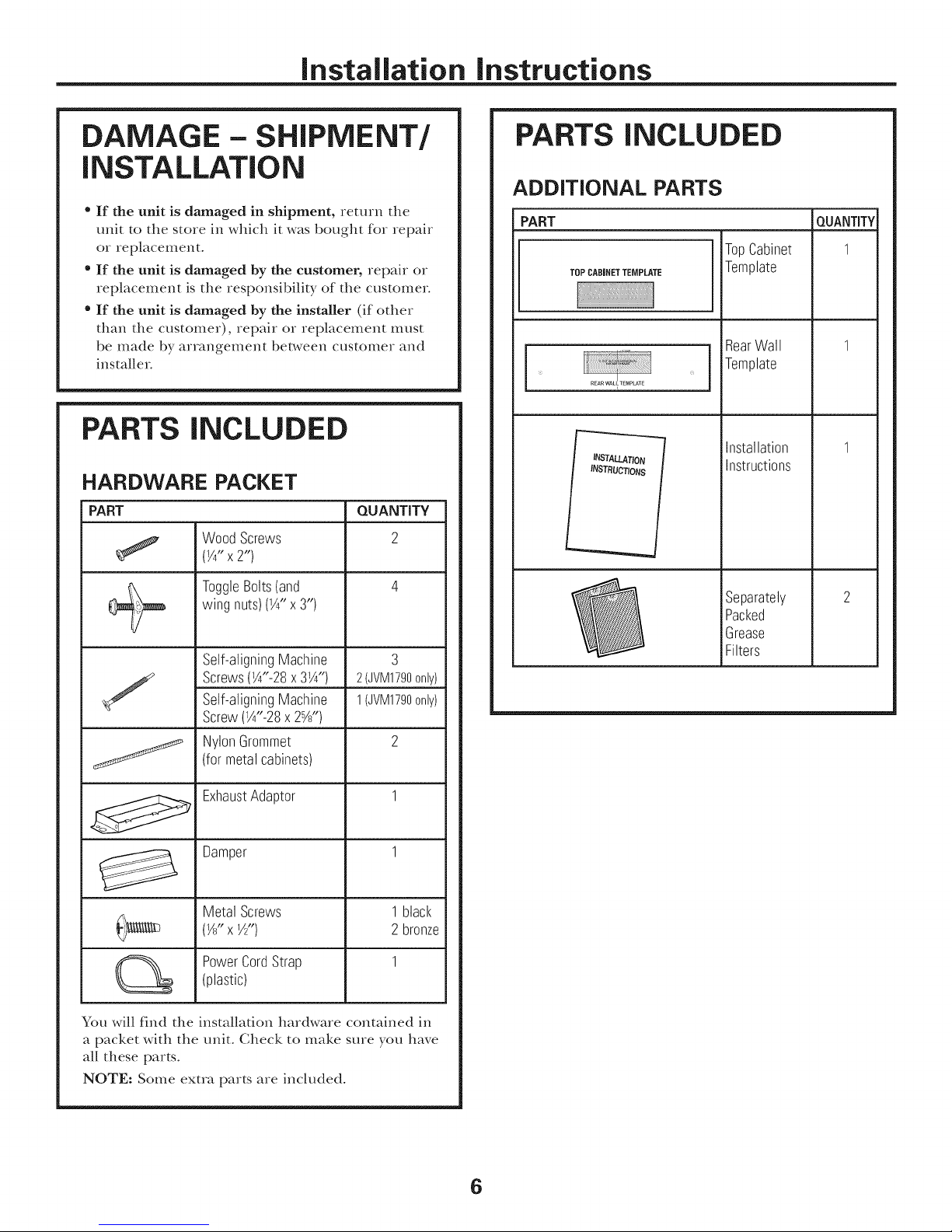
PARTS iNCLUDED
HARDWARE PACKET
PART QUANTITY
WoodScrews 2
(Yg'x2")
PARTS iNCLUDED
ADDITIONAL PARTS
PART
TopCabinet
TOPCABINET TEMPLATE
I
INSTALLATION
INSTRUCTIONS
Template
RearWall
Template
installation
instructions
m
QUANTITY
1
wingnuts)(1A"x
ToggleBolts(and3,,) 4
Self-aligningMachine
Screws(W'-28x 3W')
/
J
You will find the installation hardware contained in
a packet with the unit. Check to make sure you have
all these parts.
NOTE: Some extra parts are included.
Self-aligningMachine
Screw(W'-28x 2%")
NylonGrommet
(formetalcabinets)
ExhaustAdaptor 1
Damper 1
Metal Screws 1black
(1/8"xY2") 2 bronze
PowerCordStrap 1
(plastic)
3
2(JVM1790only)
1(JVM1790only)
2
Separately
Packed
Grease
Filters
6
Page 7

Installation instructions
TOOLS YOU WiLL NEED
# 1 and#2 Phillipsscrewdriver
Tinsnips(forcutting
damper,if required)
Gloves
Scissors
(tocuttemplate,if necessary)
Pencil
Ruleror tapemeasure
aightedge
Electricdrill with _6 , X_ ,
_" and%" drill bits
3 ,1 7 /z
8
Carpentersquare
(optional)
Fillerblocksor scrap
woodpieces,if needed
fortop cabinetspacing
(usedonrecessedbottom
cabinetinstallationsonly)
Saw(saber,holeor keyhole)
Safety goggles
MOUNTING SPACE
66" or more
fromthe floor
tothe top of
theoven
Bottomedgeof
cabinetneedsto
fromthe cooking
Bacl<splash
be30" or more
surface
Studfinder or
Level
NOTES:
• The space bet_,veen the cabinets must be , u wide
and f}ee of obstructions.
• If the space between the cabinets is g;eate;
than 30", a Filler Panel Kit may be used to fill
in the gap belween the oven and the cabinets.
Your Owner's Manual contains the kit numbe;
for your model.
• This oven is fbr installation over ranges up to
36" wide.
• If you are going to vent your oven to the outside,
see Hood Exhaust Section for exhaust duct
preparation.
• When installing the oven beneath smooth, fiat
cabinets, be careful to follow the instructions
on the top cabinet template for power cord
clearance.
• The depth of the opening cannot be more than
13-1/2".
Hammer(optional)
Duct and masking tape
\
7
Page 8

Installation instructions
[- PLACEMENT OF THE MOUNTING PLATE
A--71 EMOVING THE OVEN FROM
THE CARTON/REMOVING THE
MOUNTING PLATE
[] Open top of box and remove Styrofoam pack
containing installation instructions, filters, exhaust
adaptor, damper, and the small hardware bag.
[]Locate cut line at the bottom of the box and
carefully cut along the indicated dotted line.
Then pull the carton up and off the unit.
[]Remove the the front
of the oven. Open the oven door and remove
any contents f}om inside.
[_ Using a portion of the carton or other material
to protect the outer casing flom damage, stand
the oven on its side so the control panel is nearest
to the ground.
]The mounting plate is attached to the back
of the oven. Remove the two screws holding
the plate to the oven. The plate will serve
as the rear wall template and provide the support
to mount the oven to the wall.
]Once the plate has been removed, set the oven
upright. Remove and properly discard the plastic
bags and Styrofbam.
[_ Check that all adhesive has been
removed flom exhaust adapters, grease filters, and
the power supply cord.
St'_7I'O f}jaill protecting
to enstlie
tape
IB,---1FINDING THE WALL STUDS
l i i
Wall
Studs
i
Centeri_i
[_ Find the studs, using one of the fbllowing
methods:
A. Stud finder--a magnetic device which
locates nails.
OR
g. Use a hammer to mp lighdy across the
mounting surf_ce to find a solid sound.
This will indicate a stud location.
[_ After locating the stud(s), find the center by
probing the wall with a small nail to find the
edges of the stud. Then place a mark halfk,vW
between the edges. The center of any adjacent
studs should be 16" or 24 " f]om this mark.
[_ Draw line down the center of the studs.
THE OVEN MUST BE CONNECTED TO AT LEAST
ONE WALL STUD.
a
ControlPanelSide "" [ ................".
-- MountingPlate
8
Page 9
Installation instructions
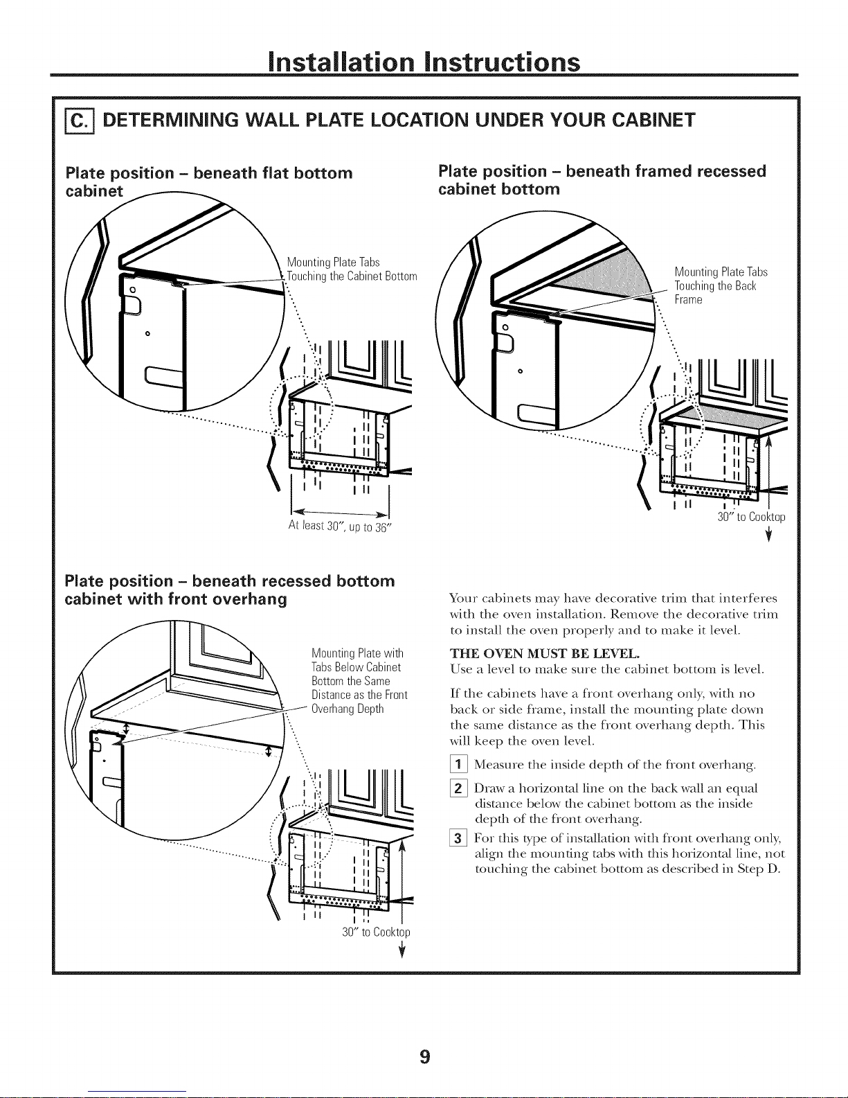
DETERMiNiNG WALL PLATE LOCATION UNDER YOUR CABINET
Plate position - beneath flat bottom
cabinet
MountingPlateTabs
ig the CabinetBottom
':o
o,
Plate position - beneath framed recessed
cabinet bottom
MountingPlateTabs
Touchingthe Back
Frame
II1
30"to Cool<top
Plate position - beneath recessed bottom
cabinet with front overhang
MountingPlatewith
TabsBelowCabinet
BottomtheSame
Distanceasthe Front
OverhangDepth
"-..
I II
30" to Cool<top
L
Your cabinets may have decorative trim that interferes
with the oven installation. Remove the decorative trhn
to install the oven properly and to make it level.
THE OVEN MUST BE LEVEL.
Use a level to make sure the cabinet bottom is level.
If the cabinets have a front overhang only, with no
back or side fiame, install the mounting plate down
the same distance as the front overhang depth. This
will
keep the oven level.
Measme the inside depth of the flont overhang.
%
Draw a horizontal line on the back wall an equal
distance below the cabinet bottom as the inside
depth of the fiont overhang.
%
For this t),pe of installation with fiont overhang only;
align the mounting robs with this horizontal line, not
touching the cabinet bottom as described in Step D.
9
Page 10

Installation instructions
ALiGNiNG THE WALL PLATE
HoleA
HoleD
0 0 0 0 0 0 0 0 0 0 0 0 0
0 010 0 0 0 0 0 0 0
CAUTION: Wear gloves
to avoid cutdng fingers on
sharp edges.
[]Draw a vertical line on the wall at the center of die
30" wide space.
[_] Use the mounting plato as the template for the rear
wall. Place the mounting plato on the wall, maMng
sure that the robs are touching the bottom of the
cabinet or the level line drawn in Step C for cabinets
with front overhang. Line up the notch and center line
on the mounting plate to the center line on the wall.
[] While holding the mounting plate with one hand,
draw circles on the wall at holes A, B, C and D (see
illustration above/actual plate marked with arrows).
Four holes must be used for mounting.
0 0 0 b
0 0
I
I
I
I
I DrawaVertical
i_ LineonWall
from Centerof
TopCabinet
I
I
I
I
0
j
I nn
I
NOTE: Holes C and D are inside area E. If neither
C nor D is in a stud, find a stud somewhere in area E
and draw a fifth circle to line up with the stud. It is
important to use at least one wood screw mounted
firmly in a stud to support the weight of the oven.
Set the mounting plate aside.
Drill holes on the circles. If there is a stud, drill a NJ'
hole for wood screws. For holes that don't line up with
a stud, drill a %" hole for toggle bolts.
NOTE: DO NOT MOUNT THE PLATE AT THIS TIME.
HoleD
10
Page 11

Installation instructions
INSTALLATION TYPES
This oven is designed for adaptation to the following
3 types of ventilation:
A. Outside Top Exhaust (Vertical Duct)
B. Outside Back Exhaust (Horizontal Duct)
Co Recirculating (Non-Vented Ductless)
OUTSIDE TOP EXHAUST
(VERTICAL DUCT)
Adapterin Placefor
OutsideTopExhaust
/
(Choose A, B or C}
NOTE: This oven is shipped assembled for Outside Top
Exhaust° Select the type of ventilation required for your
installation and proceed to that section.
OUTSIDE BACK EXHAUST
(HORIZONTAL DUCT)
RECIRCULATING
{NON-VENTED DUCTLESSi
A Charcoal Filter Accessory
Kit is required fin the
non-vented exhaust. (See your
Owner's Manual for the kit
number.)
11
Page 12

Installation instructions
OUTSIDE TOP EXHAUST (VerticalDuctl
iNSTALLATiON OVERVIEW
A1. Attach Mounting Plate to Wall
A2. Prepare Top Cabinet
A3o Install Adapter
A4. Mount Oven
AS. Adjust Exhaust Adaptor
A6. Connect Ductwork
ATTACH THE MOUNTING
PLATE TO THE WALL
Attach the plate to tile wall using toggle bolts.
At least one wood screw must be used to attach tile
plate to a wall stud.
_ Remove tile toggle wings flom tile bolts.
_ Insert tile bolts into the mounting plate through
tile holes designated to go into drywall and
reatmch the toggle wings to ¾" onto each bolt.
To use toggle bolts:
SpacingforToggles
MoreThanWall
+l_.!.,,_Th icl<ness
Mounting
Plate
_ Place the mounting plate against tile wall and
insert tile toggle wings into the holes in the wall
tO IIIOtlnt the plate.
NOTE: Before tightening toggle bolts and wood
screw, make sure the robs on the mounting plate
touch the bottom of the cabinet when pushed
flush against tile wall and that tile plate is properly
centered under tile cabinet.
CAUTION: Be careful to avoid pinching fingers
between tile back of tile mounting plate and the wall.
_ Tighten all bolts. Pull the plate away from tile wall
to help tighten tile bolts.
Wings
BoltEnd
12
Page 13
Installation instructions
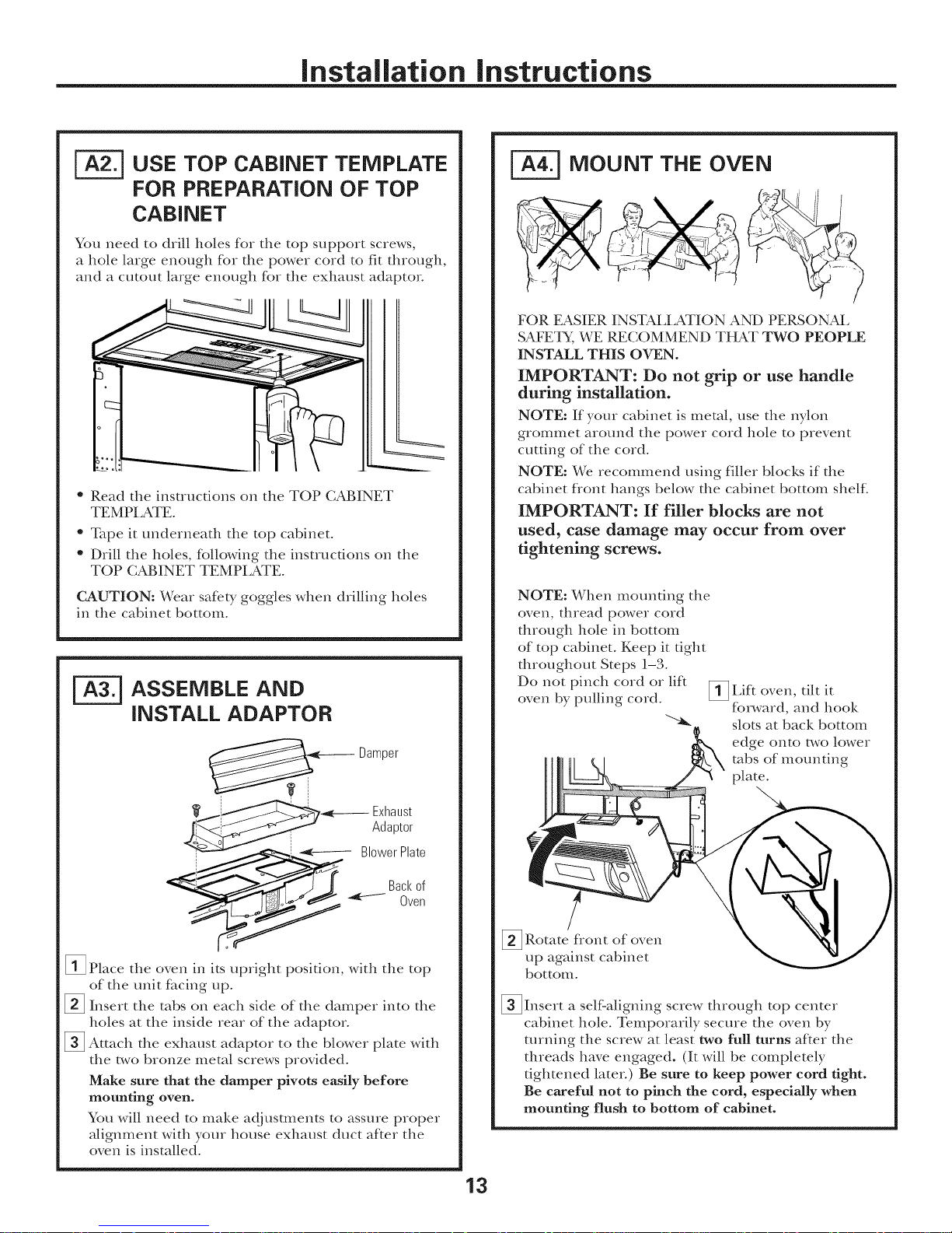
[-_ USE TOP CABINET TEMPLATE
FOR PREPARATION OF TOP
CABINET
You need to drill holes for the top support screws,
a hole large enough for the power cord to fit through,
and a CUtOUt large enough for tile exhaust adaptor.
• Read the instructions on tile TOP CABINET
TEMPI ATE.
• Tape it underneath the top cabinet.
• Drill the holes, tbllowing the instructions on the
TOP CABINET TEMPLATE.
CAUTION: Wear safety goggles when drilling boles
in the cabinet bottom.
ASSEMBLE AND
iNSTALL ADAPTOR
Damper
MOUNT THE OVEN
FOR EASIER INSTALLATION AND PERSONAL
SAFETY, WE RECOMMEND THAT TWO PEOPLE
INSTALL THIS OVEN.
IMPORTANT: Do not grip or use handle
during installation.
NOTE: If your cabinet is metal, use the nylon
grommet around tlle power cord hole to prevent
cutting of the cord.
NOTE: We recommend using filler blocks if the
cabinet f?ont bangs below tile cabinet bottom shelf.
IMPORTANT: If filler blocks are not
used, case damage may occur from over
tightening screws.
NOTE: When mounting tile
oven, thread power cord
through hole in bottom
of top cabinet. Keep it fight
throughout Steps 1-3.
Do not pinch cord or lift
oven by pulling cord.
_Lift tilt itoven,
forward, and hook
slots at back bottom
edge onto two lower
robs of mounting
plate.
_,_2_ BlowerPlate
[]Place tile oven in its upright position, with the top
of the unit fi_cing up.
[]Insert tile tabs on each side of the damper into tile
boles at tile inside rear of tile adaptor.
_ Attach the exhaust adaptor to the blower plate with
tile two bronze metal screws provided.
Make sure that the damper pivots easily before
mounting oven.
You will need to make adj usunents to assure proper
alignment with your house exhaust duct af_er the
oven is installed.
-- Exhaust
Adaptor
-I
[] Rotate flont of
up against cabinet
bottom.
_Insert a self:aligning screw through top center
cabinet hole. Temporarily secure tlle oven by
turning the screw at least two full turns after the
threads have engaged. (It will be completely
tightened later.) Be sure to keep power cord tight.
Be careful not to pinch the cord, especially when
mounting flush to bottom of cabinet.
oven
13
Page 14

Installation instructions
_] MOUNT THE OVEN {continuedl
Cabinet Front
Cabinet Bottom Shelf
Filler Block
Depth
ofCabinet
i quivalentto
Recess
Self-AligningScrew
Oven Top
[]Attach the oven to the top cabinet°
Insert 2 self aligning screws
(¼"-28 x . ¼ ) through outer
top cabinet holes. Turn t_,vo
full turns on each screw.
,_l pt
t
I
/
L===========_
ADJUST THE EXHAUST
ADAPTOR
Open the top cabinet and adjust the exhaust adaptor
to connect to the house duct.
Damper
CONNECTING DUCTWORK
HouseDuct
[]Tighten center
screw completely.
NOTE: Use self:aligning screw, ¼"-28 x 2_ , on
t ,_ l/'",_qVl1790 and self aligning screws, ¼"-28 x, y4 ,
on J\qV/1490, SCA1000, and SCA1001.
[] Tighten the outer la,vo screws to the top of the
oven. (While tightening screws, hold the oven in
place against the wall and the top cabinet.)
c5 rz
/o/
[] Install grease filters. See the Owner's Manual
packed with the oven.
[]Extend the house duct down to connect to
the exhaust adaptor
[] Seal exhaust duct joints using duct rope.
14
Page 15

installation instructions
OUTSIDE BACK EXHAUST IHorkontalDuctl
iNSTALLATION OVERVIEW
B1. Prepare Rear Wall
B2. Attach Mounting Plate to Wall
B3. Prepare Top Cabinet
B4. Adjust Blower
BS. Mount the Oven
_=_ PREPARING THE REAR WALL
llaaaaaaaaaai=
FOR OUTSIDE BACK EXHAUST
You need to cut an opening in the rear wall for
outside exhaust.
* Read the instructions on the REAR WALL
TEMPI ATE.
. Tape it to the rear wall, lining up with the holes
previously drilled fbr holes A and B in the wall
plate.
. Cut the opening, following the instructions of the
REAR WALL TEMPLATE.
_-] ATTACH THE MOUNTING
I_==========,_
PLATE TO THE WALL
i
, i
Attach the plate to the wall using toggle bolts. At least
one wood screw must be used to attach the plate to
a wall stud.
_ Remove the toggle wings flom the bolts.
_ Insert the bolts into the mounting plate through
the holes designated to go into drywall and reatmch
the toggle wings to ¾" onto each bolt.
15
Page 16

Installation instructions
To use toggle bolts:
SpacingforTogglesMore
-*@-@,_ ThanWall Thickness
IVl " IToggleWings
ountmg •
" '."i Toggle .,:
Platedllii':l, }/Bolt ]l I;':.ilk
III : I_-Wall II I:1 [
[]Place the mounting plate against the wall and
insert the toggle wings into the boles in the wall
to mount the plate.
NOTE: Before tightening toggle bolts and wood
screw, make sure the tabs on the mounting plate
touch the bottom of the cabinet when pushed flush
against the wall and that the plate is properly
centered under the cabinet.
CAUTION: Be careflfl to avoid pinching fingers
between the back of the moundng plate and the wall.
[]Tighten all bolts. Pull the plate away from the wall
to help dghten the bolts.
BoltEnd
_-_ ADAPTING BLOWER FOR
OUTSIDE BACK EXHAUST
_ Remove the three that hold the blower
plate to the oven. Slide blower plate flom under
its retaining flange. Remove and save the screw
that holds blower motor to oven.
Retaining _:_:_..._
FIange-..` ._...._.__-,____ BlowerPlate
__ e___BlowerMotor
_-yy Screw
_ Careflflly the blower unit. The wirespull
will extend far enough to allow you to adjust
the blower unit.
EndA
screws
()lit
EndB
_-_ USE TOP CABINET TEMPLATE
FOR PREPARATION OF TOP
CABINET
You need to drill boles for the top support screws and
a hole large enough for the power cord to fit through.
• Read the instructions on the TOP CABINET
TEMPI ATE.
• Tape it underneath the top cabinet.
• Drill the holes, following the instructions on the
TOP CABINET TEMPLATE.
CAUTION: Wear safe b, goggles when drilling boles
in the cabinet bottom.
[Rotate blower unit counterclockwise 180 °.
BeforeRotation
Oven
_ Gently the wires flom the
Reroute the wires through grooves on other side
of the blower unit.
WiresRoutedThroughRightSide Wires RoutedThroughLeftSide
reInove
BeforeRerouting After Rerouting
After Rotation
Oven
grooves.
16
Page 17

Installation instructions
]Roll the blower unit 90 ° so that fan blade
openings are facing out the back of the oven.
BeforeRolling
Backof
Oven
Locate the t_,vo"knockout" plates, on the rear
%
oven panel, near the top of the oven.
Using un snips, carefhlly cut tile web area f}om
the two boles side-by-side (that secure tile
knockouts to tile oven). Cut all fore webs on both
rear knockouts; this will allow the vendlauon fan
airflow to exhaust out the rear of tile oven.
CAUTION: Be sure to trim the sharp edges from
the openings after removing the knockout plates.
Oven Rear Panel
Snipall 4webs
oneachknockout
panelandremove
themetalknockouts
[] Replace the blower plate in the same position
as befbre with the screws.
BlowerPlateScrews
g g_/ Blower Plate
•i<-- / BackofOven
_ Insert tile tabs each side of tile intodamper
the boles at the inside rear of the adapton
_ Attach tile exhaust adaptor to the _ear of the
oven by sliding it into the guides at tile top
center of tile back of tile oven.
ExhaustAdaptor
on
l
-_-----__Exhaust
Adaptor
Damper
sideup)
forrearairflow.
[]Place tile blower unit back into the opening.
EndA
CAUTION: Do not pull or stretch the blower
unit wiring. Make sure the wires are not pinched.
NOTE: The blower unit exhaust openings should
match exhaust openings on rear of oven.
Slideexhaust
adaptorinto
guideson
ovenrear.
o
Push in securely until it is in the lower locking
tabs. Take care to assure tile damper binge is
installed so that it is at tile top and that tile
damper swings f_eel>
BackofOven
Guides
_ Secu,e the exhaust adaptoI to tile oven with the
two bronze metal screws provided.
17
Page 18

Installation instructions
_=_ MOUNT THE OVEN
Cabinet Front
Cabinet Bottom Shelf
Filler Block
i quivalent
to Depth
ofCabinet
Recess
FOR EASIER INSTALLATION AND PERSONAL
SAFETY, WE RECOMMEND THAT TWO PEOPLE
INSTALL THIS OVEN.
IMPORTANT: Do not grip or use handle
during installation.
NOTE: If your cabinet is metal, use the nylon
grommet around the power cord hole to prevent
cutting of the cord.
NOTE: We recommend using filler blocks if the
cabinet fiont bangs below the cabinet bottom shelfi
IMPORTANT: If filler blocks are not
used, case damage may occur from over
tightening screws.
NOTE: When mounting
the oven, thread power
cord through hole in
bottom of top cabinet.
Keep it tight throughout
Steps 1-3. Do not pinch
cord or lift oven by
pulling cord.
[]Lift oven, tilt it
forward, and hook
slots at back bottom
edge onto two lower
robs of mounting plate.
Self-AligningScrew
0venTop
_ Attach the oven to the top cabinet.
Insert 2 self'aligning screws
(¼"-28 x , ¼ ) through outer
,_1 pt
top cabinet boles. Turn two
full ttlrns on each screw.
g
I
_ Tighten center
screw completely.
NOTE: Use self'aligning screw, ¼"-28 x 2_ , on
JVM1790 and self'aligning screws, ¼"-28 x, y4 ,
on ,_/M 1490, SCA1000, and SCA1001.
c 5 ii
,_IX pt
[]Rotate flont of oven up
against cabinet bottom.
[]Insert a self'aligning screw through top center
cabinet hole. Temporarily secure the oven by
turning the screw at least two full turns after the
threads have engaged. (It will be completely
tightened later) Be sure to keep power cord tight.
Be careful not to pinch the cord, especially when
mounting flush to bottom of cabinet.
[] Tighten the outer ta,vo screws to the top of the
oven. (While tightening screws, hold the oven
in place against the wall and the top cabinet.)
_ Install grease filters. See the Owner's Manual
packed with the oven.
18
Page 19

Installation instructions
RECIRCULATING
iNSTALLATiON OVERVIEW
C1. Attach Mounting Plate to Wall
C2. Prepare Top Cabinet
C3. A(0 ust Blower
C4. Mount the Oven
C5. Install Charcoal Filter (not supplied)
ATTACH THE MOUNTING
PLATE TO THE WALL
(Non-Vented Ductless)
_ Place the mounting plate against the wall and
insert the toggle wings into tile boles in tile wall
to I'tlOllllt the plate.
NOTE: Before tightening toggle bolts and wood
screw, make sure the robs on the mounting plate
touch the bottom of the cabinet when pushed flush
against tile wall and that tile plate is properly
centered under the cabinet.
CAUTION: Be careflfl to avoid pinching fingers
between the back of tile mounting plate and tile wall.
_ Tighten all bolts. Pull the plate away from tile wall
to help tighten tile bolts.
Attach tile plate to the wall using toggle bolts. At
least one wood screw must be used to attach tile
plate to a wall stud.
[]Remove tile toggle wings f_om the bolts.
[]Insert the bolts into tile mounting plate through
the holes designated to go into drywall and
reatmch the toggle wings to ¾" onto each bolt.
To use toggle bolts:
SpacingforToggles
MoreThanWall
-_l_i_--Thicl<ness
Mounting
Plate
Wings
BoltEnd
USE TOP CABINET TEMPLATE
FOR PREPARATION OF TOP
CABINET
You need to drill boles for the top support screws and
a hole large enough for the power cord to fit through.
* Read the instructions on the TOP CABINET
TEMPI ATE.
* Tape it underneath the top cabinet.
o Drill the boles, fbllowing the instructions on the
TOP CABINET TEMPLATE.
CAUTION: Wear safeb_ goggles when drilling boles
in the cabinet bottom.
19
Page 20

Installation instructions
ADAPTING BLOWER
FOR RECIRCULATION
NOTE: The exhaust adaptor with damper is not
needed for recirculating models. You may want to
save them for possible future use.
[]Remove and save screws that hold blower plate to
the oven°
_'; _ _ SlowerPlateScrews
[]Slide the blower from under itsplate retaining
flange and lift it off. Remove and save screw that
holds the blower motor to oven°
Retaining __
[] Careflflly pull out the blower unit. The wires
will extend far enough to allow you to adjust the
blower unit.
[]Roll the blower trait 90 ° so that fan blade openings
are fi_cing toward the flont of the oven.
"-'_e _ BlowerMotor
[ ;_ Screw
R011
ower te
NOTE: Make sure wires remain routed in the
grooves of the motor flame.
20
Page 21

Installation instructions
ADAPTING BLOWER FOR
RECIRCULATION (continued)
_ Place the blower unit back into the opening.
CAUTION: Do not pull or stretch the blower unit
wiring. Make sure the wires are not pinched.
J
[]Secure blower unit to oven with the screw
removed in Step 2. Insert the screw in bottom
right screw hole on the back of the oven.
[]Replace blower plate with the screws removed in
Step 1.
_---- SlowerPlateScrews
BackofOven
-----------4
_o,55:___ _qq[:_-Blower Motor
I _,r Screw
MOUNT THE OVEN
NOTE: When mounting
the oven, thread power
cord through hole in
bottom of top cabinet.
Keep it tight throughout
Steps 1-3. Do not pinch
cord or lit* oven by
pulling cord.
_Liff oven, tilt it
forward, and hook
slots at back bottom
edge onto two lower
tabs of mounting plate.
/
_Romte front of oven
up against cabinet
bottom.
_Insert a self'aligning screw through top center
cabinet hole. Temporarily secure the oven by
turning the screw at least two full turns after the
threads have engaged. (It will be completely
tightened later.) Be sure to keep power cord tight.
Be careful not to pinch the cord, especially when
mounting flush to bottom of cabinet.
CabinetFront
CabinetBottomShelf
FillerBlock
FOR EASIER INSTALLATION AND PERSONAL
SAFETY, WE RECOMMEND THAT TWO PEOPLE
INSTALL THIS OVEN.
IMPORTANT: Do not grip or use handle
during installation.
NOTE: If your cabinet is metal, use the nylon
grommet around the power cord hole to prevent
cutting of the cord.
NOTE: We recommend using filler blocks if the
cabinet flont hangs below the cabinet bottom shelf.
IMPORTANT: If filler blocks are not used,
case damage may occur from over tightening
screws.
Equivalentto Depth
of CabinetRecess
Self-AligningScrew
Oven Top
_Attach the oven to the top cabinet.
21
Page 22

Installation instructions
MOUNT THE OVEN
{continuedl
Insert 2 self'aligning screws
(¼"-28 x, ¼ ) through outer
top cabinet boles. Turn two
full turns on each screw.
NOTE: Use self:aligning screw, ¼"-28 x 2%", on
JVM1790 and self:aligning screws, ¼"-28 x , '/4 ,
on ._/M 1490, SCA1000, and SCA1001.
[] Tighten the outer two screws to the top of the
oven. (While tightening screws, hokt the oven
in place against the wall and the top cabinet.)
,_1 ,t
screw completely.
_K 't
iNSTALLiNG THE
CHARCOAL FILTER
[] Remove 2 screws on top of oven, j ust above the
grille panel, using a Phillips screwdriver. Remove
one screw on the leR side.
[]Open the door.
[] Remove the grille.
screws
Scre_ -
[]Insert the filter into the sho\,vn,
maneuvering it behind the plastic grille tmtil it fits
squarely into place. It will rest at an angle behind
the plastic grille on two side support robs and in
fiont of the right rear rob. When properly
installed, the wire mesh of the filter should be
visible fiom the fiont.
oven as
[ Install grease filters. See the Owner's Manual
packed with the oven.
,/
[]Replace the grille and the 2 top screws.
Close the door and replace left side screw.
Insertmesh-sidedown
22
Page 23

Installation instructions
BEFORE YOU USE YOUR OVEN
Make sure the oven has been installed
according to instructions.
_ Remove all packing material flom the oven.
= m
_7] Read the Owner's Manual.
[=_ KEEP INSTALLATION INSTRUCTIONS
FOR THE LOCAL INSPECTOR'S USE.
_V] Replace house fuse or mrn breaker back on.
Plug power cord into a dedicated 15 to 20 amp
electrical outlet.
F
t
F
.I
23
Page 24

49-405901 (07-08 JR)
P_inted in Ko_ea
24
Page 25

me
|
sta
ANTES DE ENIPEZAR
orno para
[]
encim8 e
colocar
aest a
JVM1490,JVM1790,SCA1000ySCA1001
Lea estas instrucciones completa y cuidadosamente.
• IMPORTANTE - Gu_-_t__
instrucciones para el uso del inspector local.
• IMPORTANTE - c_,mp_,.,.
todos los c6digos y ordenanzas gubernamentales.
• Nota para el instalador - Asegfiresede dejar
esms instrucciones con el consumidor.
* Nora para el consumidor - Guarde esms
instrucciones pare flm_ra referencia.
* Nivel de destrezas - La insmlacidn de este aparato
requiere de destrezas bdsicas de mec_inica y electricidad.
* La instalacidn apropiada es responsabilidad
del insmlador.
* La falla del producto debido a una insmlacidn
inapropiada no est:i cubierm pot la garantia.
LEA CUIDADOSAMENTE.
GUARDE ESTAS INSTRUCCIONES.
25
Page 26
Instrucciones de instalaci6n
CONTENIDO
Informaci6n general
Instrucciones de seguridad importantes ................ 27
RequMtos el_ctricos .............................................. 27
Campana de escape .......................................... 28, 29
Dafios - Envio / Instalad6n .................................. 30
Partes incluidas ...................................................... 30
Herramientas que necesitarfi .................................. 31
Espado de montaje ................................................ 31
Guia de instalaci6n paso pot paso
C6mo colocar el plato de montaje .................... 32-34
C6mo remover el plato de mon@e ............ 32
Cdmo encontrar madera s61ida
en la pared .................................................. 32
C6mo determinar la localizaci6n
de las placas de la pared ............................ 33
[] Recirculacidn ........................................ 43-46
Cdmo adherir el plato de
mont_tje a la pared .............................. 43
Cdmo preparer el gabinete superior....43
Cdmo adaptar el calefactor
para la recirculacidn ...................... 44, 45
Cdmo monmr el homo .................. 45, 46
Cdmo insmlar el filtro de carbonilla....46
Antes de comenzar a usar su horno ...................... 47
C6mo alinear la placa de la pared .............. 34
Tipos de instalaci6n .......................................... 35-46
_ Escape superior .......................
C6mo adherir la placa de
mont:_je a la pared .............................. 36
Preparaci6n del gabinete superior ...... 37
Cdmo inspeccionar si la operacidn
del regulador de fifo es apropiada ...... 37
Cdmo montar el homo .................. 37, 38
Cdmo _jusmr el adapmdor de escape ..38
Cdmo conecmr la red de conductos .... 38
_] Escape posterior externo ......................
Cdmo preparar la pared posterior
pare el escape posterior exterior ........ 39
Cdmo adherir el plato de
mont:tje a la pared ........................ 39, 40
Cdmo preparar el gabinete superior....40
exterior. 36-38
39-42
Cdmo adaptar el calefactor para
el escape exterior posterior. ........... 40, 41
Cdmo montar el homo ........................ 42
26
Page 27
Instrucciones de instalacion
INSTRUCCIONES DE SEGURIDAD IIVIPORTANTES
Este producto requiere un tomacorriente el_ctrico
de tres paras conecmdo a fierra. E1 instalador debe
llevar a cabo tma inspeccidn de confinuidad a fierra
en la c_ia el_ctrica antes de comenzar la instalacidn
para asegurar que la c_ja tomacorriente estg conecmda
a tierra de manera apropiada. Si no lo est_i, o si el
tomacorriente no cumple con los requisitos
el_ctricos indicados (b_io la seccidn REQUISITOS
ELt_CTRICOS), se deber_i recurrir a un t_cnico
calificado pare corregir cualquier deficiencia.
i remueva el fusible de
w
PRECAUCI()N: En pos de la seguridad personal,
la superfide de montaje debe ser capaz de soportar
la carga del gabinete, ademfis del peso adicional
(de 63 a 85 fibras) de este producto, mAs las cargas
adicionales del horno de hasta 50 fibras o un peso total
entre ll3 y 135 fibras.
PRECAUCION: En pos de la seguridad personal,
este producto no puede ser instalado en sistemas de
gabinetes tales como los llamados "islas" o "peninsulas".
Este debe ser montado tanto a un gabinete superior
como a una pared.
NOTA: Para una instalacidn mAs filch yen pos de la
seguridad personal, se recomienda que dos personas
instalen este producto.
IMPORTANTE: POR FAVOR, LEA
CUIDADOSAMENTE. EN POS DE LA SEGURIDAD
PERSONAL, ESTE APARATO DEBE SER
CONECTADO A TIERRA APROPIADAMENTE PARA
EVITAR DESCARGAS SEVERAS O FATALES.
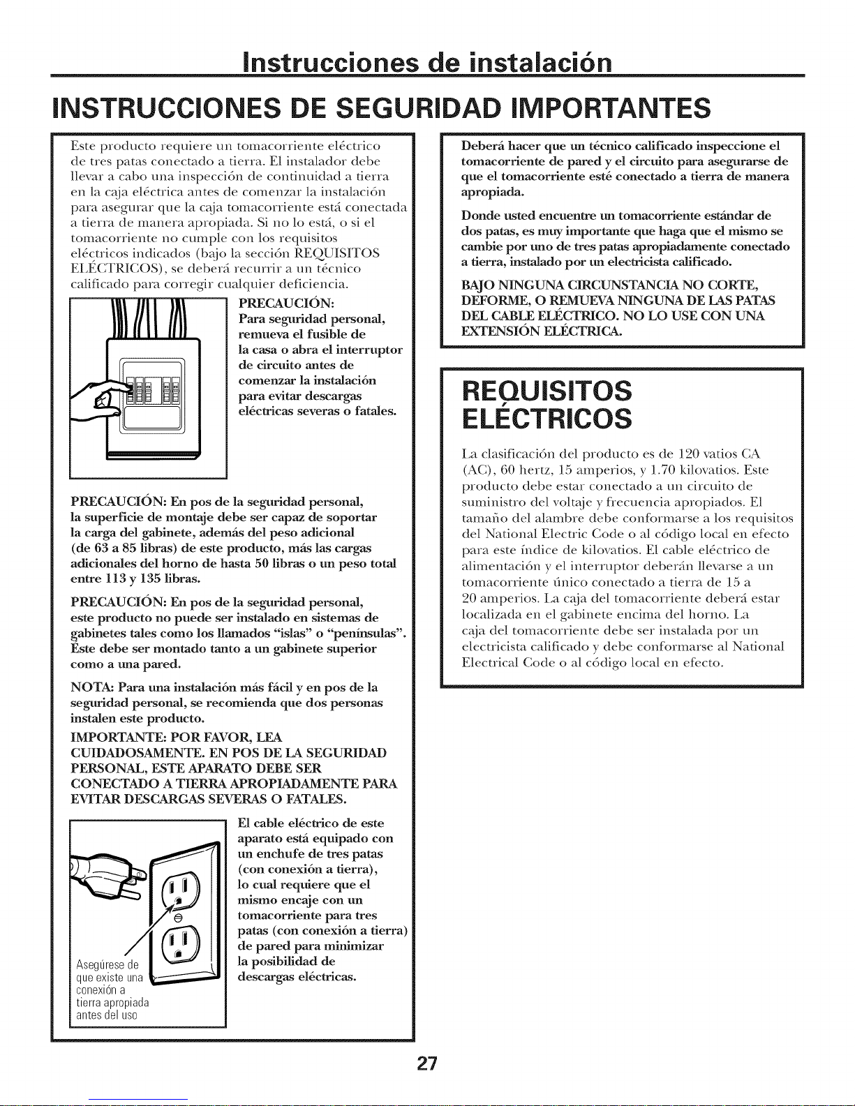
Asegdrese de
que existe una
conexidn a
tierra apropiada
antes del uso
Para seguridad personal,
la casa o abra el interruptor
de circuito antes de
eomenzar la instalaeidn
para evitar descargas
el_ctricas severas o fatales.
E1 cable el6ctrico de este
aparato estfi equlpado con
un enchufe de tres paras
(con conexidn a tierra),
lo cual requiere que el
mismo encaje con un
tomacorriente para tres
paras (con conexi6n a tierra)
de pared para minimizar
la posibilidad de
descargas el_ctricas.
Deberi hacer que un t_cnico calificado inspeccione el
tomacorriente de pared y el circulto para asegurarse de
que el tomaeorriente est_ conectado a tierra de manera
apropiada.
Donde nsted encuentre un tomacorriente esffmdar de
dos paras, es muy importante que haga que el mismo se
carnble por uno de tres paras apropiadamente coneetado
a fierra, instalado por un electridsta calificado.
BAJO NINGUNA CIRCUNSTANCIA NO CORTE,
DEFORME, O REMUEVA NINGUNA DE LAS PATAS
DEL CABLE ELt_CTRICO. NO LO USE CON UNA
EXTENSION ELI_CTRICAo
REQUISITOS
f
ELECTRICOS
La clasificacidn del prodt_cto es de 120 ratios CA
(AC), 60 hertz, 15 amperios, y 1.70 kilovafios. Este
prodt_cto debe esmr conectado a un circt_ito de
suministro del voltx_ie y fiecuencia apropiados. E1
mmafio del alambre debe conf_rmarse a los requisitos
del National Electric Code o al cddigo local en efecto
para este fndice de kilovafios° E1 cable eldctrico de
alimenmcidn y el interruptor deberfin llevarse a un
tomacorriente dnico conecmdo a tierra de 15 a
20 amperios. La c_ja del tomacorriente deberfi esmr
localizada en el gabinete encima del homo. La
c_ja del tomacorriente debe set instalada pot un
electricism calificado y debe confk_rmarse al National
Electrical Code o al cddigo local en efecto.
27
Page 28

Instrucciones de instalaci6n
CAMPANA DE ESCAPE
NOTA: Lea las Mguientes dos pfiginas solamente si planea ventilar el escape hacia el exterior.
Si pot el contrario planea recircular el aire de vuelta hada el sal6n, continfie en la pfigina 30.
ESCAPE SUPERIOR EXTERNO (EJEIViPLO SOLAIVIENTE)
La siguiente tabla describe un ejemplo de una posible
insta/aci6n de red de conductos.
LONGITUD NOMERO LONGITUD
PARTES DEL ONDUCTO
EOUIVALENTE × USADO = EOUIVALENTE
24pies x (1)
Conducto recto de 12 pies
(redondo de 6")
• . _
Adaptador de transici6n 5 pies x (1) = 5 pies
de rect_finguloa redondo_
12pies x (1)
LaIongitudde las partesde losconductosequivalentesest8basadaen pruebasrealesy reflejanlos
requisitosparaIograrunabuenaventilaciOnconcualquiercampanade escape.
Longitud total =
*IMPORTANTE: Si se usa un adapmdor de transicidn de rect_ingtflo a redondo, las es(
del regulador de tiros deber_n cormrse para que enc_jen, usando las tijeras de corte
movimiento libre del regulador de tiros.
ESCAPE POSTERIOR EXTERNO (EJEIVIPLO SOLAIVIENTE)
La siguiente tabla describe un ejemplo de una posible
insmlacidn de red de conductos.
LONGITUD N01VIERO
PARTES DEL CONDUCTO
EOUIVALi_NTE x USADO
24pies
12pies
41 pies
uinas del f_mdo
para permitir el
LONGiTUD
EOUIVALENTE
Tapadepared 40pies x (1)
Conductorectode3 pies
(rectangularde31A" x 10")
Codode90°
LaIongituddelas partesde losconductosequivalentesest8basadaenpruebasrealesy reflejan los
requisitosparaIograrunabuenaventilaciOnconcualquiercampanadeescape..
NOTA: Para el escape posterior, se debe tenet cuidado al alinear el escape entre los espacios de los postes de xiga de la pared,
o la pared deberfa set preparada en el momento de su construccidn dejando suficiente espacio entre los postes de xiga de la
pared para acomodar el escape.
3 pies x (1)
10pies x (2)
28
40pies
3 pies
20pies
Page 29

Instrucciones de instalaci6n
NOTA: Si usted necesita instldar conductos, tenga
pendiente que la longimd total del conducto rectangular
de 3¼" x 10" o el conducto redondo de 6" de di_metro
no debe sobrepasar 140 pies equivalentes.
La venfilacidn externa requiere un CONDUCTO DE
CAMPANA DE ESCAPE. Lea lo siguienm cuidadosamente.
NOTA: Es impormnm que la venfilacidn sea insta/ada
usando la mm mAs direcm y con la menor canfidad de codos
posible° Esto asegma la venfilacidn del escape y ayuda a
prevenir bloqueoso Tambi6n, cerddrese de que el regulador
de tiro pende libremente y nada bloquea los conductos.
Conexiones de escape:
i_ campana de escape ha sido diseflada para enc_iar con
un conducto rectangular de 3¼" x 10" est_inda_:
N un conducto redondo es necesafio, se debe usar un
adapmdor de transicidn de rectangular a redondoo
No use un conducto menor de 6" de difimetro.
LONGITUD NOMERO
PARTES DE CONDUCTO
&
Adaptadordetransici0n de
reckinguloa redondo_
EQUIVALENTE x USADO
5pies
Longitud maxima del conducto:
Para lograr un movimiento satisfi_ctorio del aire, la
longimd total del conducto rectangular de 3¼" x 10"
o el conducto redondo de 6" de di;imetro no debe
sobrepasar 140 pies equivalentes.
Los codos, transiciones, paredes y tapas
de techo, etc., presenmn resistencia adicional al
flt{io de aire y son equivalentes a una seccidn de
conducto recto el cual es m_is largo que su tamafio fl'sico
real Cuando calcule la longimd total del conducto,
agregue las longitudes equivalentes de todas las
transiciones y adaptadores, m_is la longimd de todas
las secciones de conducto recmso La tabla re;is adelante
muestra cdmo puede calcular la longimd aproximada
de Ia red de conductos usando pies aproximados de
longitudes equivalentes de algm_os conductos tfpicoso
LONGITUD
EQUIVALENTE
( )
pies
Tapadepared
(_ Codode90 °
Codo de 45° 5 pies x ( ) = pies
Codo de 90° 25 pies x ( ) = pies
Codo de 45° 5 pies x ( ) = pies
Tapa de techo 24 pies x ( ) = pies
Conducto recto de 6" redondo 1 pies x ( ) = pies
o rectangular de 3W' x 10"
40 pies
10pies
( )
( )
pies
pies
* IMPORTANTE: Si se usa tm adaptador de transici6n de
rect_ingulo a redondo, las esquinas del iondo del regulador
de tiros deber_in set cortadas para clue encaien, usando las
tijeras de corte, para permitir el movimient_ libre del
regulador de tiros.
29
Total red de conductos = pies
La longimd de las partes de conductos equivalentes est_ basada
en pruebas reales y refleian los requisitos para lograr tma bueml
ventilacidn con cualquier campana de escape.
Page 30

Instrucciones de instalaci6n
DAI OS - ENViO /
INSTALACION
• Si la unidad se dafia durante el envio, devuelva la
unidad al almac&l donde la adquiri6 para su
reparaci6n o reemplazo.
• Si el diente dafia la unidad, la reparaci6n o el
reemplazo es responsabilidad del cliente.
• Si el instalador dafia la unidad (si no es el cliente),
la reparaci6n o reemplazo se debe hacer pot
medio de un arreglo entre el cliente y el insmlador.
PARTES iNCLUIDAS
PAQUETE DE ELEMENTOS
PARTE CANTIDAD
(Y4"xT°rnill°2!')demadera 2
(ytuercasdemariposa)
Tornillosbasculantes 4
(Y4"x3")
Tornillosdem_iquina
autoalineables
(Yg'-28x 3Yg')
3
2(JVM1790SOlo
PARTES IRCLUIDAS
PARTES ADICIONALES
PART
Plantillapara
TOPCABINET TEMPLATE
INSrALLA;qON
INSTRUCTf0N$
el gabinete
superior
Plantillapara
lapared
)osterior
Instrucciones
de instalaciOn
Filtrosde
grasa
empacados
porseparado
m
CANTIDAD
1
m
2
Tornillosdem_iquina
autoalineables
(Yg'-28x 2%")
Arandelaaislantede
j 2
Usted encontrar_ los elementos de insmlacidn en
un paquete jtmto con la unidad. Inspeccione para
cerciorarse de que dene todas las partes.
NOTA" Se incluyen algunas partes adicionales.
nil@(paragabinetes
metNicos)
Adaptadordelescape
Reguladordetiro
Tornillosparametal 1negro
(Y¢'xW') 2 debronce
elOctrico(pl_istica)
Abrazaderadelcable 1
1(JVM1790SOlo
30
Page 31

Instrucciones de instalacion
HERRAMIENTAS QUE NECESITARA
Destornilladoresdeestrella
#1 y#2
Tijeras para cortar lat6n
(para cortar el regulador
de tiro, si es necesario)
Guantes
Gafasdeseguridad
L@iz
1-ijeras(paracortarla
plantilla,si esnecesario)
Sierra(desable,agujero,ode
ojode cerradura)
recta y cinta m6trica
Taladroel6ctricoconbrocasde
3 ,1 7 ,1
_, _ ,Wly_ '1
8
Detectorde
postesdeviga e un martillo (opcional)
I_ !
Nivel
Escuadra de
carpintero
(opcional)
Bloques de relleno o
pedazos de madera, si son
necesarios para rellenar el
gabinete (usades selamente
en la instalaci6n de
gabinetes apoyados)
Cintadeconductoso
cintaadhesivaprotectora
ESPAClO DE IVIONTAJE
Protectorpostenor
desalpicaduras
66'1omSs
desdeel
pisohasta
la parte
superiordel
home
Elextremedel
fondodel gabinete
necesitaestara
30'1e m_sa partir
de la superficiede
laestufa
NOTAS:
• E1 espacio entre los gabinetes debe set de 30"
de ancho y debe estar libre de obstrucciones.
• Si el espacio entre los gabinetes es mayor de
30", un "Fillet Panel Kit" podrfa sex necesario
para rellenar las brechas entre el horno y los
gabinetes. Su Manual del Propietario confiene
el nfimero de kit para su modelo.
• Este horno es para sex insmlado por encima de
estufas hasm 36" de ancho.
Si usted se dispone a venfilar su horno hacia el
extericm vex la Seccidn de Campana de Escape
pata la preparacidn del conducto de escape.
Cuando se instale el horno debajo de gabinetes
de rondos lisos y planos, tenga euidado de seguir
euidadosamente las instrueeiones en la plantilla
del gabinete superior para el espaeio de
toleranda del cable el6etrieo.
• La profundidad de la abertura no puede ser
superior a 13-1/2".
31
Page 32

Instrucciones de instalaci6n
-_ 61VIO QUITAR EL HORNO DE
LA CAJA / COiVlO QUITAR LA
PLACA DE MONTAJE
Abra la parte superior de ][acaja y quite elipaquete
de po][iesfireno que contiene ][asinstrucciones de
insm][acidn, filtros, adapmdor de sa][ida, regu][ador
de aire y ][abo][sa de piezas pequeflas.
Ubique ][a][fnea de corte en ][aparte inferior de
][ac_ja y con cuidado corte a ][olargo de ][alfnea
punteada indicada. Luego fire dell cartdn hacia
arriba y fuera de ][aunidad.
Linea de corte
Quite eli po][iestireno que protege el flente
dell homo. Abra ][a puerto dell homo y saque
][os contenidos.
_l'_ Uti][izando una porcidn del cartdn u otro material[
para proteger ][a carcasa extericm pare el homo
sobre su lado de modo que el pane][ de control[
se encuentre lo mils cerca del piso.
[] La p][aca de mont:_je se encuentra st{jeta a][a parte
tmsera dell homo. Quite los dos torni][][os que
sosfienen ][a p][aca all homo. La p][aca flmcionar_i
como ][a p][anfil][a de pared trasem y brindar_i
el soporte para monmr el homo a][a pared.
Una vez que se ha quimdo ][a p][aca, co][oque
eli homo en posicidn verOca][. Quite y descarte
adecuadamente ][as bo][sas de p][_isdco y po][iesdreno.
[] Asegfirese de quitar toda ][a cinta adhesiva
de ][os adaptadores de sa][ida, fi][tros de grasa
y eli cab][e de smninistro de energfa.
F_ C(SNIO ENCONTRAR LOS
POSTES DE VIGA EN LA PARED
i
Postesdeviga
i
enla pared
i
i
i
i
i
i
1
_ Encuentre
los m&odos siguientes:
A. Use un detector de postes--un dispositivo
magnifico que loca][iza c][avos.
B. Use un marfil][o para go][pear ][igeramente
a tray, s de ][a superficie de monti_je basra
encontrar un sonido sd][ido. Esto indicar_i que
hay un poste de riga en ese ][ugar.
Despu_s de ][oca][izar el poste o ][os postes de riga,
encuentre eli centro mediante eli an_i][isis de ][a pared
usando un c][avo pequefio para darse cuenta de
ddnde est_in los bordes dell poste. Luego co][oque
una marca en eli centro de ][os bordes. E1 centro
de cua][quier poste adyacente deber_i set entre
16" d 24" desde esm marca.
Trace una ][fnea hacia a]b_tjo indicando eli centro
dell poste.
EL HORNO DEBE CONECTARSE POR LO MENOS
A UN POSTE DE LA PARED.
][os posies, usando {lno de
O
Ladodelpanel
de control
. _i ii _ Placade montaje
\ ::
32
Page 33

Instrucciones de instalacion
C. COMO DETERMINAR LA LOCALIZACION DEL PLATO DE MONTAJE
DEBAJO DE SU GABINETE
Posicion del plato - debajo de gabinetes de
fondo piano
Lasorejillasdelplato de
montajetocanel fondo
delgabinete
,,,J
Por Io menos 30", hasta 36"
Posicion del plato - debajo de gabinetes de
fondo apoyado en un marco
Lasorejillasdelplato
demontajetocanel
marcoposterior
II1
30" hasta la estufa
Posicion del plato - debajo de gabinetes de
fondo apoyado con frente saliente
Platodemontajecon
orejillaspordebajo
delfondo delgabinete
ala mismadistancia
quela profundidad
delsaliente
II
30" hasta la estufa
Sus gabinetes podrfan tenet marcos de decoraci6n
que interfieran con la insmlaci6n del homo.
Remueva los marcos decorafivos para insmlar el homo
apropiadamente y para hacer que quede nivelado.
EL HORNO DEBE QUEDAR NIVELADO.
Use un nivel para cerciorarse de que el rondo del
gabinete estli nivelado.
Si los gabinetes tienen tm saliente flontal solamente,
sin marco posterior o lateral, insmle el plato de
mont_tje a la misma dismncia de la profimdidad
del saliente. Este mantendr_ el homo nivelado.
Mida la proflmdidad interna del flente del saliente.
%
Trace una lfnea horizontal en la pared posterior a
una distancia deb_jo del rondo del gabinete igua/
a la proflmdidad interna del flente saliente.
%
Para este fipo de insta/aci6n con salienm fionta[
sohmente, a/inee las orejillas de mont_je con la lfnea
horizontal, sin tocar el rondo del gabinem como se
describi6 en el Paso D.
33
Page 34

Instrucciones de instalaci6n
']C6MO ALINEAR EL PLATO DE MONTAJE SOBRE LA PARED
AgujeroA
Agujer0C
PRECAUCION: Use
guantes de protecciOn
para evimr cortaduras
en sus dedos con los
ex{reIIlos f]]osos.
[] Trace una lfnea vertical en la pared en el centro del
espacio de 30" de ancho.
Use el plato de mont_je como la plantilla para la pared
posterior Coloque el plato de mont_je en la pared,
cercior_ndose de que las orejillas se encuentran
toeando el rondo del gabinete o la linea mareada en
el Paso C para los gabinetes con salientes frontales.
Alinee la muesea y linea dd eentro en el plato de
montaje con la linea de eentro en la pared.
[] Mientras sosdene el plato de mont_{je con una mano,
uace cfrculos en la pared en los agt0eros A, B, C y D
(vex la ilustraci6n anterior / la placa real est:i marcada
con flechas). Deben usarse euatro agujeros para el
montaje.
0 0 0 0 0 0 .b o o o o o o o
o o o olo o o o o
I
I
I
I
I TRACEUNAL[NEA
" VERTICALENLA
iI_e_ PAREDA PARTIR
DELCENTRODEL
I GABINETESUPERIOR
I
I
I
O
er0B
j,
o o o
o o o
I nn
I
NOTA: Los agt{jeros C y D van en el interior del Area
E. Si ni el C ni el D est_in en un poste de riga,
encuentre un poste en a/gfin otto lugar en el _rea E y
marque un quinto cfrculo para alinearse con el poste.
Es impormnte usar pot lo menos un tornillo de madera
monmdo firmemente en un poste para apoyar el peso
del homo.
Aparte el plato de montaje.
Perfore agt{jeros en los cfrculos. Si hay un posm de
[]
riga, perfore un agt{jero de 3/16" pare los tornillos de
madera. Para los agt{jeros que no quedaron a/ineados
con el poste de riga, perR)re un agt{jero de 5/8" pare
los tornillos basculanms.
NOTA: TODAV[A NO MONTE EL PLATO.
!
AgujeroD
34
Page 35

Instrucciones de instalaci6n
_ TIPOS DE INSTALACION IEscoiaA,BoCI
Este homo estli disefiado para adaptarse a los siguientes
tres fipos de ventilaci6n:
A. Escape superior exterior (Conducto vertical)
B. Escape posterior exterior (Conducto horizontal)
C. Recirculaci6n (Sin conducto de ventilaci6n)
ESCAPE SUPERIOR EXTERIOR
(CONDUCTO VERTICAL}
lugar para el escape
El adaptador est_ en su
superior exterior
NOTA: Este homo es enviado ya ensamblado para un
escape superior exterior. Seleccione el tipo de ventilaci6n
requerido para su instalaci6n y proceda a ml secci6n.
ESCAPE POSTERIOR EXTERIOR
{CONDUCTO HORIZONTAL}
_-_C. RECIRCULACI()N {SIN
CONDUCTO DE VENTILACI()N}
Un Kit de accesorios de filtro
de carbonilla es necesario
para el sistema sin ventilacidn.
(Consulte su Manual del
Propietario para obtener
el nfimero del kit.)
35
Page 36

Instrucciones de instalacion
ESCAPE SUPERIOR EXTERIOR (conauctoverticall
PERSPECTIVA GENERAL DE
LA INSTALACION
A1. Como adherir el plato de
mont_je a la pared
A2. Prepare el gabinete superior
A3. Instale el adapmdor
A4. Monte el homo
AS. Aj uste el adapmdor
de escape
A6. Conecte el conducto
[==_ CI3MO ADHERIR LA PLACA
DE MONTAJE A LA PARED
Pegue el plato a la pared usando los tornillos
basculantes. Pot lo menos tm tornillo de madera debe
sex usado pare pegar el plato al poste de la pared.
Remueva las mariposas del basculante de los
tornillos.
Inserte los tornillos en el plato de mont_je a tray,s
de los agt{jeros diseflados para sex insertados en la
pared de mamposterfa seca y pegue otra vez las
mariposas de ¾" en cada tornillo.
Para usar los tornillos basculantes:
Espaciadoresparalos
basculantes mayores
--,-I-_-_!_,_queelanchodelapared
Platode
montaje
Coloque el plato de mont_je contra la pared e
inserte las alas de mariposa en los agt{jeros de la
pared para montar el plato.
NOTA" Antes de apremr los tornillos basculantes y los
tornillos de madera, cercidrese de que las or@llas en el
plato de monti_je toquen el rondo del gabinete cuando
son empt{jadas contra la pared y de que el plato est5
cenuado apropiadamente deb_jo del gabinete.
PRECAUCI6N: Tenga cuidado de evimr pellizcar sus
dedos entre la parte posterior del plato de mont:_je y
la pared.
Apriete todos los tornillos. Tire del plato en
direccidn opuesm a la pared para ayudar a apremr
los tornillos.
_lasdemariposa
.Pared
Extremodeltornillo
36
Page 37

Instrucciones de instalaci6n
USE LA PLANTILLA DEL
GABINETE SUPERIOR PARA LA
PREPARACION DEL GABINETE
Deberfi perR_rar ag_{ieros pata los tornillos de
apoyo superiores, tm agt{iero suficientemente
grande para que el cable el_ctrico quepa, y un
recorte lo suficientemente grande como para
que el adapmdor de escape pueda sex introducido.
* i,ea las instrucciones sobre la PI,ANTII,I,A DEI,
(;ABINETE SUPERIOR.
* P4guelo deb_jo del gabinete superior:
* Taladre los agt_jeros, siguiendo las instrucciones en
la PI,ANTII,I,A DEI, (;ABINETE SUPERIOR.
PRECAUCION: Use gafi_s de seguridad cuando
perfore los agt{jeros en el rondo del gabinete.
ENSAlViBLAJE E INSTALACI()N
DEL ADAPTADOR
Reguladordetiro
C()iVIO MONTAR EL HORNO
PARA OBTENER UNA INSTAI,ACI6N MAS FACII,
Y EN POS DE I,A SEGURIDAD PERSONAl,, SE
RECOMIENDA QUE DOS PERSONAS INSTALEN
ESTE HORNO.
IMPORTANTE: No agarre ni use la manija
de la puerta durante la instalacidn.
NOT_&: Si su gabinete es de metal, use la arandela de
nildn ahededor del cable elSctrico pata evimr que el
IlliSIIIO sea cortado.
NOTA: Recomendamos el uso de bloques de relleno
si el fiente del gabinete cuelga por deb_io del
estante del Rmdo del gabinete.
IMPORTANTE: Si no se usan bloques de
relleno, podrian ocurrir dafios por apretar
demasiado los tornillos.
NOTA: Cuando se encuentre
montando el homo, enrosque
el cable eldctrico a travds del
agt_iero en el tkmdo del gabinete
superior. Mant_ngalo
traxds de los Pasos del 1-3. No mchnelo hacm
pellizque el cable ni tire del
homo pot el cable.
tenso I exante el homo
adelante, y enganche
las rannras en el
extremo interior
posterior en dos
oreiillas int_riores del
plato de montaje.
__e--_-_ L Platodel
_____ _ calefactor
__ delhorno
[_ Coloque el horno en su posicldn vertical, con la
parte superior hacia arriba.
[_ Inserte las oreiillas en cada lado del regulador de tiro
en los ag_{ieros en el interior posterior del adapmdot:
[_ Pegue el adapmdor de escape al plato calefitctor con
los dos tornillos de bronce que le proporcionamos.
Cereidrese de que el regulador de tiro gira
fficilmente antes de montar el horno.
Deber_i hacer _iustes para asegurarse de que existe
alineacidn apropiada con el sistema de condttctos
de su casa despuSs de la insmlacidn del horno.
de escape
[ Parte
[_ (;ire el tkente del homo
contra el tondo del gabinete.
_Inserte tornillo de antoalineacidn del
ag/_iero central superior del gabinete. Asegnre el
dos vneltas completas despnds de que las roscas hayan
agarrado. (i,uego qnedarfin totahnente apretadas).
Tenga cnidado de no pellizcar el cable, especiMmente
cuando se monte al nivel del fondo del gabinete.
/ln
homo temporahnente girando el tornillo pot lo menos
Cercidrese de mantener el cable el_ctrico estirado.
37
tI'_ es
Page 38

Instrucciones de instalaci6n
C0MO MORTAR EL BORNO
(continuaci6n)
Frente del gabinete
Estante del fondo del gabinete
Bloque de relleno
T quivalente a
Tornillo autoalineable
Parte superior del homo
_ Pegue el horno a la parte superior del gabinete.
_ Inserte (K_"-2S x 3V/')
2 tornillos
autoalineables a trav_s de los agujeros
exteriores superiores del homo. Gire
dos wleltas completas en cada tornillo.
COMO AJUSTAR EL
ADAPTADOR DE ESCAPE
Abra el gabinete superior y _juste el adapmdor de
escape para conecmrlo al conducto de ]a casa.
Regulador de tiro
la profundidad
del retroceso
del gabinete
° del horno
__ Parteposterior
F_ COMO CONECTAR
EL CONDUCTO
Conducto de la casa
I
]Apriete el tornillo del
centro coil/pletall/ente.
NOTA: Use Tornillos autoalineables (W'-28 x 2%")
en JVM 179(} y Tornillos autoalineables (1A"-28 x 3_")
en IVM] 490 SCA1000, y SCA1001.
[] Apriete los dos tornillos exteriores hacia la parte
de arriba del homo. (Mientras aprieta los tornillos,
mantenga el homo en su lugar contra la pared y el
gabinete superior.)
Extienda el conducto de la casa hacia
ab_jo
conecmrlo con el adapmdor de escape.
_2_ Selle lasj untas del conducto de escape usando
cinta adhesiva de conductos.
para
_ Instale los filtros de Ver el Manual del Propietariograsa.
que xiene con el homo.
38
Page 39

Instrucciones de instalacion
ESCAPE POSTERIOR EXTERNO ICo.d.ctohorkomall
PERSPECTIVA GENERAL DE
LA INSTALACION
B1. Prepare la pared posterior
B2. Pegue el plato de mont_ie
a la pared
}{3. Prepare el gabinete superior _.,
g4. A)uste el calefactor
BS. Monte el homo
_-_ C(31ViO PREPARAR LA PARED
POSTERIOR PARA EL ESCAPE
POSTERIOR
Necesita cortar una abertura en la pared posterior
para el escape exterior.
• Lea las instmcciones en la PLANTILLA PARA IA
PARED POSTERIOR.
• P_guela con cinm adhesiva a la pared postericm
aline_indola con los ag_jeros previamenm perfbmdos
para los ag_{jeros A y Ben el plato de la pared.
• Corte la apermra, siguiendo las instrucciones de la
PIANTILLA PARA LA PARED POSTERIOR.
| COIVIO ADHERIR EL PLATO DE
IVIONTAJE A LA PARED
[
. i
o_ _._1,..O
Pegue el plato a la pared usando los tornillos basculantes.
Pot lo menos un tornillo de madera debe set usado pare
pegar el plato a[ posm de riga de la pared°
Remueva las mariposas de los tornillos.
Inserte los tornillos en el plato de mont_je a tray&
de los agt{ieros disefiados para colocarse contra la
pared de mamposterfa seca y pegue otra vez las
mariposas de ¾" a cada tornillo.
39
Page 40

Instrucciones de instalaci6n
Para usar los tornillos basculantes:
Espaciadoresparalosbasculantes
-@*-@,_ mayoresqueel anchodela pared
IAlasdemariposa
PlatodeII1'"1 /T°rnin°dellI"'1 II::/:L
montaje_MII:.::IIlll_,mariposa II I:.:.b,
III _ I_<-Pared II I;I I
[] Coloque el plato de mont_je contra la pared e
inserte las alas de mariposa en los agt{jeros de
la pared para monmr el plato.
NOT_k; Antes de apremr los tornillos basculantes y el
mrnillo de madera, cercidrese de que las orejillas en
el plato de mom_tie mquen el rondo del gabinete
cuando se empt{ien conl:ra la pared y de que el plato
est6 cenuado apropiadamente deb_tio del gabinete.
PRECAUCI()N: Tenga cuidado de evimr pellizcar sus
dedos enue la parte posterior del plato de mont_tie y
la pared.
[] Ap_Jem todos los tornillos. Tire del plato en direccidn
opuesm a la pared pare ayudar a apremr los tornillos.
Extremodel tornillo
COMO ADAPTAR ELCALEFACTOR
PARA EL ESCAPE EXTERIOR
_1_ Remueva y guarde los tornillos que sostienen el
plato del calefitctor en el homo. Deslice el plato
del calefitctor de ab_io de su reborde de retencidn.
Remueva y gumde los tornillos que sosfienen el
motor del calef_tctor en el homo.
Rebordede !_, I_
retenci6n _ _<<_::::::_
caleTactor
_J__e _ Tornillodelmotor
_r _''_ _---- delcalefactor
_ Cuidadosamente dre del calefitcto_: Los alambres
se extenderfin lo suficiente como para permitirle
que usted ajuste la unidad del calef_tcmr.
ExtremoB
Extremo
USE LA PLANTILLA DEL
GABINETE SUPERIOR PARA
PREPARAR EL GABINETE
SUPERIOR
Necesim perforar agt{jeros para los tornillos de apoyo
superiores y un agt{iero suficientemente grande para
que el cable el6cuico quepa.
• Lea las insuucciones sobre la PLANTILLA DEL
(;ABINETE SUPERIOR.
• PSguela deb_tjo del gabinete superior.
• Taladre los agt{jeros, siguiendo las instrucciones en
la PLANTILLA DEL GABINETE SUPERIOR.
]Rote la unidad iS0 ° en sentido contrario a las
agt_jas del reloj.
Antesdela rotaci6n
Parteposterior
del homo
_4_ Suavemente remueva los alambres de las ranHras.
Redirija los alambres a trav6s de las ram]ms en el
ouo lado de la unidad del calef_tcmr.
Antesde redirigirlos Despu6sderedirigirlos
Despu6sdela rotaci6n
Parteposterior
delhomo
PRECAUCI()N: Use gafits de segmidad cuando
perfore los agt{jeros en el rondo del gabinete.
Alambresdirigidosa trav6sdel Alambresdirigidosa trav6sdel
ladoderecho ladoizquierdo
40
Page 41

Instrucciones de instalacion
[] Ruede la unidad del calefactor 90 ° de forma ml
que las aberturas de la palem del ventilador est_n
orientadas hacia la parte posterior del homo.
Antesdela rotaci6n Despu6sde la
rotaci6n
_arte posterior
delhomo
Localice los dos platos removibles en el panel
%
posterior del homo, cerca de la parte superior
del homo.
Usando tijelas, cuidadosamente corte el 4rea
de telarafia de los dos agt{ieros lado a lado (que
asegumn los platos removibles al homo). Corte
las cuatro telarafias en ambos platos removibles
posteriores; esto permitir_i que el flt{jo de aire
del venfllador escape hacia la parte posterior
del homo.
PRECAUCI6N: Cercidrese de recortar los
extremos filosos de las aberturas despurs de
remover los platos.
Parteposterior
delhomo
Coloque el plato calefactor en la misma
posicidn como esmba antes con los tornillos.
g i_eI_ Tornillosdel plato calefactor
_:___r_ Platocalefactor
Parteposterior
__ delhomo
Inserte las orejillas en cada lado del regulador
de tiro en los agt{jeros en el lado interior
posterior del adaptador.
I
i
r_ _-_r_--..___ Adaptador
deescape
Pegue el adapmdor de escape a la parte posterior
del homo desliz_ndolo en las gufas en la parte
superior central de la parte posterior del homo.
Adaptador _ Reguladordetire
Parte posterior del homo
Coloque la unidad del calefilctor
la abertma.
Extreme B
PRECAUCI6N: No tire ni estire los cables del
calefactor. Cercidrese de que los alambres no
estfin pellizcados.
NOTA: Las aberturas del escape del calefactor
deberfin encajar con las aberturas del escape en
la parte posterior del horno.
Cortecontijeras las
cuatrotelara_asde
cadapanelremovible
y remuevalosdiscos
removiblesdemetal
parapermitirel flujo
deaire posterior.
de nLlevo en
ExtremeA
adaptadorde -- _1_I_ .a[, e posterior
escapeenlas _j-1.,d .>_-..r_. _ uel norno
gu asdela
parteposterior .,f/_ llldS_ _'Y/ h Tormllos
_"%_ _ decierre Guias
o
Empt{je firmemente hasm que estd en las orejillas
de cierre inferiores. Tanga cuidado de asegurarse
de que la bisagra del regulador de tiro est_
insmlada de forma que est_ en la parte superior
y que el regulador de tiro gire libremente.
Asegure el adapmdor de escape al homo
con los dos tornillos metfilicos de bronce
que proporcionamos.
41
Page 42

Instrucciones de instalaci6n
IViONTAJE DEL HORNO
Frentedelgabinete
Estantedelfondodel gabinete
Bloquederelleno
i_ Equivalentea
la profundidad
delretroceso
delgabinete
PARA UNA INSTMACION MAS FACIL Y EN POS
DE i_ SEGURIDAD PERSONM,, SE RECOMIENDA
QUE DOS PERSONAS INSTALEN ESTE HORNO.
IMPORTANTE: No agarre ni use la manija
de la puerta durante la instaladdn.
NOTA" Si su gabinete es de metal, use la arandela de
nildn ahededor del cable el_ctrico para evimr que el
IlliSlllO sea cortltdo.
NOTA: Recomendamos el uso de bloques de relleno
si el ffente del gabinete cuelga pot deb_jo del
estante del rondo del gabinete.
IMPORTANTE: Si no se usan bloques de
relleno, podrian oeurrir dafios por apretar
demasiado los tornillos.
NOTA: Cuando se encuentre
montando el homo, enrosque el
cable eldctrico a travds del
agt_jero en el fimdo del gabinete
superior. Mantdngalo tenso a
travds de los Pasos del 1-3. No
pellizque el cable ni tire del
homo pot el cable.
_ Lexante el homo,
inclfnelo hacia adehmte, y
enganche las r_lnnras en e
extremo inl>rior posterior
en dos oreiillas inl>riores
del plato de montaje.
\
Tornillosautoalineables
Partesuperiordelhorno
Pegue el homo a la parte superior del gabinete.
_ Inserte 2 tornillos (_¢'-28 x 3V/')
aumalineables a tray& de los agt_jeros
exteriores del homo. Gire dos vueltas
complems en cada tornillo.
I
_Apriete el tornillo del
centro completamente.
NOTA: Use Tornillos autoalineables (_"-28 x 2%")
en JVM1790 y Tornillos autoalineables (V/'-28 x 31A")
en ]VM] 490 SCA1000, y SCA1001.
_ ;ire el frente del homo contra
el fimdo del gabinete.
_Inserte un tornillo de autoalineacidn a traxds del
ag/{jero central superior del gabinete. Asegure el
homo temporalmente girando el tornillo pot lo
menos dos vneltas completa_ despuds de que las
roscas hayan agarrado. (Lnego quedarfn totalmente
apretadas). Cerci6rese de mantener d cable el6ctrico
estirado. Tenga cnidado de no pdlizcar el cable,
especialmente cnando se monte al nivel del rondo
del gabinete.
[] Apriete los dos tornillos exteriores hacia la
parte de arriba del homo. (Mientras apriem los
tornillos, mantenga el homo en su lugar contra
la pared y el gabinete superior.)
Insmle los filtros de grasa. Vet el Manual del
Propietario que viene con el homo.
42
Page 43

Instrucciones de instalacion
RECIRCULACION isinconauctodevemilaci6 l
PERSPECTIVA GENERAL
DE LA INSTALACiON
C1. Pegue el plato de mont_ie
a la pared
C2. Prepare el gabinete superior
C3. Aj uste el calefi_ctor
C4o Monte el homo
C5. Instale el filtro de carbonilla
(No smninistrado)
CI_)MO ADHERIR LA PLACA
DE MONTAJE A LA PARED
Pegue el plato a la pared usando los tornilk_s
basculantes. Pot lo menos tm tornillo de madera debe
sex usado pare pegar el plato a/posm de la pared.
Remueva las mariposas del basculante de
los tornillos.
_ Inserte los tornillos en el plato de mont_je a travSs
de los agt{jeros diseflados para sex insertados en la
pared de mamposterfa seca y pegue otra vez las
mariposas de %" en cada tornillo.
Para usar los tornillos basculantes:
Coloque el plato de mont_je contra la pared e
inserte las alas de mariposa en los agt{jeros de la
pared para montar el plato.
NOTA" Antes de apremr los tornillos basculantes y los
tornillos de madera, cercidrese de que las orejillas en el
plato de mont_je toquen el rondo del gabinete cuando
son empt{jadas contra la pared y de que el plato est5
centrado apropiadamente deb_jo del gabinete.
PRECAUCION: Tenga cuidado de evimr pellizcar
sus dedos entre la parte posterior del plato de
mont_je y la pared.
Apriete todos los tornillos. Tire del plato en direccidn
opuesm a la pared para wudar a apremr los tornillos.
USE LA PLANTILLA DE
GABINETE SUPERIOR
PARA LA PREPARACI()N
DEL GABINETE
Deberd perforar agt{jeros para los tornillos de apoyo
superiores y un agt{jero suficientemente grande pare
que el cable el_ctrico quepa.
Espaciadoresparalos basculantes
, mayoresqueel anchode lapared
I
Platode
monta
_las demanposa
Extremodel tornillo
• Lea las instrucciones sobre la PLANTILLA DEL
GABINETE SUPERIOR.
• P_guela deb_jo del gabinete superior
• Taladre un agt{jero, siguiendo las instrucciones
en la PIANTILIA DEL GABINETE SUPERIOR.
PRECAUCION: Use gafi_s de segmidad cuando
perR_re los agt{jeros en el Rmdo del gabinete.
43
Page 44

Instrucciones de instalaci6n
COIVIO ADAPTAR EL
CALEFACTOR PARA
LA RECIRCULACION
NOTA: E1 adapmdor de escape con calef_mtor no
es necesario para los modelos de recirculaci&n.
Quiz_s desee guardarlos para posibles usos fumros.
[_ Remueva y guarde los tornillos que sosdenen el
plato del calefactor en el homo.
_' _'_-----Tornillos delplatodel calefactor
___ arteposterior
delhomo
Deslice el plato calefactor pot deb_jo de su reborde
de retencidn. Remueva y guarde los tornillos que
sostienen el motor del calefactor al homo.
Rebordede
retenci6n
Plato
calefactor
_ Cuidadosamente tire del calefactor. Los alambres
se extendergn lo suficiente para permitirle que
usted _juste la unidad del calefactor.
Ruede la unidad del calefilctor 90 ° de forma ml
que las abertmas de la paleta del ventilador est_,n
__. Tornillodel motor
-_ _ delcalefactor
Ruede
NOTA: Cercidrese de que los alambres permanecen
encaminados en las ranuras del marco del motor°
44
Page 45

Instrucciones de instalaci6n
COMO ADAPTAR EL
CALEFACTOR PARA LA
RECIRCULACION (continuaci6n)
[] Coloque la tmidad del calefactor de nuevo
en la abertura.
PRECAUCI6N: No tire ni estire los cables del
calefactoro Cerci6rese de que los alambres no
estim pellizcados.
[_ Asegure la unidad del calefactor en el homo con los
mrnillos removidos en el Paso 2. Inserte el tornillo
en el pormdor de tornillo inferior derecho en la
parte posterior del homo.
[] Reemplace el plato calefactor con los tornillos
removidos en el Paso 1.
g' $_11----- Tornillos del
__ arte posterior
_J__ _ Tornillo del motor
if_r-f_ del calefactor
plato calefactor
del homo
MONTAJE DEL HORNO
NOTA: Cuando se encuentre
montando el homo,
enrosque el cable eldctrico
a travds del agujero en el
fimdo del gabinete superior.
Mantdngalo tenso a travds
de los Pasos del ]-3. No
pellizque el cable ni tire
el homo pot el cable. "_.a_ I
_ ,exante el homo,
inclfnelo hacia adelante,
y enganche las rannras
en el extremo intbrior
posterior en dos oreiillas
intbriores del plato
de montaje.
/
_ (}ire el tiente del homo
el tondo del gabinete.
_Inserte un tornillo de autoalineacidn a traxds del
agujero central superior del gabinete. Asegure el homo
temporalmente girando el tornillo pot lo menos dos
vuelta_ completa_ despuds de que las roscas hayan
agarrado. (Luego quedarfin totahnente apretadas).
Cercidrese de mantener el cable el6ctrico estirado.
Tenga cuidado de no pellizcar el cable, especialmente
cuando se monte al nivel del fondo del gabinete.
Frentedelgabinete
Estantedelfondodel gabinete
contra
Bloquederelleno
PARA UNA INSTAIACI6N MAS FACIL Y EN POS DE
LA SEGURIDAD PERSONAL, SE RECOMIENDA
QUE DOS PERSONAS INSTALEN ESTE HORNO.
IMPORTANTE: No agarre ni use la manija
de la puerta durante la instalacidn.
NOTA" Si su gabinete es de metal, use la arandela de
nildn ahededor del cable el4ctrico para evimr que el
I'tliSlItO sea cormdo.
NOTA: Recomendamos el uso de bloques de relleno si
el fiente del gabinete cuelga pot deb_jo del esmnte
del rondo del gabinete.
IMPORTANTE: Si no se usan bloques de
relleno, podrian oeurrir dafios por apretar
demasiado los tornillos.
Tornillosautoalineables
Parte superior del homo
_ Pegue el homo a la parte superior del gabinete.
45
profundidaddel
retrocesodel
_ quivalentea la
gabinete
Page 46

Instrucciones de instalaci6n
IViONTAJE DEL HORNO
{continuaci6n}
[]Inserte 2 tornillos (//¢'-28 x 3_")
autoalineables a travSs de los agt{jeros
exteriores superiores del gabinete.
Gire dos vueltas completas en cada
tornillo.
/
NOTA: Use Tornillos autoalineables (_"-28 x 2%")
en .][\,'k!1790 y Tornillos autoalineables (V/'-2S x 31A")
en IVM1490 SCA1000, y SCA100l.
[] Apriete los dos tornillos exteriores hacia la
parte de arriba del homo. (Mientras aprieta
los tornillos, mantenga el homo en su lugar
contra la pared y el gabinete superior°)
Apriete el tornillo del
centro complemmente.
C(51VIOINSTALAR EL FILTRO
DE CARBONILLA
Remueva los 2 mrnillos en la
del homo, j usm encima de la rejilla usando un
desmrnillador de esuella. Retire un mrnillo en
el lado izquierdo.
_Abra la puerto.
Remueva la rejilla.
parte sul) erior
I II Jorn,,,os
Tornillo-_-__
lateral
_ Inserte el filtro en homo como se mues[ra,
maniobr_indolo demis de la reiilla pl_isdca basra
que se _tius[e correcmmente en su lugar. Descansar;i
en un gngulo den;is de la reiilla pl_isflca en dos
lengfiems laterales de soporte yen flente de la
lengfiem trasera derecha. Cuando estfi insmlado
correcmmeme, la malla del filuo deberfa esmr
visible desde el flente.
L
/o/
Insmle los filtros de grasa. Vet el Manual del
Propiemrio que viene con el homo.
/
Remplace la rejilla y los dos mrnillos superiores.
Cierre la puerto y vuelva a colocar el mrnillo del
lado izquierdo.
/ - - J
Insertela mallahaciaabajo
46
Page 47

Instrucciones de instalaci6n
ANTES DE COIVIENZAR A USAR SU HORNO
[_ ercidrese de que el homo ha sido insmlado
de acuerdo con las instrucciones.
-_ emueva todos los materiales de embal_ie
del homo.
[_ nsmle el aro romtorio y con ruedas en
la cavidad.
Enchufe el cable elSctrico en un tomacorriente
exclusivo de 15 a 20 amperios.
|
'=_ Lea el Manual del Propietario.
=_ eemplace el fhsible de la casa o encienda
de nuevo el interruptor.
[_ GUARDE ESTAS INSTRUCCIONES PARA
EL USO DEL INSPECTOR LOCAL.
47
Page 48

[ 49-40590 I (07-08,]R)
Printed in Korea
Impreso en Corea
 Loading...