

GE SCA2000FBB02, SCA2000FBB03, SCA2000FCC02, SCA2000FCC03, SCA2000FWW02 Installation Guide
...Page 1

Installation
Speedcook Oven
Instructions
Questions?Call 800.GE.CARES(800.432.2737)or Visit,,,H-x_ebsite_,t:www.GEAppliances.com I
BEFORE YOU BEGIN
Read these hlstructions completely mid ca_refully.
• IMPORTANT - S_,,etheseinstructions
lot local inspector's use.
• IMPORTANT - Obse,,e_,ll_o,eH,in_
codes and ordinances.
• Note to Installer - Be sure to leaxe these instructions
with the Consume_:
• Note to Consumer - Kee I) these instructions fi_r
fllttu'e reterence.
• Sldll level - Installation of this appliance requires basic
mechanical and electrical skills.
• Proper installation is the responsibilit} of the installe_:
• Product thiltu'e due to improper installation is not
coxered trader the _n'rant_.
READ CAREFULLY.
KEEP THESE INSTRUCTIONS.
Page 2

Installation Instructions
CONTENTS
General information
lmporta_t Safety h_structions ........................................ 3
Electrical Requirements .................................................. 3
Hood Exhattst ............................................................ 4, 5
Dmnage_hipment/h_staJlation .................................... 6
Parts Included ................................................................ 6
Tools You Will Need ...................................................... 7
Mounting Space .............................................................. 7
Step-by-step installation guide
Placement of Momlthag Plate .................................. 8-10
I_em_wing the Mounting Plate ........................ 8
Finding the _Mdl Studs ...................................... 8
Detemfining Wall Plate I,ocation .................... 9
_Migning the Wall Plate .................................. 10
[] Recirculafing ............................................ 19-22
Attach Mounting Plate to Wall .............. 19
Preparation of Top Cabinet .................. 19
Adapting Blower fl)r
Recirculation .................................... 20, 21
Mount the Oven .............................. 21, 22
Installing the Charcoal [qlter ................ 22
Before You Use Your Oven ........................................ 23
Installation Types .................................................... 11-22
_] Outside Top Exhaust ................................ 12-14
Attach Mounting Plate to Wall .............. 12
Preparation of Top Cabinet .................. 13
Assemble and Install Adaptor. ............... 13
Mount the Oven .............................. 13, 14
At!just the Exhaust Adaptor .................. 14
Connecting Ductwork ............................ 14
_] Outside Back Exhaust .............................. 15-18
Preparing Rear _4hll fin.
Outside Back Exhaust ............................ 15
Attach Mounting Plate to X_hll .............. 16
Preparation of Top Cabinet .................. 16
Adapting Blower fin" Outside
Back Exhaust .................................... 16, 17
Mount the Oven .............................. 17, 18
2
Page 3

Installation Instructions
IMPORTANT SAFETY INSTRUCTIONS
This product requires a 4-i)ron_*_grounded outlet. The
installer must perlimn a ground continui_, check on the
power outlet box before beginning the installation to
insure that the outlet box is properl) grounded. If not
properl} grounded, or if the outlet box does not ineet
electrical requirements noted (under EI,ECTRICAI,
REQUIREMENTS), a qualified electrician should be
emplo} ed to correct any deficiencies.
I 1//11/ l
For personal safety, remove
house fuse or open circuit
breaker before beghl_fing
hlstallation to avoid severe
or fatal shock injury.
f
CAUTION: Vorpe onaJsafety, the mom,th,g
surface must be capable of supporthlg the cabinet load,
in addition to the added weight of this 70-85 pound
product, plus additional oven loads of up to 50 pounds
or a total weight of 120-135 pounds.
CAUTION: Forpe onaJsafety, this product
cmmot be h_stalled in cabinet axrmlgements such as an
islmld or a pe_finsuia. It must be mounted to BOTH a
top cabinet AND a wall
NOTE: For easier installation m_d personal safety, it is
recommended that two people install this product.
IMPORTANT PLEASE READ CAP&:FULLY. FOR
PERSONAL SAFETY, THIS APPLIANCE MUST BE
PROPERLY GROUNDED TO AVOID SEVFI_: OR
FATAL SHOCK.
You should have the wall receptacle mad circuit checked
by a qualified electricim_ to make sure the receptacle is
properly grounded.
Where a standard 3-prong wall receptacle is encountered,
it is very hnportaalt to have it replaced with a properly
grounded NEMA # 14-30R wall receptacle, installed by
a qualified electriciml.
DO NOT, UNDER ANY CIRCUMSTANCILS, CUT,
DI?_'ORM, OR REMOVE ANY OF THE PRONGS
FROM TFIE POWER CORD. DO NOT USE WITH
AN EXTENSION CORD.
ELECTRICAL
REQUIREMENTS
Product rating is 240/208 w_lts AC, 60 Hertz, 30 amps
and 6.5 kilowatts. This product must be connected to an
individual properly grounded branch circuit, protected
b)' circuit breake_ or time delay fllses. _,\]re size must
confimn to the requirements of the National Electrical
Code or the pre\;filing local code fin" this kilowatt rating.
The outlet box should be located in the cabinet above
the oven. The outlet box and supply circuit should be
installed by a qualified electrician and cont0nn to the
National Electrical Code or the pre\;filing local code.
groundexists
beforeuse.
NEMA14-30R
Wall Receptacle
The wall outlet receptacle
recommended for this
applim_ce is NEMA #
14-30R m_d accepts the
4-prong grounded plug
of this applimlce.
3
Page 4

Installation Instructions
HOOD EXHAUST
NOTE: Read these next two pages only if you plml to vent your exhaust to the outside. If you plma to recirculate the air back into
the room, proceed to page 6.
OUTSIDE TOP EXHAUST (EXAMPLE ONLY)
The fi>llowing chart describes an example of one possible ductwork installation.
EQUIVALENT NUMBER
DUCT PIECES
12Ft.StraightDuct 12Ft. x
RoofCap 24 Ft. x
(6" Round)
TransitionAdaptor*
Rectangular-to-Round 5 Ft. x
Equivalentlengthsofductpiecesare basedon actualtestsand
reflectrequirementsfor goodventingperformancewith anyventhood.
*IMPORTANT: If a rectangtflm_to-rom_d transition adaptor is used, the bottom corners of the damper will have
to be cut to fit, usino._ the fin snips, in order to allow fl'ee moxement of the dampe_;
LENGTH x USED
OUTSIDE BACK EXHAUST (EXAMPLE ONLY)
EQUIVALENT
LENGTH
(1)
(1)
(1)
Total Length = 41 Ft.
24 Ft.
12Ft.
5Ft.
The following chart describes an example ot one possible dtu'twork installation.
EQUIVALENT NUMBER EQUIVALENT
DUCT PIECES LENGTH* x USED = LENGTH
_) Wall Cap 40Ft. x (1) = 40Ft.
3 Ft.StraightDuct 3R. x (1) = 3 Ft.
(3W'x 10"Rectangular)
(_ 90° Elbow 10Ft. x (2) = 20Ft.
Equivalentlengthsof ductpiecesare basedonactualtestsand
reflectrequirementsforgoodventingperformancewith anyventhood.
NOTE: For back exhaust, care should be taken to align exhaust with space between studs, or wall should be
prepared at the time it is constructed by, leaving, enouoh_ space between the wall studs to accommodate exhaust.
4
Total Length = 63 Ft.
Page 5

Installation Instructions
NOTE: If wm need to install ducts, note that the total duct
length of 3¼" x ] 0" rectangular or 6" dianmter round duct
should not exceed 140 equivalent feet.
Outside ventilation requires a HOOD EXHAUST DUCT.
Read the following careflflly.
NOTE: It is important that venting be installed using
the most direct route and with as tew elbows as possible.
This ensures clear venting of exhaust and helps prevent
blockages. Also, lllaJ_e sure dmnpers swing freely and
nothing is blocking the ducts,
Exhaust connection:
The hood exhaust has been designed to mate with
a standard 3¼"x 10" rectangular duct,
If a r(mnd duct is required, a rectangula>to-rom_d
transition adaptor must be used. Do not use less thml
a 6" diameter duct.
EQUIVALENT NUMBER EQUIVALENT
DUCT PIECES LENGTH x USED = LENGTH
Rectangular-to-Round 5Ft. x ( ) = Ft.
TransitionAdaptor*
Maximum duct length:
For satisfi_ctory air movement, the total duct length of
3/(' x ] 0" rectangular or 6" diameter round duct should not
exceed 140 equivalent feet.
Elbows, transitions, wall and roof caps, etc.,
present additional resistance to airflow and are equi\_flent
to a section ol straight duct which is longer than their actual
ph):sical size. When calculating the total duct length, add
the equivalent lengths of all transitions and adapt(n_ plus
the length ot all straight duct sections. The chart below
sho_vs you how to calculate total equi\;flent ductwork length
using the approximate teet ol equivalent length ol some
Q'pical ducts.
Wall Cap 40 Ft. x ( ) = Ft.
G)_ 90° Elbow 10Ft. x ( ) = Ft.
(_ 45° Elbow 5Ft. x ( ) = Ft.
90° Elbow 25 Ft. x ( ) = Ft.
45° Elbow 5Ft. x ( ) = Ft.
RoofCap 24 Ft. x ( ) = Ft.
StraightDuct6" Roundor 1Ft. x ( ) = Ft.
3W' x 10" Rectangular
* IMPORTANT: If'a rectangular-to-round transition adaI)mr
is used, the bottom comers of the dami)er will ha_e to be
cut to fit, using Ihe tin snips, in order to allow fi-ee moxenlent
of the damper.
5
Total Ductwork = Ft.
Equivalent lengths of duct pi< c<s at< based on actual t<sts
and r( flect re(luir( merits for good venting l)( rlormance with
_]I]V V(}llt hoo([.
Page 6

Installation Instructions
DAMAGE--SHIPMENT/
INSTALLATION
* If the unit is dmnaged in shipment, return the unit
to the store in which it was bought fin" repair or
replacement.
• If the refit is dmnaged by the customer, repair or
replacenmnt is the responsibility of the customer;
• If the unit is dmnaged by the installer (if other than
the customer), repair or replacement must be made
by arrangement between customer and installe_:
PARTS INCLUDED
HARDWARE PACKET
PART QUANTITY
WoodScrews 2
(1/4"x 2")
ToggleBolts(and 4
wing nuts)(1/4" x3")
PARTS INCLUDED
ADDITIONAL PARTS
PART
TopCabinet
TOPCABINETTEMPLATE
Template
Installation
Instructions
Separately
Packed
Grease
Filters
QUANTITY
1
Self-aligningMachine
Screws(1/4"-28x 3Y4")
NylonGrommet
(formetalcabinets)
ExhaustAdaptor
with Damper
Metal Screws
} (1/8"x 1/2")
PowerCordStrap
(plastic)
You will find the installation hardware contained in a
packet with the trait. Check to make sure w)u have all
these parts.
NOTE: Some extra parts are included.
3
2
1
1 black
2 bronze
1
6
Page 7

Installation Instructions
TOOLS YOU WILL NEED
# 1 and#2Phillipsscrewdriver
Tinsnips(for cutting
damper,if required)
Gloves
Scissors
(to cut template, if necessary)
Pencil
Ruler ortape measure
aight edge
LEd.,E&,_&,_d,J._.,I.,_d.,b,h,,h,l,,,h._,,h,,l,,h,,h,h,,I,,d,,,I,,,l,,I,,,iJ
Electric drill with 3/167 7/16,"
1/2" and 5/8" drill bits
0
Carpentersquare
(optional)
Filler blocks or scrap
wood pieces, if needed
for top cabinet spacing
(used on recessed bottom
cabinet installations only)
Saw (saber, hole or keyhole)
Safety goggles
MOUNTING SPACE
66" or more
fromthefloor
to thetop
of theoven
Bottomedgeof
cabinetneedsto
be30" ormore
fromthecooking
Backsplash
surface
Stud finder or
Level
NOTFS:
• The space between the cabinets must be 30" wide
and fl'ee of obstructions.
If the space between the cabinets is greater than
30'_ a Filler Panel Vdt may be used to fill in the gap
between the oven and the cabinets. Your Owner's
Manual contains the kit nmnber fi)r vom" model.
• This oven is for installation oxer ranges up to
_tt• r) wide,
" lfw)u are going to vent yore" oven to the outside,
see Hood Exhaust Section ti)r exhaust duct
preparation.
• When h_stallh_g the oven beneath smooth, flat
cabinets, be careful to follow the h_structions on
the top cabinet template for power cord dem'mlce.
• For best installation results, we recolnmend a
maxim um cabinet depth ot 12".
Hammer (optional)
Duct and masking tape
7
Page 8

Installation Instructions
PLACEMENT OF THE MOUNTING PLATE
I-A--1REMOVING THE OVEN FROM
THE CARTON/REMOVING THE
MOUNTING PLATE
_ Remoxe the box containing the instnllation
instructions, filte_, exhaust adaptor and the
small hardware bag.
_] Stnnd the oxen on its control panel side. Use a portion
ot the carton or some other material to protect the
outer case fl'om being dama ,ed
e:=..... HI Ili Mounting
IID: lllI1:!1
0@ii :!
I-_ FINDING THE WALL STUDS
J
_Find the studs, using one otthe fi_llowing methods:
A. Stud finde_a magnetic device which locates nails.
OR
B. Use a hammer to trip lightly across the motmting
sudime to find a solid sound. This will indicate a
stud location.
ControlPanelSide
_]The motmting plate is attached to the back of the
oven. Remove the 2 screws holding it to the oven.
The plate will be used as the rear wall template and
fiw motmting the oven to the wall.
_] Set the oxen uptight. Remoxe and properly discard
plastic bags and Styrofl_am. Remove an) adhesixe tape
(if there is any) on the exhaust adaptor; the grease
filte_ and the power supply cord.
] (-)pen the ox, en dooi" _111(1reliloxe _lny accessolJes
fl'om inside the oxen.
[_ _Mter locating the stud(s), find the center by )robing
the wall with a small nail to find the edges of the stud.
Then place a mark halfway between the edges. The
center of any ac!iacent studs shouM be 16" or 24" fi'om
this mark.
[3] Draw a line down the center oI the studs.
THE OVEN MUST BE CONNECTED TO AT LI_ST
ONE WALL STUD.
• [
8
Page 9

Installation Instructions
_--] DETERIVIINING WALL PLATE LOCATION UNDER YOUR CABINET
Plate positionmbeneath flat bottom
cabinet
i the Cabinet
Bottom
At least 30", up to 36"
PlateTabs
Plate positionmbeneath framed recessed
cabinet bottom
Mounting Plate Tabs
the Back
Frame
30" to
Cooktop
Plate position_beneath recessed bottom
cabinet with front overhang
Plate with
TabsBelow Cabinet
Bottom the Same
Distance as the Front
Overhang Depth
II
II
II 30"to
Cooktop
_4mr cabinets may have decorative trim that intetteres
with the oven installation. Remove the decorative trim
to install the oven properly and to make it level.
TI_ OVEN MUST BE LEYEL Use a level to make
sm'e the cabinet bottom is level.
If the cabinets have a fl'ont overhang onl); with no back
or side fl'ame, install the motmting plate down the same
distance as the fl'ont overhang depth. This will kee I) the
oven level.
[_ Measm'e the inside depth of the fl'ont overhang.
[] Draw a horizontal line on the back wall an equal
distance below the cabinet bottom as the inside
depth of the fl'ont overhang.
_]For this bpe of installation with front oxerhang
only; align the mortaring tabs with this horizontal
line, not touching the cabinet bottom as described
in Step D,
9
Page 10

Installation Instructions
i--_ ALIGNING THE WALL PLATE
I/
HoleA-[
HoleC/
CAUTION:
on shaq) edges.
_j_ Draw a xertical line on the wall at the center of the
50" wide space.
_]Use the mounting plate as the template for the rear
wall. Place tile mo/mfing plate on tile wall, making sm'e
that tile tabs are touching the bottom of the cabinet or
the level line dxawn in Step C for cabinets with front
overhm_g. Line up the notch and center line on the
momlthag plate to the center line on the wall,
[] _qfile holding tile molmfing plate with one hand,
draw circles on the wall at holes A, B, C and D (see
illustration above/actual plate marked with arro_vs).
Four holes must he used for mom_thlg,
NOTE: Holes C and D are inside area E. If neither
C nor D is ill a stud, find a stud SOlnewhere ill area E
and draw a fifth drcle to line up with tile stud. It is
important to use at least one wood screw motmted
firmly in a stud to support tile weight of tile oxen.
Set the mom_thag plate aside.
Drill holes on the circles. If there is a stud, drill a :_A(_"
[]
hole for wood screws. For holes that don't line up with
a stud, drill a %" hole fin" toggle bolts.
NOTE: DO NOT MOUNT THE PLATE AT THIS TIME.
10
Page 11

Installation Instructions
INSTALLATION TYPES (Choose A, B or C)
This oven is designed fi)r adaptation to the fi)llowing
3 types of ventilation:
A. Outside Top Exhaust (Vertical Duct)
B. Outside Back Exhaust (Horizontal Duct)
C. Recirculathlg (Non-Vented Ductless)
V-_ OUTSIDE TOP EXHAUST
(VERTICAL DUCT)
Adaptorin Placefor
1
Exhaust
NOTE: This ()veil is shipped assembled tot Outside Top
Exhaust. Select the type of ventilation required tot vour
installation and proceed to that section.
I--_ OUTSIDE BACK EXHAUST
(HORIZONTAL DUCT)
V_ RECIRCULATING
(NON-VENTED DUCTLESS)
11
A Charcoal Filter Accessory Kit
is required tot the non-vented
exhaust. (See your Owner's
Manual fi)r the kit numl_e_:)
Page 12

Installation Instructions
_ OUTSIDE TOP EXHAUST (Vertical Duct)
INSTALLATION OVERVIEW
A1. Mmch Morn]ring Plate to Will
A2. Prepare Top Cabinet
A3. Install Adaptor
A4. M(mnt the (-)yen
AS, A(!iust Exhaust Adaptor
A6, Connect Ductwork
|
VA-_ ATTACH THE MOUNTING
PLATE TO THE WALL
, , i
Attach the plate to the wall using toggle bolts, At least one
wood screw m ust be used to attach the plate to a wall stud.
_ Remoxe the toggle wings fl'om the bolts.
_] Insert the bolts into the mortaring plate through the
holes designated to go into drywall, and reattach the
toggle wings to 3/4" onto each bolt,
To use toggle bolts:
Spacingfor TogglesMore
+]*,-,..j*,_ThanWall Thickness
i Toggle . i, i
7Jags II I;:kMounting--->- ..
Toggle !
'll
Bolt o
Wall
_] Place the IllOtlnting plate against the wall and insert
the toggle wings into the holes in the wall to motmt
the plate.
NOTE: Befin'e tightening toggle bolts and wood scre_;
make sure the tabs on the mounting plate touch the
bottom of the cabinet when pushed flush against the wall
and that the plate is properly centered under the cabinet.
CAUTION: Be carefl,1 to avoid )iilchiilg
finge_s between the back of the motmting plate and
the wall.
[_] Tighten all bolts. Pull the plate awa) fl'om the wall
to help tighten the bolts.
End
I
12
Page 13

Installation Instructions
VK_ USE TOP CABINET TEMPLATE
FOR PREPARATION OF TOP
CABINET
Ybu need to drill holes for the top support screws, a hole
lmge enough fin" tile power cord to fit through, and a
ctltotlt lmge enough fin" tile exhatlst adaptor:
%
" Read tile instructions on tile TOP CABINET
TEMPI ATE.
• Tape it tmderneath tile top cabinet.
• Drill the holes, tollowing the instructions on the TOP
CABINET TEMPLATE.
CAUTION: l.llin
holes in the cabinet bottom.
VA-3-]ASSEMBLE AND INSTALL
ADAPTOR ,_
I
ExhaustAdaptor
V_ MOUNT THE OVEN
FOR EASIER INS%M,I ATION AND PERSONAl, SPd;ETY,
X4E RECOMMEND THAT TWO PEOPLE INSTALL
THIS OVEN.
IMPORTANT: Do not grip or use hmldle dttrhlg
installation.
NOTE: If w)ur cabinet is metal, use tile nylon grommet
arom_d tile power cord hole to prevent cutting of tile cord.
NOTE: _'e recommend using filler blocks it tile cabinet
fl'ont hangs below tile cabinet bottom shell
IMPORTANT: If filler blocks axe not used, case da_mage
may occur from over tightenh_g screws.
NOTE: When motmting tile oven,
thread power cord through hole
in bottom of top cabinet. Kee I) it
tight throughout Steps 1-3.
Do not pinch cord or lilt oven
by pulling
_i,ifl tilt it
oven_
forward, and
hook slots at back
bottom edge onto
9 lower tabs ot
molmfing plate.
BlowerPlate
of Oven
If you have a fiat bottom cabinet, tile exhaust adaptor will
be installed later through tile cutout in tile cabinet bottom.
[_ Place tile oxen in its u )fight position, with tile top of
tile trait fi_cin *lm
_] Attach the exhaust adaImn; hinge side toward the back
of the oxen, to the blower plate with the 2 bronze
metal scre_:s provided.
Make sure that the damper pivots easily before
mounting oven.
You will need to make ac!justments to assure proper
alignment with your house exhaust duct alter tile
oven is installed.
_] Rotate oven up
_] Inset* a sel6aligning screw through top center cabinet
fl'ont of
against cabinet bottom.
hole. Temporarily secme tile oven by tm'ning tile
screw at least two full tur_s after tile threads have
engaged. (It will be completely tightened late_:)
Be sure to keep power cord tight. Be careful not to
pinch the cord, espedally when mom_th_g flush to
bottom of cabinet.
Page 14

Installation Instructions
IA4-1MOUNT THE OVEN (cont.)
If your cabinet fl'ont hangs more than 2'_A" below tile
cabinet bottom, you may need to use longer screws than
tile ones provided with this product. Tile screws pro\ided
with this product (hardware item 3) are self:aligning,
lmge-head machine screws 1/4" diameter; 3¼" long,
with SAE 28 threads per inch. It is important that )_)u
use replacement screws just long enough to attach the
product to tile cabinet. Tile length can be detemfined
by measm_ing tile height of tile overhang fl'om tile top
ot tile cabinet floor to tile bottom of tile overhang and
adding 1" to that length. This will be the length of the
1/4" SAE 28 threads per inch screws w)u need.
You will also need to tlse washe_ 3/4" diameter to fit tile
screws you pro'chase. This will prevent the screw heads
fl'om pulling through tile bottom of tile cabinet when
tightening dm_ing installation.
CabinetFront
CabinetBottomShelf
FillerBlock
[]
Install grease filte_5.
See tile Owner's Manual
packed with the oven.
Remove tile tape fl'om tile
cooktop lan/p covei3 on
tile bottolil of tile oven.
Secm'e tile power cord to tile cabinet wall, as desired
[]
to kee I) excess length out of the way using the power
cord strap and the black metal screw.
ADJUST THE EXHAUST
ADAPTOR
Open tile top cabinet and a(!iust tile exhaust adaptor to
connect to tile house duct.
For top exhaust on tile fiat-bottomed cabinets, open tile
top cabinet and attach tile exhaust adaptor to tile oven
through tile cabinet bottom with tile 2 bronze metal
screws provided.
Damper '_
-Eq uivalent
to Depth
of Cabinet
Recess
gningScrew
OvenTop
_] Attach tile oxen to tile top cabinet.
_] Insert 2 self:alignim* screws throtu*h outer top cabinet
holes. Turn two flfll turns on each screw.
_] Tighten center
screw completely:,
I-A- CONNECTING DUCTWORK
HouseDuct
-1
_] Tighten tile outer 2 screws to tile to I) of tile oxen.
(X4q/ile tightening screws, hold the oxen in place
against tile wall and tile top cabinet.)
_ Extend tile house duct down to connect to tile
exhaust adaptm;
t_aV_Seal exhaust duct ioints using duct ta• , I)e ,
14
Page 15

Installation Instructions
OUTSIDE BACK EXHAUST (Horizontal Duct)
INSTALLATION OVERVIEW
B1. Prepare Rear Wall
B2. Attach Mounting Plate to XMfll
B3. Prepare Top Cabinet
B4. A(!iust Blower
B5. Mount tile Oven
[-B-_ PREPARING THE REAR WALL
FOR OUTSIDE BACK EXHAUST
[]Place tile mounting plate against tile rear wall and
align it with the holes drilled earlier:
_] Using a pencil, put dots through slots F and G, and
through holes H and I. Remove tile mortaring plate
and draw lines extending through the p()ints. This will
give the lcoadon and size ot the box cutout ti)i" the
rear wall duct.
_] Attach tile exhaust adaptor to tile rear mortaring plate
b) sliding it into the gukles at the top center of the
plate on the wall side,
ExhaustAddptor_.........__-,_ Damper
SlideExhaust (o_t.__...,_ (wall side)
AdaptorInto [___
Guideson _ ...._( _:_
/_.,_/_/.._ _ MountingPlate
(hingesideup)
e0rPane,
U';_P-_ Locki'/
_° Tabs Guides
Push in secm'ely tmtil it is past tile top locking tabs and
in the lower locking tabs. Take care to assm'e the damper
hinge is installed so that it is at tile top and that tile
damper swings fl'eely.
[] (_arefully guide tile exhaust adaptm, now drenched to
the motmting plato, into the house duct, l)etk)i'e using
tile screws to attach tile plate to tile wall.
15
Page 16
Installation Instructions
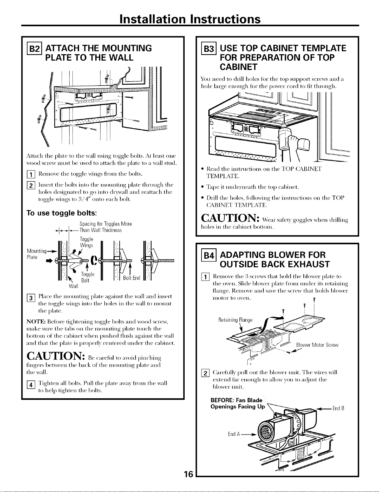
FB--_ATTACH THE MOUNTING
PLATE TO THE WALL
i = il
::::::::i
Attach the plate to the wall using toggle bolts. At least one
wood screw must be used to attach the plate to a wall stud.
_ Remme the toggle wings fi'om the bolts.
_] Insert the bolts into the motmting plate through the
holes designated to go into drywall, and reattach the
toggle wings to 3/4" onto each bolt.
To use toggle bolts:
Spacingfor TogglesMore
_*--_-[_,_Than Wall Thickness
= Toggle
Wings
Mounting.-->_
Plate
VB-3-]USE TOP CABINET TEMPLATE
FOR PREPARATION OF TOP
CABINET
Ym need to drill holes for the top support screws and a
hole large enough t0r the power cord to fit through.
• Read the instructions on the TOP CABINET
TEMPI ATE.
• Tape it underneath the top cabinet.
• Drill the holes, tollowing the instructions on the TOP
CABINETTEMPI ATE.
CAUTION: d, .in
holes in the cabinet bottom.
VB--_ADAPTING BLOWER FOR
OUTSIDE BACK EXHAUST
Bolt
Wall
[_ Place the mounting plate against the wall and insert
the toggle wings into the holes in the wall to motmt
the plate.
NOTE: Before tightening toggle bolts and wood scrm_;
make sure the tabs on the mounting plate touch the
bottom oI the cabinet when pushed flush against the wall
and that the plate is properly centered under the cabinet.
CAUTION: Bec .ef.1 pinching
finge_ between the back of the motmfing plate and
the wall.
[4] Tighten all bolts. Pull the plate axvav fl'om the wall
to help tighten the bolts.
_ Remove the 3 that hold the blower to
the o;en. Slide blower plate from under its retaining
flan ,e Remoxe and saxe the screw that holds blower
II/OtoI" to ox, eil.
sciews
plate
@_10_er MotorScre_
%j_ ...._,.--"
[2] Carefiflly pull out the blower unit. The wires will
extend en- enough to allow xou to at!just the
bl(mer unit.
BEFORE: Fan Blade
Facing Up
Openings _nd B
EndA-_-_ I
16
Page 17

Installation Instructions
_] (;enfly tile wires fl'(nn tile Reroute
WiresRoutedThroughRightSide Wires RoutedThroughLeft Side
[_] Rotate blower unit counterclockwise 180°
i'ei//ove
the wires through grooxes on other side of the
blower unit.
Before Rerouting After Rerouting
BeforeRotation After Rotation
gi'oox es.
Backof Oven
_] Place the blower unit back into tile oi)ening,.
AFTER: Fan Blade
Openings Facing Back
EndB._>-
CAUTION: Do not pull or stretch the blower
unit wiring, Make sure the wires axe not pinched,
NOTE: The blower trait exhaust openings should match
exhaust openhigs on rear of oven.
_] Secure tile blower trait to tile oven with tile screw
_emoved earlier: Replace tile blower plato in tile same
position as before with tile screws.
Retaining g
Flange 2 i
) II BlowerPlate
_] Roll tile blower trait 90 ° that tim blade openings
are ti_cing out the back of the oxen.
BeforeRolling After Rolling
Backof Oven
_] I,ocate tile 2 "knockout" plates, on tile rear oxen
panel, near tile top of tile oxen.
Using tin snips, carefifllv cut tile web area fl'om tile
2 holes side-by-side (that secm'e the knockouts to the
oven). Cut all 4 webs on both rear knockouts; this will
allow the ventilation tim airflow to exhaust out the
i'eai" of tile o'_ eil.
Oven Rear Panel
S
so
Backof Oven
Snipall 4webs
on eachknockout
panelandremove
the metalknockouts
for rearairflow.
_,_ Screw
VB-5 MOUNT THE OVEN
FOR EASIER INS%M.IATION AND PERSONAl. SM,_ETY,
X._ERECOMMEND THAT TWO PEOPLE INSTALL
THIS OVEN.
IMPORTANT: Do not grip or use hmldle during
installation,
NOTE: If w)m" cabinet is metal, use tile m'lon grommet
aro/md tile power cord hole to prevent cutting ot tile cord.
NOTE: We recoi/li/lend rising filler blocks it tile cabinet
fl'ont hangs below tile cabinet bottom shelfi
IMPORTANT: If ftller blocks are not used, case dm_rmge
may occur from over tightenh_g screws.
CAUTION: Be sure to trim the sharp edges
from the openings after removh_g the knockout plates.
17
Page 18

Installation Instructions
MOUNT THE OVEN (cont.)
NOTE: When mounting the oven,
thread power cord through hole
in bottom ot top cabinet. Kee I) it
fight throughout Steps 1-3.
Do not pinch cord or lift oven
b) pulling cord.
_] Rotate _wen u l)
_] Insert a self:aligning screw through top center cabinet
If yore" cabinet fl'ont hangs more than 2_A" below the
cabinet bottom, you may need to use longer screws than
the ones provided with this product. The scre_vs provided
with this product (hardware imm 3) are self:aligning,
lmge-head machine screws 1/4" diamem_; 3¼" long,
with SAE 28 threads per inch. It is important that you
use replacement screws just long enough to attach the
product to the cabinet. The length can be detemfined
by measmJng the height ot the overhang fl'om the top
of the cabinet floor to the bottom of the overhang and
adding l" to that length. This will be the length of the
1/4" SAE 28 threads per inch scrmvs you need.
Ybu will also need to use washe_ 3/4" diameter to fit the
scrmvs wm pro'chase. This will prevent the screw heads
fl'om pulling through the bottom of the cabinet when
tightening dtwing installation.
front OJ[
against cabinet bottom.
hole. Temporarily secm'e the oven by turning the
screw at least two full turns alter the threads have
engaged. (It will be completely tightened late_:)
Be sure to keep power cord tight. Be careful not to
pinch the cord, especially when mounting flush to
bottom of cabinet.
[]i Jfi oven, tilt it
_ forward, and
/ hook slots at back
bottom edge onto
2 lower tabs of
_ mortaring plate.
Cabinet Front
Cabinet Bottom Shelf
Filler Block
T quivalent
to Depth
of Cabinet
Recess
gning Screw
OvenTop
r4] Attach the o_en to the top cabinet.
_] Insert 2 self=aligning screws through outer top cabinet
holes. Turn two flfll turns on each screw.
[]Tighten center
screw completely.
Tighten the outer 2 screws to the top of the oven.
[]
(X._qfiletightening screws, hold the oxen in place
against the wall and the top cabinet.)
Install grease filte_s.
[]
See the Owner's Manual
packed with the oven.
Remove the tape fl'om the
cooktop lalllp covelB on
the bottom of the oven.
Secm'e the power cord to the cabinet wall, as desired
[]
to kee I) excess length out of the way using the power
cord strap and the black metal screw,
_....mJ.
18
Page 19

Installation Instructions
RECIRCULATING (Non-Vented Ductless)
INSTALLATION OVERVIEW
C1. Mmch Mounting Plate to _4"dl
C2. Prepare Top Cabinet
C3. A(!iust Blower
C4. Mount the (-)\'en
C5. Install Charcoal Filter
]-€-_ ATTACH THE MOUNTING
PLATE TO THE WALL
Attach the plate to the wall using toggle bolts. At least one
wood screw must be used to attach the plate to a wall stud.
[_ Remoxe the toggle wings fl'om the bolts.
_] Insert the bolts into the mounting plate through the
holes designated to go into drywall, and reattach the
toggle wings to 3/4" onto each bolt.
To use toggle bolts:
Spacingfor TogglesMore
+]_--_]_._Than Wall Thickness
= Toggle
Wings
Mounting---_
Plate
NOTE: Befi)re tightening toggle bolts and wood scre_;
make sure the tabs on the mounting plate touch the
bottom of the cabinet when pushed flush against the wall
and that the plate is properly centered under the cabinet.
CAUTION: )inchinotinge,s
between the back ot the mounting plate and the wall.
_] Tighten all bolts. Pull the plate awa) fl'om the wall
to help tighten the bolts.
]-€--_USE TOP CABINET TEMPLATE
FOR PREPARATION OF TOP
CABINET
You need to (h_ll holes fin" the top support screws and a
hole large enough fin" the power cord to fit throu ,h
" Read the instrucdons on the TOP CABINET
TEMPI ATE.
Bolt
Wall
_] Place the mounting plate against the wall and insert
the toggle wings into the holes in the wall to mount
the plate.
• Tape it underneath the top cabinet.
• Drill the holes, tollowing the instructions on the TOP
CABINET TEMPLATE.
CAUTION:
holes in the cabinet bottom.
Page 20

Installation Instructions
[-C--_ADAPTING BLOWER FOR
RECIRCULATION
NOTE: Tile exhaust adaptor with damper is not needed
tor recirculating models. Y_m mm want to sa_e them tor
possible fllture use.
_ Remoxe and saxe screws that hold tile blower plate
to tile oxen.
Retaining
Flange _' i
_' \ I I BlowerPlate
___j I[ je IBack OfOven
_-] Slide tile blower plate fl'om trader its retaining flange
and 1N it off. Remme and saxe screw that holds tile
blower ii/otoi" to o_en.
,_<[-_ Blower Plate Screws
_Roll tile blower trait 90 ° so that tim blade openings
are lacing toward tile fl'ont of tile oxen.
BEFORE: Fan Blade
Openings Facing_
R011 4_
AFTER: Fan Blade
Openings Facing _"----.-...._
RetainingFlange __BIo!er
_7 _._ BlowerMotor
Screw
[_ Careflfll) pull out tile blower trait. Tile wires will
extend fin"enough to allow )ou to a(!iust tile
blower trait.
Forward
NOTE: Make sure wires remain routed in tile grooxes of
the Illotor fKlI/le,
_] Place tile blower trait back into tile oi)ening,.
CAUTION: Donoti,/,llstretchtileblower
trait wiring. Make sure tile wires are not pinched.
2O
Page 21

Installation Instructions
_] Secure blower unit to oxen with the screw remoxed
in Step 2.
F7] Replace blower plate with the screws remoxed
in Step 1.
Retaining
Flange _'
_,_---Blower PlateScrews
_ BlowerPlate
_ •
_._ Backof Oven
"_-_-- Blower Motor
Screw
I-C- MOUNT THE OVEN
FOR EASIER INS%MLA, TION AND PERSONAL SMCETY,
X4'ERECOMMEND THAT TWO PEOPLE INSTALL
THIS OVEN.
IMPORTANT: Do not grip or use hm_dle during
h_staJlation.
NOTE: If w)m" cabinet is metal, use the nylon grommet
around the power cord hole to prevent cutting oI the cord.
NOTE: _e recommend using filler blocks if the cabinet
fl'ont hangs below the cabinet bottom shel£
IMPORTANT: If f'filer blocks axe not used, case dmnage
may occur from over tightenh_g screws.
NOTE: X,_q_enmotmting the oven,
thread power cord through hole
in bottom of top cabinet. Kee I) it
tight throughout Steps 1-3.
Do not pinch cord or lift oven
by pulling
[]
Rotate fl'ont _ff oven up
against cabinet bottom.
[]
Insert a self aligning screw through top center cabinet
hole. Temporarily secme the oven by tm'ning the
screw at least two full tur_s alter the threads have
engaged. (It will be completely tightened late_:)
Be sure to keep power cord tight. Be careful not to
pinch the cord, espedaJly when momathag flush to
bottom of cabinet.
If your cabinet fl'ont hangs more than 2:"A"below the
cabinet bottom, you may need to use longer screws than
the ones provided with this product. The screws provided
with this product (hardware item 3) are self:aligning,
lmge-head machine screws 1/4" diameter; 3¼" long,
with SAE 28 threads per inch. It is impommt that you
use replacement screws just long enough m attach the
product to the cabinet. The length can be detemfined
by measuring the height ot the overhang fl'om the top
of the cabinet floor to the bottom of the overhang and
adding l" to that length. This will be the length ot the
1/4" SAE 98 threads per inch screws w)u need.
You will also need to use washers 3/4" diameter to fit the
scre_:s wm l)m'chase. This will prevent the screw heads
fl'om pulling through the bottom ot the cabinet when
tightening dm-ing installation.
[_I,ifl flit it
oven,
torward, and
hook slots at back
bott()n} edge onto
2 lower tabs ot
inounfing plato.
21
Page 22

Installation Instructions
I-€--_MOUNT THE OVEN (cont.)
Cabinet Front
Cabinet Bottom Shelf
Filler Block
T quivalent
to Depth
of Cabinet
Recess
gningScrew
OvenTop
_ Attnch the o_en to the top cabinet.
_] Insert 2 self:aligning screws through outer top cabinet
holes. Turn two fl/ll turns on each screw.
VC--_INSTALLING THE CHARCOAL
FILTER
[] Remo'_e 2 ,_ci'ews on top of grille using a Phillips
screwdriver: You may need to open the cabinet doo_s
1o i'eillo&e the scI'ews,
_] Open the dora:
[] Remme the
[z[-] ]nstnll the charcoal filte_; _,_hen propefl) installed,
the wire mesh of the filter should be visible fl'om
the fl'ont,
[] Replace the grille and the 9 screws,
[_ Close the dora:
S
grille.
_] Tighten center
screw completely.
F7-] Tighten the outer 2 screws to the top of the o_en.
(_4_file tightening screws, hoM the o_en in place
against the wall and the top cabinet.)
_-] ]nstnll grease filte_.
See the Owner's Manual
packed with the oven.
Remove the tape fl'om the
cooktop lalllp covels on
the bottom of the oven.
_] Secure the power cord to the cabinet wall, as desired
to kee I) excess length out of the way, using, the l)°wer
cord strap and the black metnl screw.
......................//
Insert mesh-side down
22
Page 23

Installation Instructions
BEFORE YOU USE YOUR OVEN
_Make the has been installed according to
I [] Remo_e all packing material fl'om the o_en.
I [] Install o_en rack (mrntnble) in cavity.
[] Replace house fllse or mrn breaker back on.
Stli'e oxen
instructions.
IllIIIIIIII
_] Read the Owner's Manual.
[_ KEEP INSTAI,LATION INSTRUCTIONS FOR THE
I
I,OCAI, INSPECTOR _ USE.
J
f
I
L............-----_
_] Plug cord into dedicated NEMA 14-30Rpower
wall receptncle.
Insureproper
groundexists
beforeuse.
Wall Receptacle
NEMA14-30R
23
Page 24

164D3370P269
49-40339-1
3828W5U0315
o7-o3JR
Printed in Korea
 Loading...