

Page 1
g
GE Consumer Service Training
TECHNICAL SERVICE GUIDE
ADVANTIUM™ SPEEDCOOKING
MODEL SERIES:
GE Profile Performance™
SCA2000BAA
SCA2000BBB
SCA2000BCC
SCA2000BWW
SCA2001BSS
TM
PUB # 31-9038 10/99
Page 2

!
IMPORTANT SAFETY NOTICE
The information in this service guide is intended
for use by individuals possessing adequate
backgrounds of electrical, electronic and
mechanical experience. Any attempt to repair a
major appliance may result in personal injury and
property damage. The manufacturer or seller
cannot be responsible for the interpretation of this
information, nor can it assume any liability in
connection with its use.
CAUTION
To avoid personal injury while servicing this unit,
disconnect power before servicing. If grounding
wires, screws, straps, clips, nuts, or washers used
to complete a path to ground are removed for
service, they must be returned to their original
position and properly fastened.
GE Consumer Service Training
Technician Service Guide
Copyright © 1999
All rights reserved. This service guide may not be reproduced in whole or in part
in any form without written permission from the General Electric Company.
Page 3
TABLE OF CONTENTS
Welcome to Advantium
Installation Instructions
Specifications
Warranty
Overview of Advantium
Control Panel Features
Cooking Guide
How to Speedcook
Operating Characteristics Index
Mechanical Disassembly Index
2
4
14
15
16
17
18
22
23
33
Troubleshooting Index
Illustrated Parts Breakdown
Six Sigma - What is it?
Last Minute Additions - Addendum
45
56
58
59
42
43
43
44
TM
– 1 –
Page 4
WELCOME TO
TM
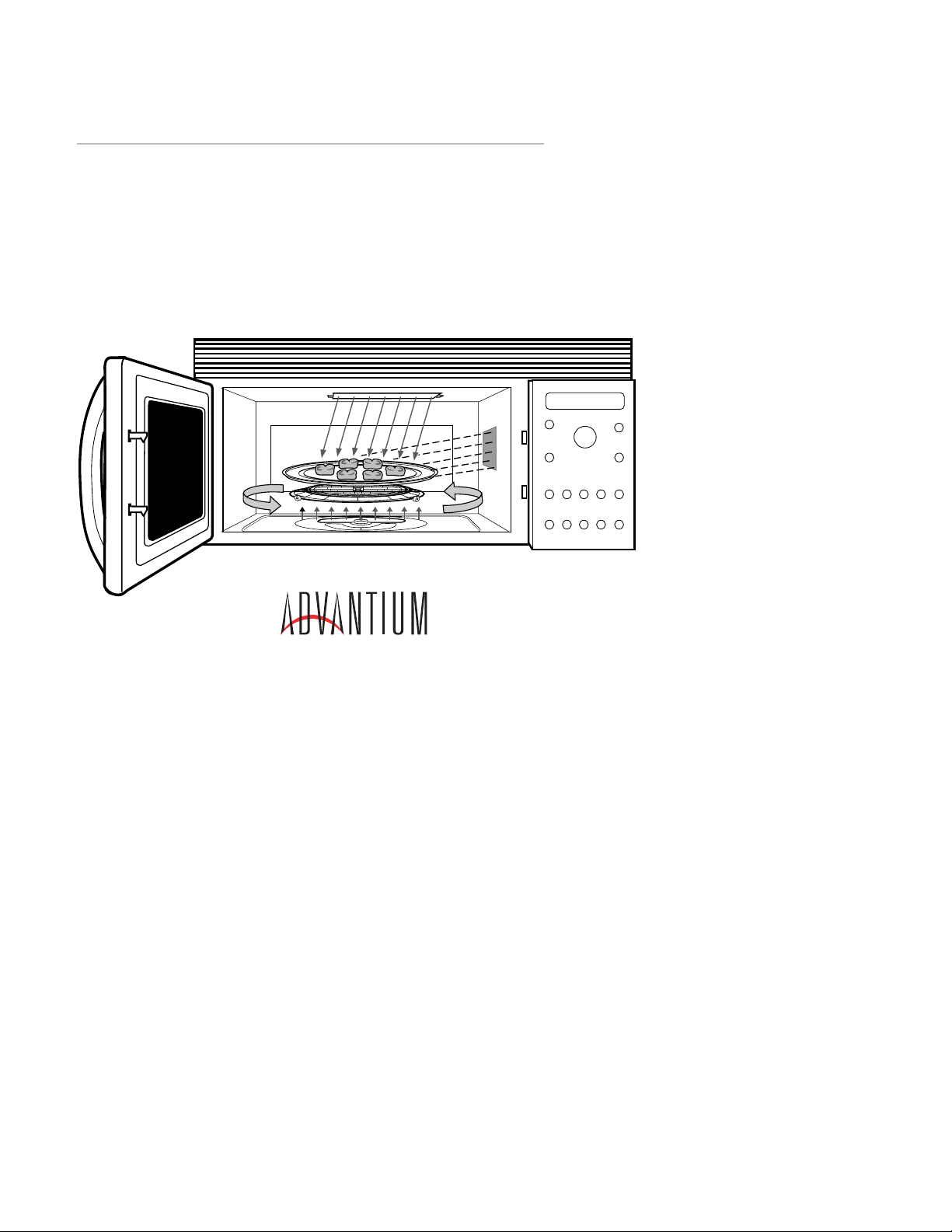
The new Advantium™ oven uses breakthrough
Speedcook technology to cook food with light.
Foods cook in a fraction of the time needed in
conventional ovens with delicious results.
Advantium browns, bakes, roasts, broils and
crisps just like a conventional ov en, and requires
no preheating. Advantium uses high intensity
halogen lights to cook food from the top and bottom simultaneously, cooking the surface and interior to seal in moisture and flavor. For added
convenience, the Advantium oven can be converted to a fully functional microwave by simply
pressing a button.
the type and size of food. Also be sure to consult
the front of the cookbook for proper cookware
selection and food placement on the turntable
Pub. No. 49-40070
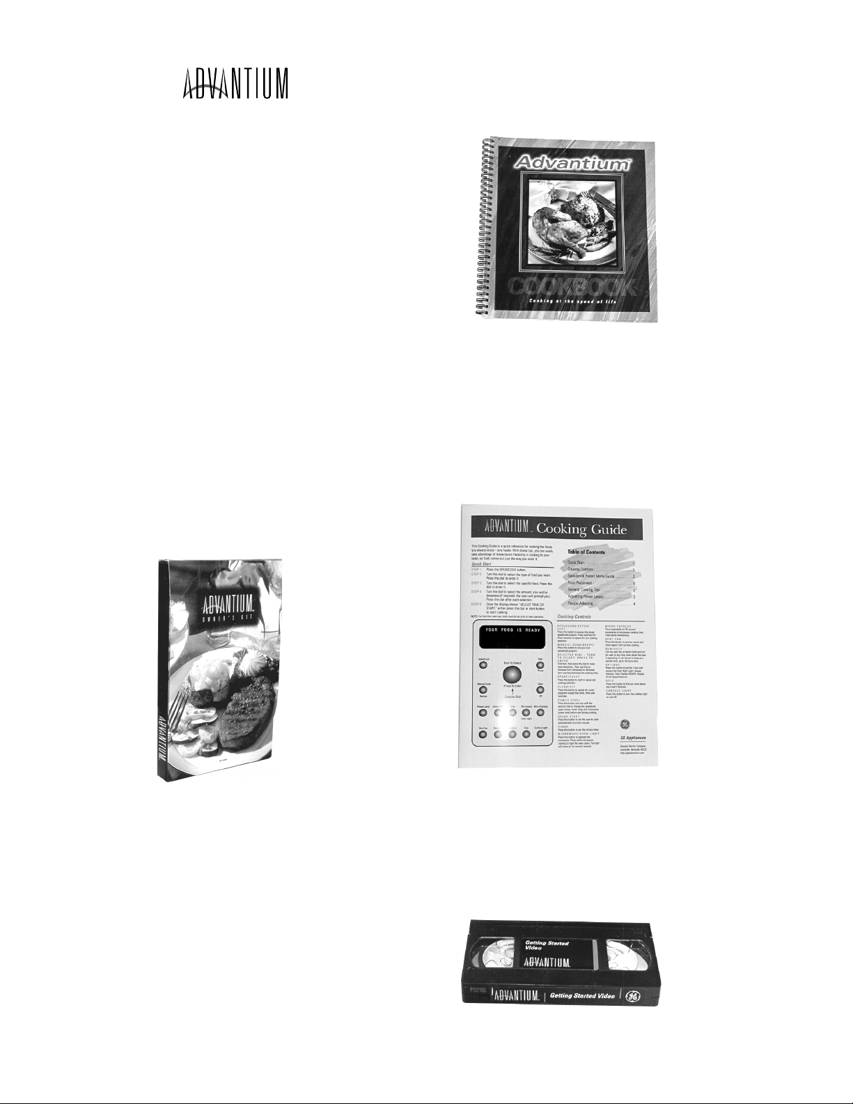
Advantium™ Owners Kit
Included with the purchase of the Advantium™
oven is an Advantium™ Owners Kit. The kit includes
the following helpful tools and literature:
1. 135 page cookbook
2. 4 page cooking guide
3. Owner’s manual (use & care guide)
4. “Getting Started” Video (17:37 mins)
5. Cleaning Scraper
Cooking Guide
The cooking guide is a 4 page, quick reference
guide containing numerous helpful cooking tips.
In addition it contains helpful use and care information and 2 pages of information which will assist the consumer in adapting their favorite recipe
for the Advantium oven.
Pub. No. 49-40095
Pub. No. 28-X139
Cookbook
The cookbook includes numerous recipes, helpful cooking tips, information on proper cooking
techniques, and proper use of cookware for v arious types of recipes. The cookbook is also a
helpful diagnostic tool when servicing an
Advantium™ oven for a cooking issue. Be sure
to reference the cookbook prior to servicing a
unit for any cooking concern. Be sure that the
customer is following the proper selections for
“Getting Started” Video (17:37 mins)
The “Getting Started” video provides general information on proper use and care, and is intended
to help the consumer during their initial use of
the product (getting started).
Pub. No. 28-X129
– 2 –
Page 5
Owners Manual
The owners manual provides the customer with
detailed information on the operation, use and
care of their product. It also contains a section
on helpful troubleshooting tips.
GE Appliances
Other Features . . . . .32–35
Auto night light . . . . . . . . . . . . . .32
Automatic fan . . . . . . . . . . . . . . .35
Beeper volume . . . . . . . . . . . . . . .32
Child lockout . . . . . . . . . . . . . . . .35
Clock . . . . . . . . . . . . . . . . . . .10, 32
Delay start . . . . . . . . . . . . . . . . . .34
Display . . . . . . . . . . . . . . . . . . . .32
Help . . . . . . . . . . . . . . . . . . . . . .33
Reminder . . . . . . . . . . . . . . . . . .34
Review . . . . . . . . . . . . . . . . . . . .32
Scroll speed . . . . . . . . . . . . . . . . .32
Surface light . . . . . . . . . . . . . . . .35
Timer . . . . . . . . . . . . . . . . . . . . .34
Vent fan . . . . . . . . . . . . . . . . . . .35
Care and Cleaning .36–40
Cleaning the inside . . . . . . . .36–37
Cleaning the outside . . . . . . . . . .38
Filters . . . . . . . . . . . . . . . . . .39–40
Lamp covers . . . . . . . . . . . . . . . .37
Optional accessories . . . . . . . . . . .40
Replacing lights . . . . . . . . . . . . . .38
Troubleshooting . . .41, 42
Problem Solver . . . . . . . . . . . .41, 42
Customer Service
Customer information . . . . . . . .2, 8
Service phone numbers . .Back Cover
Warranty . . . . . . . . . . . . . . . . . .47
Part No. 164D3370P067-1 Pub. No. 49-40067-1 8-99 JR
Owner's Manual
SCA2000
SCA2001
Pub. No. 49-40067-1
™
http://geadvantium.com
Advantium . . . . . . . . .2–13
Advantium Quick Start . . . . . . . .10
Cooking controls . . . . . . . . . . . . .13
Customer information . . . . . . . . . .8
Oven features . . . . . . . . . . . . . . .12
Getting to know Advantium . . . . .9
Speedcook Menu Guide . . . . . . . .11
Safety . . . . . . . . . . . . . . . . . . . . .2–7
Speedcooking . . . . . .14–21
Cooking tips . . . . . . . . . . . . . . . . .15
Custom speedcook recipe log . . . . .21
Manual speedcook . . . . . . . . . . . .17
Power level . . . . . . . . . . . . . . . . . .16
Repeat last . . . . . . . . . . . . . . . . . .15
Resume feature . . . . . . . . . . . . . .15
Oven
Review . . . . . . . . . . . . . . . . . . . .17
Speedcook cookware . . . . . . . . . . .17
Speedcook-safe cookware . . . . . . . . .5
Storing custom
speedcook recipes . . . . . . . . . .18–19
Things that are normal . . . . . . . .20
Using a pre-set speedcook menu . .14
Microwaving . . . . . .22–31
Cooking tips . . . . . . . . . . . . . . . .23
Custom microwave recipe log . . . .31
Defrost (auto) . . . . . . . . . . . . . . .26
Defrost (time) . . . . . . . . . . . . . . . .26
Defrosting tips . . . . . . . . . . . . . . .27
Micro Express . . . . . . . . . . . . . . .23
Microwave power levels . . . . . . . .23
Microwave-safe cookware . . . . . . . .6
Precautions to avoid possible
exposure to microwave energy . . . . .2
Review . . . . . . . . . . . . . . . . . . . .29
Sensor cooking . . . . . . . . . . . .28–29
Storing custom
microwave recipes . . . . . . . . .24–25
Things that are normal . . . . . . . .30
Time cook . . . . . . . . . . . . . . . . . .22
Using pre-set
microwave selections . . . . . . . . . .22
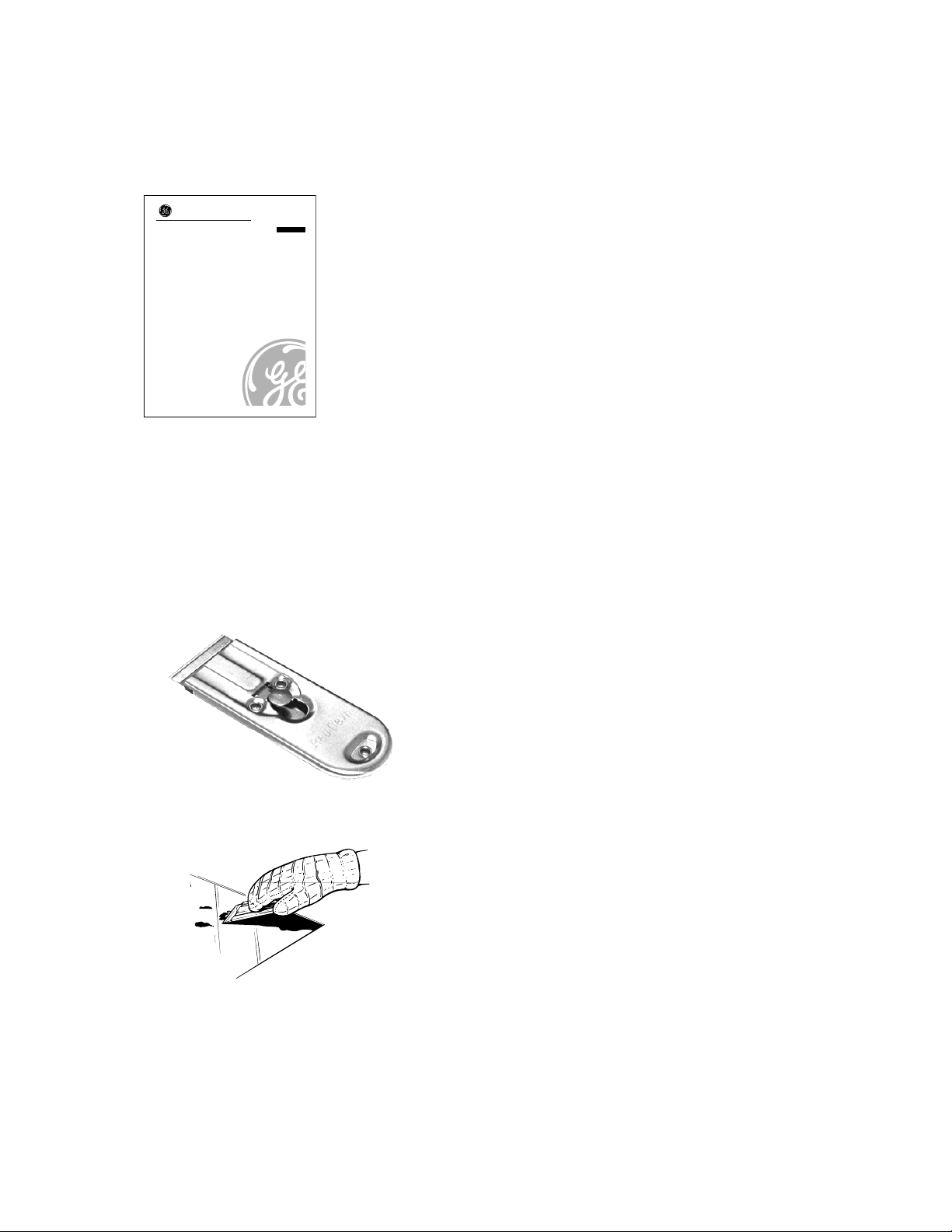
Advantium
Scraper/Cleaner
The last item included in the Advantium™ Owners kit is a Scraper/Cleaner . This tool is included
in order to aid the consumer in cleaning the upper and lower halogen lamp cov ers. These covers must be kept clean in order to ensure maximum cooking efficiency.
WX5X1614
For heavy or burned on soil
– 3 –
Page 6

INSTALLATION INSTRUCTIONS
IMPORTANT – PLEASE READ CAREFULLY.
FOR PERSONAL SAFETY, THIS APPLIANCE
MUST
BE PROPERLY GROUNDED TO
AVOID SEVERE OR FATAL SHOCK.
1
REQUIREMENTS FOR INSTALLATION
Important Safety Instructions
See electrical requirements for proper outlet
installation and grounding of this appliance. The
installer must perform a ground continuity check
on the power outlet box before beginning the
installation to insure the outlet box is properly
grounded. If not properly grounded, or if the
outlet does not meet electrical requirements noted
below, a qualified electrician should be employed
to correct any deficiencies.
CAUTION: For personal safety, remove house
fuse or open the circuit breaker before
beginning installation.
CAUTION: For personal safety, the mounting
surface must be capable of supporting the
cabinet load in addition to the added weight
of this 70 lb. product plus oven loads of up
to 50 lbs., or a total of 120 lbs.
CAUTION: For personal safety, this product
cannot be installed in cabinet arrangements
such as an island or a peninsula. It must be
mounted to both a top cabinet and a wall.
NOTE: For easier installation and personal safety,
it is recommended that two persons install this
product.
Fig. 1
Insure proper
ground exists
before use.
NEMA 14-30R
Wall Receptacle
DO NOT UNDER ANY CIRCUMSTANCES,
CUT, DEFORM, OR REMOVE ANY OF THE
PRONGS FROM THE POWER CORD. DO NOT
USE WITH AN EXTENSION CORD.
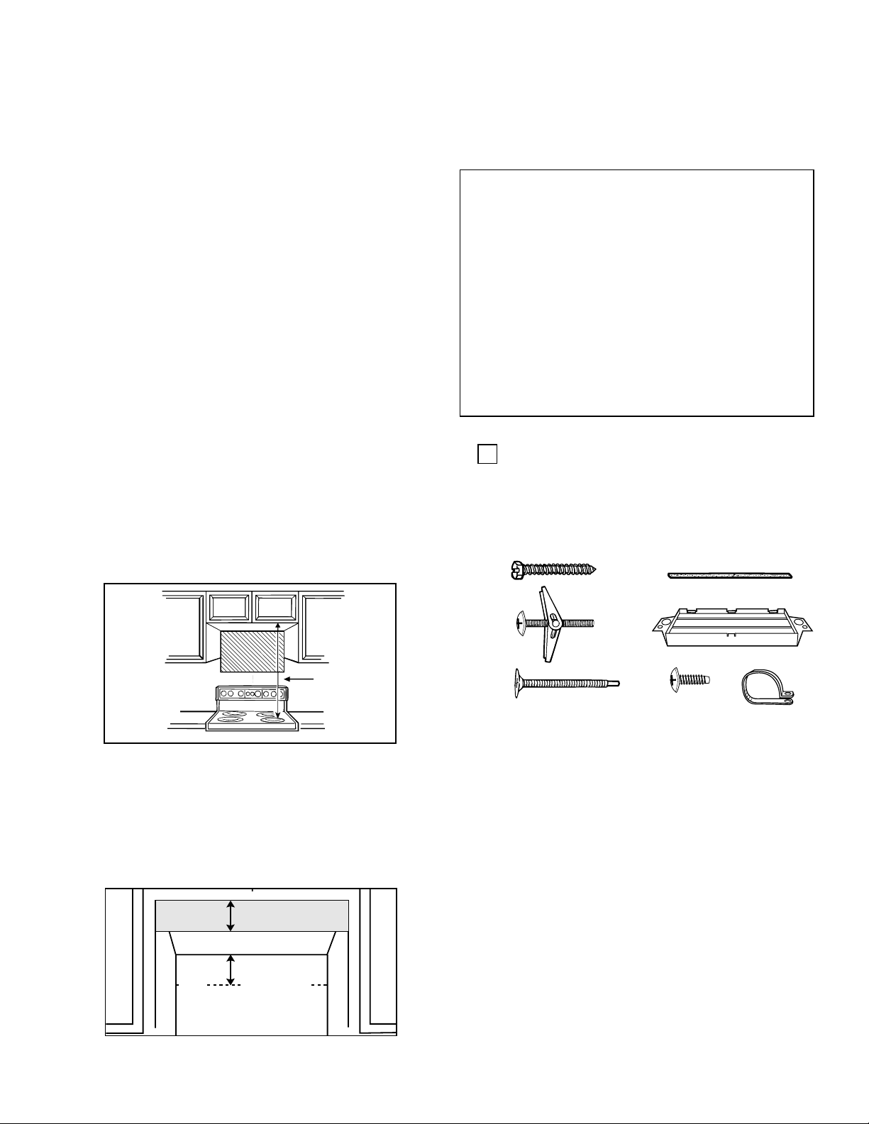
Mounting Space
This section describes the space you need to install
your oven.
Your oven requires mounting space on a wall
as shown.
Bottom Edge
of Cabinet
Needs to be
30″ or More
From the
Cooking
Surface
Backsplash
16-1/8″
30″
2″
30″
66″ or More
From the
Floor to the
Top of the
Oven
Electrical Requirements
Product rating is 240/208 volts AC, 60 Hertz,
30 amps and 6.5 kilowatts. This product must be
connected to an individual properly grounded
branch circuit, protected by circuit breakers or
time delay fuses. Wire size must conform to the
requirements of the National Electric Code or the
prevailing local code for this kilowatt rating. The
outlet box should be located in the cabinet above
the oven. The supply circuit and outlet box should
be installed by a qualified electrician and conform
to all prevailing electrical codes. The wall outlet
receptacle recommended for this appliance is
NEMA # 14-30R and accepts the four prong
grounded plug of this appliance (see Fig. 1 above).
1. A minimum of 30″ between the cabinets is
required for installation. If the space between
the cabinets is greater than 30″, a Filler Panel
Kit may be used to fill in the gap between the
oven and the cabinets. Your Owner's Manual
contains the kit number for your model.
2. Make sure the bottom edge of the cabinet that
will be above the oven is at least 66″ from the
floor and 30″ from the cooking surface.
3. For easier access to change the hood and range
lamps, the bottom of the oven should be at least
2″above the range backsplash.
4. If you are going to vent your oven to the outside,
see Section 5 for exhaust duct preparation.
5. When installing the oven beneath smooth,
flat cabinets, be careful to follow the
instructions on the top cabinet template for
power cord clearance.
6. For best installation results, we recommend a
maximum cabinet depth of 12″.
– 4 –
Page 7
OVERVIEW OF INSTALLATION PROCEDURE
This section gives a brief overview of what you
need to do to install this oven. Read these entire
instructions before you begin installation.
Before you install this oven, remove the adhesive
tape, if there is any, on the exhaust adaptor,
grease filters and power supply cord.
1. Install an outlet and make sure you meet the
electrical requirements for this installation.
2. Open the installation hardware packets.
Compare it to the hardware list to make sure
you have all the parts.
3. Remove the mounting plate.
4. Check the oven exhaust duct and change it if
required.
5. Attach the mounting plate to the wall.
Your cabinets may have trim that interferes
with the oven installation. You may need to
remove the trim in order to fit the oven in
and to make it level.
The space must be 30″ wide. Remove any
cabinet side trim that interferes with the 30″
space, front or back.
THE OVEN MUST BE LEVEL.
If the cabinets have top trim (front, back or
both), this can be left in place if there is still
enough clearance for proper installation.
6. Hook the slots at the back bottom edge of the
oven onto the 2 lower tabs of the mounting
plate and rotate it up.
7. Attach the oven to the top cabinet.
TOOLS YOU WILL NEED
• Phillips screwdriver
• Pencil
• Ruler or tape measure and straight edge
• Carpenter square (optional)
• Tin snips (in some applications)
• Electric drill with 3/16″, 1/2″ & 5/8 ″ drill bits
• Hammer
• Stud finder (optional)
• Filler blocks, if needed for top cabinet spacing
• Gloves
• Saw (jig or keyhole)
2
PARTS INCLUDED
You will find the installation hardware packed
with the unit. Check to make sure you have all
these parts. The installation hardware (1–7)
should include the following:
1
4
30″
If you leave the top front trim on, and there is
no back trim, make sure the mounting plate
is positioned down far enough to keep the
oven level. Keep the space between the
bottom of the cabinet and the mounting plate
equal to the height of the top front trim. This
will insure level installation of the oven.
Height of the
Top Front Trim
Mounting
Back
Wall
plate must
be installed
so that the
oven
is level
5
2
3
6
7
Hardware List Qty
(some extra parts are included)
1. Wood Screws (1/4″ x 2″) 2
2. Toggle Bolts (and wing nuts) 4
1/4″ x 3″
3. Self-aligning Machine Screws
(1/4″ x 3
1
/4″) 3
4. Nylon Grommet (for metal cabinets) 2
5. Exhaust Adaptor (with damper) 1
6. Metal Screws (1/8” x 1/2”) 3
(1 black, 2 bronze)
7. Power Cord Strap (plastic) 1
In addition you will need:
Top Cabinet Template 1
Installation Instructions 1
Separately Packed Grease Filters 2
– 5 –
Page 8

3
HOOD EXHAUST DUCT
Outside ventilation requires a HOOD EXHAUST
DUCT. Read the following carefully.
EXHAUST CONNECTION: The hood exhaust
has been designed to mate with a standard 3
1
?4″
x 10″ rectangular duct.
If a round duct is required, a rectangular-to-round
transition adaptor must be used. Do not use less
than a 6″ diameter duct.
REAR EXHAUST: If a rear or horizontal
exhaust is to be used, care should be taken to
align exhaust with space between studs, or wall
should be prepared at the time it is constructed
by leaving enough space between the wall studs
to accommodate exhaust.
MAXIMUM DUCT LENGTH: For satisfactory
air movement, the total duct length of 3
1
?4″ x 10″
rectangular or 6″ diameter round duct should
not exceed 140 equivalent feet.
ELBOWS, TRANSITIONS, WALL AND
ROOF CAPS, etc., present additional resistance
to airflow and are equivalent to a section of
straight duct which is longer than their actual
physical size. When calculating the total duct
length, add the equivalent lengths of all
transitions and adaptors plus the length of all
straight duct sections. The chart below shows
the approximate feet of equivalent length of
some typical ducts.
A. Rectangular-to-Round
Transition Adaptor
5 Ft.
C. 90˚ Elbow
10 Ft.
E. 90˚ Elbow
25 Ft.
B. Wall Cap
40 Ft.
D. 45˚ Elbow
5 Ft.
F. 45˚ Elbow
5 Ft.
Duct Equivalent Length
A. Rectangular-to-Round
5 Ft.
Transition Adaptor
B. Wall Cap 40 Ft.
C. 90˚ Elbow 10 Ft.
D. 45˚ Elbow 5 Ft.
E. 90˚ Elbow 25 Ft.
F. 45˚ Elbow 5 Ft.
G. Roof Cap 24 Ft.
G. Roof Cap
24 Ft.
– 6 –
Page 9
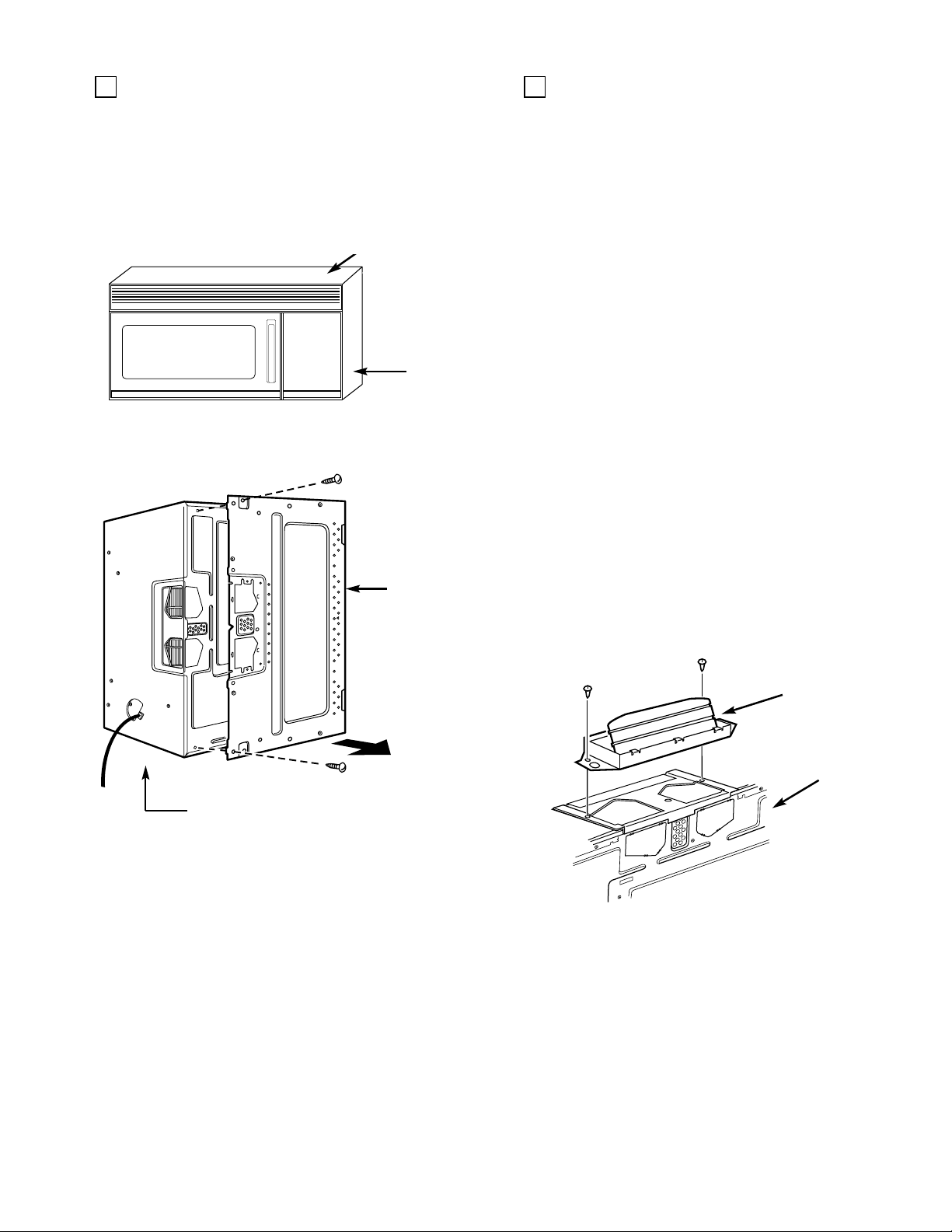
4
REMOVE THE MOUNTING PLATE
The mounting plate comes attached to the
back of the oven.
1. Stand the oven on its control panel side. Use a
portion of the carton or some other material
to protect the outer case from being damaged.
Mounting Plate
Control
Panel
Side
Mounting
Plate
5
OVEN EXHAUST DUCT
This oven is designed for adaptation to the
following three types of ventilation.
NOTE: This oven is shipped assembled for top
exhaust. Select the type of ventilation required
for your installation and proceed to that section.
A. Outside Top Exhaust (Vertical Duct)
B.Outside Back Exhaust (Horizontal Duct)
C. Recirculating (Non-Vented Ductless)
A Charcoal Filter Accessory Kit is required
for the non-vented exhaust. (See your
Owners Manual for the kit number.)
ADAPTING OVEN BLOWER
A. OUTSIDE TOP EXHAUST (Vertical)
This oven is shipped assembled for top exhaust.
However, if you have a recessed cabinet bottom,
you will need to install the exhaust adaptor now.
If you have a flat bottom cabinet, the exhaust
adaptor will be installed later through the cutout
in the cabinet bottom.
For recessed bottomed cabinets only:
1. Remove and discard the 2 screws for the
blower plate.
2. Position the exhaust adaptor (hardware item 5)
over the blower plate, hinge side toward the
back of the oven.
Control Panel Side
2. Remove the 2 screws from the mounting
plate as shown.
3. This plate will be used as the rear wall
template.
4. Locate exhaust adaptor, grease filters and
hardware packet.
5. At this point, remove any adhesive tape
(if there is any), on the exhaust adaptor, the
grease filters and the power supply cord.
Exhaust
Adaptor
Back
of Oven
3. Attach the exhaust adaptor to the blower plate
using the 2 bronze metal screws provided
(hardware item 6).
4. Proceed to the PREPARATION OF TOP
CABINET section.
For flat bottomed cabinets, proceed to the
PREPARATION OF TOP CABINET section.
– 7 –
Page 10
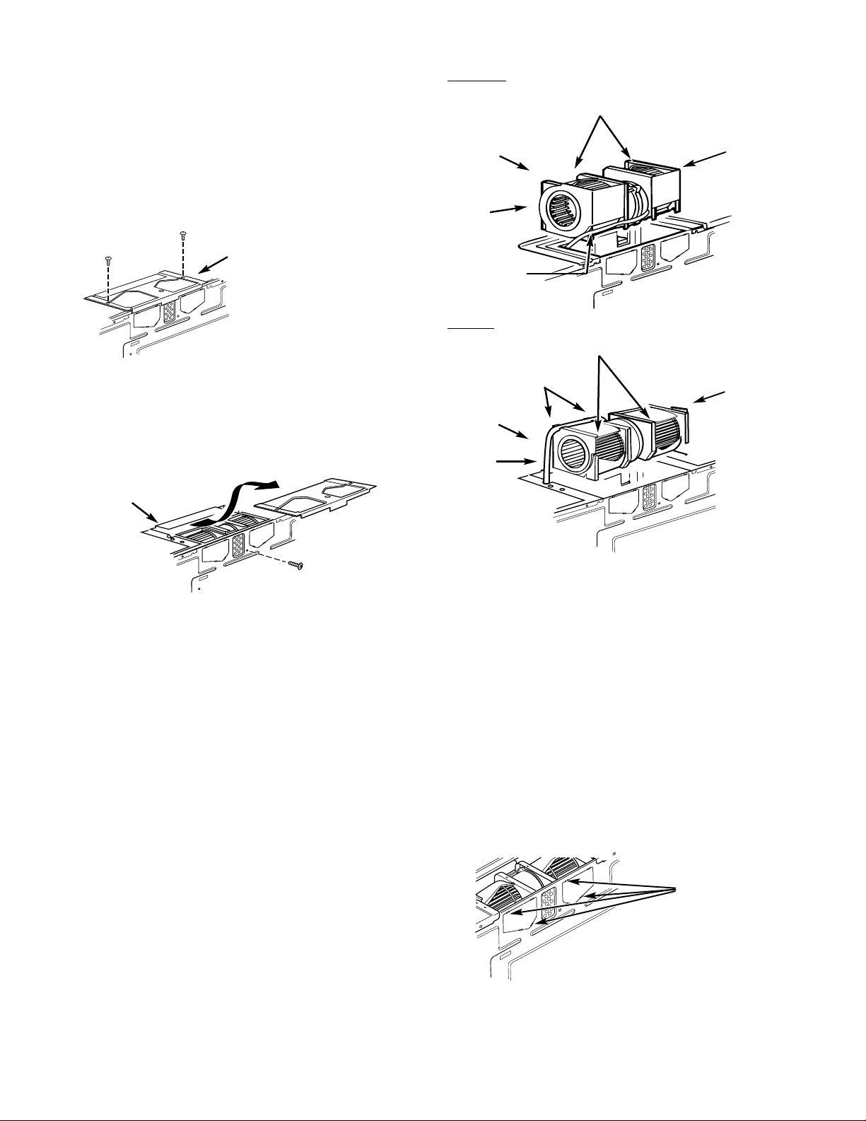
B. OUTSIDE BACK EXHAUST
T
(Horizontal Duct)
his oven is shipped assembled for top exhaust.
Use the following steps to change it for outside
back exhaust.
1. Remove and save the screws that hold the
blower plate to the oven.
BEFORE:
Blower
Unit
End A
Fan Blade Openings Facing Up
End B
2. Slide the blower plate back from under its
retaining flange and lift it off.
• Remove and save the screw that holds the
Blower Plate
Grooves
AFTER:
Fan Blade Openings Facing Back
Grooves
End A
Blower
Unit
blower motor to the oven.
End B
Retaining Flange
• The wires should be routed in the grooves
of the motor frame.
3. • Carefully pull out the blower unit.
4. • Locate the two “knockout” plates, on the
rear oven panel, near the top of the oven.
• The wires will extend far enough
to allow you to adjust the blower unit.
• Turn the blower unit end-over-end.
• Reroute the wires through the grooves on
the other side.
• Roll the blower unit so that the fan
blade openings are facing out the
back of the oven. The blower
unit exhaust openings should match
the exhaust openings on the rear of
the oven.
• Using tin snips, carefully cut the web area
from the two holes side-by-side (that secure
the knockouts to the oven). Cut all four
webs on both rear knockouts; this will allow
the ventilation fan airflow to exhaust out
the rear of the oven.
CAUTION: Be sure to trim the sharp edges
from the openings after removing the
knockout plates.
– 8 –
Oven Rear Panel
Snip all 4 webs
on each knockout
panel and remove
the metal knockouts
for rear airflow.
Page 11

5. • Guide the wires into the duct as you place
the blower unit back into the opening.
• Secure the blower unit to the oven with the
screw from Step 2.
CAUTION: Do not pull or stretch the blower
unit wiring. Make sure the wires are
not pinched.
6. Replace the blower plate in the same position
as before, under its retaining flange, and
attach it with the screws.
7. Proceed to the PREPARATION OF THE
TOP CABINET section.
C. RECIRCULATION
(Non-Vented, Ductless)
NOTE: The exhaust adaptor with damper is not
needed for recirculating models. You may want
to save them for possible future use. (You must
use the Charcoal Filter Kit. See your Owner's
Manual for kit number.)
1. Remove and save the screws that hold the
blower plate to the oven.
2. • Slide the blower plate back from under its
retaining flange and lift it off.
• Remove and save the screw that holds the
blower motor to the oven.
3. Carefully pull out the blower unit. The wires
will extend far enough to allow you to adjust
the blower unit.
• Roll the blower unit so that the fan
blades are facing towards the front
of the oven.
• The wires should be routed in the grooves of
the motor frame.
Blower Plate
BEFORE:
Fan Blade Openings Facing Up
Blower
Unit
AFTER:
Fan Blade Openings Facing Front of Oven
Blower
Unit
Grooves
Grooves
Retaining
Flange
Retaining
Flange
– 9 –
Page 12
5
OVEN EXHAUST DUCT
(continued)
4. • Guide the wires into the duct as you place
the blower unit back into the opening.
• Secure the blower motor to the oven
with the screw from Step 2.
CAUTION: Do not pull or stretch blower unit
wiring. Make sure wires are not pinched.
5. Replace the blower plate in the same position
as before, under its retaining flange, and
attach it with the screws.
Retaining
Flange
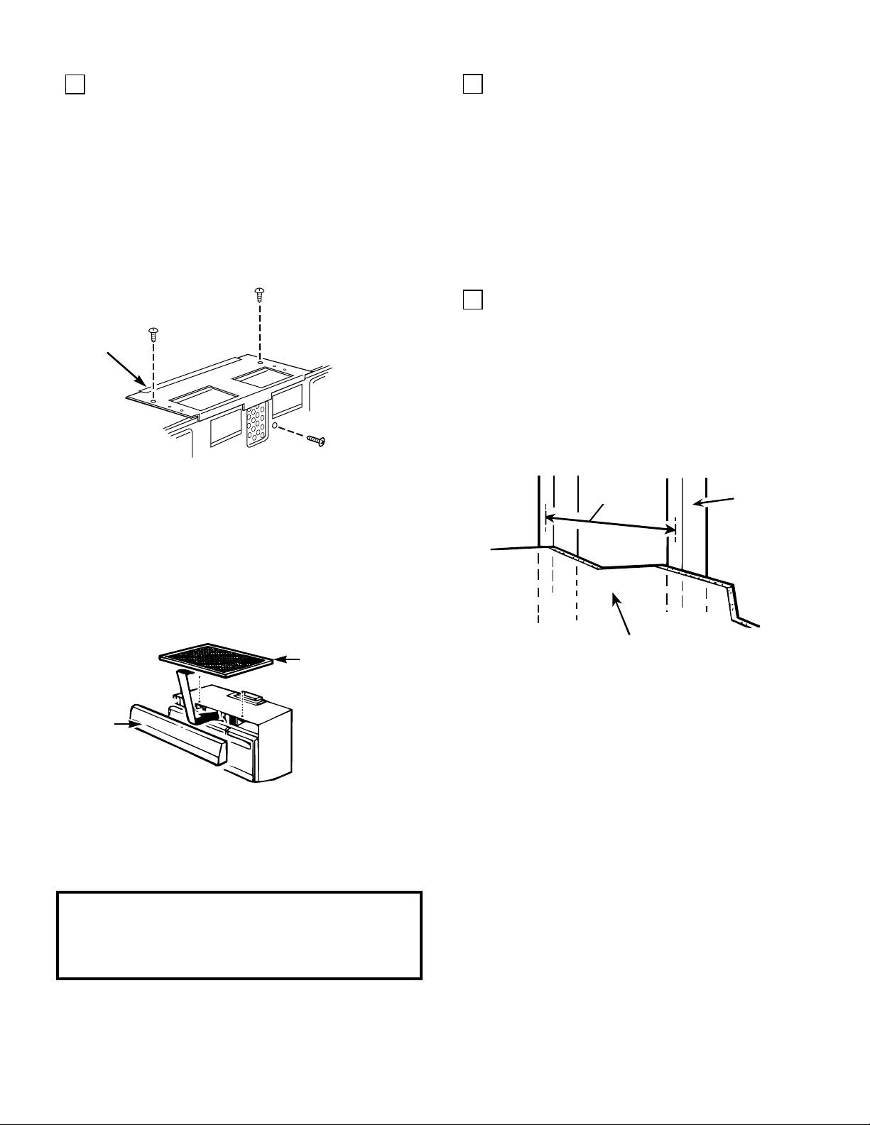
6
PREPARATION OF TOP CABINET
You need to drill holes for the top support
screws and a hole large enough for the power
cord to fit through.
• Read the instructions on the top cabinet
template.
• Tape it underneath the top cabinet.
• Drill and cut out the appropriate holes,
following the instructions on the template.
7
ATTACH THE MOUNTING PLATE
TO THE WALL
Your oven needs to be mounted against and
supported by a flat, vertical wall. Wall
construction should be a minimum of 2″ x 4″ wall
studding and 3/8″ or more thick drywall or
plaster/lath. The oven must be attached to a
minimum of one 2″ x 4″ wall stud.
6. Install the Charcoal Filter. See the Owner's
Manual for the Charcoal Filter Accessory Kit
needed for this model.
• Remove the 2 screws on the top of the case
and remove the grille.
• Install the charcoal filter.
• Replace the grille and 2 screws.
Charcoal Filter
Grille
7. Proceed to the PREPARATION OF TOP
CABINET section.
IMPORTANT—When installing the exhaust
blower in recirculation position, use Charcoal
Filter Accessory Kit available from your
appliance dealer.
Usually
16″ or 24″
Drywall or
Plaster/Lath
2" x 4"
Wall Stud
1. Find the studs, using one of the following
methods:
A. Stud finder—a magnetic device which
locates nails.
B. Use a hammer to tap lightly across the
mounting surface to find a solid sound.
This will indicate a stud installation.
After locating the stud(s), the center can be
found by probing the wall with a small nail to
find the edges of the stud and then placing a
mark halfway between the edges. The center
of any adjacent studs should be 16″ or 24″ from
this mark.
2. Draw a line down the middle of the studs.
THE OVEN MUST BE CONNECTED TO AT
LEAST ONE WALL STUD.
– 10 –
Page 13
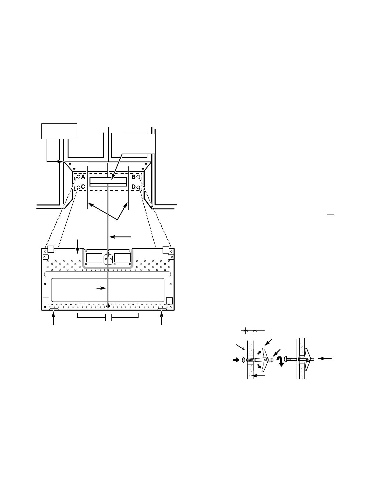
3. Draw a vertical line on the wall at the center
of the 30″ wide space.
Use the mounting plate as the template for
the rear wall. Place the mounting plate on the
wall, making sure that the tabs are against the
bottom of the cabinet. Line up the notch and
center line on the mounting plate to the
center line on the wall.
3/16″Hole on Studs
″
Hole on Drywall Only
5/8
4. While holding the mounting plate with one
hand, draw circles on the wall at holes A, B,
C and D. Four holes must be used for
mounting. If the holes are not used, the
installation will not be secure. Installer
must use these holes for proper
installation. Use toggle bolts through these
holes unless one of them lines up with a stud.
Use a wood screw for studs.
NOTE: Draw a fifth circle inside area E, through
one of the bottom holes to match the location
of a stud.
Minimum 66″
From the Floor
Mounting
A
Center Line
C
Plate
For Outside
Back Exhaust
Only
Draw Lines
on Studs
Draw
Center Line
For outside back exhaust: The oven requires
a rear wall cutout opening for the rear wall duct
and the exhaust adaptor must be attached to
the mounting plate. See the next page on how to
prepare the rear wall cutout opening and the
exhaust adaptor/mounting plate for outside
back exhaust.
Set the mounting plate aside.
5.
Drill holes on the circles. If there is a stud, drill
a 3/16″ hole for wood screws. If there is no
stud, drill a 5/8″ hole for toggle bolts. Make
sure to use at least 1 wood screw in a
stud, and 4 toggle bolts in the drywall or
the plaster.
B
6. Attach the plate to the wall. To use toggle
bolts: Remove the toggle wings from the
bolts. Insert the bolts into the mounting plate
and replace the toggle wings to 3/4″ past the
bolt ends. Insert the toggle wings into the
holes in the wall to mount the bracket. You
may pull forward on the bracket to help in
D
tightening the toggle bolts. Tighten all bolts.
Tab
E
Tab
Mounting
Plate
– 11 –
Space More Than Wall Thickness
Toggle Wings
Toggle Bolt
Bolt
End
Wall
Page 14
7
ATTACH THE MOUNTING PLATE
TO THE WALL
(continued)
To prepare the rear wall cutout opening
and exhaust adaptor/mounting plate for
outside back exhaust:
1. Place the mounting plate against the rear
wall as described in Step 7, item 3.
2. Using a pencil, put dots through slots F
and G, and through holes H and I. Remove
the mounting plate and draw lines
extending through the points. This will
give the location and size of the box cutout
for the rear wall duct.
F
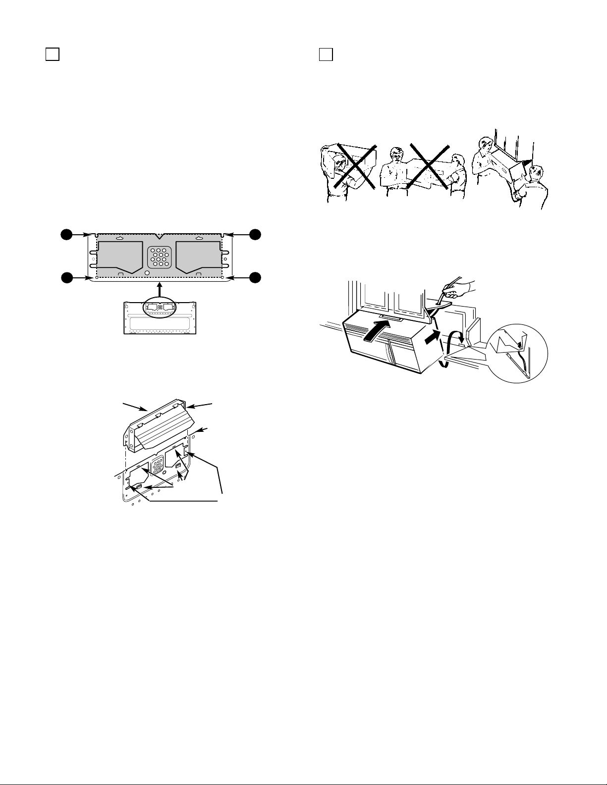
8
MOUNT THE OVEN
FOR EASIER INSTALLATION AND PERSONAL
SAFETY, WE RECOMMEND THAT TWO
PEOPLE INSTALL THIS OVEN.
IMPORTANT: Do not grip or use handle during
installation.
1. Locate the grease filters packed separately
G
and set aside. Thread the power cord through
the hole in the bottom of the top cabinet. Keep
the cord tight throughout Step 2.
H
I
• Attach the exhaust adapter to the rear
mounting plate by sliding it into the guides at
the top center of the plate on the wall side.
Exhaust Adaptor
Slide exhaust
adaptor into
guides on
rear panel.
Locking
Tabs
Damper
(hinge side up)
Mounting Plate
(wall side)
Guides
Push in securely until it is past the top locking
tabs and in the lower locking tabs. Take care to
assure the damper hinge is installed so that it is
at the top and that the damper swings freely.
• Carefully guide the exhaust adaptor, now
attached to the mounting plate, into the
house duct, before using the screws to attach
the plate to the wall. This will assure proper
alignment for installation.
• Return to step 7, item 5 (page 9) to continue.
After completing the installation of the
mounting plate, again check the rear
damper for free movement to assure it
will operate properly.
Install the oven by hooking the slots at the
2.
back bottom edge onto the two lower tabs of
the mounting plate. Rotate the front of the
oven up against the cabinet bottom and using
a self-aligning screw (hardware item 3) insert
it through the top center cabinet hole and
temporarily secure the oven by turning the
screw two full turns. (It will be completely
tightened later.) Be sure to keep power
cord tight.
NOTE: If your cabinet is metal, use the
nylon grommet around the power cord
hole to prevent cutting of the cord.
– 12 –
Page 15
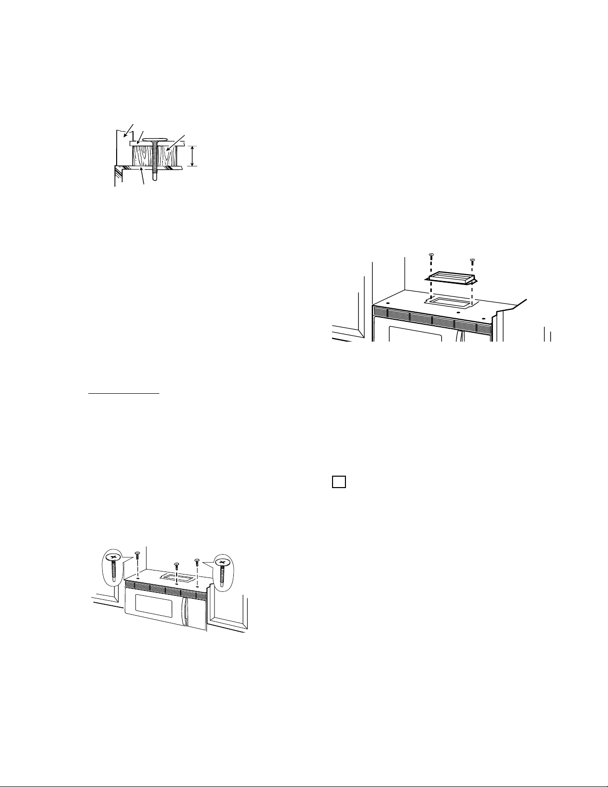
3. Attach the oven to the top cabinet.
NOTE:
1. You'll need to use a filler block if the cabinet
front hangs below the cabinet bottom shelf.
Cabinet Front
Cabinet Bottom Shelf
Oven T op
Filler Block
Minimum 3/16″
2. If your cabinet front hangs more than 23?4″
below the cabinet bottom, you may need to
use longer screws than the ones provided
with this product. The screws provided with
this product (hardware item 3) are selfaligning, large-head machine screws
1
3
?4″ long, with SAE 28 threads per inch. It is
1
?4″ dia.,
important that you use replacement screws
just long enough to attach the product to
the cabinet. The length can be determined by
measuring the height of the overhang from
the top of the cabinet floor to the bottom of
the overhang and adding one inch to that
length. This will be the length of the
1
?4″ SAE
28 threads per inch screws you need.
This is necessary to allow for clearances
of inter
nal parts of your oven.
Insert 2 self-aligning screws (hardware item 3)
through the outer top cabinet holes. Tighten the
center screw completely and then the outer two
screws to the top of the oven. (While tightening
screws, lift the front side of the oven and push
toward the wall.)
4. Install the grease filters and remove the tape
from the cooktop lamp covers on the bottom
of the oven.
5. Secure the power cord to the cabinet wall, as
desired to keep excess length out of the way.
Use the power cord strap (hardware item 7)
and the black metal screw (hardware item 6).
6. For top exhaust on flat bottomed
cabinets, open the top cabinet and attach the
exhaust adaptor to the oven through the
cabinet bottom.
• Remove and discard the 2 screws for the
blower plate.
• Position the exhaust adaptor (hardware
item 5) over the blower plate, hinge side
toward the back of the oven.
• Attach the exhaust adaptor to the blower
plate using the 2 bronze metal screws
provided (hardware item 6).
Make sure the damper moves freely in the
exhaust adaptor.
Pull the house duct down to connect to the
exhaust adaptor. Tape duct using duct tape.
3
You will also need to use washers
?4″ dia. to fit
the screws you purchase. This will prevent the
screw heads from pulling through the bottom of
the cabinet when tightening during installation.
9
INSTALLATION CHECKLIST
1. Make sure the oven has been installed
according to instructions.
2. Remove all packing material from the oven.
3. Replace house fuse or turn breaker back on.
4. Plug power cord into outlet.
5. Read the Owner's Manual.
6. KEEP INSTALLATION INSTRUCTIONS
FOR THE LOCAL INSPECTOR'S USE.
– 13 –
Page 16
he facts about Advantium™.
T
Six o'clock. What's for dinner? How
about a delicious family meal, cooked
in a fraction of the time needed in a
traditional oven?
With GE's revolutionary new speed
cooking oven, you can eat well, and
eat fast. Imagine a home cooked, great
tasting family meal in less time that it
takes to preheat a traditional oven. This
Profile Performance
become the most used appliance in
your kitchen!
Its family size oven can easily cook a
four-pound chicken or lasagna for a
family of four. No preheat is necessary!
It's easy to clean and easy to use.
No complex formulas or controls—
just dial a specific food group and the
cook time is pre-programmed for
cooking perfection.
This oven is so versatile, it will cook
virtually all of your family's meals,
including great tasting foods like these:
• Rolls
• Cookies
• Chicken breasts
• Whole chickens
• Steak
• Roasts
• Pork chops
• Shrimp
And with the push of a button, this
versatile oven converts to microwave
mode for added convenience.
Choose from black, white, bisque
and stainless steel.
™
oven is soon to
• Fish
• Appetizers
• Pizza
• Casseroles
• Lasagna
• Potatoes
• Fresh vegetables
• Desserts
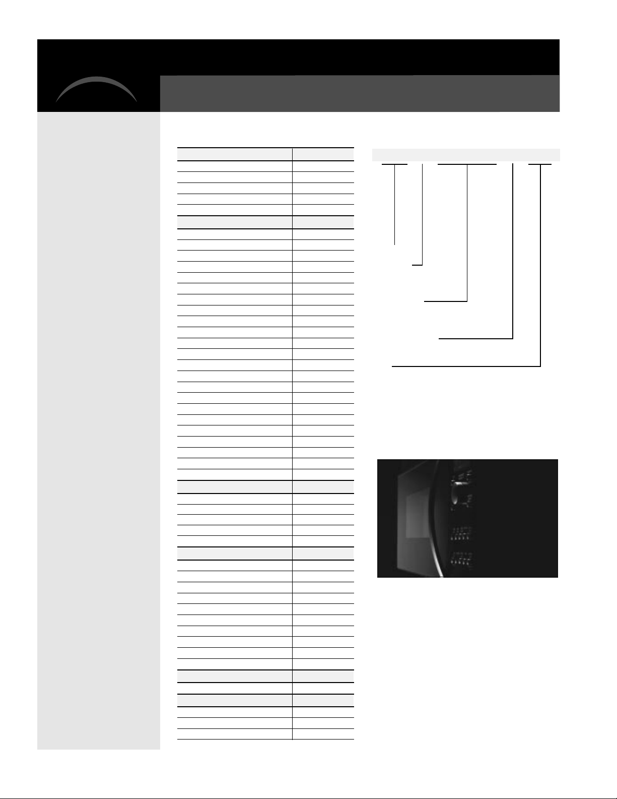
Specifications:
Specifications Nomenclature
Color Options
Model SCA2000BAA Almond
Model SCA2000BBB Black
Model SCA2000BCC Bisque
Model SCA2000BWW White
Model SCA2001BSS Stainless Steel
Features
Stainless Steel Oven Interior ●
Family Size Oven ●
Oven Controls:
Electronic Scrolling Display ●
Over 100 Preprogrammed Menu Items ●
Repeat Last ●
Help Mode ●
Demo Mode ●
Interior Oven Light ●
Beeper Sound Level Control ●
Variable Scroll Speed ●
Reminder ●
Cooking Complete Reminder ●
Child Lock-Out ●
Two-Speed High-Capacity Exhaust Fan ●
Full-View Cooktop Lighting ●
Programmable Night Light ●
Auto Night Light ●
Frameless Glass Oven Door with Window ●
Microwave Oven Features:
Sensor ●
Defrost - Auto/Time ●
Microwave Power Output Watts 950
Accessories
Cookbook ●
Black Metal Grill Tray ●
Black Metal Tray ●
White Ceramic Tray ●
Recirculating Filter Kit (Optional) JX81A
Weights & Dimensions
Approx. Shipping Weight 81
Overall Oven Interior Dimensions
Height 8-13/32"
Width 18-29/32"
Depth 13-19/32"
Overall Dimensions
Exterior Height (front) 15-19/32"
Exterior Height (rear) 16-3/32"
Exterior Width 29-7/8"
Exterior Depth (not including handle) 14-13/16"
Power/Ratings
Amps @ 240V/208V 30
Warranty
Full One-year In-Home Warranty* ●
Full Ten-year Lamp Warranty* ●
Limited Ten-year Magnetron Warranty* ●
*See written warranty for details.
– 14 –
SCA2000BBB
Speedcook Oven
Configuration
A = Above the cooktop
B = Built-in style
Feature Package
2000 = Color model
2001 = Stainless steel
Model Year Designator
Color
WW = White on white
BB = Black on black
CC = Bisque
AA = Almond on almond
SS = Stainless steel
Page 17

W arranty:
For the period of:
GE will replace:
Full one-year Entire oven
From the date of the
original purchase
Any part
workmanship. During this
provide,
the defective part.
of the oven which fails due to a defect in materials or
free of charge,
full one-year warranty,
all labor and in-home service to replace
GE will also
Full ten-year Halogen lamps
From the second through
the tenth year from the
date of original purchase
The halogen speedcook lamps,
to a defect in materials or workmanship. During this
warranty,
in-home service to replace the defective part.
GE will also provide,
if the halogen lamps fail due
full ten-year
free of charge,
all labor and
Limited ten-year Magnetron tube
From the second through the
tenth year from the date of
original purchase
The magnetron tube,
in materials or workmanship. During this additional limited
nine-year warranty
in-home service costs.
if the magnetron tube fails due to a defect
, you will be responsible for any labor or
What GE will not cover:
• Service trips to your home to teach you how to use the product.
• Improper installation.
• Failure of the product if it is abused, misused, or used for other than the
intended purpose, or used commercially.
• Replacement of house fuses or resetting of circuit breakers.
• Damage to the product caused by accident, fire, floods, or acts of God.
• Incidental or consequential damage to personal property caused by possible
defects with this appliance.
• Full one-year
warranty on
parts and labor
• Full ten-year
warranty on
halogen lamps
• Limited ten-year
warranty on
magnetron tube
This warranty is extended to the original purchaser and any succeeding owner for products
purchased for home use within the USA. In Alaska, the warranty excludes the cost of shipping
or service calls to your home.
Some states do not allow the exclusion or limitation to incidental or consequential damages.
This warranty gives you specific legal rights, and you may also have other rights which vary
from state to state. To know what your legal rights are, consult your local or state consumer
affairs office or your state's Attorney General.
Warrantor: General Electric Company. Louisville, KY 40225
– 15 –
Page 18
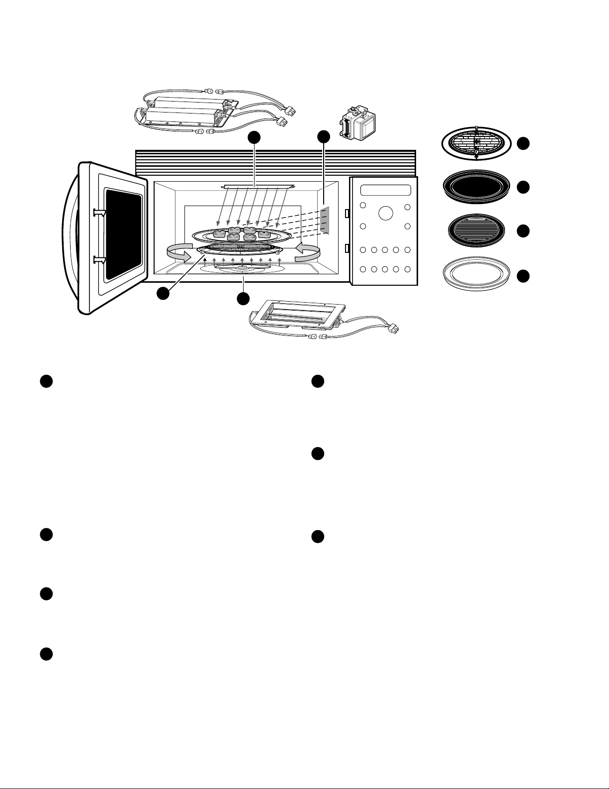
ADVANTIUM™ OVERVIEW
4
1
Upper Halogen Lamp Assembly
Two 1500 watt halogen lamps provide heat
from the top of the oven cavity. These
elements are individually controlled by the
smart board. These elements are used only
for speedcooking operation; however,
during microwave cooking the upper rear
element can be energized for 5 seconds, by
pushing the "Microwave Oven Light" pad on
the control panel. This will illuminate the
oven cavity long enough for the customer to
see the contents inside the oven.
1
2
3
5
Black Metal Tray / Baking Sheet
Used during speedcooking only. Put food
directly on the black metal tray and place on
the oven rack (turntable) when using the
speedcook features.
6
Black Metal Grill Tray / Baking Sheet
Used during speedcooking only. Put food
directly on the black metal grill tray and
place on the oven rack (turntable) when
speedcooking food you would normally
cook on a grill.
4
5
6
7
Lower Halogen Lamp Assembly
2
One 1500 watt halogen lamp provides heat
from the bottom of the oven cavity. Used
only during speedcooking.
3
Wave Guide
Microwave energy from the magnetron tube,
is directed through the wave guide into the
oven cavity.
Oven turntable
4
The turntable rotates the food during speedcook operation and during microwave
operation. The rotation of food serves to
evenly distribute the microwave energy and
halogen heat.
– 16 –
7
White Ceramic Tray
Used during microwave oven cooking only.
Place on the oven rack (turntable) when
using the microwave features. Place food or
microwave-safe cookware directly on the
tray.
Page 19
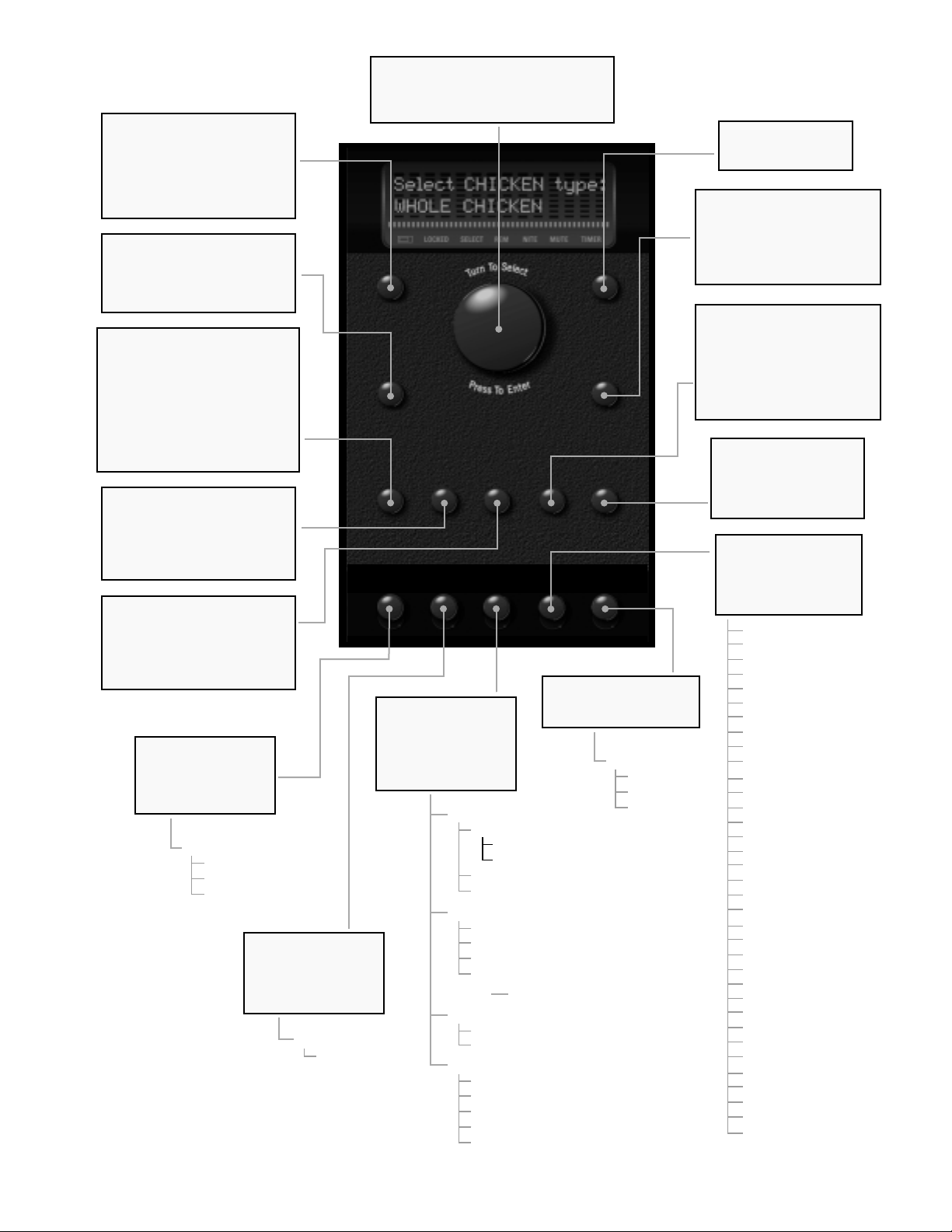
SPEEDCOOK / REPEAT LAST
Allows user to select a pre-set
speedcook program from a
group of menu selections.
Press and hold for 3 seconds to
repeat last cooking selection
(last program is stored for 2 hrs)
MANUAL COOK / RECIPE
Used for cooking foods that are
not in the pre-set selection
menus. Also used to create &
store custom cooking recipes.
POWER LEVEL
Used with the selector dial to
change halogen lamp power
levels (Upper & Lower) and
Microwave power levels during
speedcook operation. Also used
to change microwave power level
during microwave only operation.
Controls % "on" time of each
cooking component.
DELAY START
Program the oven to start at a
preset time. You cannot use this
function with:
POPCORN, REHEAT
programs.
TIMER
General purpose timer. Can be
used while cooking in oven. To
cancel an entry after starting
the timer, press and hold the
timer button for 3 seconds.
VENT FAN
Activates 300 CFM
fan to remove steam
and other vapors from
surface cooking
BEVERAGE,
or
SOUP
Vent Fan
High
Low
Off
REMINDER
Use as an alarm
clock, even during
cooking. Can be set
up to 24 hours ahead.
Set Reminder
Time
SELECTOR DIAL
The heart of the user controls. Just turn
& tap to select cooking programs, adjust
timer and power levels.
SPEEDCOOK
REPEAT LAST
MANUAL COOK
RECIPE
POWER
LEVEL
VENT
HIGH-LOW-OFF
DELAY
START TIMER
FAN REMINDER OPTIONS
OPTIONS
Choose & set: clock,
auto night light,
beeper volume, clock
display on/off, and
display scroll speed.
ON/OFF
MICRO
WAVE
OVEN LIGHT
HELP
SURFACE LIGHT
Lights the cooktop below
with two surface settings
Auto Night Light
Set Auto Night Light
On time
Off Time
Review on-off times
Clear settings
Beeper V olume
Mute
Low
Normal
Loud
Clock (time of day)
Clock Display
On
Off
Scroll Speed
Slow
Med-slow
Normal
Med-fast
Fast
START
PAUSE
CLEAR
OFF
MICRO
EXPRESS
SURFACE
LIGHT
BRIGHT-NIGHT-OFF
Surface Light
Bright
Night
Off
START / PAUSE
Starts or pauses any
cooking function.
CLEAR / OFF
Cancels all oven programs
except: clock, timer, reminder,
and delay start.
Child lockout - hold for 3 secs.
to lock or to unlock controls
MICROWAVE / OVEN LIGHT
Press to active the selector
dial to microwave mode.
Press during microwave cooking to light the oven cavity (top
rear halogen lamp on for
approximately 3 seconds)
MICRO EXPRESS
Gives you 30 seconds
of microwave cooking
each time you press it.
Oven starts immediately
HELP
Find out more about
the oven features. The
scrolling display guides
you through the steps
Auto night light
Beeper volume
Beverage
Child lockout
Clear/off
Clock
Clock display on/off
Defrost (auto)
Defrost (time)
Delayed start
Help
Manual speedcook
Microwave cooking
Microwave express
Options
Oven light
Popcorn
Power level
Recipe/custom
Reheat - 1 serving
Reminder
Repeat last
Resume
Review
Scroll speed
Soup
Speedcook
Start/pause
Surface light
Time cook
Timer on/off
Vegetable (fresh)
Vegetable (canned)
Vegetable (frozen
Vent Fan
– 17 –
Page 20

Cooking Guide
TM
This Cooking Guide is a quick reference for
cooking the foods you always enjoy - only faster.
With these tips, you can easily take advantage of
Advantium's flexibility in cooking to your taste,
so food comes out just the way you want it.
Quick Start
STEP 1 Press the SPEEDCOOK button
STEP 2 Turn the dial to select the type of food you
want. Press the dial to enter it.
STEP 3 Turn the dial to select the specific food. Press
the dial to enter it.
STEP 4 Turn the dial to select the amount, size and/or
doneness (if required, the oven will prompt
you). Press the dial after each selection.
STEP 5 Once the display shows "ADJUST TIME OR
START," either press the dial or start button
NOTE: For first time oven use, clock must be set prior to oven
operation
to start cooking.
YOUR FOOD IS READY
YOUR FOOD IS READY
Speedcook
Turn To Select
Manual Cook
Recipe
Power Level
Vent Fan Reminder Options Help Surface Light
Press To Enter
Selector Dial
TimerDelay Start
Microwave
Oven Light
Start
Pause
Clear
Off
Micro Express
Table of Contents
Quick Start . . . . . . . . . . . . . . . . . . . . . . . 18
Cooking Controls . . . . . . . . . . . . . . . . . . . 18
Speedcook Preset Menu Guide . . . . . . . . 19
Food Placement. . . . . . . . . . . . . . . . . . . . 20
General Cooking Tips. . . . . . . . . . . . . . . . 20
Adjusting Power Levels . . . . . . . . . . . . . . 20
Recipe Adapting . . . . . . . . . . . . . . . . . . . 21
Cooking Controls
SPEEDCOOK/REPEAT
LAST
Press this button to access the preset
speedcook program. Press and hold for
three seconds to repeat the last cooking
selection.
MANUAL COOK/RECIPE
Press this button to set your own speedcook program.
SELECTOR DIAL - TURN
TO SELECT, PRESS TO
ENTER
First turn, then press the dial to make
food selections. Also use this to
increase (turn clockwise) or decrease
(turn counterclockwise) the cooking time.
START/PAUSE
Press this button to start or pause any
cooking selection.
CLEAR/OFF
Press this button to cancel ALL oven programs except the clock, timer and
reminder.
POWER LEVEL
Press this button and use with the selector dial to change the speedcook upper
lamps, lower lamp and microwave power
level before and during cooking.
DELAY START
Press this button to set the oven to start
automatically at a time you set.
TIMER
Press this button to set the minute timer.
MICRO EXPRESS
Press repeatedly for 30 second increments of microwave cooking time. Oven
starts immediately.
VENT FAN
Press this button to remove steam and
other vapors from surface cooking.
REMINDER
Can be used like an alarm clock and can
be used at any time, even when the oven
is operating. It can be set to beep at a
certain time, up to 24 hours later.
OPTIONS
Press this button to set the Clock and
access the Auto Night Light, Beeper
Volume, Clock Display ON/OFF, Display
Scroll Speed features.
HELP
Press this button to find out more about
your oven's features.
SURFACE LIGHT
Press this button to turn the cooktop light
on and off.
MICROWAVE/OVEN LIGHT
Press this button to operate the
microwave. Press while microwave cooking to light the oven cavity. The light will
come on for several seconds.
– 18 –
Page 21

Speedcook Preset Menu Guide
Advantium is already preset to cook more than 100 of America's favorite dishes. When speed cooking preset foods,
refer to the following guide. This listing includes all of the preset food types, the brands that we tested and helpful
cooking tips.
APPETIZERS/SNACKS
Preset Foods
Bagel Bites
Cheese Sticks, froz.
Jalapeno Poppers
Mini Egg Rolls, froz.
Mini Nachos, froz.
Onion Rings, froz.
Other Bite Size Pizza
Rolls, froz.
Cooking Tip
Arrange pieces in center of
black metal tray.
Filling may leak out as in
conventional cooking.
Arrange in single layer;
turn over after 1/2 of cooking time. For crisper texture, increase time in 15
second increments.
Filling may leak out as in
conventional cooking.
BREADS
Biscuits, refrig.
Large - 8
5
Small - 10 to 12
5 to 6
Biscuits, Blueberry
Breadsticks, refrig.
Cheese Loaf, froz.
Cornbread Sticks, froz.
Crescent Rolls
French Bread, refrig.
Garlic/Cheese Bread
Loaf, refrig.
Texas Toast
Place 1 biscuit in center
and 7 surrounding it on
black metal tray.
Place in circle around
black metal tray.
Place 2 biscuits in center
and 8 around them on
black metal tray.
Same as large biscuits.
Same as large biscuits.
Remove all wrappings.
Remove all wrappings.
Arrange in spoke pattern
on black metal tray.
Arrange in spoke pattern.
Cut loaf in half, lengthwise.
Follow pkg. directions
for greasing.
Remove all wrappings.
Cut whole loaves in half.
Use glass dish sprayed
®
with PAM.
BREAKFAST
Belgian Waffles
Breakfast Burritos
Breakfast Pizza
Cinnamon Rolls, refrig.
French Toast, froz.
1 - 2 pieces
3 - 4 pieces
Pancakes, froz.
Sausage Links
Sausage Patties
Strudels, froz.
Waffles, froz.
Waffle Sticks, froz.
When cooking 4 pizzas, one
may extend over edge of
black metal tray.
Place in circle on black
metal tray.
Arrange in single layer or
short stacks on black
metal tray.
Turn over during last min.
1/2- inch thick.
Brands Tested
®
Totino's
®
Ore Ida
Ore Ida
®
La Choy
Totino's
Ore Ida
®
Kroger
Totino's
Pillsbury Big
®
Country
, Kroger
Jumbo Buttermilk,
Pillsbury Grands
Hungry Jack®Flaky
Layer
Kroger Home-Style,
®
Pillsbury 1869
Pillsbury Buttermilk,
Kroger Buttermilk
Pillsbury Grands
Pillsbury Garlic,
Kroger Soft
Cole's
Pepperidge Farm
Pillsbury
Pillsbury, Pillsbury
Reduced Fat,
Kroger
Pillsbury
Kroger, Meijer
Cole's
Pillsbury White
Home-Style,
Pillsbury Wheat
Home-Style
Texas Toast
Belgian Chef
Old El Paso
Red Baron
Western Scramble
Pillsbury Large,
Pillsbury Large
Reduced Fat,
Pillsbury Small,
Pillsbury Small
Reduced Fat
Murry's
Pillsbury
Buttermilk, Aunt
Jemima
Jack
Pillsbury
Pillsbury Buttermilk,
Aunt Jemima,
Hungry Jack,
Eggo
Churro Brand
®
,
®
®
, Kellogg
,
®
®
®
, Hungry
®
,
®
CHICKEN
Preset Foods
Bone-In Pieces
Boneless Breasts
Fingers, froz.
Fried Chicken, froz.
Nuggets, froz.
Patties
Tenders, froz.
Whole Chicken
Wings, froz.
DESSERTS
®
Churros, froz.
Cookie Dough, froz.
Cookie Dough, refrig.
Teaspoon size
Tablespoon size
Pie Crust, refrig.
Turnovers, froz.
®
Turnovers, refrig.
FISH & SEAFOOD
Breaded Fish, froz.
Fish Sticks, froz.
Salmon Steaks
Shellfish
Swordfish Steaks
Tuna Steaks
Whitefish Fillets
MEATS
Filet Mignon
Hamburger
Lamb chops
Pork Chops
Steaks, Ribeye
Steaks, Sirloin
Steaks, Strip
Steaks, T-bone
Cooking Tip
Small pieces cook faster;
remove from oven as
cooking is completed.
Arrange in single layer.
Small pieces cook faster;
remove from oven as
cooking is completed.
Arrange in single layer.
For chickens larger than
5 lbs., add 5 min./lb.
Barbecue sauce burns
easily; do not overcook.
Do not thaw before baking.
Place 4 in center and 8
around edge of black
metal tray. Follow pkg.
directions for cooling.
Place 1 in center and 4
around edge or 5 around
edge of black metal tray.
Follow pkg. directions for
cooling.
Prick bottom and sides of
unbaked crust with fork.
Lightly oil pan with olive
oil. Tips of salmon should
be interlocked to prevent
overcooking. Maximum
thickness 1-1/2 in.
Place shrimp in single
layer on black metal tray
without overlapping. Cook
in or out of shell.
Max. thickness 1-1/2 in.
Brush tray with olive or
vegetable oil.
Bacon wrapped around
filet may cause smoking.
Leaner ground beef will
reduce spattering during
cooking.
Add sauces during last
2-3 min.
Slash fat to prevent
curling.
Brands Tested
Purdue®, Holly
Farms®, Kroger
®
Tyson
Tyson
Tyson, Banquet
Kroger
Coming Home
Purdue, Holly
Farms, Kroger
Tyson Barbecue
Otis Spunkmeyer
Pillsbury, Kroger,
Kroger Reduced
Fat
Pepperidge Farm
Pillsbury
®
Mrs. Paul's
®
Gorton's
Mrs. Paul's ,
Gorton's
N/A
N/A
N/A
N/A
N/A
N/A
N/A
N/A
N/A
N/A
N/A
N/A
N/A
PIZZA
Preset Foods
Deli/Fresh
Pizza Shell, filled
Rising Crust, froz.
®
,
Thin Crust, froz.
®
POTATOES
Baked Potatoes
Frozen French Fries
®
Crinkle Fries
Coated Fries
Regular Fries
Steak Fries
Waffle Fries
Frozen Tater Tots
SANDWICHES
Burritos, froz.
,
Corn Dogs
Crescent Roll/Hot Dogs
Grilled Sandwiches
Pocket Sandwiches
Cooking Tip
Oven will signal to check
doneness at minimum
time. Increase time
as needed in 15 sec.
increments.
Pierce skin with fork in
several places. Select
appropriate size for best
cooking results.
For crisper texture,
increase time in 15 second
increments.Follow pkg.
directions for serving size.
Filling may leak out as in
conventional cooking.
Arrange on black metal
tray in spoke pattern.
Butter both outer sides of
bread before cooking.
Brands Tested
Mama Rosa
®
Boboli
TombstoneTM,
Kroger, Red
®
Baron
,
TM
Freschetta
®
Digiorno
Totino's, Tony's
Ore Ida, Kroger
Brands Tested
Marquez®, Old
El Paso
®
State Fair
,
®
Kahn's
, Meijer
N/A
N/A
Hot Pockets
Lean Cuisine
®
,
TM
®
,
®
– 19 –
Page 22

Food Placement
To ensure consistent and even browning when cooking foods directly on the black metal tray, arrange food as shown below. Foods can touch but
should not overlap.
Circular Pattern
(ex: biscuits, cookies)
(ex: biscuits, cookies, meats)
General Cooking Tips
•
Always check food for doneness at minimum
time. Use the same methods you would for conventional cooking. For example, check doneness of
meat and poultry with a meat
thermometer. Check cakes by inserting a
toothpick near center.
• Add toppings, such as cheese or crumbs, and
sauces, such as barbecue, during the last 2 to 3
minutes of cooking time.
• Remember that the quantity of food affects
cooking time. Larger quantities or sizes will
increase cooking time; smaller amounts will cook
in less time.
• To determine the weight of each piece of
chicken divide the package weight by number
of pieces.
• Select appropriate thickness for steaks.
• Adjust the cooking time by turning the
selector dial. Turn clockwise to increase time or
counterclockwise to decrease time.
• Fresh meat, chicken, fish or seafood that has
been frozen should be thawed before cooking
(the microwave defrost feature can be used).
For other frozen prepackaged foods, follow
package directions.
• To program your favorite recipe, press the
Speedcook button. Turn the dial until Recipe
appears. Press to enter. Follow the directions on
the control. (For more detailed information, refer
to your Owner's Manual.)
Circular Pattern
Spoke Pattern
(ex: crescent rolls, breadsticks)
USING THE OVEN
• Place the oven rack (turntable) on the floor
of the oven for all cooking procedures. When
cooking with the speedcook feature, place
casseroles and baking dishes directly on the
oven rack (turntable).
• The black metal tray is placed on the oven
rack (turntable) and used for many speedcook
functions. Use it for baking cookies, biscuits
and rolls, grilling sandwiches, cooking pizzas
and bite-size hors d'oeuvres. Fish fillets and
chicken pieces can also be cooked on the black
metal tray.
• The black metal grill tray is used for steaks,
chops, burgers, chicken and fish that are usually
cooked on a grill. Place the grill tray directly on
the oven rack (turntable).
• Always place the white ceramic tray on
the oven rack (turntable) when cooking with
microwaves only. Place the cookware on the
white ceramic tray.
• Brush the black metal tray or black metal
grill tray lightly with olive or vegetable oil before
cooking foods that might stick (example: boneless,
skinless chicken breasts and fish fillets which contain little fat)
.
Single Layer
(ex: appetizers)
COOKWARE SELECTION
• Any oven-safe dish can be used in your
oven. Recipes in the Advantium Cookbook were
tested in Pyrex
cookware and Corningware
Cooktimes and results may vary when using
other types of oven-safe dishes.
• Do not use metal utensils in the oven with
the exception of 6-cup muffin pans. (Microwave
power level must be set at zero). Place the muffin pan directly on the oven rack (turntable).
• Paper products and wraps should not be
used in the Advantium oven when cooking with
the speedcook feature.
• When using the speedcook feature, dishes,
trays and the oven itself will be hot. Always use
oven mitts or hot pads when removing dishes
from the oven.
®
and Anchor Hocking®glass
®
ceramic casseroles.
CLEANING THE OVEN
• Light soil on oven walls, floor and inside win-
dow can be removed with a paper towel or damp
cloth. Remove greasy soil with a sudsy cloth,
then rinse with a damp cloth.
• Let trays cool before cleaning. Wash in
warm, sudsy water or in the dishwasher.
• Clean the oven rack (turntable) in
warm, sudsy water, dry thoroughly and return
to the oven.
• Always keep the upper and lower lamp
covers clean for best cooking results. When
cool, wipe off the covers with a damp cloth.
For baked on soil use your cleaning scraper.
Adjusting Power Levels
Power from high intensity halogen lights and microwave cooks food from the top, bottom and interior simultaneously to seal in
moisture and flavor. Power level settings can be adjusted when cooking both preset menu foods and your own recipes. Just press
the power level button prior to pushing start. Turn the dial to select and press the dial to enter desired levels.
Upper
Lamp
U L M
Setting
Each setting gives you halogen lamp power and
microwave energy for a certain percentage of the time.
Example: U=07 provides upper halogen lamp power
70% of the cooking time. L=07 provides lower halogen
lamp power 70% of the cooking time. M=05 provides
microwave energy for 50% of the cooking time.
Lower
Lamp
Setting
Microwave
Setting
Follow these general guidelines when selecting the best U= L= M= settings for your favorite recipes:
U = Select a higher setting for thin foods requiring a golden brown top (example: fish fillets,
toast, boneless chicken breasts). Select a lower setting for thicker foods and foods with high
sugar or fat content (example: cakes, roasts).
L = Select a higher setting for thick or dense foods that may not cook quickly in the center
(example: casseroles). Select a lower setting for thin foods (example: cookies) and foods containing high fat or sugar content (example: pastry, cakes).
M = Select a higher setting to shorten cooking time for dense or heavy foods (example:
casseroles, whole chicken). Select a lower setting for delicate foods (example: cakes, breads,
souffles) or foods requiring longer cook times for tender results (example: stew, pot roast).
– 20 –
Page 23

Recipe Adapting
When adapting your favorite recipes for the Advantium oven, use the following charts as a guide. You may also find it helpful to
refer to a similar recipe in the Advantium Cookbook to determine cook time and U/L/M settings.
Food Conventional Oven Advantium Power Advantium Cookware Cooking Tip
Beef
Roast 325˚ U=03 L=05 M=04
Rare 18 min./lb. 13 min./lb.
Medium 20 min./lb. 14 min./lb.
Well Done 22 min./lb. 15 min./lb.
Meat Loaf (1-1/2 lbs.) 350˚/1-1/4 hrs. U=03 L=05 M=03 35 min. Glass loaf dish For 1 lb. loaves subtract 10 minutes;
Pork
Boneless Pork Loin 325˚/30 min./lb. U=05 L=05 M=04 12 min./lb.
(2 to 2-1/2 lbs..) doneness with meat thermometer.
Tenderloin 375˚/30 min./lb. U=07 L=06 M=04 18 min./lb. Turn meat over during last 3 to 5 minutes.
Pork Chops (3 to 4)
3/4 inch thick 350˚/40 min. U=10 L=10 M=03 9 min. Black metal tray Turn chops over during last 2 minutes.
1 inch thick 350˚/50 min. U=10 L=10 M=03 10 min. Black metal tray Turn chops over during last 3 minutes.
Lamb
Roast 325˚/30 min./lb. U=04 L=05 M=05 12 min./lb. 11” x 7” glass dish and glass trivet Turn meat over after half time
(3 to 3-1/2 lbs.)
ROASTING
Poultry
Whole Chicken 375˚ U=05 L=05 M=10
2 to 3 lbs. 28 min./lb. 8 min./lb. 3- or 5-qt. glass casserole & cover
4 to 5 lbs. 24 min./lb. 6 min./lb.
Over 5 lbs. 25 min./lb. Add 5 min./lb.
Piece s
(in sauce) 375˚/55 min. U=07 L=06 M=04 25 min. 1-1/2 or 2-qt. glass casserole & cover
(crumb-coated) 375˚/45 min. U=10 L=10 M=00 10 min. Black metal tray Turn over after half time.
Beef
Steaks (2-boneless) Broil U=10 L=10 M=05
1/2 inch- medium 8 - 10 min. 5 min. Black metal tray Turn over during last 2 to 3 minutes.
well 10 - 12 min. 6 min.
1 inch- medium 13 - 17 min. 8 min.
well 18 - 22 min. 9 min.
1-1/2inch- medium 19 - 22 min. 11 min.
well 23 - 28 min. 13 min.
Steak (2-with bone)
1/2 inch- medium 8 - 10 min. U=10 L=10 M=03 7 min.
well 10 - 12 min. 8 min.
1 inch- medium 13 - 17 min. U=10 L=10 M=05 11 min.
well 18 - 22 min. 12 min.
1-1/2inch- medium 19 - 22 min. 12 min.
well 23 - 28 min. 13 min.
Fish
Steaks Broil Turn fish over after half time. Reduce time for
(1 inch) 12 - 18 min. U=10 L=10 M=05 8 min. thinner steaks; add time for thicker steaks.
BROILINGBAKING
Fillets 8 - 9 min. U=10 L=10 M=00 7 min. Brush black metal tray lightly with oil to
Lamb
Chops (6) Broil U=10 L=10 M=00
1 inch medium 8 - 10 min. 8 min. Turn over during last 2 to 3 minutes.
1-1/2 inch- medium 11 - 13 min. 10 min. Turn over during last 2 to 3 minutes.
Temp/Time Level Settings Cooking Time Suggestion
8”square or 11”x 7”glass dish and glass trivet
8”square or 11”x 7”glass dish and glass trivet
Turn meat over after half time.
for 2 lb. loaves add 8 minutes.
Turn meat over after half time. Check
prevent sticking.
Breads
Biscuits (scratch/mix) 450˚/12 min. U=10 L=03 M=02
Coffee Cake 350˚/35 min. U=05 L=05 M=03
Corn Bread 425˚/25 min. U=06 L=06 M=03
Muffins 400˚/20 min. U=07 L=03 M=00
Desserts
Cakes (heavy batter) 350˚/45 min. U=04 L=06 M=04
Cakes (light batter) 350˚/30 min. U=04 L=06 M=02
Cookies (drop or shaped) 375˚/10 min. U=09 L=01 M=01
Cookies (bar) 350˚/30 min. U=06 L=09 M=03
Pies (one crust) 400˚/45 min. U=06 L=04 M=02
Casseroles
Main Dish 350˚/40 min. U=07 L=04 M=04
Vegetable
Cooked Ingredients 350˚/30 min. U=08 L=05 M=05
Uncooked Ingredients 350˚/50 - 60 min. U=07 L=04 M=04
Eggs and Cheese
Macaroni and Cheese 350˚/30 min. U=07 L=04 M=03
Quiche 350˚/40 min. U=06 L=05 M=03
Souffle 350˚/50 min. U=04 L=04 M=04
6 min.
9 min. 8” square glass dish
7 min. 8” square glass dish
11 min 6-cup metal muffin pan
13 min. 8” square or 11” x 7” glass dish
13 min. 8” square or 11” x 7” glass dish
4 min. Black metal tray
6 min. 8” square glass dish
23 min. 9” glass pie plate
15 min. 1-1/2 to 2-qt. glass dish
15 min.
28 min.
14 min.
18 min. 9” glass pie plate
18 min. 2- to 2-1/2 qt. glass soufflé dish
Black metal tray
– 21 –
Use M=00 when cooking in metal muffin pan.
Use higher M= setting for cakes with heavy batter.
Cool black metal trays to room temperature between
runs. Each successive run may cook slightly faster.
Cool before cutting.
Do not shield fluted edge during cooking.
Add cheese or crumb toppings during
last 2 to 3 minutes.
Cover casserole during cooking.
Let stand 10 minutes before cutting.
Page 24

etting to know Advantium
G
How to Speedcook
To select a speedcook program:
Press Speedcook.
1.
Turn the selector dial until the desired speedcook
2.
food category appears in the display.
Press the dial to select it. The display will now
3.
prompt you through the food selections.
Press Start/Pause or the selector dial, to start
4.
cooking
If the door is opened during cooking, the oven stops and
PAUSE appears in the display. Close the door and press
START/Pause to resume cooking. At any time during the
cooking you can turn the selector dial to change the
cooking time. You can also change power levels.
Press Speedcook button to begin:
Select TYPE:
PIZZA
OVEN LOCKED SELECT REM NITE MUTE TIMER OVEN LOCKED SELECT REM NITE MUTE TIMER OVEN LOCKED SELECT REM NITE MUTE TIMER
Select TYPE of food:
1. Select PIZZA type:
Turn to PIZZA and then press
the selector dial to enter
selection.
Use ROUND METAL TRAY
10:00 U=08 L=07 M=02
OVEN LOCKED SELECT REM NITE MUTE TIMER OVEN LOCKED SELECT REM NITE MUTE TIMER OVEN LOCKED SELECT REM NITE MUTE TIMER
After entering the SIZE, you will
4. ADJUST TIME or START
see a message instructing you
to: Use ROUND METAL TRAY
Be sure the use the metal tray
that came with the Advantium.
OPTIMIZING COOK TIME
9:55
Select PIZZA type:
REG. CRUST, FROZEN
2. Select SIZE:
Turn to REG, CRUST, FROZEN
and then press the selector
dial to enter selection.
ADJUST TIME or START
10:00 U=08 L=07 M=02
5. Once the oven starts cooking
appears. Press Start or selector dial to begin cooking.
CHECK for DONENESS
4:00
Select SIZE:
Regular (12")
3.
Turn to Regular (12") and then
press the selector dial to enter
selection.
REG, CRUST, FROZEN
09:59
6.
you will see your selection in
the display with remaining
cooking time counting down.
YOUR FOOD IS READY
OVEN LOCKED SELECT REM NITE MUTE TIMER OVEN LOCKED SELECT REM NITE MUTE TIMER
After approximately 3-5 secs,
7. Minutes before cooking ends
the cook time may be adjusted
up or down, to compensate for
variations in line voltage.
8.
CHECK for DONENESS
appears. Power shuts off until
restarted (START).
– 22 –
OVEN LOCKED SELECT REM NITE MUTE TIMER
Minutes later enjoy pizza with
9.
a crispy brown crust, and golden melted cheeze. It doesn't
get much easier than this.
Page 25

OPERATING CHARACTERISTICS
Power Levels
Voltage Compensation
Upper Halogen Lamp Balance
Thermal Compensation
Thermal Protection
Thermal Safety
Damper Door Assembly
Damper Door Sensing Switch
Oven Cavity Lamp
Thermal Fuse
Air Flow
24
25
25
25
27
28
28
28
29
29
30
Vent Motor
Halogen Blowers - Upper/Lower
Magnetron Blower
30
30
32
24-25
26-28
28
– 23 –
Page 26

POWER LEVELS
Advantium uses power from high intensity halogen lamps, as well as microwa ve energy , to cook
foods evenly and quickly (average of one-four th
the time of a conventional oven) to seal in moisture and flavor.
Example:Example:
Example: upper element set at 80% (U=08), lower
Example:Example:
element set at 50% (L=05) and microwav e set at
30% (M=03)
Select UPPER POWER:
5:00 U=08 L=05 M=03
Power levels are selected with the selector dial
and can be adjusted before cooking or during
cooking. When using preset menu foods, the
power levels are already selected for you. However, power levels can be adjusted when cooking both preset menu food and when manual
cooking.
Power levels are adjusted independently for the
upper halogen lamps (pair), lower halogen lamp
(single) and microwave energy. When selecting
a upper halogen lamp power lev el, the power level
can only be selected for the pair. You can not
select power levels for the upper rear and upper
front independently.
Power levels of 0 to 10 can be selected for the
upper halogen lamps (pair), lower halogen lamp
and microwav e energy. The pow er lev els control
the percentage of “on” time for the upper halo-
gen lamp pair, the lower halogen lamp and microwave high voltage circuit.
The programming on the smart board which controls the upper and lower halogen lamps, as well
as the high voltage/magnetron circuits, operates
on a duty cycle of 32 seconds. This means the
power level you select for each component controls the percentage of “on” time during each 32
second period of time.
In the example shown in the upper right, the upper halogen lamps would cycle for 80% of each
32 second period, the lower would cycle at 50%
of each 32 second period and the microwave high
voltage circuit would be energized f or 30% of each
32 second period.
80%
L=05
M=03
U=08
30%
50%
80%
M=03
L=05
U=08
30%
50%
80%
% ON
TIME
U=08
L=05
{
M=03
| | | | | | | | | | | | | | | | | | | | | | | | | | | | |
50%
30%
0 32 Secs 64 Secs 96 S
32 Second Duty Cycles
OVEN LOCKED SELECT REM NITE MUTE TIMER
Upper Halogen Lamp Pair (U=)
The upper halogen lamps provide radiant heat
to the top surface of the food. Select a higher
setting for thin foods requiring a golden brown
top (example: fish fillets, toast, boneless chic ken
breasts). Select a lower setting for thicker foods
and foods with high sugar or fat content (e xample:
cakes, roasts).
UPPER HALOGEN
PAIR (U=)
LOWER HALOGEN
LAMP (L=)
MICROWAVE
(M=)
Lower Halogen Lamp (L=)
The lower halogen lamps provide cooking from
below to heat the cooking surface (cooking tr ays
and cookware). Select a higher setting for thick
or dense foods that may not cook quickly in the
center (example: casseroles). Select a lower
setting for thin foods (e xample: cookies) and f oods
containing high fat or sugar content (example:
pastries, cakes).
Microwave Energy (M=)
Microwave energy is provided by the high voltage/magnetron circuit and directed via the wave
guide directly into the oven cavity. As the food
rotates on the oven turntable, microwa ve energy
is evenly distributed to all portions of the food.
Select a higher setting to shorten cooking time
for dense or heavy foods (example: casseroles,
whole chicken). Select a lower setting for delicate foods (e xample: cakes, breads, souffles) or
foods requiring longer cooking times for tender
results (example: stew, pot roast).
– 24 –
Page 27

VOLTAGE COMPENSATION
V oltage fluctuations in the power lines can cause
inconsistencies in cooking. Advantium automatically measures line voltage at the start of each
speedcooking selection and adjusts the cook-
ing time to achieve consistent quality results.
V oltage compensation occurs after approximately
5 seconds of cooking operation. The displa y will
show “OPTIMIZING COOK TIME”. The time will
flash and then display the new adjusted time,
base on the amount of voltage compensation
required.
Line voltage is monitored by the voltage compensation transformer, which is located on the
smart board. This transf ormer monitors the voltage from L2 to neutral.
SMART BOARD
CN5
Voltage Compensation Circuit
The optimal line voltage where no voltage compensation occurs, is 120 VAC. Above 120VAC
time is subtracted to the recipe. Belo w 120 VAC
time is added. The amount of voltage compensation required is dependent upon the incoming
voltage at the start of the cooking cycle, and the
particular speedcooking selection that is chosen.
The chart below shows the predicted compensation times based on a 5 minute speedcook
selection (such as: Biscuits, Refr ; Large; 8 biscuits).
OPTIMIZING COOK TIME
9:55
OVEN LOCKED SELECT REM NITE MUTE TIMER
Voltage compensation only occurs during
speedcook operation and only occurs once during the cooking cycle (at initial start of speedcook
operation).
UPPER HALOGEN LAMP BALANCE
As stated previously, the upper halogen lamp pair
operate together at the same power lev el. However, in order to provide even (balanced) cooking performance, the upper rear halogen lamp
will always cycle at 85% of the upper front halogen lamp. In other words, if the upper halogen
lamps are set at power lev el 10 (U=10) you would
expect both elements to operate at 100% of each
32 second duty cycle. Instead, the upper rear
halogen will cycle at 85% of power level 10, or
85% of 32 seconds. You will always notice the
upper rear halogen lamp will cycle off just prior
to the upper front.
VOLTAGE
L2 to N
108 60.0
110 47.9
112 36.7
114 26.3
116 16.7
118 7.9
120 0.0
122 -7.1
124 -13.3
126 -18.8
128 -23.3
130 -27.1
132 -30.0
Predicted Compensation Times Based
on a 5:00 Speedcook Selection (such
as: Biscuits, Refr; Large; 8 biscuits)
TIME (secs)
COMPENSATION
THERMAL COMPENSATION
When cooking sever al food items consecutively,
the temperature in the oven’s interior can become
very hot. The Advantium speedcooking program
(smart board) automatically compensates for the
increased temperature by adjusting the cooking
power levels of the upper and/or lower halogen
lamps. This innovative technology gives you
oven-quality food with consistent results.
Located inside of the oven ca vity (upper right rear)
is a thermistor. At the start of each new
speedcooking operation (just prior to voltage
compensation occurring), the cavity thermistor
reads the oven cavity temperature. Depending
– 25 –
Page 28

upon the oven cavity temper ature and the amount
of cooking time selected, the smart board will
adjust the power level of the upper and/or the
lower halogen lamps to compensate for the additional heat that may already exists in the oven
cavity (if previous cooking occurred).
OVEN CAVITY
THERMISTOR
Thermal compensation can affect the upper halogen lamp power level, the lower halogen lamp
power lev el or both the upper and lower halogen
power levels simultaneously. Thermal compensation can lower the upper halogen pair by 1, 2
or 3 power levels. The lower halogen lamp can
also be reduced by 1, 2 or 3 power levels, but
never independently of the top halogen lamp pair .
In other words, thermal compensation on the
lower lamps will never be greater than the compensation occurring on the top lamps. It is possible howe ver to hav e thermal compensation occurring on the upper halogen lamp pair, but not
on the lower.
Neither the upper halogen lamp pair, or the lo wer
halogen lamp can be compensated below power
levels of 2. In other w ords, if a power le vel of 3 is
selected for either the upper halogen pair , or the
lower halogen lamp, then thermal compensation
can only reduce the power level by a maximum
of 1 power level.
levels) depends upon the temperature of the o ven
cavity at the start of the speedcook operation and
the amount of time selected.
When thermal compensation occurs, it is not
possible to see the adjusted power le v els in the
display. If you where to press the power level
pad during a speedcook operation, in which thermal compensation occurred, you would not see
the adjusted power levels in the display. In fact,
what you would see is the original power level
setting. Ho wever, y ou can visually see compensation occurring by carefully observing the cycling of the halogen lamps.
CAUTION: when viewing the halogen lamps, do
not stare directly into the face of the door window. View the oven interior from a distance far
enough not to cause eye strain.
Thermal Compensation Test
To better understand this operation you can perform the following test (only if the oven cavity is
at room temperature). Remove the pan from the
oven so you can see both the upper and lower
halogen lamps. Select Speedcook, Meats, Hamburger, 1/2 inch thick, 1-2 patties. The following
will show in the display:
ADJUST TIME or START
3:00 U=10 L=10 M=10
OVEN LOCKED SELECT REM NITE MUTE TIMER
Notice that the display shows pow er levels of 10
for each cooking component. During this test you
will be operating the oven with no load. For this
reason, it will be necessary to adjust the micro-
wave power level to zero (M=00). To do this,
press the power lev el button on the control panel.
Leave the upper and lower power levels at 10
(U=10 L=10), and adjust the microwave to zero
(M=00).
Thermal compensation only occurs when oven
cavity temperatures are higher than normal from
the previous cooking operation. When thermal
compensation is required, it will occur immediately upon the start of a new speedcook operation (just prior to voltage compensation occurring) and there will be no indication in the display
that thermal compensation has occurred. The
amount of thermal compensation (1, 2 or 3 power
Press START to run
3:00 U=10 L=10 M=00
OVEN LOCKED SELECT REM NITE MUTE TIMER
NOTE: Set Microwave to Zero (M=00)
– 26 –
Page 29

Start the speedcook operation and carefully notice the cycling of the halogen lamps. At power
levels of 10, both the upper halogen pair , and the
lower halogen lamp should be on 100% of the
time. However, remember that the upper rear
halogen lamp always cycles at 85% of the upper
halogen power level setting; so you will be able
to see the upper rear halogen lamp cycle off
briefly (see “
UPPER HALOGEN LAMP BALANCE - Pg
25” for additional information).
With approximately 1 minute remaining the ov en
will stop and you will be instructed to turn over
the food. Briefly open the door and close it, and
then touch the start pad to resume the remainder of the cooking time. At the end of the cooking cycle repeat the steps above, using the same
hamburger selection (remember to once again
set the microwave po wer level to zero (
M=00).
Once again pay attention to the halogen lamp
cycling. Since the oven is now hot, you should
be able to visually see thermal compensation
occurring. You will notice that both the upper and
lower halogen lamp power levels have been decreased by some amount.
THERMAL PROTECTION
If oven cavity temperatures reach some where in
the range of 500 to 600 degrees, or if a speedcooking selection is chosen which exceeds 12
minutes of cooking at halogen lamp power lev els
(upper and lower) greater than 7, all power levels (upper, low er and microwav e) will be reduced
to 7 for the remainder of the speedcooking selection. This system allows for safe exterior operating temperatures.
In the unlikely event that thermal protection is
required, the consumer will not notice any change
in the display readout (no power level change
indication), however, they may notice that the
halogen lamps are cycling differently than the
expected, due to the change in power levels.
SMART BOARD
What is important to note is that while the power
levels have been reduced (thermal compensation) the power lev els which will show in the display (if you touch the power level pad while
speedcooking operation is occurring) will be the
original power levels (U=10, L=10 and M=00).
From a consumer’s point of view , if the consumer
were to cook two hamburger patties, and then
immediately cook two more patties, they could
notice the halogen lamps cycling differently with
the same selection used each time. This is perfectly normal when thermal compensation occurs.
The consumer’s Use & Care manual state the
following:
Page 20 - Lights (Use & Care Guide)
The halogen lights will dim and cycle on and off
during a speedcook cycle, sometimes even at
full power lev els. This is normal. The oven senses
the heat level and adjusts automatically.
Page 41 - T roub leshooting, Lights (Use & Care
Guide)
Light during a speedcook cycle dims and cycles
on and off, e v en at full po w er levels. This is normal. The power le v el has been automatically reduced because the oven is hot. The oven senses
the heat level and adjusts automatically.
OVEN CAVITY
THERMISTOR
As was the case with thermal compensation, the
control is provided by the thermistor and smart
board, with the thermistor sensing the oven cavity temperature and the control board providing
the proper responses to lower all power le vels to
7.
SMART BOARD
CN6 CN4 CN2
DAMPER
DOOR
SENSING
SWITCH
OVEN CAVITY THERMISTOR
AND SMARTBOARD
– 27 –
Page 30

THERMAL SAFETY
In the unlikely ev ent that internal oven cavity temperatures exceed 600+ degrees F., speedcooking
operation will be terminated.
The oven cavity thermistor is constantly sensing
oven cavity temperatures and providing input to
the smartboard. When the smar tboard determines that 600+ degrees F. has been reached, it
will terminate speedcooking operation and return
the oven display to its nor mal off position (with
time-of-day clock sho wing in the displa y). When
the unit cools, it will return to normal operation.
Thermal safety provides an additional means of
thermal protection, in addition to the thermal protection mode mentioned on the previous page.
DAMPER DOOR SHOWN IN OPEN
POSITION ALLOWING AIRFLOW
INTO OVEN CAVITY
DAMPER
DOOR ASSY
Also during microwave cooking the metal damper
door is fully open, allowing the oven cavity lamp
to illuminate the oven interior.
DAMPER DOOR ASSEMBLY
The damper door assembly has a metal semiround door, which rotates by control of a damper
motor, to open and close off air from the damper
chamber to the oven cavity. The thermal fuse,
door sensing switch and ov en cavity lamp mount
to the damper door assembly.
THERMAL
FUSE
DAMPER
MOTOR
DOOR
SENSING
SWITCH
OVEN CAVITY
LAMP
THERMAL
FUSE
MOUNTS TO
OVEN CAVITY
MOUNTS TO
MAG TUBE
OVEN CAVITY
LAMP SOCKET
INSIDE BOTTOM VIEW OF DAMPER DOOR ASSEMBLY
During speedcooking operation (recipe or manual
speedcook), the metal damper door rotates into
the damper chamber, closing off air flow from the
magnetron blower into the ov en cavity , and blocking the oven cavity lamp from illuminating the
oven interior. In doing so, heat from the oven
interior is contained in the oven cavity.
During microwave o ven cooking, the damper door
is fully open allowing air to travel through and
around the magnetron tube, into the oven cavity
(see illustration upper right).
Door Sensing Switch
The damper door sensing switch is mounted to
the damper duct. The switch monitors the metal
door position and provides this information to the
smart board (metal damper door open or metal
damper door closed) which controls the direction and operation of the damper door motor. If
the damper door sensing switch shorts, or opens,
– 28 –
Page 31

the damper motor will continually cycle the
damper door open and closed until one complete
switch cycle is detected.
Damper Door Closed:
The illustration below shows the position of the
metal damper door in the open position. In this
position the oven cavity lamp can illuminate the
oven interior and air blowing through and across
the magnetron tube can enter the oven interior.
Notice that the damper door sensing switch is
not depressed.
WIRE HARNESS
THERMAL FUSE
CONN. PLUG
DAMPER DOOR
SENSING SWITCH
RETAINER
SWITCH
ACTUATOR
The following damper door positions will occur
with various operations:
• When the oven is not in use (power ap-
plied to the unit with time of day clock sho wing), the damper door will always be in the
open position.
• When the door is opened during any
cycle (microwave, speedcook, or idle with
power applied), the damper door will open,
allowing the oven cavity lamp to illuminate
the oven interior.
• Speedcooking - At the initial start of
speedcooking operation, the damper door
will close, sealing off the damper duct from
the oven cavity. The damper door will remain in the closed position during the entire
speedcook operation, depressing the
damper door sensing switch.
• Microwave oven cooking - At the initial
start of microwave cooking, the damper door
will cycle one complete revolution (completely close and then reopen) and stop in
the open position (damper door sensing
switch not depressed). The oven cavity lamp
will not illuminate during microwave operation.
METAL DOOR SHOWN IN OPEN POSITION
Damper Door Open:
The illustration below shows the position of the
metal damper door in the closed position. In
this position the oven cavity lamp can not illuminate the oven interior and will not allow air from
the magnetron blower to enter the oven interior.
Notice that the damper door sensing switch is
depressed.
THERMAL FUSE
CONN. PLUG
DAMPER DOOR
SENSING SWITCH
METAL DOOR SHOWN IN CLOSED POSITION
WIRE HARNESS
RETAINER
SWITCH
ACTUATOR
Oven Cavity Lamp
The oven cavity lamp is illuminated only when
the oven door is opened. During microwav e oven
cooking the oven interior can be illuminated by
pressing the Microwave Oven Light pad on the
front panel. When this pad is depressed, the
upper rear halogen lamp will be illuminated for
approximately 3-4 seconds, allo wing you to temporarily see the oven interior. In the ev ent that it
becomes necessary to change this oven cavity
lamp, it will be necessary to remove the oven
from its installation (see damper door assembly
- removal).
Thermal Fuse
The thermal fuse is mounted to the top of the
damper duct over a small rectangular hole in the
duct. This hole allows the thermal fuse to sense
temperatures inside the duct cavity. The fuse is
secured to the damper duct with a small screw
and retainer. In the e vent that it becomes necessary to change this fuse, it will be necessary to
remove the ov en from its installation (see damper
door assembly - removal).
– 29 –
Page 32

AIR FLOW
There are 4 fan motors in the Advantium design
which provide airflow for proper cooling. During
speedcooking (pre-selected recipe or manual
speedcook) all four fan motor s will run during
the entire speedcook operation.
into the room (depending on exhaust setup - see
installation instructions in this manual for details
on exhaust options).
LOWER HALOGEN
BLOWER
EXHUAST VENT
MOTOR
UPPER HALOGEN
BLOWER
MAGNETRON BLOWER
ASSEMBLY
Vent Motor
The vent motor serves two purposes. This first
is ventilation of vapors from the cooktop surf ace
below the hood, and the second is removal of
heat from the lower halogen lamps and surrounding areas (see illustration on next page).
As you will notice in the illustration in the upper
right corner, the vent motor has three speeds;
however, the consumer can only select two
speeds - HI and LOW.
During speedcook operation the vent motor will
always run in SLOW speed, unless the consumer
selects HI or LOW speed from the control panel.
The vent fan will always run during speedcook
operations in order to maintain air movement f or
proper cooling.
HIGH
38.6 Ω
16.1 Ω 14.0 Ω 22.0 Ω
LOW
SLOW
Y
R
Upper & Lower Halogen Blowers
The upper and lower halogen blowers only run
during speedcooking operations (speedcook
recipe or manual speedcook selections). Both
motors pull in fresh air from outside the unit (upper from the grille and lower from the vent hood)
and direct the air across the halogen lamps.
Upper Halogen Blower
As you will note from the “airflow” illustration on
the next page, the upper halogen b lower pulls air
in from the upper grille area (air inlet tunnel). The
air is then directed (blown) across the upper halogen lamp pair and exhausted back into the room
through the air outlet tunnel. The hot air directed
across the upper halogen pair is not controlled
or directed by the vent motor.
Lower Halogen Blower
The lower halogen blower draws room air in
through the front grille (air inlet tunnel). The air
is pulled into the magnetron blower area; down
into the inlet of the lower halogen blower and directed (blows) across the halogen lamps. The
air is then pulled up the left side of the unit (see
illustration next page) and removed by the vent
blower (exhausted to the outside).
The vent fan pulls air from the cooktop surface
and also pulls hot exhaust air from the lower halogen lamps and exhausts it to the outdoors or back
– 30 –
Page 33

AIRFLOW - SPEEDCOOKING OPERATIONS
HOT AIR FROM
COOKTOP & LOWER
HALOGEN LAMP
HOT AIR FROM
COOKTOP & LOWER
HALOGEN LAMP
HOT EXHAUST AIR FROM
UPPER HALOGEN PAIR
AIR TUNNEL
HOT AIR EXHAUST AIR FROM
COOKTOP, LOWER HALOGEN LAMPS,
& OUTER CONTROL PANEL AREA
AIR FROM AROUND
THE OUTSIDE OF THE
CONTROL PANEL AREA
OUTLET
HOT AIR FROM
COOKTOP & LOWER
HALOGEN LAMP
FRESH AIR FROM
COOKTOP SURFACE
AIR TUNNEL
INLET
AIR FROM INSIDE THE
CONTROL PANEL AREA
FRESH ROOM
AIR
AIR FROM AROUND
THE OUTSIDE OF THE
CONTROL PANEL AREA
AIR FROM INSIDE THE
CONTROL PANEL AREA
– 31 –
UPPER HALOGEN BLOWER AIR FLOW
LOWER HALOGEN BLOWER AIR FLOW
VENT FAN AIR FLOW
* Vent fan shown exhausting to outdoor vent
Page 34

MAGNETRON BLOWER ASSEMBLY
During microwave operation room air is dra wn in
through the front grille (air inlet tunnel) and down
into the magnetron blower area. The magnetron fan blows the cool air through, and around
the magnetron tube. The air then passes through
the damper door assembly (damper door is open
during microwave operation) into the oven cavity.
As air enters the oven cavity, pressure builds up
inside, forcing hot air out the top of the ov en (see
illustration below). The air passes through the
air tunnel outlet, across the humidity sensor and
back into the room.
EXHAUST AIR FROM
OVEN CAVITY
ARROWS INDICATE AIRFLOW
DIRECTION DURING MICR0WAVE
OVEN OPERATION
HUMIDITY
SENSOR
AIR TUNNEL
OUTLET
AIR TUNNEL
INLET
FRESH ROOM
AIR
– 32 –
Page 35

MECHANICAL DISASSEMBLY
Front Serviceability
Front Grille
HV Capacitor & Diode
Control Panel Assembly
Control Panel Housing
Low V oltage T ransf ormer
Relay Board
Removal From Installation
Outer Case
Upper Halogen Blower/Lamp Assy.
Thermistor - Oven Cavity
34
35
35
36
37
37
37
38
38
39
41
Magnetron Blower Assembly
Damper Door Assembly
Thermal Fuse
Lamp - Oven Cavity
Magnetron T ube
Lower Halogen Blower
High V oltage T ransformer
41
42
42
42
43
43
44
– 33 –
Page 36

SERVICEABILITY WITH OVEN INSTALLED
The following components can be accessed from
the front of the oven with the unit installed:
Accessible after removing top front grille
assembly:
• High voltage capacitor
• 20 amp line fuse
• High voltage diode
LOCATED IN
THIS AREA
Accessible after lowering the bottom
base plate assembly
• Turntable drive motor & spindle
• Lower halogen lamp
• Lower halogen thermal cut-out (TCO)
• Base hood lamps
Accessible after removing top front grille
assembly & front contr ol panel assembly:
• Low voltage transformer
• Base hood thermal cut-out (TCO)
• Relay board (halogen lamp relay board)
• Smart board
• Vacuum fluorescent display (VFD)
• LED board assembly
• Control panel assembly (key pads & panel)
• Oven door switches & damper door switch
TOP FRONT
GRILL REMOVED
CONTROL
PANEL
LOWERED
Accessible after removing the top front
grille and the complete door assembly
• Latch/spring assembly
• Door panel assembly
• Choke cover
• Door handle
– 34 –
Page 37

FRONT GRILLE REMOVAL
Grille removal is required in order to lower the
control panel, remove the door, or gain access
to the line fuse, high voltage capacitor or high
voltage diode. To remove the grille follow these
steps:
1. Remove the two screws located above the
grille which secure the grille to the uppercase and open the oven door.
2. Gently push down on the top of the grille
while rotating the top of the grille forward.
Note: the bottom of the grille has three
tabs which hinge into the oven frame.
3. Once the top grille screw plates have completely been removed from the cabinet,
lift upward on the grille, removing the three
MOUNTING
SCREW
SCREW
PLATE
MOUNTING
TAB
CAPACITOR
DIODE
LINE FUSE
IMPORTANT NOTE: The electrical terminal ends
which attach to the high voltage capacitor have
locking tabs on them. These tabs can not be
seen because they are encased in plastic. To
remove these terminals, use a pair of needle nose
pliers and grasp the top and bottom of the terminal with the needle nose plier jaws. Gently
squeeze the plier jaws together while pulling the
electrical terminal from the capacitor.
DEPRESS LOCKING TAB
FRONT
GRILLE
HV CAPACITOR AND DIODE REMOVAL
CAUTION
capacitor or diode, remove power to the oven
(unplug it from it’s receptacle or turn off circuit
breaker . Ne xt, be sure to discharge the high voltage capacitor.
Once the front grille is removed you can access
the high voltage capacitor , high voltage diode and
20 amp line fuse.
Prior to servicing the high voltage
NOTE: TERMINAL END IS ENCASED IN CLEAR RUBBER
AND DOES NOT ALLOW YOU TO SEE LOCKING
TAB
Once the red and white high voltage transformer
leads are removed from the capacitor; the diode,
capacitor, and capacitor mounting bracket can
all be removed as one assembly.
THIS SCREW SECURES THE
CAPACITOR MOUNTING BRACKET
TO THE CHASSIS
MOUNTING
BRACKET
+
CAPACITOR
DIODE
REMOVING THE SCREW SHOWN ABOVE, ALLOWS
THE CAPACITOR & DIODE ASSY. TO BE REMOVED
– 35 –
Page 38

CONTROL PANEL REMOVAL & SERVICE
The control panel is hinged at the bottom and
secured at the top with one screw . The right side
of the control panel has alignment tabs which fit
into slots on the chassis.
ALIGNMENT
TABS
ALIGNMENT
SLOTS
To remove the control panel assembly, disconnect all associated connector plugs on the smart
board. Disengage the lo wer control panel hinge
tabs from the chassis and remove the complete
control panel assembly. There are only two connector plugs which can be reversed (CN6 & CN1),
and they are color coded to assist you in correctly reassembling them (see page 52 for connector plug locations).
CONTROL PANEL IS HINGED TO CHASSIS AT
THE BOTTOM
ALIGNMENT
TABS
The control panel can easily be removed for service. It can be removed as one complete assembly, or left in place in the service position (as
shown below). To access the control panel area
follow these steps:
1. Remove the upper grill.
2. Remove the screw securing the top of the
control panel to the chassis.
3. Open the oven door and place your right
hand flat on the face of the control panel.
Push upward to disengage the alignment
tabs (see illustration below).
4. Gently pull the top of the control panel towards you.
It is best to remove the complete control panel
assembly from the oven anytime you need to
replace a component on the control panel assembly , or in the control panel housing area. This
will allow you more room to maneuver y our hands,
and prevent stressing of the wires which connect
to the smart board.
With the control panel removed, you can easily
replace the components shown below.
VACUUM FLOR. DISP.
WB27X10336
V F D
LED BOARD ASSY
LED BOARD ASSY
WB27X10328
PUSH UPWARD ON THE CONTROL PANEL TO RELEASE
SIDE ALIGNMENT TABS AND PULL TOP TOWARD YOU
– 36 –
CONTROL PANEL ASSY
CONTROL PANEL
ASSEMBLY
SMART BOARD
SMART BOARD
WB27X10333
Page 39

Notice in the illustration below , that the while the
display looks like one complete assembly, it actually consists of two components (the VFD and
the LED board).
UPPER PORTION OF FRONT DISPLAY
The relay board can also be replaced from the
front of the unit. Notice in the illustration below
that the relay board is mounted (screwed) to a
plastic housing.
PLASTIC
MOUNTING
BRACKET
VFD
Select COOK TIME
2:03 M=10
OVEN LOCKED SELECT REM NITE MUTE TIMER
LED BOARD
LOWER PORTION OF FRONT DISPLAY
CONTROL PANEL HOUSING SERVICE
Once the control panel assembly is removed, y ou
can now remove and replace the following components:
• Low voltage transformer
• Base hood thermal cut-out (TCO)
• Door switches
• Damper door switch
• Relay board
RELAY
BOARD
MOUNTING
TAB
Lift upward to release
mounting tab
T o remov e the relay board, remove the scre w that
secures the plastic mounting bracket to the metal
frame (remove the rela y board and plastic mounting bracket assembly as one unit).
The low voltage transfor mer has two mounting
tabs. The back tab fits into a molded holder in
the bottom of the chassis. The front tab is secured to the chassis with a screw.
Remove screw securing relay board plastic mounting
bracket to metal frame
Note: the illustration above shows the o ven with
wrapper removed, f or detail only. It is not necessary to remove outer wrapper.
– 37 –
Page 40

SERVICEABILITY - OVEN REMOVED FROM
1/2"
3/8"
S
I
Z
E
A
C
T
U
A
L
B
A
WALL MOUNTING PLATE
The following components require the ov en to be
removed from the wall mounting (removed from
installation) plate prior to replacement:
• Cavity T.C.O.
• Humidity sensor
• Vent motor
• Upper halogen lamps
• Upper halogen rear T.C.O.
• Upper halogen front T.C.O.
• Upper halogen blower
• Oven cavity thermistor
• Magnetron blower
• Magnetron tube
• Magnetron T.C.O.
• Lower halogen blower
• High voltage transformer
• Damper door assembly
• Thermal fuse
• Oven cavity lamp
• Vent motor
• Vent motor Capacitor
After swinging the top of the oven f orw ard (a wa y
from the cabinets) lift upward on the bottom of
the oven to release it from the mounting tabs of
the wall plate.
The oven can now be remov ed and lowered onto
a protective surface for further servicing.
REMOVING OVEN FROM WALL PLATE
CAUTION
nets with 3 mounting screws located at the top of
the oven (screws pull ov en up tightly against top
cabinets. Once these three screws are remov ed
the oven will fall forward unless held in place as
shown in the illustration to the right.
With the mounting screws removed, swing the
top front of the oven forw ard while supporting the
bottom. Note in the illustration at the top right,
that the oven is hinged at the bottom. The oven
has slots in the bottom of the oven frame which
mount into tabs on the wall plate.
The oven is secured to the cabi-
OUTER CASE REMOVAL
Most of the screws you will be removing from
this point on, will be of two sizes (1/2” shank and
3/8” shank phillips
reassembly, each of the accompanying illustrations will contain an A or a B to help you identify
the proper screw location.
head screws). To help you in
– 38 –
Page 41

T o remov e the outer case, first remov e the power
CAUTION
cord cover plate.
B
Remove two screws from the bottom hood co ver
which secure the hood cover to the outer case.
Lift off the outer case, feeding the power cord
through the opening in the top of the case.
UPPER HALOGEN BLOWER/LAMP ASSEMBLY REMOVAL
With the outer case removed, you now have access to the humidity sensor and cavity TCO.
B
Remove 11 screws shown below.
FRONT GRILLE
MOUNTING SCREWS
A
A
A
A
A
B
B
CAVITY
TCO
B
HUMIDITY
SENSOR
To replace the upper halogen lamp pair, halogen
lamp thermal cut outs, or upper halogen blower
assembly, the complete halogen blower/lamp
assembly must first be removed:
A
1. Remove the vent motor and the vent mo-
B
tor heat shield (see illustration on next
page). Note: it is not necessary to remove the complete outer case to change
or remove the vent motor (see installation
instructions for additional information).
B
2. Remove the vent motor connector plug
from the blower housing assembly (see
photo on next page).
B
Remove 11 screws and release side cabinet panels
from between oven chassis and vent hood.
3. Disconnect the high voltage transformer
leads from the high voltage capacitor.
Be sure to discharge the
high voltage capacitor prior to servicing.
Note the location of the red and white wire
– 39 –
Page 42

in order to insure proper reinstallation.
4. Remove the power cord ground wire from
the oven chassis. Note that this screw is
a machine screw with fine threads. Be
sure to mark this screw for proper reinstallation.
5. Disconnect the two wire connectors from
the fuse holder.
6. Disconnect the two red wires from the vent
motor capacitor.
VENT MOTOR
CONNECTOR
PLUG
CAPACITOR
CAPACITOR
H.V . WIRES
the blower/lamp assembly. They must
be removed in order to remove the b lower/
lamp assembly.
OVEN
CAVITY
WIRE
RETAINER
CLIP
UPPER
HALOGEN
BLOWER
PLUG
BOTTOM SIDE OF UPPER HALOGEN
BLOWER/LAMP ASSEMBLY
HUMIDITY
SENSOR
PLUG
T.C.O.
PLUG
UPPER
HALOGEN
PLUGS
FUSE
GROUND
WIRE
HOLDER
6. Disconnect the two power cord connec-
tor plugs and remove the power cord.
7. Disconnect the upper halogen blower pair
connector plugs (one blue and one clear/
white).
8. Disconnect the humidity sensor wire from
the smart board (red connector plug).
9. Disconnect the oven cavity T.C.O. quick
disconnect plug (2 pin yellow quick disconnect plug) located in the same proximity as the humidity sensor wires.
11. Remove the 12 screws securing the
blower/lamp assembly to the oven chassis.
A
A
A
A
B
A
B
B
B
A
A
A
THERMISTOR
LEADS
A
10.
CAUTION
Note the wire retainer clip in
the following illustration. This clip holds
the oven cavity thermistor wires. Be sure
to remove these wires from this clip prior
to proceeding with the removal of the upper halogen blower/lamp assembly . If you
do not remove these wires you can
damage or break them when removing
UPPER HALOGEN
BLOWER/LAMP ASSEMBLY
REMOVAL
– 40 –
Page 43

12. Important Reminder: be sure that you
OVEN CAVITY
THERMISTOR
have removed the oven thermistor wires
from the clip on the side of the upper
blower motor (see step # 10).
OVEN CAVITY
THERMISTOR
Be sure to release the oven cavity thermistor wires
from upper halogen blower retainer clip prior to
removing the halogen blower/lamp assembly
• Upper halogen lamp pair
• Upper front & rear thermal cut out
• Oven cavity thermal cut out
• Upper halogen blower assembly
UPPER HALOGEN
UPPER HALOGEN
BLOWER
Bottom view of upper halogen blower/lamp
assembly (removed from oven)
LAMP PAIR
OVEN CAVITY THERMISTOR REMOVAL
To remove the thermistor follow these steps:
1. Remove the oven from the wall plate.
2. Remove outer case.
3. Remove the complete control panel as-
sembly.
4. Remove the upper halogen blower/lamp
assembly.
5. Remove the thermistor.
13. Gently lift up on the rear of the upper halo-
gen blower/lamp assembly while swinging the rear of the assembly up and out.
Note: the front (portion closest to the door)
of the blower/lamp assembly slips under
the oven chassis.
Lift up at the rear and pull backwards and up to release
halogen blower/lamp assembly from the front chassis
14. With the upper halogen blower/lamp assembly removed, you can no w access the
following component:
MAGNETRON BLOWER REMOVAL
To remove the magnetron blower follow these
steps:
1. Remove the oven from the wall plate.
– 41 –
Page 44

2. Remove outer case.
3. Remove the complete control panel as-
sembly.
4. Remove the upper halogen blower/lamp
assembly.
5. Remove the 6 screws securing the relay
board/air guide cover assembly to the
oven chassis (see illustration below).
blower housing (see illustration to the upper right). Important note: Be sure to
note the location and routing of wires for
proper reinstallation purposes.
LOWER HALOGEN BLOWER/MAG.
MOTOR WIRING HARNESS
B
B
A
A
A
B
RELAY BOARD/AIR GUIDE
COVER ASSEMBLY REMOVED
6. Swing the relay board/air guide assembly
away from the unit so that you can access the magnetron blower assembly.
HIGH VOLTAGE WIRES:
RED WIRE W/BLACK
STRIPES PLUS WHITE
WIRE
HIGH VOLTAGE WIRE:
RED WIRE W/ BLACK STRIPS
8. Remove one screw securing the magnetron blower assembly to the oven chassis, (see illustration below), and remove
the blower assembly.
7. Remove the wiring connector plug from
the magnetron blower motor and remove
all associated wiring from the magnetron
MAGNETRON
BLOWER ASSY
DAMPER DOOR ASSEMBLY - REMOVAL
To remove the damper door assembly, follow
these steps:
1. Remove the oven from the wall plate
2. Remove the outer case
– 42 –
Page 45

3. Remove the complete control panel assembly in order to gain easy access to
the damper door switch and oven cavity
lamp wiring connections.
4. Remove the upper halogen blower/lamp
assembly.
5. Disconnect the wir ing to the oven cavity
lamp (located at the base of the damper
door assembly - see illustration below),
thermal fuse, damper door motor, and
damper door sensing switch.
6. Remove the two screws securing the
damper door assembly (see illustration below) and remove the damper door.
THERMAL
FUSE
DAMPER
MOTOR
MAGNETRON TUBE REMOVAL
T o remov e the magnetron tube follow these steps:
1. Remove the oven from the wall plate.
2. Remove the outer case.
3. Remove the complete control panel as-
sembly.
4. Remove the upper halogen blower/lamp
assembly.
5. Remove the damper door assembly.
6. Remove the relay board/air guide assem-
bly and rotate it out of the way.
7. Remove the magnetron blower assembly .
6. Remove the four screws securing the
magnetron tube to the wave guide and
remove the magnetron tube. Note: the
four screws securing the magnetron tube
to the wave guide are machine screws.
DOOR
SENSING
SWITCH
DAMPER DOOR
ASSEMBLY
OVEN CAVITY
LAMP
LOWER HALOGEN BLOWER REMOVAL
To remove the lower halogen blower assembly,
follow these steps:
1. Remove the oven from the wall plate.
2. Remove the outer case.
3. Remove the complete control panel as-
sembly.
4. Remove the upper halogen blower/lamp
assembly.
5. Remove the damper door assembly.
6. Remove the relay board/air guide assem-
bly and rotate it out of the way.
7. Remove the magnetron blower assembly .
8. Remove the magnetron tube.
– 43 –
Page 46

9. Remove the 3 screws securing the magnetron blower to the ov en chassis and pull
upward on the motor while removing it
from the chassis.
HIGH VOLTAGE TRANSFORMER REMOVAL
To remove the high voltage transformer, follow
these steps:
1. Remove the oven from the wall plate.
2. Remove the outer case.
3. Remove the complete control panel as-
sembly.
4. Remove the upper halogen blower/lamp
assembly.
5. Remove the damper door assembly.
6. Remove the relay board/air guide assem-
bly and rotate it out of the way.
7. Remove the magnetron blower assembly .
8. Remove the magnetron tube.
9. Remove the 4 screws securing the high
voltage transformer and remove the transformer from the oven.
– 44 –
Page 47

DIAGNOSTICS AND TROUBLESHOOTING
Food Items Under Cooked
Food Items Over Cooked
Dead Unit
Microwave Performance Test
Humidity Sensor Test
Microwave Leakage Test
Key Panel Switch Tests
Fault Codes
Schematic Diagram
Wiring Diagram
Smart Board Wiring
46
46
47
48
48
48
49
49
50
51
52
Thermal Cut Outs (T.C.O.s)
Switches - Door
Halogen Lamp Circuits
53
54
55
42
43
43
44
– 45 –
Page 48

DIAGNOSING COOKING PROBLEMS
An important par t of diagnosing any consumer
cooking concern is listening carefully to the consumer describe the problem. Equally important
is asking the consumer the right questions. The
following diagnostic inf ormation is intended as a
guide for you to f ollow when addressing cooking
concerns:
Food Items Appear to be Under Cooked
Foods which appear to be under cooked or partially cooked can be the result of anyone of the
following items. The possible causes listed below are sorted from most likely to least likely , with
item #1 being the first item that you should check.
1. Is the consumer selecting the correct type
of cooking (microwave vs speedcook),
and/or is the consumer using the correct
time and power levels for the type, size
and quantity of food being cooked (see
the Advantium cooking guide - Page 18
of this service guide)?
2. Is the consumer using the correct cookware for the type of food being cooked
(see pages 5 & 17 of the Use & Care
guide, page 5 & 6 of the Advantium cookbook, and page 20 of this service guide)?
3. Is the consumer arranging the food properly on the metal cooking trays (see page
20 of this service guide)?
4. Is the turntable operating properly so that
microwave energy and halogen heat is
being evenly distributed to the food?
5. Inspect the upper and lower halogen lamp
covers to ensure that they are free of
grease and food spatterings. Build ups of
grease and food spatterings can cause a
decrease in cooking performance.
6. Confirm proper line voltage to the unit
(check voltage under full load).
7. Confirm that voltage compensation is operating properly (see pages 25 and 59 of
this service guide for details and diagnostic information).
8. Confirm that the upper and lower halogen
lamps are operating (illuminating).
9. Check upper and lower halogen lamp operation at power level 10 and again at
power level 5 to be sure that lamps are
cycling properly. At this point you must
have a thorough understanding of power
level operation, upper halogen lamp balance operation, and thermal compensation (see pages 24-27 and page 59 of this
service guide for detailed information).
10. Perform a microwave performance test
(Pg. 48) to confirm that microwa ve energy
output (HV/magnetron circuit) is operating to specification (see mini manual inside control panel area for performance
test procedures and expected results).
11. Are all fan motors operating properly (Pg.
30)? During speedcook operation
motors must operate (vent fan {slow
speed}, upper halogen lamp blower , lower
halogen lamp blower, and magnetron
blower). Improper airflow can cause the
halogen lamps or magnetron tube to cycle
on the thermal cut outs (TCOs).
ALL fan
Food Items Appear to be Over Cooked or
Burned
Foods which appear to be ov er cooked or burned,
can be the result of anyone of the follo wing items.
The possible causes listed below are sorted from
most likely to least likely, with item #1 being the
first item that you should check.
1. Is the consumer selecting the correct type
of cooking (microwave vs speedcook),
and/or is the consumer using the correct
time and power levels for the type, size
and quantity of food being cooked (see
the Advantium cooking guide - Page 18
of this service guide)?
2. Is the consumer using the correct cookware for the type of food being cooked
(see pages 5 &17 of the Use & Care guide,
page 5 & 6 of the Advantium cookbook,
and page 20 of this service guide)?
3. Is the consumer arranging the food properly on the metal cooking trays (see page
20 of this service guide)?
4. Is the turntable operating properly so that
microwave energy and halogen heat is
being evenly distributed to the food?
5. Confirm proper line voltage to the unit
(check voltage under full load).
6. Confirm that voltage compensation is operating properly (see pages 25 & 59 of
– 46 –
Page 49

this service guide for details and diagnos-
CN11
CN1
ONE SHOT
w
R
L1L2N
SMART
BOARD
24.5Ω
tic information).
7. Check upper and lower halogen lamp operation at power level 10 and again at
power level 5 to be sure that lamps are
cycling properly. At this point you must
have a thorough understanding of power
level operation, upper halogen lamp balance operation, and thermal compensation (see pages 24-27 and page 59 of this
service guide for detailed information).
8. Confirm that thermal compensation is
operating properly, by following the hamburger recipe selection test outlined in the
thermal compensation section of this service guide (see page 26).
DIAGNOSING A “DEAD” UNIT
A “dead” unit is better defined as a unit that appears to have no power to it (no clock display,
oven cavity lamp, or keypanel responses).
The following components and associated wiring should be checked in the below order when
diagnosing a “dead” unit.
- Low voltage transformer (open primary winding)
- Open magnetron tube thermal cut out
- Open thermal fuse
- Defective smar t board
- Check all associated wiring and wiring connections
1. Confirm power at the electrical outlet (120
volts AC on each leg - L1 to Neutral and
L2 to Neutral).
L1
N
POWER CORD
2. At the power cord head, use your volt/ohm
meter and check the resistance from L1
G
L2
to Neutral. The resistance should be approximately 24.5 ohms. Note: the resistance reading that you just made is shown
in the schematic diagram at the upper right
hand corner of this page (low voltage
transformer primary resistance).
3. If you do not read continuity from L1 to
Neutral, suspect the following:
- Open fuse
- Open cavity thermal cut out (T.C.O)
3. If you read approximately 24 ohms from
L1 to Neutral suspect a defective smart
board, loose wiring connection or open
secondary winding of the low voltage
transformer.
– 47 –
Page 50

MICROWAVE PERFORMANCE TEST
This test will verify that the microwav e ov en high
voltage and magnetron circuits are operating to
performance specifications.
1. Using only a WB64X0073 beaker, place
a standard test load of 1 liter (1000 ml) of
water in the beaker . Measure and record
the water temperature prior to making the
test. The water temperature should be between 59° F. and 75° F.
2. Place the beaker in the center of the oven
on the white ceramic microwave cooking
tray.
3. Close the oven door. At the front control
panel, select: Microwave - Time Cook 2:03 Minutes - Power Level 10. Press
START to begin microwave cooking.
Select COOK TIME
2:03 M=10
OVEN LOCKED SELECT REM NITE MUTE TIMER
4. At the end of the cooking cycle, remove
the beaker of water and measure and
record the temperature.
5. The minimum difference between the initial and ending temperatures should be
32° F at 120 VAC.
If the water temperature rose, but did not reach
the 32° F. minimum, suspect a problem with the
line voltage (test under full load) or magnetron
tube/high voltage circuit.
If the water temperature did not rise at all, suspect a problem in the high voltage circuit.
HUMIDITY SENSOR TEST
2. Using an ohm meter, set the scale to
RX1000, and confirm the following approximate resistance readings.
a. BLK - RED = 6.2K ohms
b. RED - WHT = 3.1K ohms
c. BLK - WHT = 3.1K ohms
1
BLK
2
RED
WHT
3
MICROWAVE LEAKAGE TEST
Caution: this test should not be performed during a speedcook operation. This test should only
be performed during microwave only operation.
To perform a microwave leakage test, follow the
below steps:
1. Place 275 ml. of water in a 600 ml. beaker
(WB64X5010 - 600 ml beaker).
2. Place the beaker on the white ceramic tray .
3. Set the leakage meter to the 2450 MHz
scale.
4. Program the microwave for 5 minutes
(power level 10).
5. Hold the probe per pendicular to the surface being tested and scan surfaces at a
rate of one inch/sec. Scan the following
areas:
- Entire door and control panel area
- Viewing surface of door window
- Exhaust vents
This test should only be conducted at room temperature (room temperature should not exceed
95° F.). Be sure that the oven cavity is dry and
free of moisture. The humidity sensor can be
tested from the front control panel area using the
following diagnostic procedure:
1. Disconnect the humidity sensor connector from the smart board (CN4, 3 pin - red
connector plug located at the top of the
smart board).
– 48 –
Page 51

6. The maximum allowable leakage should
not exceed 4 MW/CM
2
. 4 MW/CM2 is
used to allow for measurement and meter
accuracy.
7. Inform the manufacturer of any oven f ound
to have emissions in excess of 5 MW/
2
CM
. Instruct the owner not to use the
oven until it has been brought into compliance.
8. Record the data on your ser vice invoice
and/or microwave leakage repor t.
KEY PANEL TEST
If necessary, the keypanel pad/switches can be
verified by a continuity test. For ease of handling, the key panel should be removed and
placed on a flat protected surface. Check continuity between the connections at the CN3 connector plug.
1
Pressing the CLEAR pad will remove the fault
code display, unless the failure is a shorted
keypanel s witch. Detection of a failed sensor will
have no effect on features that do not use that
sensor.
F4 (open or shorted humidity sensor) and F6
(high cavity temperature during microwa ve cooking) codes apply only to microwav e cooking. The
chart below indicates failure modes which can
be detected and displayed:
DISPLAY FAILURE DETECTED
F1 Oven cavity thermistor open
F2 Oven cavity thermistor shorted
F3 Keypanel shorted (> 60 seconds)
F4 Humidity sensor open or shorted
F6 High cavity temperature detected
during microwave oven cooking
11
To perfor m the test, press the appropriate pad
on the front panel. While pressing the pad, check
for continuity between the appropriate pins. For
example, while pressing the selector DIAL you
should read continuity between pins 1 & 10.
PAD PINS PAD PINS
DIAL - ENTER 1-10 SURFACE LIGHT 3-8
POWER LEVEL 1-9 MICRO EXPRESS 4-10
DELAY START 1-8 MICROWAVE 4-9
SPEEDCOOK 2-10 OPTIONS 4-8
TIMER 2-9 MANUAL COOK 5-10
CLEAR/OFF 2-8 VENT FAN 5-9
START/PAUSE 3-10 REMINDER 5-8
HELP 3-9
FAULT CODES
The smart board monitors various operations and
can detect certain failure modes. In the e v ent of
specific failures, cooking will be terminated, a four
beep signal will be heard, and a fault code will be
displayed.
– 49 –
Page 52

UPPER REAR HALOGEN
RELAY (RY18)
UPPER REAR
HALOGEN TRIAC1
UPPER AIR GAB
RELAY (RY22)
UPPER FRONT
HALOGEN TRIAC2
UPPER FRONT HALOGEN
RELAY (RY19)
LOWER
HALOGEN TRIAC3
RELAY BOARD
LOWER AIR GAB
RELAY (RY21)
LOWER HALOGEN
RELAY (RY20)
CN5
UPPER HALOGEN
REAR
UPPER HALOGEN
FRONT
LOWER HALOGEN
U.H.R. TCO
U.H.F. TCO
L.H. TCO
TCO LOCATIONS
TCO OVEN
CAVITY
TCO UPPER
REAR HALOGEN
TCO UPPER
FRONT HALOGEN
CN11
CN1
SMART BOARD
RY2
CN6 CN4 CN2
CN13
CN12
CN12
CN13
16.1 Ω 14 Ω 22 Ω
38.6 Ω
Y
R
(150˚C/1 Shot)
(302˚F/1 Shot)
TCO BASE
HOOD
TCO LOWER
HAOLOGEN
MAG.
TCO
CL
CL
CN13
CN13
LBM
SWITCH LOCATIONS
UBM
CN13
DM
CN13
CN12
CN12
OL
TTM
DAMPER DOOR
SENSING SWITCH
MB
MAG. BLOWER
24.5 Ω
CN12
OVEN DOOR MONITOR
INTERLOCK SWITCH (MIDDLE)
MOUNTING
SCREWS
PRIMARY
INTERLOCK
OVEN DR.
MONITOR
INTERLOCK
DAMPER
DOOR
SENSING
SWITCH
– 50 –
MONITOR
LEVER
DOOR
SENSING
Page 53

– 51 –
Page 54

SMART BOARD
CONN COLOR # PINs DESCRIPTION
CN1 White 3 Pin LV transformer primary
CN2 Blue 3 Pin Dr sensing sw, damper dr monitor sw & base hood TCO
CN3 White 11 Pin User control switch assembly (control panel assy)
CN4 Red 3 Pin Humidity sensor
CN5 Blue 5 Pin From volt. comp. transformer primary (on smart board)
CN6 Yellow 3 Pin Oven cavity thermistor
CN11 White 4 Pin LV transformer secondary
CN12 White 5 Pin (see schematic / legend)
CN13 White 6 Pin (see schematic / legend)
CN14 Black 20 Pin Vacuum fluorescent display
CN17 White 8 Pin Relay board
CN20 White 9 Pin LED board
RY2 Clear 2 Pin To HV transformer and Nuetral
SMART BOARD - WB27X10333
CN14
CN4
CN20
V F D
CONTROL PANEL ASSY
LED BOARD ASSY
S
M
A
R
T B
O
CN3
RY2
A
R
D
CN11
CN6
CN17
CN2
CN13
CN12
CN1
CN5
– 52 –
Page 55

THERMAL CUT OUTS
TCO OVEN
CAVITY
TCO UPPER
REAR HALOGEN
TCO UPPER
FRONT HALOGEN
TCO BASE
HOOD
TCO LOWER
HAOLOGEN
MAG.
TCO
UPPER REAR HALOGEN
RELAY (RY18)
UPPER REAR
HALOGEN TRIAC1
UPPER AIR GAB
RELAY (RY22)
UPPER FRONT
HALOGEN TRIAC2
UPPER FRONT HALOGEN
RELAY (RY19)
LOWER
HALOGEN TRIAC3
RELAY BOARD
LOWER AIR GAB
RELAY (RY21)
LOWER HALOGEN
RELAY (RY20)
UPPER HALOGEN
REAR
UPPER HALOGEN
FRONT
LOWER HALOGEN
U.H.R. TCO
U.H.F. TCO
L.H. TCO
(150˚F/1 Shot)
(302˚F/1 Shot)
DESCRIPTION CLOSED OPEN
CAVITY 302˚ F 1 Shot
TCO 150˚ C 1 Shot
HALOGEN 293˚ F 140˚ F
TCOs (3) 145˚ C60˚ C
MAGNETRON 302˚ F 140˚ F
(M.G.T.) TCO 150˚ C60˚ C
BASE HOOD 104˚ F 133˚ F
TCO 40˚ C 56˚ F
CN11
CN1
RY2
SMART BOARD
CN6 CN4 CN2
DAMPER
DOOR
SENSING
SWITCH
24.5Ω
CN12
OVEN DOOR MONITOR
INTERLOCK SWITCH (MIDDLE)
– 53 –
Page 56

DOOR SWITCHES
DAMPER DOOR OPERATING MODES
COOKING DAMPER SW. PLUNGER SWITCH
MODE POSITION POSITION CONTACTS
MICROWAVE OPEN NOT DEPRESSED CLOSED
SPEEDCOOK CLOSED DEPRESSED OPEN
* Damper door sensing switch contacts are closed when
oven door is open
PRIMARY
INTERLOCK
MOUNTING
SCREWS
OVEN DR.
MONITOR
INTERLOCK
DAMPER DOOR
SENSING SWITCH
MONITOR
LEVER
DOOR
SENSING
OVEN DOOR OPEN POSITION
SWITCH SWITCH
DESCRIPTION CONTACTS
PRIMARY OPEN
DOOR MONITOR CLOSED
DOOR SENSING OPEN
(150˚C/1 Shot)
(302˚F/1 Shot)
CN11
CN1
RY2
SMART BOARD
CN6 CN4 CN2
DAMPER
DOOR
SENSING
SWITCH
CN12
– 54 –
24.5 Ω
OVEN DOOR MONITOR
INTERLOCK SWITCH (MIDDLE)
Page 57

RELAY BOARD
UPPER REAR HALOGEN
RELAY (RY18)
UPPER REAR
HALOGEN TRIAC1
UPPER AIR GAB
RELAY (RY22)
UPPER FRONT
HALOGEN TRIAC2
UPPER FRONT HALOGEN
RELAY (RY19)
LOWER
HALOGEN TRIAC3
LOWER AIR GAB
RELAY (RY21)
LOWER HALOGEN
RELAY (RY20)
UPPER HALOGEN
REAR
U.H.R. TCO
UPPER HALOGEN
FRONT
U.H.F. TCO
LOWER HALOGEN
L.H. TCO
HALOGEN LAMP CIRCUITS
UPPER HALOGEN
REAR
UHR
UHF
UPPER HALOGEN
FRONT
LOWER HALOGEN
– 55 –
Page 58

ILLUSTRATED PARTS BREAKDOWN
• SCA2000BAA04
• SCA2000BWW04
• SCA2000BCC04
• SCA2000BBB04
WB02X10625 (2)
Front Grille Clips
WB26X10064
Vent Motor
WB18X10096
Power Cord
Grille Assembly:
WB07X10268 AD
WB07X10260 WH
WB07X10270 SS
WB07X10266 BK
Door Assembly:
WB55X10300 AD
WB55X10298 WH
WB55X10301 SS
WB55X10299 BK
Handle Door:
WB15X10043 AD
WB15X10040 WH
WB15X10044 SS
WB15X10042 BK
WB55X10297
Choke Cover
WB10X10021
Latch/Spring Assy
The Control Panel Assembly Includes:
• Control panel front
• Knob
• Buttons
• Switch assembly circuit board
Knob:
WB03X10078 AD
WB03X10072 WH
WB03X10081 SS
WB03X10077 BK
WB18X10095
Wiring Harness
WB27X10336
Vacuum Flor. Display
Control Panel Assy:
WB07X10269 AD
WB07X10265 WH
WB07X10271 SS
WB07X10267 BK
V F D
WB27X10328
LED Display
LED BOARD
M
A
IN
P
. C
. B
O
A
R
D
WB27X10333
Smart Board, Main
Buttons (14):
WB03X10079 AD
WB03X10073 WH
WB03X10080 SS
WB03X10076 BK
– 56 –
Page 59

WB49X10054
Tray, Grill Pan
WB49X10053
Tray, Metal Pan
WB49X10052
Tray, Ceramic
WB06X10219
Turn Table
WB36X10128
Lwr Glass Holdown
WB02X10624
Turn Table Shaft
WB21X10046
Oven Cavity TCO
WB36X10126
Upper Halogen Pair Assy
WB24X10044
Sensor, Humidity
WB20X0168
Upper Front TCO
WB27X10326
Thermistor
WB20X0168
Upper Rear TCO
WB26X10061
Upper Halogen Blower
WB27X10329
Cap. Vent Motor
WB27X10330
Diode, HV
WB27X10114
Fuse
WB27X10043
Capacitor, HV
WB36X10129
Top Glass
WB36X10127
Upper Glass Holdown
WB36X10132
Hood Lamp
WB36X10130
Bottom Glass
WB26X10059
Turn Table Motor
WB06X10215
Mica Cover
WB36X10125
Lower Halogen Lamp Assy.
WB36X10132
Hood Lamp
WB24X10029
Sw. Prim. Interlock
WB24X0817
Sw. Dr. Monitor.
WB24X10029
Sw. Dr. Sensing
WB06X10217
Damper Dr. Assy.
ILLUSTRATED PARTS BREAKDOWN
WB27X10335
Thermal Fuse
WB24X0187
Sw. Damper Dr.
WB36X10131
Cavity Lamp
WB27X10331
Transformer H.V.
WB20X0167
Magnetron TCO
WB27X10327
Magnetron
WB21X10045
TCO Base Hood
WB27X10334
Relay Board
WB20X10015
Transformer Low Volt.
WB26X10063
Mag Fan Assy
WB26X10060
Lower Halogen Blower
WB06X10218
Grease Filter Pair
• SCA2000BAA04
• SCA2000BWW04
• SCA2000BCC04
• SCA2000BBB04
– 57 –
Page 60

σ
Quality begins and ends with our customers.
Six Sigma is the key to GE products innovation
and ongoing customer satisfaction.
What is Six Sigma
Six Sigma is a rigorous, structured and comprehensive approach to improving quality processes
at every level of the company’s operation.
How has Six Sigma affected Advantium?
Design - An award winning design makes
Advantium simple to learn, easy to use and ergonomically appealing. Adv antium was intended
— and — designed for all kinds of people, from
the start.
Performance - Advantium puts technology to
work for people.
• More than 100 preprogrammed food
menus. The inno vative dial control lets y ou
access programmed menus with a simple
turn-and-tap function.
• Voltage Compensation - Electronic soft-
ware senses normal voltage fluctuations in
power lines, automatically adjusts cooking
times to optimize performance — and food
results.
• Lamp Coordination - On/off cycle of the
GE halogen lamps coordinates turntable
speed to account for location of food on turntable, thus minimizing cooking variation.
Quality - Reliability testing produced the full 10year warranty on parts and labor for GE halogen
lamps. This generous w arranty projects GE confidence in the Advantium oven and its innov ativ e
technology.
We would be interested in knowing just how man y
of you read and use the materials in our service
guides. If you are reading this paragraph, you
are eligible for a free gift (v alued at approximately
$300). To qualify, please send a letter to:
GE Appliances
Training & Development
AP6-105
Louisville, KY 40225
When you write us, please tell us in one page or
less, what you like and dislike about this service
guide. All entries must be submitted by 01/01/
2000 to be eligible for the drawing. One winner
will be chosen - it could be you!
Six Sigma means GE is always reaching
higher and farther — for greater customer
satisfaction.
– 58 –
Page 61

ADDENDUM
LAST MINUTE ADDITIONS TO THE MANUAL
The items included in this addendum were added
at the last minute, just prior to the printing of this
service guide. Please read each of these items
carefully and note their reference to other sections and topics within the service guide.
Voltage & Thermal Compensation
Pages 25-27 describe voltage and thermal compensation. It is important to note that voltage
and thermal compensation only occur during
SPEEDCOOK operation (preselect
menu item). In other words , when
cooking with
MANUAL COOK, ther-
mal and voltage compensation
do not occur. When using
SPEEDCOOK, you are selecting
preselected items from a menu.
These items require compensation in order for accurate and consistent cooking results.
Thermistor , Oven Cavity
The oven cavity thermistor has a
negative temperature coefficient. In
other words, as the temperature of the
thermistor probe (located inside the
oven cavity - see page 26) increases,
the resistance of the thermistor decreases. The resistance of the thermistor changes quickly with small changes in temperature. In fact, y ou can squeeze the thermistor
and see the resistance change fairly quickly.
At room temperature, the thermistor should read
approximately 150K-220K ohms.
SPEEDCOOK
REPEAT LAST
MANUAL COOK
RECIPE
face below the Adv antium rise into the base hood
of the oven, the Base Hood TCO (see page 53)
senses this temperature. When the temperature
of the TCO reaches 133°F/56°C, the TCO trips
(contact close) and signal the Smart Board to
turn on the vent fan. When the temperature of
the TCO cools to 104°F/40°F, the TCO will open
and signal the Smart Board to tur n off the vent
fan.
The important item to note is that this feature is
not controllable by the consumer, but is instead
fully automatic.
Relay Board Assembly Removal
The relay board can
be replaced from
the front of the oven.
This board receives
control inputs from
the Smart Board,
which in turn activates and deactivates relays on the
relay board (turning
the halogen lamps on
and off as required).
To replace the board, remove the screw shown in
the illustration to the right.
Once this screw is remove , gently lift upward on the board, in order to release
the mounting tab on the back of the plastic
bracket. This tab secures the relay board assembly (relay board and plastic mounting
bracket).
PLASTIC
MOUNTING
BRACKET
RELAY
BOARD
MOUNTING
TAB
Lift upward to release
mounting tab
Vent Fan Automatically Activates
The vent fan can automatically come on without
being select by the consumer. This feature is
controlled by the Smart Board and Base Hood
TCO. As heat and fumes from the cooking sur-
Speedcook - All Fans/Blowers Continue to Run After Cooking Operation
is Complete
At the end of each Speedcook operation, the fans
will continue to run for approximately 14-18 sec-
– 59 –
Page 62

Cleaning
Microwave Sensor Cooking
Clean the inside of
the oven after each
use. Some spatters
can be removed
with a paper
towel, others
may require a
warm soapy
cloth. Remo ve greasy spatters with a sudsy cloth,
then rinse with a damp cloth.
Do not use abrasive cleaners or sharp utensils
on oven walls. Never use a commercial oven
cleaner on any part of your oven. Do not clean
the inside of the oven with metal scouring pads.
Both the upper and lower halogen lamp covers
must be kept free of grease and f ood spatterings
in order to operate effectively. To clean the upper and lower lamp covers, remo ve the turntable.
Wipe the covers with a warm soapy cloth or plastic scrubbie.
If you want to microwave sensor cook, and the
oven is already hot from pre vious speedcooking,
the display ma y indicate that it is too hot f or sensor cooking - this is normal. Of course, y ou can
always continue with
TIME COOK or SPEEDCOOK.
Child Lock-Out
The control panel can be locked-out to prevent
the oven from accidentally being started or used
by children.
Press and hold the CLEAR/OFF pad for appro ximately 3 seconds to lock-out the control panel.
To unlock the control panel, perform the same
step.
Door Removal
To remove the oven door open it a full 90° (see
illustration below). With the door open, lift upward on the door to disengage the top hinge.
Gently pull backwards on the top of the door to
totally release it from the hinge, while at the same
time lifting upward to remove the door from the
lower hinge.
For heavy b urned on soil, a cleaning scraper may
be used to clean the halogen lamp covers.
Do not use cleaners containing ammonia or alcohol on the outside of the oven because they
can damage the oven.
T o clean the vent filters , soak them and then swish
them around in a hot water and detergent solution. Don’t use ammonia or ammonia products
because they will darken the metal.
IMPORTANT NOTE: A microwave leakage test
must be performed any time a door is removed,
replaced, disassembled, or adjusted for an y reason. The maxim um allowable leakage is 4MW/
2
CM
(see page 48).
– 60 –
 Loading...