How it Works
Log In / Sign Up
Buy Points
How it Works
FAQ
Contact Us
Questions and Suggestions
Users
GE
Loading...
S
S3700G1WW
S3700G3WW
S3700G4WW
2
S3700G5WW
2
S3700G6WW
2
S4200
S5100
2
S5200
S5200E1WW
2
S5200E6WW
2
s5582b
s58f97
S768DAV
S7768DAV
S8000
SA304X-8
SABA
4
Sales Materials
SAM
6
Savanna III
SBC231A
SBC23A
SBC23B
SBC23C
SBC312
SBC324
SBC330 3U VPX
SBC346
SBC346 3U
SBC610
3
SBC612
3
SBC624
4
SBC625
2
SBC626
SBF
6
SBM
SBN
6
SBSD107H
2
SBSD137
2
SBSD137H
2
SBSD137H0BB
SBSD137H0GG
SBSD137H0MB
SBSD137H0MS
SBSD137H0WW
SBSD137H1BB
SBSD137H1GG
SBSD137H1WW
SBSD137H5MB
SBSD137H5MS
SBSD137HBB
SBSD137HWW
2
SBSD137J0MV
SBSD157J0MG
SBSD157J0MV
SBSD157J0WW
SBSD227
3
SBSD227F
2
SBSD227FGG
2
SBSD227FWW
2
SC2
2
SC3
3
SC4
3
SC4D
SC 7300
SCA1000
8
SCA1000D
2
SCA1000DBB
SCA1000DBB03
2
SCA1000DCC
SCA1000DCC03
2
SCA1000DWW
SCA1000DWW03
2
SCA1000H
2
SCA1000HBB
SCA1000HBB01
2
SCA1000HBB02
2
SCA1000HBB03
2
SCA1000HBB04
2
SCA1000HCC
SCA1000HCC01
2
SCA1000HCC02
2
SCA1000HCC03
2
SCA1000HCC04
2
SCA1000H - Profile 1.4 cu. Ft. Advantium Microwave
SCA1000HSS01
2
SCA1000HWW
SCA1000HWW01
2
SCA1000HWW02
2
SCA1000HWW03
2
SCA1000HWW04
2
SCA1000WH
SCA1001
9
SCA1001DSS
SCA1001DSS03
2
SCA1001FSS001
2
SCA1001FSS02
2
SCA1001HSS
2
SCA1001HSS01
2
SCA 2001
2
Loading...
Loading...
Nothing found
SBSD137HBB
Installation Guide
12 pgs
325.65 Kb
0
Table of contents
Loading...
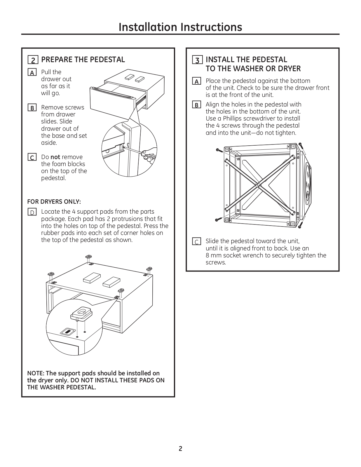
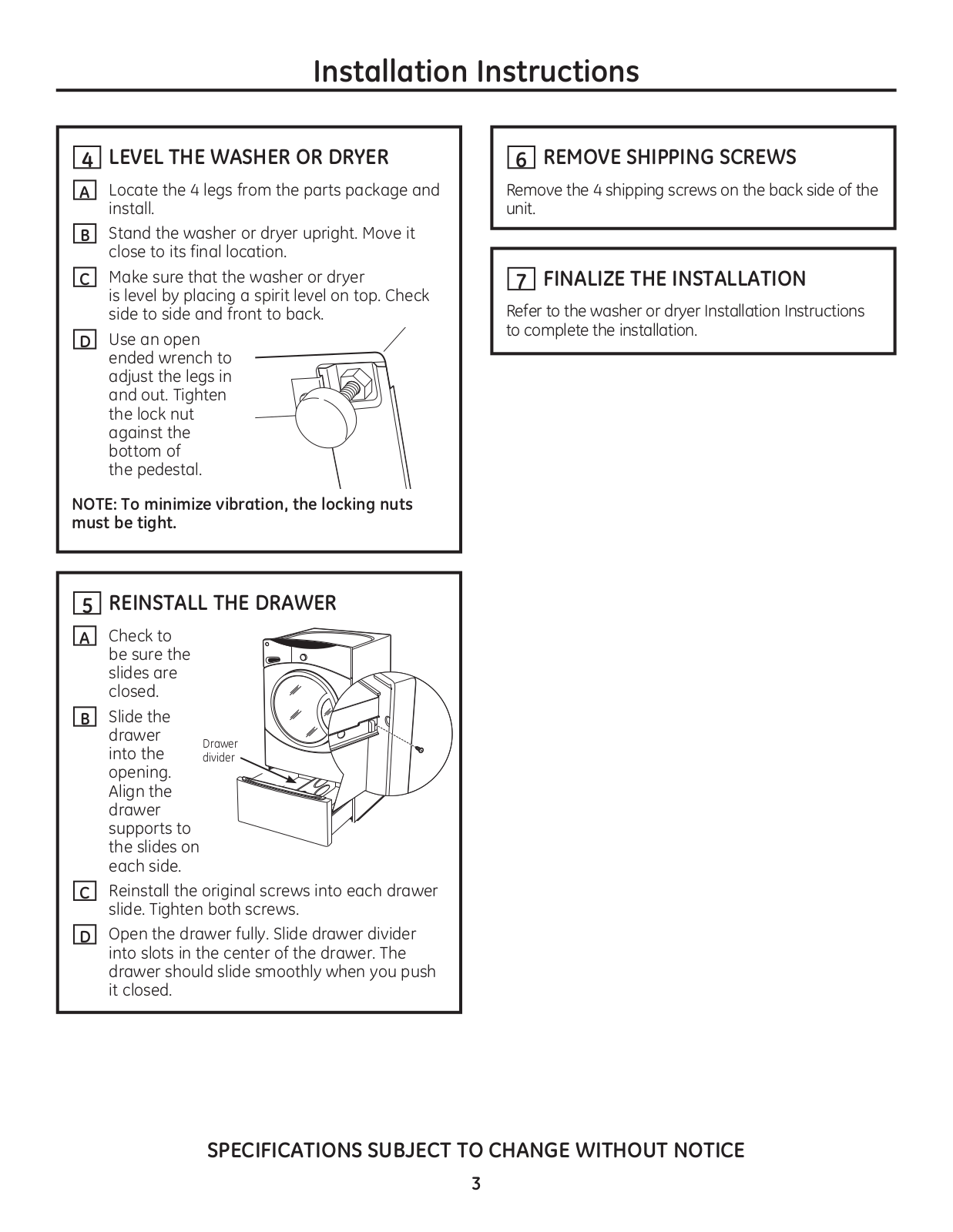
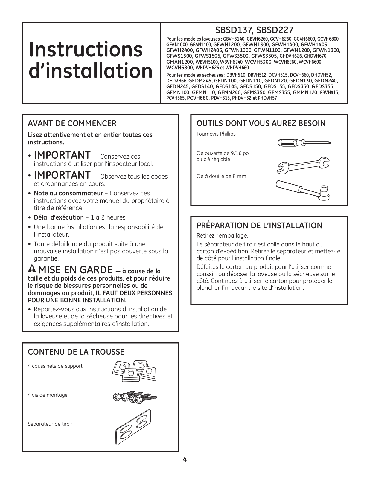
GE SBSD137HWW, SBSD137HBB Installation Guide
...
GE Installation Guide
Download
Text View
Picture View
Page 1
Page 2
Page 3
Page 4
Page 5
Page 6
Page 7
Page 8
Page 9
Page 10
Page 11
Page 12
Loading...
+
hidden pages
Unhide
You need points to download manuals.
1 point = 1 manual.
You can buy points or you can get point for every manual you upload.
Buy points
Upload your manuals
 Loading...