

Page 1
GE
Grid Solutions
GE Reason Switches
Industrial Managed Ethernet Switches
Technical Manual
T1000 Platform Hardware Version: A
T1000 Platform Software Version: 03
S20 Platform Hardware Version: B
S20 Platform Software Version: 06
Publication Reference: REASON-SWITCHES-TM-EN-3.3
imagination at work
Page 2

Page 3

CONTENTS
Chapter 1: Introduction 13
1 Foreword 13
1.1 Target Audience 13
1.2 Nomenclature 14
1.3 Acronyms and Abbreviations 14
2 Product Scope 18
3 Unpacking 19
4 Available models 20
4.1 T1000 20
4.2 S2020 20
4.3 S2024G 20
5 Key Features 21
6 Compliance 23
6.1 Standard Compliance 23
6.2 EMC Compliance 23
6.3 Product Safety 23
6.4 R&TTE Compliance 24
7 Ordering Options 25
7.1 S2020 25
7.2 S2024G 26
7.3 T1000 27
Chapter 2: Safety Information 29
1 Health and Safety 29
2 Symbols 31
3 Installation, Commissioning and Servicing 32
3.1 Lifting Hazards 32
3.2 Electrical Hazards 32
3.3 Fusing Requirements 34
3.4 Equipment Connections 34
3.5 Pre-energisation Checklist 36
3.6 Peripheral Circuitry 37
3.7 Upgrading/Servicing 37
4 Decommissioning and Disposal 38
Chapter 3: Hardware Design 39
1 Hardware Composition 39
2 Mechanical Implementation 40
3 Hardware Architecture 42
4 Communication port connections 43
Chapter 4: Functions 44
1 System management 44
Page 4

1.1 System Information 44
1.2 IP Information 45
1.3 NTP Synchronization 45
1.4 Time zone 46
1.5 Log 46
2 Ports 48
3 Security 50
3.1 SNMP Protocol 51
4 Aggregation 53
5 Loop Protection 56
5.1 Loop Fundamentals 56
5.2 Loop Protection 57
6 Spanning Tree Protocol 59
6.1 Spanning Fundamentals 59
6.2 STP Protocol 62
6.3 RSTP Protocol 64
6.4 MSTP Protocol 67
6.5 UltraRSTP 69
7 IPMC 71
7.1 IP Multicast (IPMC) 71
7.2 IGMP Snooping 72
7.3 MLD Snooping 74
8 MAC Table 76
9 Virtual LAN 79
9.1 Legacy LAN Technology 79
9.2 Virtual LAN Basics 80
9.3 LAN in Modern Power System Communication 83
9.4 IEEE 802.1Q Switch operation concepts 84
9.5 Reason Switches Operation 86
10 Quality of Service (QoS 89
10.1 Quality of Service Basics 89
10.2 Class-of-Service (CoS) Bits QoS 91
10.3 Differentiated Service Code Point (DSCP) 94
10.4 GE Reason Switches QoS Capabilities 96
11 Mirroring 101
12 Precision Time Protocol (PTP) 104
12.1 Timing Requirements for Power System Applications 104
12.2 Precision Time Protocol (PTP) Functional 105
12.3 PTP in GE Reason Switches 108
Chapter 5: Interfaces 110
1 Signalizing Leds 110
2 Reboot Button (Only for T1000) 112
3 Hardware Reset 113
4 Dry-Contact Relay 114
5 Communication Interfaces 115
Page 5

6 Communication Protocols 116
6.1 HTTP/HTTPS 116
6.2 SSH 116
6.3 Telnet 119
Chapter 6: Operation 122
1 Energizing 122
2 Local Operation – USB Interface 123
3 Remote Operation – Ethernet Interface 126
Chapter 7: Configuration 129
1 Configuration overview 129
2 System Management Setting 130
2.1 System Management Setting 130
2.2 IP Services 130
2.3 NTP Synchronization 134
2.4 Time Configuration 134
2.5 Log 136
3 Port Setting 138
4 Security Settings 142
4.1 General Security Settings 142
4.2 SNMP Setting 149
5 Aggregation Settings 157
5.1 Static Aggregation Setting 157
5.2 LACP Settings 158
6 Loop Protection Settings 160
7 Spanning Tree Settings 162
8 IPMC Setting 171
8.1 IPMC Profile 171
8.2 IPMC 174
9 MAC table Settings 183
10 VLAN Settings 185
11 QoS Settings 190
11.1 Port Classification 190
11.2 Port Policing 192
11.3 Queue Policing 193
11.4 Port Scheduler 193
11.5 Port Shaping 196
11.6 Port Tag Remarking 198
11.7 Port DSCP 200
11.8 DSCP-Based QoS 201
11.9 DSCP Translation 202
11.10 DSCP Classification 202
11.11 QoS Control List 203
11.12 Storm Policing 209
11.13 WRED 211
Page 6

12 Mirroring Settings 213
13 PTP Settings 217
14 Application Examples 221
14.1 Configuring VLANs in a Digital Substation Network 221
14.2 RSTP Configuring in a Ring Network Topology 229
14.3 PTP Transparent Clock 231
Chapter 8: Monitoring 235
1 System Management 235
2 Ports 238
3 Security 241
4 Aggregation 244
5 Loop Protection 246
6 Spanning Tree 247
7 IPMC 250
8 MAC Table 253
9 VLAN 254
10 PTP 255
Chapter 9: Installation 257
1 Functional Overview 257
1.1 Highlights 257
1.2 Human Machine Interface Descriptions 261
2 Mounting 263
2.1 Rack Mounting 263
2.2 Panel and Rail Mouting 264
3 Power Connections 266
4 Communications Ports 267
4.1 Electrical Ethernet Ports (RJ45) 267
4.2 Fixed Fiber Optics Transceiver (FDDI) 267
4.3 SFP Pluggable Transceiver 268
5 Dry Contact Alarm (Failsafe) 270
6 Preventive Maintenance Actions 271
6.1 Preventive Actions 271
Chapter 10: Maintenance and Troubleshooting 275
1 Network Diagnostics 275
1.1 Ping 275
1.2 Link OAM 276
1.3 Ping6 276
1.4 VeriPHY 278
2 Software Restart 280
3 Software Management 281
4 Configuration 283
5 Troubleshooting 286
6 Equipment Return 290
Page 7

7 Instructions for Equipment Repair Service 291
Chapter 11: Technical Specifications 292
1 Power Supply 292
2 Failsafe Relay 293
3 Networking Standards Supported 294
4 RJ45 Ethernet (10/100/1000 Mbps) Port 295
5 Optical Transceivers (100/1000 Mbps) 296
6 Operating Environment 297
7 T1000 Dimensions 298
8 S2020 and S202G Dimensions 299
9 Ingress Protection 300
9.1 Front Mounting 300
9.2 Rear Mounting 300
9.3 Pollution Degree 300
10 Insulation, EMI and Environmental Tests 301
10.1 Insulation Tests 301
10.2 Type Tests 301
Page 8

Table of Figures
Figure 1: T1000 Communication modules 39
Figure 2: T1000 Switch 40
Figure 3: S2020 Switch 40
Figure 4: S2024G Switch 41
Figure 5: Hardware architecture overview 42
Figure 6: NTP Time Protocol Mechanism 46
Figure 7: NTP Syslog Message Basics 47
Figure 8: Ports at a Transparent Bridge 48
Figure 9: Example of the SNMP management architecture 52
Figure 10: Comparison between common and aggregated links speed 53
Figure 11: Link failure behavior of an aggregated link 54
Figure 12: Load balancing in aggregated links 55
Figure 13: Bridge Loop 56
Figure 14: Usage situations for Loop Protection 57
Figure 15: BPDU Packet 59
Figure 16: Ring topology LAN and possible paths for data traffic from IED A to IED B 60
Figure 17: Example of a loop-topology showing bridge 61
Figure 18: Logical topology after the Spanning Tree protocol was executed 61
Figure 19: Port states in the Spanning Tree Protocol 62
Figure 20: STP protocol mechanism and maximum port changing time 63
Figure 21: Port states when STP protocol is used in a ring physical topology 64
Figure 22: Failure on the designated link of the Spanning tree 64
Figure 23: Reconfigured topology after a designated link failure 64
Figure 24: RSTP protocol mechanism 65
Figure 25: RSTP port status in a loop topology 66
Figure 26: RSTP edge and truck ports 66
Figure 27: BPDU flag field at RSTP protocol 67
Figure 28: MSTP regions and legacy RSTP LAN connection 68
Figure 29: CIST roots an MSTP regions and legacy RSTP LAN 69
Figure 30: MSTP regions behavior using RSTP protocol 69
Figure 31: RSTP recovery table 70
Figure 32: Network fault recovery using GE Reason Switches 70
Page 9

Figure 33: Unicast and Broadcast communication 71
Figure 34: Multicast communication 72
Figure 35: IGMP protocol mechanism 73
Figure 36: IGMP Snooping at a given LAN 74
Figure 37: Ethernet frame 76
Figure 38: Address a table at a given Switch 77
Figure 39: Forwarding traffic in an Ethernet switch 77
Figure 40: LAN access restriction with MAC address configuration 78
Figure 41: Different LAN from different departments 79
Figure 42: addition of new hosts to the legacy VALN-unaware equipment 80
Figure 43: Physical topology of the addition of new hosts with VLAN-aware equipment
81
Figure 44: Logical topology of the addition of new hosts with VLAN-aware equipment
81
Figure 45: 802.1Q Ethernet frame 82
Figure 46: Typical topology in power system communication environment 84
Figure 47: Logical topology of typical power system communication environment 84
Figure 48: Traffic flow inside an 802.1Q switch 85
Figure 49: Traffic in an oversized 90
Figure 50: Traffic of incoming data higher than the port at the switch can process 90
Figure 51: Network with prioritization of traffic 91
Figure 52: CoS bits inside and 802.1Q frame 92
Figure 53: Traffic type acronyms, show in section l.4 on the IEEE 802.1Q 92
Figure 54: CoS classification as shown in IEC 61850-90-4 Technical Report, section
D.2.6 93
Figure 55: IP Header frame and Differentiated Service Code Point explained 94
Figure 56: Mapping of applications for service levels, shown in section D.2.7 of the IEC
61850-90-4 Technical Report 94
Figure 57: List of DSCP code point field values, shown in section D.2.9 of the IEC 61850-
90-4 Technical Report 95
Figure 58: Example of DSCP to CoS mapping, shown in section D.2.9 of the IEC61850-
90-4 Technical Report 95
Figure 59: CoS queues and remarking functions 97
Figure 60: DSCP queues and translation functions 98
Figure 61: Port Mirroring Being Executed by a Switch 101
Figure 62: Port Mirroring in One Switch 102
Page 10

Figure 63: Port Mirroring in Many Switch 102
Figure 64: Data Monitor Flow Network 103
Figure 65: Synchronization classes, shown at IEC 61850-90-4 Technical Report, section
14.1 105
Figure 66: PTP network 106
Figure 67: PTP protocol mechanism 107
Figure 68: HMI LED matrix of T1000 Switches 110
Figure 69: HMI LED matrix of S2020 and S2024G Switches 111
Figure 70: Reboot button 112
Figure 71: Failsafe dry-contact relay 114
Figure 72: Example of HTTP or HTTPS first screen at a given web browser 116
Figure 73: Main menu at the SSH interface 118
Figure 74: Main menu at the Telnet interface 121
Figure 75: T1000 Power Supply Connector 122
Figure 76: S2020 and S2024G Power Supply Connector 122
Figure 77: B-type USB connector at Reason Switches 123
Figure 78: Main menu at the Telnet interface 125
Figure 79: Ethernet RJ45 connector at Reason Switches 126
Figure 80: Example of HTTP or HTTPS first screen at a given web browser 127
Figure 81: DPL level usage 212
Figure 82: Topology to be configured in a VLAN environment 221
Figure 83: Topology to be configured in a RSTP environment 230
Figure 84: Topology to be configured in a PTP environment 231
Figure 85: RJ45 port 262
Figure 86: Front mounting: Cabinet orientation for rack mounting 263
Figure 87: Rear mounting: Cabinet orientation for rack mounting 264
Figure 88: Mounting sites for rack adapters 264
Figure 89: Panel / DIN Rail front mounting diagram 265
Figure 90: T1000 (left) and S2020/S2024G (right) Power Supply Connector 266
Figure 91: RJ45 Ethernet Port 267
Figure 92: FDDI transceiver 268
Figure 93: SFP transceiver 268
Figure 94: Removal direction of the SFP transceiver 269
Figure 95: Insertion module of the SFP transceiver 269
Figure 96: Failsafe Relay 270
Page 11

Figure 97: T1000 dimensions 298
Figure 98: S2020 and S2024G dimensions 299
Page 12

Page 13

GE Reason Switches
Industrial Managed Ethernet Switch
Chapter 1: Introduction
This chapter provides some general information about the technical manual and an
introduction to the device(s) described in this technical manual.
1 Foreword
This technical manual provides a functional and technical description of GE Reason
Switches, as well as a comprehensive set of instructions for using the device. The
level at which this manual is written assumes that you are already familiar with
protection engineering and have experience in this discipline. The description of
principles and theory is limited to that which is necessary to understand the product.
We have attempted to make this manual as accurate, comprehensive and userfriendly as possible. However, we cannot guarantee that it is free from errors. Nor
can we state that it cannot be improved. We would therefore be very pleased to hear
from you if you discover any errors, or have any suggestions for improvement. Our
policy is to provide the information necessary to help you safely specify, engineer,
install, commission, maintain, and eventually dispose of this product. We consider
that this manual provides the necessary information, but if you consider that more
details are needed, please contact us.
All feedback should be sent to our contact centre via the following URL:
http://www.gegridsolutions.com/alstomenergy/grid/grid/contactcentre
1.1 Target Audience
This manual has been designed for all professionals charged with installing,
commissioning, maintaining, troubleshooting, or operating any of the products within
the specified product range. This includes installation and commissioning personnel
who will be responsible for operating the product. The level at which this manual is
written assumes that installation and commissioning personnel have knowledge of
handling electronic equipment and a thorough knowledge of Ethernet switches and
associated equipment.
Page 14

GE Reason Switches
Chapter 1 – Introduction
14
REASON SWITCHES-TM-EN-3
1.2 Nomenclature
Due to the technical nature of this manual, many special terms, abbreviations and
acronyms are used throughout the manual. Some of these terms are well-known
industry-specific terms while others may be special product-specific terms used by
GE Grid Solutions. The first instance of any acronym or term used in a particular
chapter is explained. In addition, a separate glossary is available on the GE website,
or from the GE contact centre.
We would like to highlight the following changes of nomenclature however:
British English is used throughout this manual.
The British term 'Earth' is used in favour of the American term 'Ground'.
1.3 Acronyms and Abbreviations
BC
Boundary Clock
BPDU
Bridge Protocol Data Unit
CSMA/CD
Carrier Sense Multiple Access with Collision Detection
CPU
Central Processing Unit
CoS
Class-of-Service
IEC TR 61850-904
Communication networks and systems for power utility
automation - Part 90-4: Network engineering guidelines
UTC
Universal Time Coordinated
DST
Daylight Saving Time
DSCP
Differentiated Services Code Point
DNS
Domain Name Server
DHCP
Dynamic Host Configuration Protocol
EMC
Electromagnetic compatibility
E2E
End-to-end
ECN
Explicit Congestion Notification
FCS
Frame Check Sequence
Page 15

Chapter 1 – Introduction
GE Reason Switches
REASON SWITCHES-TM-EN-3
15
Gbps
Gigabits per second
GPS
Global Positioning System
GMC
Grandmaster Clock
HRC
High Rupture Capacity
HMI
Human-Machine Interface
HTTP
Hypertext Transfer Protocol
HTTPS
Hypertext Transfer Protocol Secure
GOOSE
IEC 61850 - Generic Object Oriented Substation Event
SV
IEC 61850 - Sampled Values
IEC 61850-9-2LE
Implementation guideline for Digital Interface to Instrument
Transformers using IEC 61850-9-2
IEEE
Institute of Electrical and Electronics Engineers
IED
Intelligent Electronic Device
IRIG
Inter Range Instrumentation Group
IEC
International Electrotechnical Commission
ICMPv6
Internet Control Message Protocol version 6
IGMP
Internet Group Management Protocol
IP
Internet Protocol
IPMC
IP Multicast
LED
Light Emitting Diode
LLDP
Link Layer Discovery Protocol
LAN
Local Area Network
LVD
Low Voltage Directive
MIB
Management Information Base, used by SNMP protocol
MMS
Manufacturing Message Specification
MAC
Media Access Control
Mbps
megabits per second
Page 16

GE Reason Switches
Chapter 1 – Introduction
16
REASON SWITCHES-TM-EN-3
MCB
Miniature Circuit Breaker
MLD
Multicast Listener Discovery
MSTI
Multiple Spanning Tree Instance
MSTP
Multiple Spanning Tree Protocol (IEEE 802.1Q)
NIC
Network Interface Card
NTP
Network Time Protocol
NC
Normally Close
NO
Normally Open
OSI
Open Systems Interconnection model
P2P
Peer-to-peer
PPE
Personal Protective Equipment
PDC
Phasor Data Concentrator
PMU
Phasor Measurement Unit
PVID
Port VLAN Identifier
PTP
Precision Time Protocol (IEEE 1588)
PCP
Priority Code Point
PCT
Protective Conductor Terminal
PPS
Pulse per second
QoS
Quality-of-Service
R&TTE
Radio and Telecommunications Terminal Equipment
RSTP
Rapid Spanning Tree Protocol (IEEE 802.1D)
RADIUS
Remote Authentication Dial In User Service
RMON
Remote Network Monitoring
RFC
Request For Comments
SSH
Secure Shell
SSL
Secure Sockets Layer
VLAN ID
See VID
Page 17

Chapter 1 – Introduction
GE Reason Switches
REASON SWITCHES-TM-EN-3
17
SNMP
Simple Network Management Protocol
STP
Spanning Tree Protocol (IEEE 802.1D)
TACACS+
Terminal Access Controller Access Control System Plus
TCP
Transmission Control Protocol
TC
Transparent Clock
ToS
Type-of-Service
USB
Universal Serial Bus
UTP
Unshielded twisted pair
UDP
User Datagram Protocol
VLAN
Virtual LAN (IEEE 802.1Q)
VID
VLAN Identifier
WRED
Weighted Random Early Detection
WAMS
Wide Area Monitoring System
CLI
Command Line Interface
PDU
Protocol Data Units
CIST
Common Internal Spanning Tree
DPL
Drop Precedence Level
PCP
Priority Coded Point
DEI
Drop Eligible Indicator
DP
Drop Precedence
QCE
QoS Control Entry
QCL
QoS Control List
LACP
Link Aggregation Control Protocol
FDDI
Fixed Distributed Data Interface
SFP
Small-form Pluggable
ICMP
Internet Control Message Protocol
Page 18

GE Reason Switches
Chapter 1 – Introduction
18
REASON SWITCHES-TM-EN-3
2 Product Scope
GE Reason Switches are managed switches with modular communication interfaces
designed for harsh environment environments, such as power systems and industry
applications. Developed to be used in IEC 61850 networks, Reason Switches provide
flexibility, reliability and robustness in IED interconnections. Precision timing
synchronization of the IEDs can be obtained using the IEEE 1588 v2 protocol (PTP).
For IEC 61850 network applications, Reason Switches are able to perform traffic
isolation of Sampled Values (IEC 61850-9-2LE), GOOSE messages, PTP synchronizing
protocol and other messages using virtual LANs (VLANs). Switch traffic and ports
monitoring is performed using the SNMP protocol, and loop-based topologies, such
as ring topology, can be monitored and reconfigured using the RSTP (IEEE 802.1D)
protocol.
Packet switched transmission in the switches is totally done by hardware, which
ensures agility and maximum reliability even when interconnecting IEDs to distinct
interfaces and speeds.
The switches configuration may be done through interactive mode of text
commands (SSH and Telnet) or in a friendly graphic environment (HTTP or HTTPS) with
native or remote authentication (RADIUS and TACACS+). Statistical data collection
can be obtained using SNMP v2/v3 protocol. Communication interfaces are the
Ethernet port or a dedicated USB-2.0 port.
Critical applications can benefit from the optional redundant power supply for even
greater uptime and reliability. A dry-contact relay is available in Reason Switches to
indicate a failsafe alarm to the supervisory system when an interface communication
becomes unavailable or the equipment is missing of its power supplies.
Page 19

Chapter 1 – Introduction
GE Reason Switches
REASON SWITCHES-TM-EN-3
19
3 Unpacking
Unpack the equipment carefully and make sure that all accessories and cables are
put away so they will not be lost.
Check the contents against the packing list. If any of the contents listed is missing,
please contact GE immediately (see contact information at the beginning of this
manual).
Examine the equipment for any shipping damage. If the unit is damaged or fails to
operate, notify the shipping company immediately. Only the consignee (the person or
company receiving the unit) can file a claim against the carrier for occasional
shipping damages.
We recommend that the user retain the original packing materials for use in case of
need to transport or ship the equipment at some future time.
Page 20

GE Reason Switches
Chapter 1 – Introduction
20
REASON SWITCHES-TM-EN-3
4 Available models
4.1 T1000
T1000 is a managed switch and supports both NTP, operating as NTP client, and PTP,
used for IED synchronization.
The modular conception of T1000 switch allows up to 12 Ethernet ports (6 sets of 2
interfaces) supporting copper Ethernet communication (10/100/1000 Mpbs) and
Fibre Optic links (100/1000 Mpbs). For optical interface, ST (100 Mbps) and LC
(100/1000 Mbps) are available. LC Fibre links support multimode or single mode fibre
optics, and ST Fibre links support only multimode fibre optics.
Communication interfaces can be replaced or changed in the field with the
equipment in the panel.
4.2 S2020
The S2020 is a fast control Ethernet switch designed for less critical applications in
industry and power systems, such as the connection of high level equipment in the
automation architecture.
S2020's conception allows up to 20 Fast Ethernet ports or up to 16 Fast Ethernet
ports plus 4 Gigabit ports. The ports are in a module, containing 4 ports each, which
support copper Ethernet communication or LC connector Optical Fiber links
(multimode or single mode optical fiber).
S2020 only supports NTP synchronization protocol (client operation). If PTP is
required, refer to T1000 or S2024G.
4.3 S2024G
The S2024G is a managed gigabit Ethernet switch designed for applications that
request an increased number of Ethernet ports and Gigabit connection to most of
the nodes. The S2024G allows up to 24 Gigabit Ethernet interfaces operating
simultaneously.
S2024G supports IEEE 1588 v2 protocol (PTP) used for IED synchronization. In
transparent mode (TC), all ports support PTP by using time correction performed in
software (operation in two-step mode). In Boundary Clock (BC) mode up to 2 ports
can be used as a synchronizing input, leaving the remaining ports to be programmed
as outputs. S2024G may also operate as a NTP client.
Copper Ethernet communication (10/100/1000 Mpbs) and LC connector Optical Fiber
links (100/1000 Mpbs) are available. Optical Fiber links support multimode or single
mode optical.
Page 21

Chapter 1 – Introduction
GE Reason Switches
REASON SWITCHES-TM-EN-3
21
5 Key Features
Packet transmissions done by hardware, with a maximum switching capacity
(throughput) of 48 Gbps;
Automatic learning, auto-negotiation and automatic detection/treatment of
polarity at the copper ports (RJ45 connectors);
Store-and-forward packet switching;
Support to IPv4 and IPv6 protocols (Multicast, Unicast and Broadcast);
Storm detection and control (Multicast, Unicast and Broadcast storm types);
SSH text mode configuration on a safe connection;
SSL graphic mode configuration on a safe connection;
Native and remote authentication and authorization through RADIUS and
TACACS+;
Remote monitoring through RMON;
SNMP v1/v2c/v3 traffic mirroring and monitoring functions;
IP multicast management through IGMP v2/v3 (for IPv4 applications) and MLD
v1/v2 (for IPv6 applications);
VLAN traffic segregation (IEEE 802.1Q), and up to 4095 VLANs allowed;
Traffic prioritization (up to 8 Class of Service levels) using QoS (IEEE 802.1Q);
Loop detection and protection through Spanning-tree protocols: STP, RSTP (IEEE
802.1D) and MSTP (IEEE 802.1Q);
Loop detection and protection function without Spanning-tree protocols;
Automatic loop detection with Log and/or Shutdown port;
Automatic topology detection (ring or mixed-topologies which use redundant
path) and reconfiguration in case of loop detected;
Internal clock synchronization using up to 5 NTP time servers;
Operation as NTP-client;
Page 22

GE Reason Switches
Chapter 1 – Introduction
22
REASON SWITCHES-TM-EN-3
IEEE 1588v2 compliant (Precision Time Protocol – PTP) at all ports (except on
S2020);
PTP operation as Transparent Clock (TC, P2P or E2E delay mechanism
calculation) or Boundary Clock (BC);
USB 2.0 communication port for local configuration;
Dry-contact relay for external signalization failsafe alarm.
Page 23

Chapter 1 – Introduction
GE Reason Switches
REASON SWITCHES-TM-EN-3
23
6 Compliance
The device has undergone a range of extensive testing and certification processes to
ensure and prove compatibility with all target markets. A detailed description of
these criteria can be found in the Technical Specifications chapter.
6.1 Standard Compliance
Compliance with the European Commission Directive on EMC and LVD is
demonstrated by self-certification against international standards.
6.2 EMC Compliance
Compliance with IEC 60255-26:2013 was used to establish conformity.
6.3 Product Safety
Compliance with IEC 60255-27:2013 was used to establish conformity.
Protective Class
IEC60255-27:2013 Protective Class 1. This equipment requires a protective conductor
(ground) to ensure user safety.
Installation category
IEC 60255-27:2013 Installation category III (Overvoltage Category III). Equipment in
this category is qualification tested at 5kV peak, 1.2/50 µS, 500 Ohms, 0.5 J, between
all supply circuits and ground, and also between independent circuits.
Environment
IEC 60068-2-1, IEC 60068-2-2, IEC 60068-2-30, IEC 60068-2-14, IEC 60255-21-1, IEC
60255-21-2. The equipment is intended for indoor use only. If it is required for use in
an outdoor environment, it must be mounted in a specific cabinet or housing which
will enable it to meet the requirements of IEC 60529 with the classification of degree
of protection IP54.
Page 24

GE Reason Switches
Chapter 1 – Introduction
24
REASON SWITCHES-TM-EN-3
6.4 R&TTE Compliance
R&TTE - Radio and Telecommunications Terminal Equipment directive 99/5/EC.
Conformity is demonstrated by compliance with both the EMC directive and the Low
Voltage directive, to zero volts
Page 25
Chapter 1 – Introduction
GE Reason Switches
REASON SWITCHES-TM-EN-3
25
7 Ordering Options
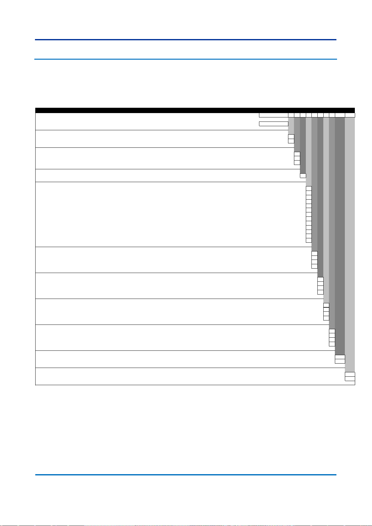
7.1 S2020
Issue F
Variants Order Number
1-5 6 7 8 9 10 11 12 13 14-15 16-17
Model Type
S2020 Modular Managed Ethernet Switch S2020
Power Supply 1
24-48 Vdc 1
100-250 Vdc / 110-240 Vac 3
Power Supply 2
24-48 Vdc 1
100-250 Vdc / 110-240 Vac 3
Not installed X
Mounting Options
19” Rack Mount / Rear Mount P
Interface Module 1
Four 1 Gbps RJ45 copper 10/100BASE-TX/1000BASE-T Ethernet ports A
Four slots for SFP transceivers B
Four 1 Gbps LC-type connector multi mode fiber 1000BASE-SX Ethernet for up to 0.5 km C
Four 1 Gbps LC-type connector single mode fiber 1000BASE-LX Ethernet for up to 10 km D
Four 1 Gbps LC-type connector single mode fiber 1000BASE-ZX Ethernet for up to 40 km E
Four 1 Gbps LC-type connector single mode fiber 1000BASE-ZX Ethernet for up to 80 km F
Four 100 Mbps LC-type connector multi mode fiber 100BASE-FX Ethernet for up to 2 km H
Four RJ45 copper 10/100BASE-TX I
Four 1 Gbps RJ45 SFP Transceivers 10/100BASE-TX/1000BASE-T Ethernet ports (Not CE marked) J
Two 1 Gbps RJ45 SFP Transceivers 10/100BASE-TX/1000BASE-T Ethernet ports + Two 1 Gbps LC-type connector multi mode fiber 1000BASE-SX Ethernet for up to 0.5 km K
Two 1 Gbps RJ45 SFP Transceivers 10/100BASE-TX/1000BASE-T Ethernet ports + Two 100 Mbps LC-type connector multi mode fiber 100BASE-FX Ethernet for up to 2 km
L
Two 1 Gbps LC-type connector multi mode fiber 1000BASE-SX Ethernet for up to 0.5 km + Two 100 Mbps LC-type connector multi mode fiber 100BASE-FX Ethernet for up to 2 km M
Not installed X
Interface Module 2
Four slots for SFP transceivers B
Four 100 Mbps LC-type connector multi mode fiber 100BASE-FX Ethernet for up to 2 km H
Four RJ45 copper 10/100BASE-TX I
Not installed X
Interface Module 3
Four slots for SFP transceivers B
Four 100 Mbps LC-type connector multi mode fiber 100BASE-FX Ethernet for up to 2 km H
Four RJ45 copper 10/100BASE-TX I
Not installed X
Interface Module 4
Four slots for SFP transceivers B
Four 100 Mbps LC-type connector multi mode fiber 100BASE-FX Ethernet for up to 2 km H
Four RJ45 copper 10/100BASE-TX I
Not installed X
Interface Module 5
Four slots for SFP transceivers B
Four 100 Mbps LC-type connector multi mode fiber 100BASE-FX Ethernet for up to 2 km H
Four RJ45 copper 10/100BASE-TX I
Not installed X
Firmware Version
Latest available firmware - 06 06
Firmware version number - 05 05
Hardware Design Suffix
Standard hardware release B
Alternate hardware release BL
Page 26
GE Reason Switches
Chapter 1 – Introduction
26
REASON SWITCHES-TM-EN-3
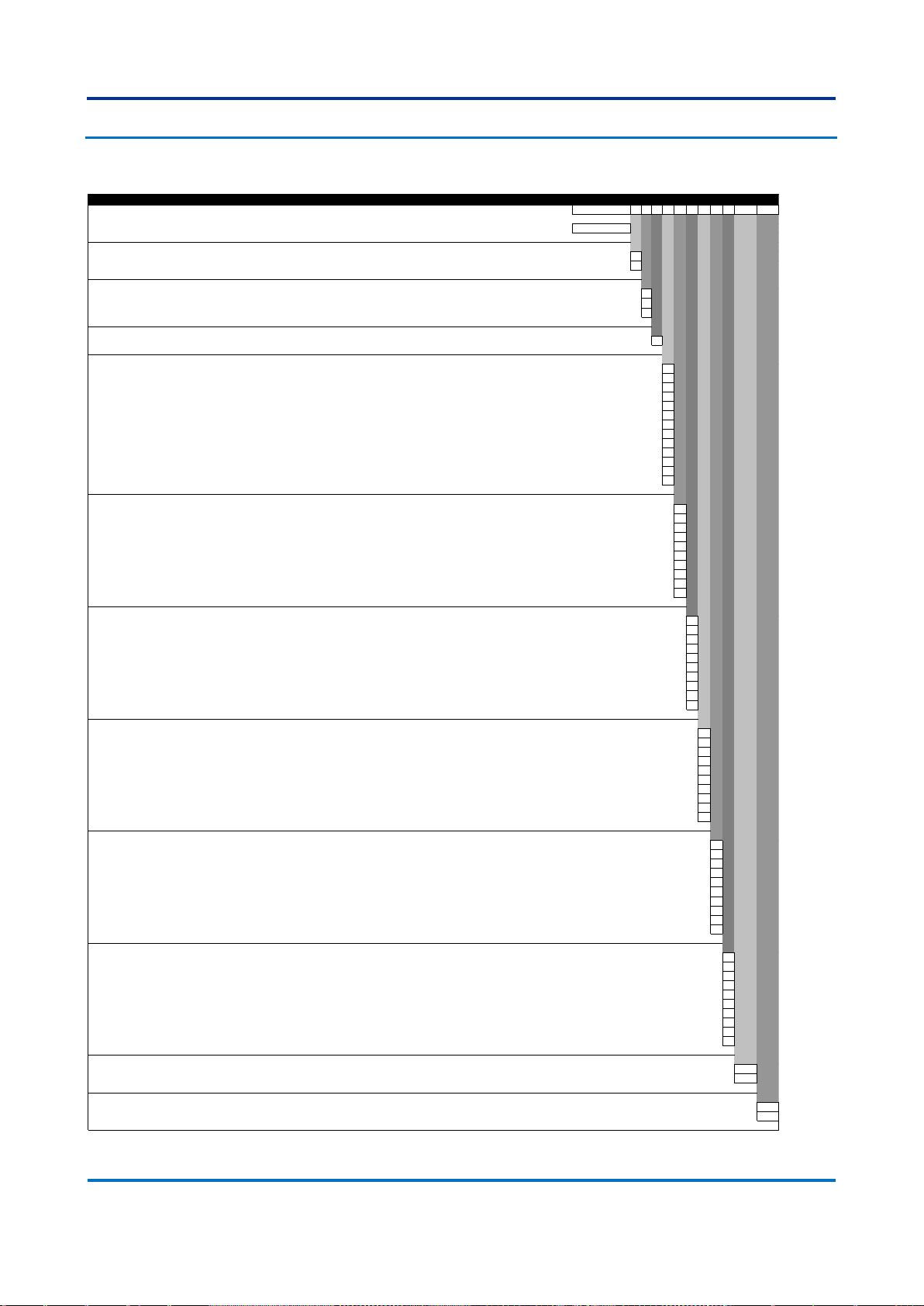
7.2 S2024G
Issue F
Variants Order Number
1-6 7 8 9 10 11 12 13 14 15 16-17 18-19
Model Type
S2024G Modular Managed Ethernet Switch S2024G
Power Supply 1
24-48 Vdc 1
100-250 Vdc / 110-240 Vac 3
Power Supply 2
24-48 Vdc 1
100-250 Vdc / 110-240 Vac 3
Not installed X
Mounting Options
19” Rack Mount / Rear Mount P
Interface Module 1
Four 1 Gbps RJ45 copper 10/100BASE-TX/1000BASE-T Ethernet ports A
Four slots for SFP transceivers B
Four 1 Gbps LC-type connector multi mode fiber 1000BASE-SX Ethernet for up to 0.5 km C
Four 1 Gbps LC-type connector single mode fiber 1000BASE-LX Ethernet for up to 10 km D
Four 1 Gbps LC-type connector single mode fiber 1000BASE-ZX Ethernet for up to 40 km E
Four 1 Gbps LC-type connector single mode fiber 1000BASE-ZX Ethernet for up to 80 km F
Four 100 Mbps LC-type connector multi mode fiber 100BASE-FX Ethernet for up to 2 km H
Four RJ45 copper 10/100BASE-TX I
Four 1 Gbps RJ45 SFP Transceivers 10/100BASE-TX/1000BASE-T Ethernet ports (Not CE marked) J
Two 1 Gbps RJ45 SFP Transceivers 10/100BASE-TX/1000BASE-T Ethernet ports + Two 1 Gbps LC-type connector multi mode fiber 1000BASE-SX Ethernet for up to 0.5 km K
Two 1 Gbps RJ45 SFP Transceivers 10/100BASE-TX/1000BASE-T Ethernet ports + Two 100 Mbps LC-type connector multi mode fiber 100BASE-FX Ethernet for up to 2 km L
Two 1 Gbps LC-type connector multi mode fiber 1000BASE-SX Ethernet for up to 0.5 km + Two 100 Mbps LC-type connector multi mode fiber 100BASE-FX Ethernet for up to 2 km M
Not installed X
Interface Module 2
Four 1 Gbps RJ45 copper 10/100BASE-TX/1000BASE-T Ethernet ports A
Four slots for SFP transceivers B
Four 1 Gbps LC-type connector multi mode fiber 1000BASE-SX Ethernet for up to 0.5 km C
Four 1 Gbps LC-type connector single mode fiber 1000BASE-LX Ethernet for up to 10 km D
Four 1 Gbps LC-type connector single mode fiber 1000BASE-ZX Ethernet for up to 40 km E
Four 1 Gbps LC-type connector single mode fiber 1000BASE-ZX Ethernet for up to 80 km F
Four 100 Mbps LC-type connector multi mode fiber 100BASE-FX Ethernet for up to 2 km H
Four RJ45 copper 10/100BASE-TX I
Four 1 Gbps RJ45 SFP Transceivers 10/100BASE-TX/1000BASE-T Ethernet ports (Not CE marked) J
Not installed X
Interface Module 3
Four 1 Gbps RJ45 copper 10/100BASE-TX/1000BASE-T Ethernet ports A
Four slots for SFP transceivers B
Four 1 Gbps LC-type connector multi mode fiber 1000BASE-SX Ethernet for up to 0.5 km C
Four 1 Gbps LC-type connector single mode fiber 1000BASE-LX Ethernet for up to 10 km D
Four 1 Gbps LC-type connector single mode fiber 1000BASE-ZX Ethernet for up to 40 km E
Four 1 Gbps LC-type connector single mode fiber 1000BASE-ZX Ethernet for up to 80 km F
Four 100 Mbps LC-type connector multi mode fiber 100BASE-FX Ethernet for up to 2 km H
Four RJ45 copper 10/100BASE-TX I
Four 1 Gbps RJ45 SFP Transceivers 10/100BASE-TX/1000BASE-T Ethernet ports (Not CE marked) J
Not installed X
Interface Module 4
Four 1 Gbps RJ45 copper 10/100BASE-TX/1000BASE-T Ethernet ports A
Four slots for SFP transceivers B
Four 1 Gbps LC-type connector multi mode fiber 1000BASE-SX Ethernet for up to 0.5 km C
Four 1 Gbps LC-type connector single mode fiber 1000BASE-LX Ethernet for up to 10 km D
Four 1 Gbps LC-type connector single mode fiber 1000BASE-ZX Ethernet for up to 40 km E
Four 1 Gbps LC-type connector single mode fiber 1000BASE-ZX Ethernet for up to 80 km F
Four 100 Mbps LC-type connector multi mode fiber 100BASE-FX Ethernet for up to 2 km H
Four RJ45 copper 10/100BASE-TX I
Four 1 Gbps RJ45 SFP Transceivers 10/100BASE-TX/1000BASE-T Ethernet ports (Not CE marked) J
Not installed X
Interface Module 5
Four 1 Gbps RJ45 copper 10/100BASE-TX/1000BASE-T Ethernet ports A
Four slots for SFP transceivers B
Four 1 Gbps LC-type connector multi mode fiber 1000BASE-SX Ethernet for up to 0.5 km C
Four 1 Gbps LC-type connector single mode fiber 1000BASE-LX Ethernet for up to 10 km D
Four 1 Gbps LC-type connector single mode fiber 1000BASE-ZX Ethernet for up to 40 km E
Four 1 Gbps LC-type connector single mode fiber 1000BASE-ZX Ethernet for up to 80 km F
Four 100 Mbps LC-type connector multi mode fiber 100BASE-FX Ethernet for up to 2 km H
Four RJ45 copper 10/100BASE-TX I
Four 1 Gbps RJ45 SFP Transceivers 10/100BASE-TX/1000BASE-T Ethernet ports (Not CE marked) J
Not installed X
Interface Module 6
Four 1 Gbps RJ45 copper 10/100BASE-TX/1000BASE-T Ethernet ports A
Four slots for SFP transceivers B
Four 1 Gbps LC-type connector multi mode fiber 1000BASE-SX Ethernet for up to 0.5 km C
Four 1 Gbps LC-type connector single mode fiber 1000BASE-LX Ethernet for up to 10 km D
Four 1 Gbps LC-type connector single mode fiber 1000BASE-ZX Ethernet for up to 40 km E
Four 1 Gbps LC-type connector single mode fiber 1000BASE-ZX Ethernet for up to 80 km F
Four 100 Mbps LC-type connector multi mode fiber 100BASE-FX Ethernet for up to 2 km H
Four RJ45 copper 10/100BASE-TX I
Four 1 Gbps RJ45 SFP Transceivers 10/100BASE-TX/1000BASE-T Ethernet ports (Not CE marked) J
Not installed X
Firmware Version
Latest available firmware - 06 06
Firmware version number - 05 05
Hardware Design Suffix
Standard hardware release B
Alternate hardware release BL
Page 27
Chapter 1 – Introduction
GE Reason Switches
REASON SWITCHES-TM-EN-3
27
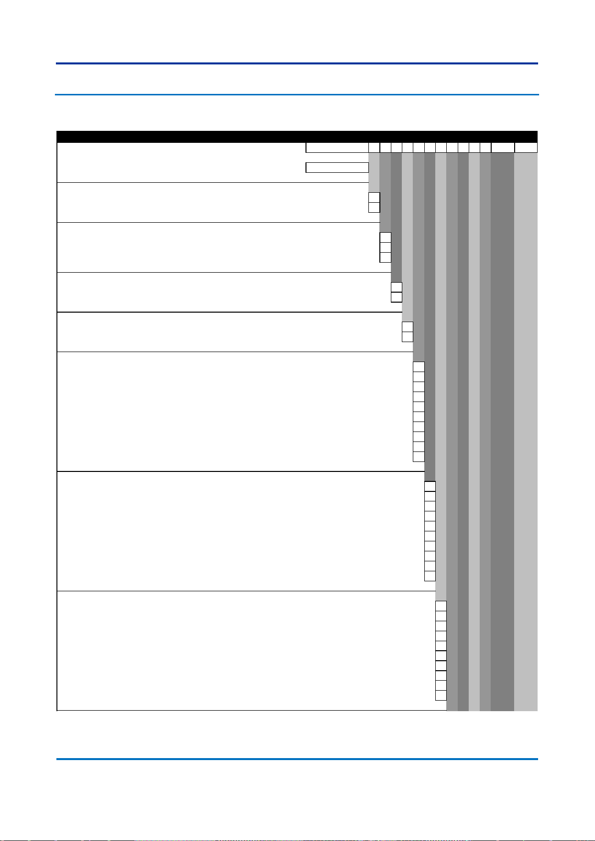
7.3 T1000
Variants
1-5 6 7 8 9 10 11 12 13 14 15 16 17-18 19-20
Model Type
T1000 Modular Managed Ethernet Switch Gigabit T1000
Power Supply 1
24-48 Vdc 1
100-250 Vdc / 110-240 Vac 3
Power Supply 2
24-48 Vdc 1
100-250 Vdc / 110-240 Vac 3
Not installed X
Mounting Options 1
Ethernet ports on the front F
Ethernet ports on the rear R
Mounting Options 2
Rack/Panel mounting P
DIN rail mounting D
Interface Module 1
Two 1 Gbps RJ45 copper 10/100BASE-TX/1000BASE-T Ethernet ports A
Two slots for SFP transceivers B
Two 1 Gbps LC-type connector multi mode fiber 1000BASE-SX Ethernet for up to 0.5 km C
Two 1 Gbps LC-type connector single mode fiber 1000BASE-LX Ethernet for up to 10 km D
Two 1 Gbps LC-type connector single mode fiber 1000BASE-ZX Ethernet for up to 40 km E
Two 1 Gbps LC-type connector single mode fiber 1000BASE-ZX Ethernet for up to 80 km F
Two 100 Mbps ST-type connector multi mode fiber 100BASE-FX Ethernet for up to 2 km G
Two 100 Mbps LC-type connector multi mode fiber 100BASE-FX Ethernet for up to 2 km H
Two 1 Gbps RJ45 SFP Transceivers 10/100BASE-TX/1000BASE-T Ethernet ports (Not CE marked) J
Not installed X
Interface Module 2
Two 1 Gbps RJ45 copper 10/100BASE-TX/1000BASE-T Ethernet ports A
Two slots for SFP transceivers B
Two 1 Gbps LC-type connector multi mode fiber 1000BASE-SX Ethernet for up to 0.5 km C
Two 1 Gbps LC-type connector single mode fiber 1000BASE-LX Ethernet for up to 10 km D
Two 1 Gbps LC-type connector single mode fiber 1000BASE-ZX Ethernet for up to 40 km E
Two 1 Gbps LC-type connector single mode fiber 1000BASE-ZX Ethernet for up to 80 km F
Two 100 Mbps ST-type connector multi mode fiber 100BASE-FX Ethernet for up to 2 km G
Two 100 Mbps LC-type connector multi mode fiber 100BASE-FX Ethernet for up to 2 km H
Two 1 Gbps RJ45 SFP Transceivers 10/100BASE-TX/1000BASE-T Ethernet ports (Not CE marked) J
Not installed X
Interface Module 3
Two 1 Gbps RJ45 copper 10/100BASE-TX/1000BASE-T Ethernet ports A
Two slots for SFP transceivers B
Two 1 Gbps LC-type connector multi mode fiber 1000BASE-SX Ethernet for up to 0.5 km C
Two 1 Gbps LC-type connector single mode fiber 1000BASE-LX Ethernet for up to 10 km D
Two 1 Gbps LC-type connector single mode fiber 1000BASE-ZX Ethernet for up to 40 km E
Two 1 Gbps LC-type connector single mode fiber 1000BASE-ZX Ethernet for up to 80 km F
Two 100 Mbps ST-type connector multi mode fiber 100BASE-FX Ethernet for up to 2 km G
Two 100 Mbps LC-type connector multi mode fiber 100BASE-FX Ethernet for up to 2 km H
Two 1 Gbps RJ45 SFP Transceivers 10/100BASE-TX/1000BASE-T Ethernet ports (Not CE marked) J
Not installed X
Order Number
Page 28
GE Reason Switches
Chapter 1 – Introduction
28
REASON SWITCHES-TM-EN-3
Issue I
Interface Module 4
Two 1 Gbps RJ45 copper 10/100BASE-TX/1000BASE-T Ethernet ports A
Two slots for SFP transceivers B
Two 1 Gbps LC-type connector multi mode fiber 1000BASE-SX Ethernet for up to 0.5 km C
Two 1 Gbps LC-type connector single mode fiber 1000BASE-LX Ethernet for up to 10 km D
Two 1 Gbps LC-type connector single mode fiber 1000BASE-ZX Ethernet for up to 40 km E
Two 1 Gbps LC-type connector single mode fiber 1000BASE-ZX Ethernet for up to 80 km F
Two 100 Mbps ST-type connector multi mode fiber 100BASE-FX Ethernet for up to 2 km G
Two 100 Mbps LC-type connector multi mode fiber 100BASE-FX Ethernet for up to 2 km H
Two 1 Gbps RJ45 SFP Transceivers 10/100BASE-TX/1000BASE-T Ethernet ports (Not CE marked) J
Not installed X
Interface Module 5
Two 1 Gbps RJ45 copper 10/100BASE-TX/1000BASE-T Ethernet ports A
Two slots for SFP transceivers B
Two 1 Gbps LC-type connector multi mode fiber 1000BASE-SX Ethernet for up to 0.5 km C
Two 1 Gbps LC-type connector single mode fiber 1000BASE-LX Ethernet for up to 10 km D
Two 1 Gbps LC-type connector single mode fiber 1000BASE-ZX Ethernet for up to 40 km E
Two 1 Gbps LC-type connector single mode fiber 1000BASE-ZX Ethernet for up to 80 km F
Two 100 Mbps ST-type connector multi mode fiber 100BASE-FX Ethernet for up to 2 km G
Two 100 Mbps LC-type connector multi mode fiber 100BASE-FX Ethernet for up to 2 km H
Two 1 Gbps RJ45 SFP Transceivers 10/100BASE-TX/1000BASE-T Ethernet ports (Not CE marked) J
Not installed X
Interface Module 6
Two 1 Gbps RJ45 copper 10/100BASE-TX/1000BASE-T Ethernet ports A
Two slots for SFP transceivers B
Two 1 Gbps LC-type connector multi mode fiber 1000BASE-SX Ethernet for up to 0.5 km C
Two 1 Gbps LC-type connector single mode fiber 1000BASE-LX Ethernet for up to 10 km D
Two 1 Gbps LC-type connector single mode fiber 1000BASE-ZX Ethernet for up to 40 km E
Two 1 Gbps LC-type connector single mode fiber 1000BASE-ZX Ethernet for up to 80 km F
Two 100 Mbps ST-type connector multi mode fiber 100BASE-FX Ethernet for up to 2 km G
Two 100 Mbps LC-type connector multi mode fiber 100BASE-FX Ethernet for up to 2 km H
Two 1 Gbps RJ45 SFP Transceivers 10/100BASE-TX/1000BASE-T Ethernet ports (Not CE marked) J
Not installed X
PTP Support
With PTP (IEEE 1588) support P
Without PTP (IEEE 1588) support X
Firmware Version
Latest available firmware - 03 03
Hardware Design Suffix
Standard hardware release A
Alternate hardware release AL
Page 29

GE Reason Switches
Industrial Managed Ethernet Switches
Chapter 2: Safety Information
This chapter provides information about the safe handling of the equipment. The
equipment must be properly installed and handled in order to maintain it in a safe
condition and to keep personnel safe at all times. You must be familiar with
information contained in this chapter before unpacking, installing, commissioning, or
servicing the equipment.
1 Health and Safety
Personnel associated with the equipment must be familiar with the contents of this
Safety Information.
When electrical equipment is in operation, dangerous voltages are present in certain
parts of the equipment. Improper use of the equipment and failure to observe
warning notices will endanger personnel.
Only qualified personnel may work on or operate the equipment. Qualified personnel
are individuals who are:
familiar with the installation, commissioning, and operation of the
equipment and the system to which it is being connected.
familiar with accepted safety engineering practises and are authorised to
energise and de-energise equipment in the correct manner.
trained in the care and use of safety apparatus in accordance with safety
engineering practises
trained in emergency procedures (first aid).
The documentation provides instructions for installing, commissioning and operating
the equipment. It cannot, however cover all conceivable circumstances. In the event
Page 30

GE Reason Switches
Chapter 2 – Safety Information
30
REASON SWITCHES-TM-EN-3
of questions or problems, do not take any action without proper authorisation. Please
contact your local sales office and request the necessary information.
Each product is subjected to routine production testing for Dielectric Strength and Protective Bonding Continuity
Page 31

Chapter 2 – Safety Information
GE Reason Switches
REASON SWITCHES-TM-EN-3
31
2 Symbols
Throughout this manual you will come across the following symbols. You will also
see these symbols on parts of the equipment.
Caution: Refer to equipment documentation. Failure to do
so could result in damage to the equipment
Risk of electric shock
Ground terminal. Note: This symbol may also be used for a
protective conductor (ground) terminal if that terminal is
part of a terminal block or sub-assembly.
Protective conductor (ground) terminal
Both direct and alternating current
Instructions on disposal requirements
The term 'Ground' used in this manual is the direct equivalent of the European term 'Earth'.
Page 32

GE Reason Switches
Chapter 2 – Safety Information
32
REASON SWITCHES-TM-EN-3
3 Installation, Commissioning and Servicing
3.1 Lifting Hazards
Many injuries are caused by:
Lifting heavy objects
Lifting things incorrectly
Pushing or pulling heavy objects
Using the same muscles repetitively
Plan carefully, identify any possible hazards and determine how best to move the
product. Look at other ways of moving the load to avoid manual handling. Use the
correct lifting techniques and Personal Protective Equipment (PPE) to reduce the risk
of injury.
3.2 Electrical Hazards
All personnel involved in installing, commissioning, or servicing
this equipment must be familiar with the correct working
procedures.
Consult the equipment documentation before installing,
commissioning, or servicing the equipment.
Always use the equipment as specified. Failure to do so will
jeopardise the protection provided by the equipment.
Removal of equipment panels or covers may
expose hazardous live parts. Do not touch until
the electrical power is removed. Take care when
there is unlocked access to the rear of the
equipment.
Isolate the equipment before working on the
terminal strips.
Page 33

Chapter 2 – Safety Information
GE Reason Switches
REASON SWITCHES-TM-EN-3
33
Use a suitable protective barrier for areas with
restricted space, where there is a risk of electric
shock due to exposed terminals.
Disconnect power before disassembling. Disassembly of the
equipment may expose sensitive electronic circuitry. Take
suitable precautions against electrostatic voltage discharge
(ESD) to avoid damage to the equipment.
NEVER look into optical fibres or optical output connections.
Always use optical power meters to determine operation or
signal level.
Testing may leave capacitors charged to dangerous voltage
levels. Discharge capacitors by reducing test voltages to zero
before disconnecting test leads.
If the equipment is used in a manner not specified by the
manufacturer, the protection provided by the equipment may
be impaired.
Operate the equipment within the specified electrical and
environmental limits.
Before cleaning the equipment, ensure that no connections are
energised. Use a lint free cloth dampened with clean water.
Integration of the equipment into systems shall not interfere
with its normal functioning.
The functioning of the device has been certified under the
circumstances described by the standards mentioned in
Error! Reference source not found. (item Type Tests). Usage of t
he equipment in different conditions from the specified in this
manual might affect negatively its normal integrity.
The equipment shall have all their rear connectors attached
even if they are not being used, in order to keep their levels of
ingress protection as high as possible
Page 34

GE Reason Switches
Chapter 2 – Safety Information
34
REASON SWITCHES-TM-EN-3
Never manipulate liquid containers near the equipment even
when it is powered off.
Avoid modification to the wiring of panel when the system is
running.
VT circuits must never be left short circuited.
3.3 Fusing Requirements
A high rupture capacity (HRC) fuse type with a maximum
current rating of 10 Amps and a minimum dc rating of 250 V dc
may be used for the auxiliary supply (for example Red Spot type
NIT or TIA). Alternatively a miniature circuit breaker (MCB) of
type C, 10A rating, compliant with IEC 60947-1 and IEC 60947-3
may be used.
Digital input circuits should be protected by a high rupture
capacity NIT or TIA fuse with maximum rating of 10 A, or
equivalent MCB as above. For safety reasons, current
transformer circuits must never be fused. Other circuits should
be appropriately fused to protect the wire used.
Reason devices contain an internal fuse for the power supply
which is only accessed by opening the product. This does not
remove the requirement for external fusing or use of an MCB as
previously mentioned. The ratings of the internal fuses are:
5 Amp, type T, 250V rating
CTs must NOT be fused since open circuiting them may produce
lethal hazardous voltages.
3.4 Equipment Connections
Page 35

Chapter 2 – Safety Information
GE Reason Switches
REASON SWITCHES-TM-EN-3
35
Terminals exposed during installation, commissioning
and maintenance may present a hazardous voltage
unless the equipment is electrically isolated.
Tighten M3 clamping screws of heavy duty terminal block
connectors to a nominal torque of 1.0 Nm.
Tighten captive screws of header-type (Euro) terminal blocks
to 0.5 Nm minimum and 0.6 Nm maximum.
Always use insulated crimp terminations for voltage and
current connections.
Always use the correct crimp terminal and tool according to
the wire size.
In order to maintain the equipment’s requirements for
protection against electric shock, other devices
connected to Reason Switches shall have protective class
equal or superior to Class 1.
Watchdog (self-monitoring) contacts are provided to indicate
the health of the device on some products. We strongly
recommend that you hard wire these contacts into the
substation's automation system, for alarm purposes.
Ground the equipment with the supplied PCT (Protective
Conductor Terminal).
Do not remove the PCT
Page 36

GE Reason Switches
Chapter 2 – Safety Information
36
REASON SWITCHES-TM-EN-3
The PCT is sometimes used to terminate cable
screens. Always check the PCT’s integrity after
adding or removing such ground connections.
The user is responsible for ensuring the integrity of
any protective conductor connections before
carrying out any other actions.
The PCT connection must have low-inductance and be as
short as possible.
All connections to the equipment must have a defined
potential. Connections that are pre-wired, but not used,
should be earthed, or connected to a common grouped
potential.
Pay extra attention to diagrams before wiring the
equipment. Always be sure that the connections are correct
before energizing the circuits.
3.5 Pre-energisation Checklist
Check voltage rating/polarity (rating label/equipment
documentation).
Check CT circuit rating (rating label) and integrity of
connections.
Check protective fuse or miniature circuit breaker (MCB)
rating.
Page 37

Chapter 2 – Safety Information
GE Reason Switches
REASON SWITCHES-TM-EN-3
37
Check integrity of the PCT connection.
Check voltage and current rating of external wiring,
ensuring it is appropriate for the application.
3.6 Peripheral Circuitry
Do not open the secondary circuit of a live CT
since the high voltage produced may be lethal
to personnel and could damage insulation.
Short the secondary of the line CT before
opening any connections to it.
Reason devices DO NOT feature any automatic CT shorting feature. Therefore external shorting of the CTs is mandatory. Check
the equipment documentation and wiring diagrams carefully.
3.7 Upgrading/Servicing
Do not insert or withdraw modules, PCBs or
expansion boards from the equipment while
energized, as this may result in damage to the
equipment. Hazardous live voltages would also be
exposed, endangering personnel.
Internal modules and assemblies can be heavy and
may have sharp edges. Take care when inserting or
removing modules into or out of the IED.
Page 38

GE Reason Switches
Chapter 2 – Safety Information
38
REASON SWITCHES-TM-EN-3
4 Decommissioning and Disposal
Before decommissioning, completely isolate the
equipment power supplies (both poles of any dc
supply). The auxiliary supply input may have
capacitors in parallel, which may still be charged. To
avoid electric shock, discharge the capacitors using
the external terminals before decommissioning.
Avoid incineration or disposal to water courses.
Dispose of the equipment in a safe, responsible and
environmentally friendly manner, and if applicable, in
accordance with country-specific regulations.
Page 39

GE Reason Switches
Industrial Managed Ethernet Switches
Chapter 3: Hardware Design
1 Hardware Composition
Main components in Reason Switches devices platform are as follows:
The housing, consisting of a front panel and connections at the rear;
The main processor module, consisting of the main CPU, memory, PHY
circuitry for interfacing between the link layer and physical layer, and
interfaces to the HMI module and failsafe relay;
A failsafe relay board, consisting of an output relay for signaling and a USB
communication port;
HMI board, consisting of LEDs to indicate port activity and speed and a
Reset button (only in T1000), used to manually restart switches manually;
Communication modules;
The failsafe relay board and HMI board are connected to the main processor module
by flat cables. Communication modules are connected directly to the main processor
module. T1000 switches are built with a board and connector that allow it to be
changed in field without the need of taking the switch off the panel, as shown in the
figure below. The communication module of S2020 and S2024G are connected to the
main processor module, as these switches don’t allow the user to change its
communication modules
Figure 1: T1000 Communication modules
Page 40

GE Reason Switches
Chapter 3 – Hardware Design
40
REASON SWITCHES-TM-EN-3
2 Mechanical Implementation
All GE Reason Switches have similar hardware architectures, the equipment housing
is composed by metalwork where the boards are fixed. After mounting, a cover is
mounted in the top side of the equipment.
GE Reason Switches are 19’’ rack mounting with 1U high (44.45 mm) and a depth of
310 mm. The case is pre- finished steel painted with epoxy paint.
Figure 2: T1000 Switch
Figure 3: S2020 Switch
Page 41

Chapter 3 – Hardware Design
GE Reason Switches
REASON SWITCHES-TM-EN-3
41
Figure 4: S2024G Switch
Page 42

GE Reason Switches
Chapter 3 – Hardware Design
42
REASON SWITCHES-TM-EN-3
3 Hardware Architecture
,
Figure 5: Hardware architecture overview
Page 43

Chapter 3 – Hardware Design
GE Reason Switches
REASON SWITCHES-TM-EN-3
43
4 Communication port connections
With up to 6 communication modules, the available Ethernet communication ports
for the T1000 are:
Connection
Transfer Rate
Number of Interfaces
ST
100BASE-FX
2 ports per module
RJ45
10/100/1000BASE-TX
2 ports per module
SFP
100/1000BASE-FX
2 ports per module
ST connector is allowed only in T1000 Switch.
With up to 5 communication modules, the available Ethernet communication ports
for the S2020 are:
Connection
Transfer Rate
Number of Interfaces
RJ45
10/100/BASE-TX
4 ports per module
SFP
100BASE-FX
4 ports per module
S2020 switch also allows up to 4 Gigabit interfaces (1000BASE-TX or 1000BASE-FX) at the module 01
(first communication module position). The remaining 16 interfaces, divided in four communication
modules, must be Fast Ethernet.
With up to 6 communication modules, the available Ethernet communication ports
for the S2024G are:
Connection
Transfer Rate
Number of Interfaces
RJ45
10/100/1000BASE-TX
4 ports per module
SFP
100/1000BASE-FX
4 ports per module
A
B
C
Page 44

GE Reason Switches
Industrial Managed Ethernet Switch
Chapter 4: Functions
Each application has different functional needs. Different topologies, IEDs
connections and synchronization protocols may be done with Reason Switches, and
understanding the basic of an application is a good strategy to define the network
design.
There is, however, a set of protocols and functions which are commonly used across
the entire product Reason Switches. For power system applications, these functions
are implemented when using the IEC 61850-90-4 Technical Support as a guide for
design and configuration of IEC 61850 networks.
This chapter describes an overview of this common functions and protocols, as well
as providing information to be used when designing the network and configuring the
equipment.
1 System management
1.1 System Information
Management information can be used for the user’s personal purposes, and
management protocols will check these following fields to fill the information used in
each protocol. It is possible to define:
Contact name;
System name;
Location;
Key Activation.
The Contact name field is used to insert the name of the individual responsible for the
system.
The System Name field is the switch name, which will appear in management
protocols like LLDP or SNMP.
The Location field can be used to describe where the switch is operating, i.e., at the
Control room or the substation.
Page 45

GE Reason Switches
Chapter 4 – Functions
REASON SWITCHES-TM-EN-3
45
The Key Activation field is used to define the functions allowed for the equipment.
This field must be filled with a code given by Reason which will allow the equipment
to execute the desired functions chapter presents an overview regarding the
common management functions.
1.2 IP Information
On tThis section provides information related to the equipment IP (internet protocol)
which is used to access the Web interface. The IP configuration section allows the
user to define how the Web interface could be accessed. It is allowed to:
Set how switch will manage more than one interface;
Include DNS server;
Define IP address or enable the DHCP function;
Define IP routes to access the equipment.
Reason Switches can operate as a Host or Router. In Host mode, there is no routing
function being executed to the ports configured, i.e., the user must be in the same IP
network as the desired interface port to access the Web Interface. If routing is
required in this situation, it is necessary to use an external router connected to the
network. If there is more than one IP for the Web Interface, the Router mode could be
used. In this mode, the switch will route the requirements for access in different IP
network. Thus, in Router mode, it is possible to access the equipment using more
than one IP. When using the Router function, it is necessary to define manually the IP
Routes, basically divided in Network and Gateway addresses.
If the application requires the use of domain names instead of direct IP address to
access the Web interface, it is possible to define DNS Servers and DNS Proxy for
address resolution. The user may choose which DNS Server to use, a specific DNS
Server whose address is given by the user or to use a DNS server from the selected
DHCP interface. IPv4 and IPv6 addresses are allowed to use. When using more than
one DNS Server, the preference of the server used will be given by the Index number
of the DNS Server. A smaller Index number means higher priority
If more than one IP interface is used, it is important to guarantee that each IP interface is in a specific IP network and has
a specific VLAN ID. It is not possible to configure more than one interface in the same VLAN or in the same IP network
range.
1.3 NTP Synchronization
This section provides information related to the NTP protocol, used to synchronize
the switch internal clock.
Page 46

Chapter 4 – Functions
GE Reason Switches
46
REASON SWITCHES-TM-EN-3
NTP (Network Time Protocol) is a networking protocol used to synchronize the clock
of equipment over packet-switched data networks, which suits the Application Layer
on the OSI model. The protocol works in a client-server mode, and it synchronizes the
devices in network within a few milliseconds of accuracy referred to the UTC time.
The current version (NTP version 4) is standardized by RFC 5905.
Figure below shows the basics of the NTP protocol
Figure 6: NTP Time Protocol Mechanism
The Reason Switches can have the internal clock synchronized by up to five NTP time
servers. Time information is used by some protocols, such as syslog, to timestamp
the messages. In power system applications, the general time server is a GNSS
synchronized clock (Stratum 0 precision).
1.4 Time zone
The internal clock of Reason Switches can be synchronized using NTP protocol, which
sends the UTC time (Greenwich Mean Time). When using the equipment in other
regions, the timezone may be set manually to correct the internal clock
The switches can also be configured to correct the internal clock related to the
Daylight Saving Time (DST). If used, the year, month, date, hour and minutes to start
and end the DST shall be defined.
1.5 Log
The log function is a file that records information of a running operating system or
software at a device. Many applications use this for analysis purposes, as it keeps
Page 47

GE Reason Switches
Chapter 4 – Functions
REASON SWITCHES-TM-EN-3
47
stored running routines or physical connections information, such as active Ethernet
ports. Figure below shows the basics of the log message transmission.
Figure 7: NTP Syslog Message Basics
For computer usage, the log file format (known as syslog) is standardized according
to RFC 5424. This RFC does not specify the transport layer protocol. UDP protocol
usage for syslog applications is defined in RFC 5426, and this document specifies
that at least the 514 UDP port must be used for syslog applications. Other ports, if
applicable, should be configurable.
Reason Switches can send log messages to a dedicated log server. The syslog level is
divided in 4 categories: error (severity 3), warning (severity 4), notice (severity 5) and
informational (severity 6). When choosing higher severity levels, the equipment will
send all messages from lower levels plus the severity level selected. Choosing
informational severity level allows the user to receive all log messages that the
equipment can send. Choosing the error severity level the user will receive just error
messages.
Page 48

Chapter 4 – Functions
GE Reason Switches
48
REASON SWITCHES-TM-EN-3
2 Ports
The Ethernet ports are the connection between the Physical Layer (copper UTP cable,
with RJ45 connector or fibre optics cable, with LC or ST connector) and the Data Link
Layer. The functions performed by a LAN switch, like Reason Switches, occur mainly
at the Data Link Layer.
Figure 8: Ports at a Transparent Bridge
The ports menu shows the usage possibilities that the equipment is allowed to
perform. As the operation of an Ethernet switch must be as a transparent bridge, it
has to deal with the physical medium where all packet data flows and the end nodes
of an Ethernet network, which are the clients of the transmitting data. Ports
configuration and monitoring allow the user to configure and monitor these issues.
As Ethernet technology has advanced with time, there are several equipment types
that are not able to cope with the newest technology. The evolution from Ethernet to
Fast Ethernet, and then Gigabit Ethernet could be used as example, or from halfduplex mode (using CSMA/CD protocol to prevent collisions) to full-duplex mode.
Thus, newer technologies are also developed to deal with legacy equipment.
Reason Switches can perform automatic negotiation (auto-negotiation for copper
connections or defined by the optical transceiver) or manual negotiation. When in
manual negotiation, it is possible to define from Ethernet (10 Mbps), Fast Ethernet
(100 Mbps) or Gigabit Ethernet (1 Gbps) in full-duplex or half-duplex mode when using
UTP cables, or to define the operation as full-duplex or half-duplex mode when using
optical fiber cables. This flexibility allows the switches to operate in networks where
equipment which does not support some protocol versions.
Even when using the automatic speed and mode of transmission mode, it is possible
to define which speed and mode will be sent to the connected equipment. By default,
Reason Switches send full capacity (i.e., 1 Gbps for gigabit ports in full-duplex mode
or 100 Mbps for fast Ethernet ports in full-duplex mode), but it is user-configurable.
The Reason Switches are able to switch packets up to 10,056 bytes, and maximum
packet length can be configured. It is possible to define the maximum frame size if
the application requires bigger frames than allowed by the Ethernet (like Jumbo
Page 49

GE Reason Switches
Chapter 4 – Functions
REASON SWITCHES-TM-EN-3
49
frames). Acceptable range is from 1,518 bytes (Ethernet frame without 802.1Q tag) to
10,056 bytes.
If the network operates in half-duplex mode with a high level of collisions, it is
possible to configure the action that the switch will take in this event. It is allowed to
choose discard frame or restart backoff algorithm after 16 collisions.
Page 50

Chapter 4 – Functions
GE Reason Switches
50
REASON SWITCHES-TM-EN-3
3 Security
Security is an important matter that must be understood when designing a network.
Security is a common topic in power systems installations, and as Ethernet
technology is being widely used in automation systems, the importance of network
security has increased over the years. Equipment involved with automation tasks are
designed to be aware of network security.
When it comes to switches, management security and access to LAN security must
be evaluated. This section describes basic security configurations, related to
management access control and interfaces protocol available.
Managed switches allow to create and choose privilege levels for selected users,
define if authentication will be done remotely or locally at the switch, define an IP
range and VLAN allowed to access switch interfaces and to define protocols allowed
to access.
Reason Switches allow to create users and define privilege levels to them. Up to 15
privilege levels are allowed and to select which functions performed by the switch
will be at determined levels. By default configuration, three privilege levels are set:
Level 5: ready-only user (guest);
Level 10: read and write user (standard user);
Level 15: read, write and software management user (administrator).
The authentication method used to access the switch can be performed locally or
remotely, and the choice depends on network requirements. The equipment allows to
select an authentication type for each of the access protocols. Thus, it is possible to
select a different authentication method for console interface, telnet, SSH and HTTP
protocols.
If there is no remote authentication server available, the local authentication must be
used. This means that user database (username, password and privilege levels) will
be stored at the switch's internal memory, and can be accessed and managed when
setting the switch. In this case, the administrator must have access to the interfaces
available, e. g., Ethernet connection or USB interface connection.
When using remote authentication method, it is allowed to use RADIUS or TACACS+
servers and the choice remains based on network requirements. Both methods
would need centralized equipment (the server) to store and manage the users, and
both methods will require setting the hostname and password (key) to connect the
accounts server.
The telnet protocol is supported by Reason Switches, and is enabled by default. SSH
protocol is also supported, and this protocol is disabled by default. If the Secure-Shell
protocol is required as means to access the equipment, it must be enabled at
equipment configurations.
Page 51

GE Reason Switches
Chapter 4 – Functions
REASON SWITCHES-TM-EN-3
51
For secure access to the web interface, the HTTPS protocol may be used, which is
disabled by default. When enabled, it is possible to define if access to the web
interface would be automatically redirected from HTTP to HTTPS connection or not.
Access can be restricted to a determined VLAN or IP address range. For each group
of VLAN and IP address range, the following options may be chosen as
communication protocol: HTTP/HTTPS, TELNET/SSH and for remote monitoring, SNMP
protocol.
3.1 SNMP Protocol
The SNMP protocol was created in the mid 1990’s to increase management
information allowed by network devices to send to workstations. Creating a protocol
to send standardized information over IP networks to a server has increased network
maintenance and diagnostics capability. There are dozens of RFC documents related
to SNMP, such as the RFC 1157 (A Simple Network Management Protocol) or RFC
3418 (Management Information Base (MIB) for the Simple Network Management
Protocol). When using this protocol, it is important to list relevant RFC documentation
to the application.
SNMPv1, SNMPv2c and SNMPv3 protocols are available. SNMPv1 was the first
created, and SNMPv3 was the latest version of the management protocol. Reason
Switches support all of the mentioned SNMP versions, and RFC 3584 Standardized
that all versions can coexist in a given network. Whilst SNMPv1 networks can include
SNMPv3 or SNMPv2c protocols, the capabilities of the SNMPv1 agents are not the
same. (as the other version agents). When using different SNMP versions, make sure
that the SNMP manager understands all used versions of the protocol.
Most recent SNMP protocol versions allowed the network administrator to do system
configuration over the protocol. Some general information available is:
Interface speed;
System location;
Interface usage;
CPU and memory usage;
Link errors;
Time since last system boot.
An SNMP system example is shown in the figure below.
Page 52

Chapter 4 – Functions
GE Reason Switches
52
REASON SWITCHES-TM-EN-3
Figure 9: Example of the SNMP management architecture
General operation is based on GET and SET requests, done by SNMP manager to the
agents. In this operation, the manager will poll information from the agents
periodically, apart from the information that is received at the time it occurs.
Examples like Link up, STP protocol information or switch Cold Start can be sent by
SNMP agents without a request from the server. The last type of operation is called
the Trap, and an asynchronous message received from an agent is called Trap
message.
When SNMP information must be sent through the network, the agent will search at
its own library of SNMP protocol information to search whether the request done by
the manager can be satisfied. An Information library is called Management
Information Base (MIB). Both manager and agent must have MIB libraries at its own
hardware to understand the information exchanged between them. When it comes
to Trap messages, there are some MIB libraries that can be set to be sent without the
request from the manager.
SNMP messages are exchanged in an IP network, generally using UDP transport
protocol. UDP port 161 is used to send request messages, and UDP port 162 is used
for traps.
Page 53

GE Reason Switches
Chapter 4 – Functions
REASON SWITCHES-TM-EN-3
53
4 Aggregation
Link Aggregation function was standardized by the IEEE 802.3ad. The purpose of the
function is to increase the performance and the availability of network devices with a
double connection, making parallel links work as if they were a single high
performance link. This function is also known as Port Trunking or Port Bundling. The
main benefits of using link aggregation are:
Increase link capacity:
o Incremental capacity;
o Load balance on links.
Increase link availability, by creating redundant paths between two devices.
Care must be taken when using the term ‘Trunking’. Trunking can refer to Trunk port (RSTP protocol), which forwards
data of many VLAN-tagged frames or, in this context, to backbone connections. This manual uses the term
‘Aggregated-link’ when referring to links operating in aggregation.
Nowadays, link speed generally is not the major difficulty when upgrading a LAN. As
network devices are getting less expensive, upgrading the devices to a higher speed
device is generally possible. Besides, when it comes to redundancy, the aggregation
function can have grate benefits to a given connection between two stations. As the
behavior of two links will be as if they are one, there will be redundancy in the
connection between these stations. If one of the links fails, network speed will
decreased, but it will continue operating.
When using this function, it is important to know that layer 2 features, such as VLANs,
STP protocol or CoS operations will operate as if aggregated links were just one port.
Thus, the physical loop created when connecting two bridges together will not be
detected by the STP protocol, as the aggregation function will logically merge the
ports.
The figure below shows an example of the link aggregation between two network
devices, and the behavior of the protocol when there is an aggregated link failure.
Figure 10: Comparison between common and aggregated links speed
Page 54

Chapter 4 – Functions
GE Reason Switches
54
REASON SWITCHES-TM-EN-3
Figure 11: Link failure behavior of an aggregated link
In aggregated links, load balancing would not be perfect because the way traffic is redirected on links. Thus, if three
100 Mbps aggregated links is used; it is possible that the resulting link is not a 300 Mbps link.
To guarantee operation of Aggregation function, links must operate in full-duplex mode and at the same speed. Thus,
different speed ports should not be used as aggregated links.
Care must be taken when configuring Aggregation function in a switch. As the physical topology will create loops in the
network, it is recommended to configure both switches before enabling the ports used.
To use this function, both network equipment connected must be aware to perform
aggregation. Besides, aggregated ports must be at the same aggregation group ID.
Reason Switches can create up to six groups, and the maximum allowable ports for
one group are the number of ports each switch have.
Aggregation load balancing are performed based in some aspects of the traffic at
the ports. Reason switches can share the links based on the following aspects:
Source MAC address;
Destination MAC address;
IP Address;
TCP/UDP port number.
This means that traffic from a given source MAC address will be redirected through a
given port of the aggregated link. Traffic based on other parameters should use other
Page 55

GE Reason Switches
Chapter 4 – Functions
REASON SWITCHES-TM-EN-3
55
link. Thus, if there is different bandwidth traffic between end nodes, there will be a
non-perfect load balancing. In the end, the apparent link speed will increase, and
there will be a redundant path for the traffic of the end nodes. Figure below shows an
example of such behaviour, and the method for load balancing used is source MAC
address.
Figure 12: Load balancing in aggregated links
Even though the total speed of the ports is 300 Mbps, there are only 170 Mbps being
used and one of the links is not forwarding any traffic. Even though there is one port
available, if MAC address A or B requires more bandwidth, the extra traffic will be
generated on ports already used
Finally, Aggregation can only be used by ports which have the same speed-
capability, i.e., fast Ethernet ports can be aggregated to create a ‘200 Mbps link’, but
a fast Ethernet and a gigabit Ethernet ports cannot be aggregated to create a ‘1,100
Mbps link’. When using aggregation, ports have a key which is related to their speed.
This key is observed by the protocol, and only ports with the same key number can
be part of an aggregation group.
Page 56

Chapter 4 – Functions
GE Reason Switches
56
REASON SWITCHES-TM-EN-3
5 Loop Protection
5.1 Loop Fundamentals
In a network, a loop can be understood as more than one Layer 2 connection paths
between endpoints. Typical examples of loop is connecting two switches using more
than one port, as occurs in a ring topology, or connecting a port to another port of
the same switch. The figure below exemplifies a loop topology.
Figure 13: Bridge Loop
In the bridge loop given, there are three main problems:
Unicast frame duplication;
Multicast frame flooding;
Address table non convergence.
If the Data Sender starts transmitting data to the Receiver, switch A will understand
that the Receiver is in two different ports, and thus will send data through both ports.
Switch B will map MAC address of the Receiver at two ports and thus will send it from
both. This behavior will insert duplicate frames for each data transmitted, which can
cause undesirable behavior of nodes, like an application crash.
If the Data Sender starts a multicast communication, the link between the switches
would become quickly saturated. As the switch operates as a transparent bridge,
Page 57

GE Reason Switches
Chapter 4 – Functions
REASON SWITCHES-TM-EN-3
57
multicast frames must be delivered to all ports, except the incoming port. In the
example given, switch A will send the multicast to switch B through all ports.
Switch B will execute the switch algorithm and will send the multicast frame to all
ports, except the incoming frame port. Thus, the multicast received in one port will be
replicated to the other connected port, and so on. Since Layer 2 header does not
support a time to live (TTL), every multicast frame will be endless replicated until there
is resource exhaustion or a crash happens in the network.
Finally, MAC address table will not converge the actual topology, as the Sender and
Receiver port will continuously change. If the Sender starts a communication with the
Receiver, switch A and B will view initially that the position of the Receiver is one port,
and then another. This behavior will make the switch continuously recalculate its
MAC addresses table, leading to traffic loss.
Redundancy might be a requirement in networks. The redundant path is possible due
to the usage of redundancy or loop resolution protocols. For loop resolution, the most
common is Spanning Tree protocols, and for link redundancy the Link Aggregation
protocol.
5.2 Loop Protection
Reason Switches support detection and protection from a network loop in two ways,
using spanning tree protocols or using the Loop Protection function. This section
shows the Loop Protection function. Refer to next section for spanning tree protocol
description.
The Loop Protection function is used to prevent loops between a port and another at
the same switch or at ports connected to unmanaged switches. Unmanaged
switches could drop spanning tree packets, thus interfering in its operation. To
prevent problems caused by these situations, the Loop Protection function must be
enabled at ports where the loop could happen. Examples of these connections are
shown in figure 14 below.
Figure 14: Usage situations for Loop Protection
The function is executed by sending messages throughout the ports that are enabled
to send loop detection protocol. If a port that has been enabled to send loop
detection packet receives it, this port will be shutdown, as it will detect a loop in this
port.
Page 58

Chapter 4 – Functions
GE Reason Switches
58
REASON SWITCHES-TM-EN-3
It is possible to define the repetition time of the packet and the time that a given port
will remain off if a loop is detected. Besides, each port can be freely set to have the
function enabled and send or not loop detection packets. If a loop is detected, there
are three actions allowed:
Shutdown port;
Shutdown and log;
Log only.
If the Log option is enabled, a log server must be configured to send the log
messages informing the loop detection of a given port must be set.
Page 59

GE Reason Switches
Chapter 4 – Functions
REASON SWITCHES-TM-EN-3
59
6 Spanning Tree Protocol
Spanning Tree protocol is a mechanism created to solve the problems that arise
when a loop is inserted in a LAN. As shown in the Loop fundamentals section,
Ethernet networks were not developed to work in loop topologies. As redundant
paths are generally required for most of network applications, several protocols have
been developed to solve these problems.
The most common protocol to identify loops is the Spanning Tree Protocol, defined
by IEEE 802.1D-2004 Standard. IEC 61850-90-4 Technical Report specifies that, for
substation networks, Rapid Spanning Tree Protocol (RSTP) shall be used when looped
topologies, such as ring topology, are required at the station level. This chapter
contains the following sections:
This chapter contains the following sections:
Spanning Tree fundamentals;
STP protocol;
RSTP protocol;
MSTP protocol.
6.1 Spanning Fundamentals
The need of a protocol to solve problem of loops in Ethernet networks started at the
beginning of the commercial usage. As loops were required for better reliability of
networks and loop-free topologies are difficult to maintain, automatic loop detection
became a necessity. Therefore, the Spanning Tree protocol was created.
The protocol operates sending and receiving specific packets over the network, to
map actual topology and act when required. The packets are the BPDU (Bridge
Protocol Data Units) packets, and they are structured as shown below.
Figure 15: BPDU Packet
By sending these packets over the network, switches can map physical topology to
search for loops and disable them. Thus, the resulting logical topology will be a loop
free tree topology. The following figure shows the possible paths for data traffic from
IED A to IED B.
Page 60

Chapter 4 – Functions
GE Reason Switches
60
REASON SWITCHES-TM-EN-3
Figure 16: Ring topology LAN and possible paths for data traffic from IED A to IED B
The protocol works to create a logical topology that resembles a tree. The topology
will have a root; branches that extend from it until reaching the leaves. The first step
is to define where is the root of the tree, this means, who will be the root switch. The
root switch is the logical centre of the topology.
After bridges are defined, the ports that are part of this bridge must be defined. They
can be root port and designated port. A root port is the port of a designated bridge
that leads to the root switch, and designated ports forwards traffic away from the
root. If a port is not a designated port or a root port, it will be disabled otherwise will
block traffic. There can be only one root port on a switch, and there may be multiple
designated ports.
To decide which switch will be the root, an election occurs between all Spanning Tree
aware switches in a given LAN. Every switch has a bridge identifier, which contains
information regarding the switch (generally the MAC address of the first Ethernet
port) and the priority of the bridge. Bridges with lower priority number will have
preference when the election occurs.
Beyond the bridge identifier, each port of the switch has a port identifier, containing
the port number and port priority. If there is a tie in path cost, ports with lower priority
number will have preference in the tree.
The path cost is a number that is used to Spanning Tree aware bridges to decide
which path should be used as a tree branch. If the port has more speed capacity, the
path cost will be lower. The lowest path cost to a bridge will be the path chosen. The
following table exemplifies the recommended cost range to be used:
Recommended cost range of the paths:
Data Rate
Recommended cost range
10 Mbps
50 – 600
100 Mbps
10 – 60
1 Gbps
3 - 10
Page 61

GE Reason Switches
Chapter 4 – Functions
REASON SWITCHES-TM-EN-3
61
The figure below presents an example of these definitions. The number shown is the
bridge identifier, and also the path costs to the entire physical topology is shown. On
the example, all bridges priority and ports priority will be considered the same. Thus,
the logical topology will be defined based only on path costs and bridge identifier.
Furthermore, it is considered that all switches send and receive BPDU packets to
map topology and disable active loops
Figure 17: Example of a loop-topology showing bridge
In the example, the lowest bridge identifier is the Bridge 001. Thus, this switch will be
the root bridge.
The path that will be used to send data over the network will be defined based on the
path cost from the root bridge to the last node. If traffic from IED A to IED B goes
through bridges 001 and 500, the total cost will be 104. However, if traffic from IED A
to IED B goes through bridges 001, 050 and 100, the total cost will be 290. Thus, the
first path will be used.
After the election, the active logical topology will be as follows.
Figure 18: Logical topology after the Spanning Tree protocol was executed
The previous figure also shows how ports are defined as root and designated port. In
case the port leads to a loop and it is the end of the tree branch, the port will be
Page 62

Chapter 4 – Functions
GE Reason Switches
62
REASON SWITCHES-TM-EN-3
disabled. If there is a change in the topology, e.g., one of the branches is
disconnected or a switch fails, there will be another election to find a root and the
branches in the network. Thus, the physical network topology will have loops, but the
logical will not.
When a bridge is initialized, or there is a change in the physical topology, all ports are
in disabled state. After initialization, there will be traffic between them to define
which ports will be non-designed (blocked) and which will be root or designated. After
that, there will be the time to fill the MAC table (to learn all addresses), and then the
port will forward traffic as a common switch port. The figure below demonstrates
such steps, from the disabled to the forwarding state.
Figure 19: Port states in the Spanning Tree Protocol
Over the years, the protocol has evolved. After the first version of the Spanning Tree
Protocol (STP), Rapid STP protocol was created to improve response time. When
VLANs were introduced, Multiple STP protocol was created to identify loops inside
VLANs. The following sections will describe these protocols, which are available for
use in Reason Switches.
6.2 STP Protocol
STP protocol mechanism was described at the section Spanning Tree fundamentals.
However, the STP protocol has some unique characteristics. For start, the next figure
illustrates how the ports would behave when exchanging BPDU packets over the
network and the maximum time allowed port changing state.
Page 63

GE Reason Switches
Chapter 4 – Functions
REASON SWITCHES-TM-EN-3
63
Figure 20: STP protocol mechanism and maximum port changing time
The table below illustrates the port state behaviour over the STP protocol.
Port state
Send BPDU
Receive BPDU
Forward frames
Learn MAC
addresses
Disabled
No
No
No
No
Blocking
No
Yes
No
No
Listening
Yes
Yes
No
No
Learning
Yes
Yes
No
Yes
Forwarding
Yes
Yes
Yes
Yes
It’s important to note that changing from one state to another will occur only after
the time to receive packets exceeds. Thus, it is possible that changing from blocking
to forwarding state takes up to 50 seconds, considering the maximum time allowed.
As conclusion, a topology change will be detected and corrected in dozens of
seconds when the STP protocol is used. Generally, these timers are userconfigurable, and then it is possible to change period of sending and receiving
messages to increase its performance.
By default, Reason switches are set to detect and correct a topology changing in up
to 30 seconds using the STP protocol. The next figures illustrate what are these steps
when a path of a given ring topology using STP fails. When there is a link failure or
switch failure, each port will pass through all of the STP states until it starts sending
packets again.
Page 64

Chapter 4 – Functions
GE Reason Switches
64
REASON SWITCHES-TM-EN-3
Figure 21: Port states when STP protocol is used in a ring physical topology
Figure 22: Failure on the designated link of the Spanning tree
Figure 23: Reconfigured topology after a designated link failure
6.3 RSTP Protocol
Page 65

GE Reason Switches
Chapter 4 – Functions
REASON SWITCHES-TM-EN-3
65
STP protocol has a limitation regarding the time needed to rebuild a topology when
there is a topology change. As shown in the previous section, the protocol waits for
its timers to expire and then takes action, causing it to take several seconds to
converge to a new topology. A faster protocol was required, leading to the creation
of the Rapid Spanning Tree Protocol.
RSTP is not necessary a new protocol, but an evolution from the STP protocol. It uses
the same philosophy, such as the election of root bridge, but it has added some new
characteristics and concepts to the STP protocol. The figure below shows the
expected port behavior when using RSTP.
Figure 24: RSTP protocol mechanism
The table below illustrates the port state behaviour over the RSTP protocol.
Port state
Send BPDU
Receive BPDU
Forward frames
Learn MAC
addresses
Disabled
Yes
Yes
No
No
Learning
Yes
Yes
No
Yes
Forwarding
Yes
Yes
Yes
Yes
Compared to the STP protocol, the number of port states has decreased. In STP when
a port is disabled, blocking traffic or listening to BPDU packets over the network
equates to discarding state in RSTP. Learning and forwarding states remain as
explained at the Spanning Tree fundamentals section.
Page 66

Chapter 4 – Functions
GE Reason Switches
66
REASON SWITCHES-TM-EN-3
When it comes to port definition, RSTP has changed some aspects from the STP
protocol. While in STP there were blocking, disabled, designated and root ports, in
RSTP they are defined as alternate, backup, designated and root ports.
Figure below exemplifies a topology after the RSTP protocol has identified all of the
loops.
Figure 25: RSTP port status in a loop topology
Besides the difference in port states and definition, there are also two port definitions
that are not used in the STP protocol and are used in the RSTP, which are called Edge
and Link.
Edge ports are connected to end nodes, e.g., IEDs or computers. Care must be taken
when using an IED that is RSTP-aware, as it behaves as a bridge, it ports should not
be treated as Edge ports.
Trunk ports are ports connected between switches with RSTP. The figure below
shows these port types.
Figure 26: RSTP edge and truck ports
These definitions are used to increase the RSTP performance, as edge ports do not
send or receive BPDU packets, they go from disabled to forwarding state without
passing through other states. If an edge port starts receiving BPDU packets, it moves
to trunk state and starts being a part of the RSTP protocol.
Page 67

GE Reason Switches
Chapter 4 – Functions
REASON SWITCHES-TM-EN-3
67
Each port can also be configured as point-to-point or shared link type. Full duplex
ports are considered directly point-to-point links, which makes them change their
state to forwarding directly if they are designated port. On the other hand, halfduplex ports are considered shared link ports.
RSTP protocol has changed the way the “flags” field at the BPDU frame is used, when
compared to STP protocol. In RSTP the bits are used as follows:
Figure 27: BPDU flag field at RSTP protocol
The change on bits usage was done because the mechanism of transmission of
BPDU packets changed. In the RSTP protocol, each bridge in the network can send
BPDU packets, and they can also receive BPDU packets from a ‘less important’ bridge
in the topology. Thus, as all of the bridges can send BPDU, it is faster to detect a link
failure. In case of receiving a BPDU packet from an inferior bridge, it assumes that
the connection to the root has been lost and a reconfiguration of the topology is
needed.
Finally, in the RSTP protocol each bridge that is in the topology starts sending BPDU
packets based on the ‘hello time’ of the frame’s transmission. RSTP aware bridges
can send BPDU without receiving it from a root bridge. If the bridge stops receiving
BPDU packets from designated or root bridges three times in a row, it will assume it
has lost the connection to the bridge and then a reconfiguration at the ports should
be started. By default, Reason Switches send a ‘hello time’ message every 2 seconds.
6.4 MSTP Protocol
Multiple Spanning Tree protocol is an enhancement of the RSTP protocol, developed
to be used in environments with VLANs. When using this protocol, all spanning tree
information is contained in single BPDU packet, thus reducing traffic and ensuring
that the MSTP protocol is compatible with other spanning tree protocols.
The main improvement related to RSTP is the possibility to create regions of spanning
tree, mapped to defined VLANs, making spanning tree convergence faster.
Page 68

Chapter 4 – Functions
GE Reason Switches
68
REASON SWITCHES-TM-EN-3
Instead of calculating the spanning tree for all VLANs, MSTP allows grouping a set of
VLANs in instances, and these instances can run inside a region. Switches that are
set to run the protocol need to find their neighbors, which are also running MSTP.
This concept defines three main characteristics that allow bridges to become a
member of the same region:
MSTI configuration name;
MSTI configuration revision;
VLANs mapped to the MSTI.
It is defined that bridges are at the same region if they have the same configuration
name, revision and the same VLANs mapped.
The figure below shows an example of the MSTP instance regions.
Figure 28: MSTP regions and legacy RSTP LAN connection
Each region will have its own root switch, as it behaves as a separate spanning tree
to the others. Also, there will be a switch that will be elected as the regional root,
which will allow regions to be connected to each other. The figure below exemplifies
these bridges in regions A and B.
Page 69

GE Reason Switches
Chapter 4 – Functions
REASON SWITCHES-TM-EN-3
69
Figure 29: CIST roots an MSTP regions and legacy RSTP LAN
The Common Internal Spanning Tree (CIST) root bridge is the root of the internal
spanning tree, which is limited to each region. The regional root is the main root of all
regions interconnected.
In a macroscopic view, all regions in the MSTP protocol behave as bridges in a
common Spanning Tree LAN. Thus, RSTP convergence will be easier as internal loops
created at the regions will be solved independently. Besides, a change in the
topology inside a region will not affect all bridges, as it will be limited to its own
region. The figure below shows how RSTP and STP bridges will behave when
connected to regions created by the MSTP protocol.
Figure 30: MSTP regions behavior using RSTP protocol
6.5 UltraRSTP
UltraRSTP is a GE approach to improve the standard RSTP fault recovery time
performance and reduce packet loss during faults in the network. With UltraRSTP
fault recovery times of less than 5ms per hop are achieved, while maintaining
compatibility with standard RSTP for interoperability with commercial switches.
To improve the recovery performance, Reason switches implement a hardware
interruption to ensure the highest priority in reconfiguring RSTP. As such, all switches
in the ring must support UltraRSTP in order to attain this recovery time. All Reason
Ethernet Switches support UltraRSTP natively and no extra configuration other than
the standard RSTP is needed.
UltraRSTP Performance Example:
For a network comprised of 20 Reason Ethernet switches (i.e. sw1 – sw20) in a ring
topology we can expect better than 5ms/hop fault recovery performance: Expected
fault recovery time < 100ms
Testing performed with Reason Ethernet switches with UltraRSTP technology using
an industry standard network analyzer revealed:
Power circuits can be created of circuit voltage and current.
To add a new power circuit select the POWER CIRCUITS section and fill in the following:
Page 70

Chapter 4 – Functions
GE Reason Switches
70
REASON SWITCHES-TM-EN-3
The IDENTIFIER text field allows user to enter a single code for the circuit being defined
(maximum 15 characters). No editing allowed;
The VOLTAGE CIRCUIT scroll box allows user to select a code of the voltage circuit to be
used;
The CURRENT CIRCUIT scroll box allows user to select a code of the current circuit to be
used.
Figure 31: RSTP recovery table
Figure 32: Network fault recovery using GE Reason Switches
Page 71

GE Reason Switches
Chapter 4 – Functions
REASON SWITCHES-TM-EN-3
71
7 IPMC
7.1 IP Multicast (IPMC)
IP communication, just as Ethernet communication, allows the devices in a network
to send packets to a single host or to all hosts, in unicast or broadcast transmission,
respectively. There are several applications that have a logical architecture of one
sender to a set of receivers, such as PMU applications. To fill that kind of applications,
the IP Multicast (IPMC) transmission is used
Be aware when using distinct layer protocols with the Multicast transmission mechanism. There are layer 2 and layer 3
multicast possibilities when it comes to power system basic communication.
Phasor Measurement Units use UDP protocol to send data throughout the network. Thus, in this context, multicast messages
are messages sent to an IP address inside a range of IP addresses defined as multicast addresses.
GOOSE, Sampled Values and PTP messages are mapped directly at the Ethernet frame, and the Multicast mechanism is assured
by its MAC address destination. This means these messages cannot be directly routed (e. g., they cannot be transmitted in their
original form over WANs), and they are sent to a MAC address, which is not the end node MAC address, but the multicast MAC
address.
The figures below illustrate unicast, broadcast and multicast communication. Both
figures show a set of users expecting messages from one sender. As expected,
unicast transmission is from one sender to a specific receiver. In broadcast, the
message is sent to all receivers in the subnet.
Using mullticast filters, the equipment that is not expecting these messages don't
receive it, different from the broadcast transmission, where broadcast messages are
forwarded to all nodes in a given LAN. Without multicast filtering, multicast messages
are sent just as broadcast messages, but the nodes that don't expect multicast
messages don't process it. On the other hand, broadcast messages are always
processed by the nodes.
Figure 33: Unicast and Broadcast communication
Page 72

Chapter 4 – Functions
GE Reason Switches
72
REASON SWITCHES-TM-EN-3
Figure 34: Multicast communication
7.2 IGMP Snooping
Internet Group Management Protocol (IGMP) was designed in the end of 1980’s (first
version by RFC 1112) to fulfill the requirement of using multicast transmission over IP
networks (more specifically, IPv4 networks). The second version of the protocol was
defined at RFC 2236 and its last version is the IGMPv3, defined at RFC 3376.
In internet context, common applications that require multicast transmission are
video and audio streaming. When it comes to power systems communication, IGMP
protocol can be used when there is multicast communication between Phasor
Measurement Unit (PMU) and the Phasor Data Concentrator (PDC).
The IGMP snooping mechanism is shown in the figure below.
Page 73

GE Reason Switches
Chapter 4 – Functions
REASON SWITCHES-TM-EN-3
73
Figure 35: IGMP protocol mechanism
When a receiver wants to join an IP multicast group, it sends a “join group” message
to the network, where the routers will mark the incoming IP address and interface to
the group. After the receiver becomes a member of the desired multicast group, it
starts receiving data. It can be observed the sender will send data to a determined IP
address which will not be the address of the receivers, but a “virtual IP address” that
matches to the multicast IP address. To stop receiving data, the receiver sends a
“leave group” message to the routers at the network.
A range of the IP addresses which is used only for multicast is defined. When the
routers in the network receive a frame addressed to these IP addresses, they route
the frames based on multicast groups. Multicast IP addresses can be:
224.0.0.1 – “All host” address;
224.0.0.2 – “All multicast routers” address
At the IGMP protocol, there are two addresses which are used by the protocol and
cannot be used as a multicast address:
From 224.0.0.0 to 239.255.255.255 (Class D address);
224.0.0.0 and 224.0.0.255 addresses are reserved for network protocols;
224.0.0.0 and 238.255.255.255 addresses are private addresses and cannot
be routed;
Reserved addresses cannot be used as IP multicast addresses. In addition to the addresses shown above, there are common
services, such as PTP multicasting and NTP multicasting, that have specific addresses. Be sure that they’re not used when
configuring an IP Multicast group at the network.
IGMP snooping function is performed by the switches by reading the IP header field
of the incoming packets. If the switch cannot handle IGMP snooping, multicast IP
communication is forwarded as broadcast transmission. Inspecting the IP header
data, at the port that is connected to layer 3 equipment (routers), the switch can
check if the packets are from IP multicast groups. If so, the switch can do a smart
forwarding decision, delivering the data only to the interfaces connected to the
multicast group, and save bandwidth in other Ethernet interfaces.
When there are many switches, such as LAN, the IGMP snooping will effectively save
bandwidth, as only the paths related to the multicast group will forward the data.
Paths between switches that are not member of the multicast group will not receive
its packets.
The figure below shows how IP multicast transmission happens through IGMP
snooping capable switches, routers and common switches. Orange lines mean traffic
through the path, and blue lines mean that there is no traffic at the path. It has been
considered all equipment is member of the same VLAN.
Page 74

Chapter 4 – Functions
GE Reason Switches
74
REASON SWITCHES-TM-EN-3
Figure 36: IGMP Snooping at a given LAN
IGMP snooping function is associated to the VLAN at Reason Switches. If there is no VLAN usage at the network, the IGMP
Snooping VLAN must be configured to operate at VLAN ID (VID) “1”.
If IGMP multicast protocol is used, be sure that all equipment at the Local or Wide Area Network have support to IGMP protocol,
and be sure that they have support to the same version of IGMP. Reason Switches have support to IGMPv1, IGMPv2 and IGMPv3
protocols.
7.3 MLD Snooping
Multicast Listener Discovery (MLD) is a part of ICMPv6 protocol. It was defined at the
RFC 2710 (version 1) and then upgraded to version 2 through RFC 3810. Its usage is
much like IGMP, but instead of multicast transmission over IPv4 networks, MLD works
over IPv6 networks.
Protocol mechanism is very similar to IGMP. To be part of a group that is receiving a
multicast data from a sender, the MLD receiver must send a “join group” message,
which must be understood by MLD-aware layer 2 switches, such as Reason Switches,
and routers at the network. If it wants to stop receiving data, then a “leave group”
message must be sent.
MLD snooping can be understood, from an application point of view, as IGMP snooping for IPv6 networks.
When using this feature as multicast transmission function, all equipment at the
network (routers, switches) must be capable to read the IP packet headers and
inspect its multicast group. In case of layer 2 switches, multicast transmission
benefits can only be obtained if the switch can handle MLD snooping function. If not,
Page 75

GE Reason Switches
Chapter 4 – Functions
REASON SWITCHES-TM-EN-3
75
multicast messages will be treated as broadcast messages. Thus, all members of the
LAN (or VLAN) will receive data, instead of only multicast members.
A range at the IP addresses which is used only for multicast is defined. Routers at the
network, when receiving a frame addressed to these IP addresses, will route the
frames based on multicast groups. Multicast IP addresses can be:
FF00::/8 address block is reserved for multicast;
Like at the IGMP protocol, there are addresses which are defined and cannot be used
as a multicast address:
FF01::1 – “All nodes in local interface” address, used by hosts;
FF02::2 – “All in local link” address, used by hosts;
FF02::5 – “All nodes in local site” address, used by routers.
Reserved addresses cannot be used as IP multicast addresses. In addition to the addresses shown above, there are
common services, such as PTP multicasting and NTP multicasting, that have specific addresses. Be sure that they’re
not used when configuring an IP Multicast group at the network.
Page 76

Chapter 4 – Functions
GE Reason Switches
76
REASON SWITCHES-TM-EN-3
8 MAC Table
Ethernet switches operate in a context of transparent bridge packet switching, which
is a fundamental concept in Ethernet packet switching. There are some topics, thus,
that must be matched by Ethernet switches, which are
Each station (host) attached to a transparent bridge has a globally unique
address (MAC address);
A bridge has an interface connected to all LANs that the bridge belongs to;
The bridge has information to reach all stations that it is connected to;
A bridge operates in promiscuous mode, in which it receives all frames at all
interfaces, regardless the destination address;
There are some additional features that a switch must perform, such as:
Packet filtering;
o If the source MAC address of a given packet is attached at the
interface where it was received, the packet will be discarded by the
switch.
Multicast forwarding
o A multicast addressed frame must be forwarded to all interfaces
except the incoming frame interface
If one of these concepts is violated, the network would not work properly.
Reason Switches, by default, are set to operate as a transparent bridge, i.e., as a common switch.
An example of the Ethernet frame is shown in Figure 35 below.
Figure 37: Ethernet frame
As can be seen, the destination and source addresses are attached directly at the
Ethernet frame. Thus, a switch must be able at least to handle these fields to perform
its main function, being a transparent bridge in a packet-switching network
environment.
If a host needs to send data to another host in a switched LAN, it will forward traffic
from its own NIC (Network Interface Card) to the interface that it is connected at the
switch. Then, the switch will map the incoming MAC address in a table, mapping to
an interface. Continuing this process, the switch will map all hosts to reach all
stations connected to it. Note that, for this operation, it is assumed that there is no
Page 77

GE Reason Switches
Chapter 4 – Functions
REASON SWITCHES-TM-EN-3
77
duplication at the hosts addressing, that is, there is different MAC addresses to each
host. Figure 36 exemplifies the MAC table at a given LAN.
Figure 38: Address a table at a given Switch
As the switch knows where the hosts are, incoming data to a mapped host will be
redirected through the interface where the destination is attached, and no data will
be sent to other interfaces, as shown below. If there is incoming data to a host not
mapped as destination, the switch may flood the ports connected to other switching
equipment or drop the packets.
Figure 39: Forwarding traffic in an Ethernet switch
As networks are not static and hosts can be connected and disconnected any time,
the switch must inspect its own MAC table to update it. This is called aging of the
MAC table and it is performed by the switch verifying MAC addresses at the incoming
Page 78

Chapter 4 – Functions
GE Reason Switches
78
REASON SWITCHES-TM-EN-3
and outgoing data packets. If a mapped MAC address stops receiving or sending
data, the switch will discard its address on the MAC table. Thus, processing time for
inspecting the address table is decreased and performance of the switch is
increased.
It is possible, for security reasons, to restrict the access to a switch’s LAN by manually
inserting MAC addresses of the allowed hosts at a given interface. In this case, the
port will operate in secure mode, and the equipment will only forward traffic from set
MAC addresses and will drop data from MAC addresses which are not set. Thus, it is
possible to limit LAN access only by MAC addresses. The following figure shows how
MAC access management works in the switch.
Figure 40: LAN access restriction with MAC address configuration
Page 79

GE Reason Switches
Chapter 4 – Functions
REASON SWITCHES-TM-EN-3
79
9 Virtual LAN
9.1 Legacy LAN Technology
In packet switching networks, a LAN can be understood as the physical connection
between hosts (equipment that uses the LAN to communicate to each other) and
switching equipment (switches) that will deal with exchanging data from hosts.
If a company with many departments (many types of data traffic) would like to
segregate its LAN, for management purposes and to maintain LAN performance, it
would use different LAN infrastructure for each department. All traffic between them
should be routed. This issue would not be a problem if the hosts were static, which is
not a common behaviour. There are new people joining the LAN, mobile users, and
new changes in organization infrastructure and so on.
As an example, imagine the organization shown in below. Departments A and B are
located in different rooms, and each department’s LAN is physically separated from
each other.
Figure 41: Different LAN from different departments
Now imagine there is a need to increase Department A hosts, but there is no space at
the department’s room, the new host would stay at Department B’s room. With
legacy VLAN-unaware equipment, this increase at Department A’s LAN size would be
done as shown below.
Page 80

Chapter 4 – Functions
GE Reason Switches
80
REASON SWITCHES-TM-EN-3
Figure 42: addition of new hosts to the legacy VALN-unaware equipment
This demonstrates that changes and increases in a VLAN unaware network would
create problems, since it would be required to change all physical installations in the
network. The VLAN mechanism was created in this context.
In the modern power system communication, using only legacy equipment to
transmit IED communication through VLAN unaware equipment could create
problems at many points. One of them could be that traffic segregation of GOOSE,
Sampled Values and PTP messages would be done through different physical LAN
installation. This option would likely be unacceptable due to installation costs and
maintenance difficulties.
9.2 Virtual LAN Basics
Virtual LAN technology allows separating the network through logical and physical
networks. With VLAN information, it is possible to create logical networks based on its
usage instead of its physical installation, thus enabling much more flexibility on it.
In the example given, if VLAN technology is used to segregate traffic from the
different departments, the physical topology could be as demonstrated below. The
figure shows that installation issues would decrease, as hosts can be attached at any
VLAN-aware switch at the LAN.
Page 81

GE Reason Switches
Chapter 4 – Functions
REASON SWITCHES-TM-EN-3
81
Figure 43: Physical topology of the addition of new hosts with VLAN-aware equipment
Besides the physical installation, VLAN mechanism will make the hosts see each
other as if they were at the same physical LAN, as shown in the next figure. Thus,
there is no more dependency on the equipment connections. With VLAN, it is possible
to logically group hosts or messages with common interests.
Figure 44: Logical topology of the addition of new hosts with VLAN-aware equipment
Traffic segregation through Virtual LAN (VLAN) is standardized by IEEE 802.1Q
document. The standard added 4-bytes in the Ethernet frame, where information
Page 82

Chapter 4 – Functions
GE Reason Switches
82
REASON SWITCHES-TM-EN-3
about the logical LAN which the host (or message) belongs to. Figure below shows an
Ethernet frame and its 802.1Q tag position
Figure 45: 802.1Q Ethernet frame
The information at 802.1Q tag is divided in 4 fields:
TPID (Tag Protocol Identifier): 16-bit length, this field presents VLAN protocol
and will be equal to 0x8100;
PCP (Priority Code Point): 3-bit length, this field presents the priority of the
packet at the network;
CFI (Canonical Format Unit): 1-bit length, this field is always set to 0 in
Ethernet communication;
VID (VLAN Identifier): 12-bit length, this field shows explicitly VLAN number
identifier which the frame belongs to. It is also called VLAN tag.
VLAN tag usage can have many concepts in its background. Actually, there are many VLAN tag types, used in different
environments, and with specific standards related. As example, C-tag, S-tag and I-tag can be cited. Description given in this
manual applies to Customer tag (C-tag), the most common VLAN usage in power system communication. As Reason Switches
main application is be a path to interconnect IED equipment in power systems communication, information contained in this
manual should be enough to use the equipment. If application of switch requires the usage of specific VLAN for trunk links, where
S-tag is used, service VLAN tag (S-tag) is also supported by Reason Switches.
VID number is the number that explicitly defines which VLAN the incoming packet
belongs to. There are, in theory, 212 (4,096) possibilities of numbers, as this is a 12-bit
field. Besides, there are two VID numbers that are reserved:
VID = 0xFFF is reserved and must not be used;
VID = 0x000 means Priority-tagged frame. This frame is not associated with
any VLAN identification, but explicitly shows the priority of the packet.
When using VLAN mechanism, be aware that there is no 0xFFF VLAN usage.
By default, in Reason switches, Priority-tagged frames (VID = 0x000) will be mapped to native VLAN ID (VID = 0x001) and will
have its priority information removed at the outgoing frame.
Page 83

GE Reason Switches
Chapter 4 – Functions
REASON SWITCHES-TM-EN-3
83
9.3 LAN in Modern Power System Communication
Virtual LAN technology allows separation of traffic in through logical and physical
networks. In power system communication, where is expected IEC-61850 messages
with different priority and usage, there will be only one physical path for each IED
and the packets must be separated logically.
Traffic segregation is particularly important in modern power system communication
as it is expected that multicast traffic will flow in the network. GOOSE, Sampled
Values and Precision Time Protocol messages are multicast messages, and all of
them can be mapped directly at Ethernet frame, in other words, they are layer 2
protocol communication. As these messages traffic mechanism is multicast, by
default the switch will flow them throughout its interfaces, except the incoming
messages. When using VLAN traffic segregation, multicast messages are forwarded
only onto the VLAN that the multicast message belongs to. Thus, GOOSE, Sampled
Values and PTP traffic will flow separately from each other. Finally, as the traffic is
separated, IED equipment that expects to receive only GOOSE messages will not
have its network interface interrupted by Sampled Values data, for example.
An example of expected VLAN traffic segregation is shown below. Note that a ring
physical topology is used only for example propose, as it is a common physical
network topology in power system communication. Before refer to the figure, there
are a few assumptions:
Merging Unit is the GOOSE and Sampled Values messages supply, and it is
an slave clock of PTP synchronization protocol;
PTP grandmaster clock synchronizes PTP-aware equipment, and do not
receive GOOSE or Sampled Values data;
IEDs do not synchronize themselves through PTP protocol. Both of them
expect to receive GOOSE messages from the Merging Unit and only one of
them expects to receive Sampled Values;
There are 3 VLAN configured at the equipment involved: One for PTP traffic,
other for Sampled Values traffic and another one for GOOSE messages
traffic.
Page 84

Chapter 4 – Functions
GE Reason Switches
84
REASON SWITCHES-TM-EN-3
Figure 46: Typical topology in power system communication environment
The logically network the switches do when using VLAN traffic segregation is shown
below.
Figure 47: Logical topology of typical power system communication environment
IEC 61850 documents recommend to use different methods of redundancy at Station and Process communication bus. For
simplification, these redundancy requirements are not shown nor discussed in this chapter.
9.4 IEEE 802.1Q Switch operation concepts
Page 85

GE Reason Switches
Chapter 4 – Functions
REASON SWITCHES-TM-EN-3
85
In previous sections, it could be understood what is VLAN and what is expected using
packets with VLAN information. This section will demonstrate the basics of the switch
operation when dealing with 802.1Q frames, which applies to Reason Switches. Next
figure shows data traffic flow inside the switch.
Figure 48: Traffic flow inside an 802.1Q switch
As can be seen, there is no management in the incoming data, switch will receive
everything the host is sending. The forwarding decision, than, is based on the ingress
filtering rules applied.
Ingress rules will define:
Which VLAN frames are acceptable;
If VLAN untagged frames are allowed;
If incoming frame is from a not allowed VLAN, it will be discarded. Besides, if the
packet is a priority-tagged frame or an untagged frame, ingress filtering rules will
map the frame to the VLAN which the port is a member.
802.1Q switches always operate in VLAN mode. When incoming frames have no VLAN information or applications does not
require VLAN usage, switch will encapsulate the frame on an 802.1Q frame and egress rules will define if the frame will be se nt
with or without VLAN information.
When a frame is allowed to be forwarded, switching functions will check which VLAN
the frame is member of and it will forwarded based on the ports that are member of
this VLAN. MAC table will, then, forward traffic as the hosts are mapped when unicast
communication is used. In broadcast and multicast transmissions, the switch will
flood only VLAN ports that are member of the broadcast/multicast incoming frame
VLAN.
Page 86

Chapter 4 – Functions
GE Reason Switches
86
REASON SWITCHES-TM-EN-3
At the end of the process, egress rules will determine if the switch will maintain or
discard VLAN information.
If it is required to maintain 802.1Q, all frames will leave the switch tagged including
those which have come without tag information, which will leave the switch with the
Port VLAN identifier (PVID) of the incoming port. 802.1Q frames will leave the switch
as it comes.
If it is required to discard all 802.1Q information on the frame, then all frames will
leave the switch untagged, including those which have come with tag information.
Besides the egress filtering of 802.1Q frames, Reason Switches have a third option on the egress filtering: discard information
only from PVID frames. If used, untagged frames that were tagged on PVID will leave the switch untagged, and tagged frames
will leave the switch tagged. Thus, tagged and untagged frames can leave the switch as they come.
9.5 Reason Switches Operation
The Reason Switches are VLAN-aware equipment and its operation allows the use of
traffic segregation as transparent bridge, using 802.1Q tagging. When using VLAN
function, there are some terms and definitions that are used in Reason Switches that
must be understood to a correct configuration.
Reason Switches operate only in VLAN-aware mode, which all traffic is treated in a
VLAN concept. Tagged VLAN will be redirected to the VLAN it belongs, and untagged
traffic will be redirected to the VLAN set in Port VLAN. At the egress, by default,
untagged incoming frames will be forwarded without VLAN tag, as it has come to the
switch.
Port Operation Mode:
Operation mode can be defined as Access, Trunk or Hybrid port.
Access port is used when legacy equipment is connected. Legacy equipment may be
VLAN-unaware equipment and customer VLAN tag equipment, such as IEDs
equipment. These ports will tag untagged ingress traffic with the VLAN Port number
and forward the traffic into this VLAN. When incoming frames have VLAN
information, the frame will be directed to the specified VLAN. At the egress, the tag
used internally by the switch to direct untagged frames will be removed
Access ports are always defined as C-Ports, permit tagged and untagged incoming frames. All frames are untagged at the
egress. Only VLAN port is allowed to traffic. Forbidden VLAN at the ports and egress tagging is user configurable.
Trunk ports accept VLAN tagged frames from many VLAN. These ports permit the
ingress of VLAN-tagged frames and will maintain its tag in the egress. Otherwise, the
user must configure which VLAN the trunk port will accept or not. These ports can be
member of more than one VLAN, limited by maximum number of VLAN permitted
(4,095 VLAN). Incoming data from a not allowed VLAN will be discarded at the ingress
process in the switch. By default, Trunk ports allow to traffic all VLAN range (1 –
4,095). Trunk ports are generally ports connected to switches or IED that send data to
more than one VLAN, such as merging units (one VLAN for GOOSE data and another
one for Sampled Values data).
Page 87

GE Reason Switches
Chapter 4 – Functions
REASON SWITCHES-TM-EN-3
87
Trunk ports are always defined as C-Ports and permit tagged and untagged incoming frames. Allowed and Forbidden VLAN at
the ports and egress tagging is user configurable. When using equipment that allow much VLAN traffic, such as IED receiving
Sampled Values and GOOSE messages at the same network interface, port type of the connection point of the IED to the switch
should be considered trunk port.
Hybrid ports allow the user to configure all parameters at a given port, as ingress
filtering, port VLAN (in case of untagged frame), allowed and forbidden VLAN. Hybrid
ports can permit, if desired, the ingress of packets from a given VLAN that is not a
member nor is a forbidden VLAN.
Hybrid ports allow users to configure all possible treatment the switch will perform in the VLAN, such as Port VLAN, Port type,
Ingress filtering, Ingress Acceptance, Egress Acceptance and Allowed and Forbidden VLAN configurable.
Port Type Concept:
In addition to operation mode, there is the port type concept that must be
understood. Port types can be set to be Unaware, C-Port, S-Port and S-Custom-Port
types.
Unaware port is used for legacy equipment connection. These ports do not consider
incoming frames VLAN information, and all incoming frames are classified at port
VLAN number. On frame’s egress, port VLAN tag is removed.
Customer tag port (C-Port) is a port that deals with C-tagged frames. These are
common tagged frames, such as incoming GOOSE messages. Thus, when using
equipment that sends tagged-frames, this is the port type that needs to be used.
Incoming frames with VLAN information will be directed to the VLAN, and prioritytagged or untagged frames are directed to Port VLAN.
Service tag port (S-Port) is a port that expects to deal with double-tagged frames.
Double-tagged frames are frames that have a C-tagged frame inside other VLAN tag,
which is the service VLAN tag. S-tag frames are used by switching equipment at the
network to create a VLAN to transport tagged frames. Only switching equipment use
this frames. Thus, if S-tag is required, be sure that the S-port is connected to other
switching equipment, e. g., another switch.
Custom Service tag port (S-Custom-Port) is used in environments that traditional Stag does not fulfill the requirements of the network. This port behaviour is much like
S-port, except that the expected Ethertype field in the Ethernet frames of custom Sport is defined at the switch, that is, the Ethertype field in the frame should be
configured manually at the switch. These ports can be used at applications where
non-conventional switching equipment is used, to allow some interoperability to
them.
There are some concepts on the treatment of untagged frames, ingress and egress
filtering on the switch and the VLAN range that a port can be member as explained
below.
Port VLAN parameter is the VLAN that the switch will use if incoming traffic is
untagged. All frames “inside” the switch are tagged-frames, and untagged incoming
frames will be internally tagged in the VLAN defined at Port VLAN.
Page 88

Chapter 4 – Functions
GE Reason Switches
88
REASON SWITCHES-TM-EN-3
Ingress filtering and acceptance can be configured by user, when the port selected
permits. If port ingress filtering is used, port can select if it will accept tagged or
untagged frames. If not used, the switch will perform its function in promiscuous
mode, that is, all incoming data will be received.
Egress filtering and acceptance can be configured by user, when the port selected
permits. When used, the switch can be configured to untag all egressing frames, tag
all egressing frames and untag (cut VLAN information of the frame) PVID frames. If
untag all is used, then frames will always egress the switch without VLAN
information, including the ones which have come with VLAN information. If tag all is
used, then frames will always egress the switch with VLAN information, including
these ones which have come without VLAN information. In that case, untagged
incoming frames will be encapsulated in an 802.1Q frame with PVID identification.
Finally, if untag PVID is used, than only frames with PVID identifier will have their
VLAN information discarded, and all of the others VLAN identifiers will be maintained.
Attention is required when using meshed VLAN and VLAN-unaware equipment in the same port. If the application imposes this,
use different VLAN identifiers in VLAN-aware equipment from PVID number, which will be used only for VLAN-unaware
equipment, and then choose untag PVID at the egress tagging. If the same identifier is used on both VLAN-aware and unaware
equipment, all frames with PVID (send to the VLAN-aware and unaware hosts) will have its 802.1Q information discarded.
Allowed and forbidden VLAN are concepts used to define which VLAN (or which VLAN
ID range) the port will be a member of. Trunk and Hybrid ports can be members of as
many VLAN as it is possible. Thus, such ports can receive data from all of the allowed
VLAN configured. Besides, as it is desirable to explicitly define of which VLAN the port
must not be a member, there is the forbidden concept. In this concept, the port will
allow any VLAN to be a member, except for the forbidden ones. This last concept is
particularly useful if there are too many VLAN whose port should be a member and a
few that should not be member. Thus, all of the VLAN accepted and a short list of the
ones that are not accepted can be configured. In power system applications, for
instance, such a concept can be used to guarantee that Sampled Values data do not
leave the process bus, thus increasing station bus bandwidth security.
Page 89

GE Reason Switches
Chapter 4 – Functions
REASON SWITCHES-TM-EN-3
89
10 Quality of Service (QoS
Quality of service is a main topic that Ethernet technology does not allowed at its
conception. Ethernet frames were designed to be fair, that is, each frame should
have the same possibility to flow in the catenet. Besides, it was observed that it
should be useful to have some traffic prioritization, especially when sporadic peaks
at network traffic leads to everyone lose data. Older devices (that is, equipment
designed before IEEE 802.1p standard has been developed) used some specific tools
to ensure some traffic prioritization over Ethernet, such as shortening interframe gap
or inserting long preamble at the frame, thus inducing collision detection on other
devices.
These technologies tried to fill a gap at the necessity to do some prioritization at
determined traffic over other traffic. If the network is oversized of bandwidth, both on
average bandwidth needs or sporadic peaks, there is really no problem on treating
all traffic as the same. Besides, on sporadic peaks that the network cannot flow, this
could cause undesired behaviour, as traffic will be lost.
There are many ways to do traffic prioritization in different layering protocols, and
these philosophies are generally referred as Quality-of-Service (QoS). This chapter will
focus on the CoS (Class-of-Service) bits usage, over 802.1Q Ethernet frames, which is
one kind of QoS. As shown in the VLAN chapter, 802.1Q frames include a 3-bits field
for determination of the priority of that marked VLAN packet. Differentiated Services
Code Point (DSCP) over IP traffic is also supported by Reason Switches as explained in
this chapter.
10.1 Quality of Service Basics
As explained at the beginning of this chapter, Ethernet frames were not designed to
prioritize one kind of traffic over other one. Besides, as communication is increasing
in size and traffic, there are boundary situations sporadic traffic (or even the average
traffic) can overreach LAN switching capacity for a longer time than network
equipment’s buffering capacities. Thus, data is lost.
Consider the network capacity is oversized, as shown below, all incoming data is
processed and forwarded. The data packets can be understood as Ethernet frames
to be processed by the switch. Besides, this philosophy can be extrapolated to other
layering protocols.
Page 90

Chapter 4 – Functions
GE Reason Switches
90
REASON SWITCHES-TM-EN-3
Figure 49: Traffic in an oversized
If there are sporadic small time peaks on incoming data, the switch stores packets
that could not be delivered in an internal buffer and then, when the peak traffic ends,
data is forwarded and buffer memory gets empty.
Besides, if incoming data traffic increases for a time higher than the buffers inside
the switch can support, then there will be data lost.
Figure 50: Traffic of incoming data higher than the port at the switch can process
This situation can have its impact decreased if communication protocol is connection
oriented, as there will be retransmission of packet if there is no confirmation by the
receiver that data has reached its destination.
At power system communication, there is a wide use of connectionless
communication protocols, that is, protocols that does not guarantee the delivery of
sent data. NTP time protocol, as an example, uses UDP transport protocol. GOOSE
and Sampled Values protocols are mapped directly at Ethernet frame and use
multicast transport mechanism, thus being connectionless protocols. PTP protocol
can be mapped directly at Ethernet, as GOOSE and Sampled Values, or at UDP, as
Page 91

GE Reason Switches
Chapter 4 – Functions
REASON SWITCHES-TM-EN-3
91
NTP protocols. In this situation, to guarantee that higher priority data will not be lost,
some quality at the network services should be provided.
Where traffic cannot be dropped, it must use some Quality-of-Service (QoS)
mechanism to ensure that data will not be lost. This mechanism will guard a part of
its bandwidth to be used only by these messages. General traffic will be stored in a
queue to be forwarded, and higher priority traffic will have different queue to be
stored before it is forwarded. When forwarding data, the switch will deliver firstly
higher priority data, and will forward remaining traffic after high priority data queue
is empty. If lower priority data reach its bandwidth, there will be lost of data, but the
higher priority data will not be affected, as it has guarantee of bandwidth. Figure
below shows an example of such situation.
Figure 51: Network with prioritization of traffic
There are several ways to separate prioritized traffic from general purposes traffics.
At data link layer, there are the Priority bits in 802.1Q frame that can be used. At
network layer, DSCP information in IP protocol header can also be used, and so on.
10.2 Class-of-Service (CoS) Bits QoS
First development of a standard to incorporate traffic prioritization started at the IEEE
802.1p standard, which nowadays is inside the IEEE 802.1Q standard. At the last one,
there is a 3-bit length field, the class-of-service bits (CoS), that is used to set which
priority the network should use for this frame. Next figure shows the 802.1Q and CoS
bits, called Priority Code Point (PCP).
Page 92

Chapter 4 – Functions
GE Reason Switches
92
REASON SWITCHES-TM-EN-3
Figure 52: CoS bits inside and 802.1Q frame
There is a general agreement that QoS term is referred to means that equipment guarantee quality at determined kind of traffic
in a given network. Thus, Quality of Service can be performed in different layers and different ways. Besides, the CoS term which
is one of the QoS mechanism, the one that uses the priority information inside the 802.1Q Ethernet frame. At this manual, the
term QoS is used as means that the network performs quality at determined service and CoS is used as a way to implement QoS
in a given LAN by inspecting 802.1Q frames.
As this is a 3-bit field, there is the possibility to use eight values of priority, from 0
to 7. 802.1Q standard shows how these bits should be used to ensure
prioritization to traffic, shown in the figure below.
One important point is that the value 1 is the lowest priority mark. Legacy
equipment, which does not support 802.1Q frames, is understood as priority
number 0. Priority 0, at the standard, is mapped as Best-effort quality, above
the number 1. This ensures that legacy equipment traffic would not be always
treated as background traffic when mixed to 802.1Q aware equipment. In
addition, even though priority 7 is the highest, it is not recommended to use
this prioritization in traffic that does not belong to network control or
management.
Figure 53: Traffic type acronyms, show in section l.4 on the IEEE 802.1Q
Besides, IEC 61850-90-4 Technical Report recommend mapping the CoS bits as
shown below. In addition, the document specifies the usage of priority High for
Sampled Values data and priority Medium or High for synchronization messages.
MMS messages, which are used by IED communication in power system and
other traffics over TCP/IP networks should use priority to Low or Medium,
according to the technical report.
Page 93

GE Reason Switches
Chapter 4 – Functions
REASON SWITCHES-TM-EN-3
93
Figure 54: CoS classification as shown in IEC 61850-90-4 Technical Report, section D.2.6
REASON SWITCHES HAVE SUPPORT TO PRIORITIZATION USING COS BITS, WHICH IS PERFORMED IN
EIGHT DIFFERENT QUEUES, ONE FOR EACH COS PRIORITY ALLOWED. THE SWITCH WILL PRIORITIZE
FORWARDING TRAFFIC FROM HIGHER COS QUEUES BEFORE FORWARDING OTHER TRAFFIC. AS
THERE ARE EIGHT QUEUES, THE COS 7 QUEUE WILL BE THE FIRST TO BE EMPTY, THEN COS 6 QUEUE
WILL BE FORWARDED AND SO ON.
The queue description given below is known as a strict priority queue. By default, Reason Switches operate in the Strict Priority
Queue mode. If a given LAN needs to dynamically prioritize traffic which there is higher classes transmission, but no stop on
transmission in the lower classes traffic, then the port shaping or WRED functions can be used.
One important point using CoS bits is that traffic prioritization will be linked to the
VID (VLAN ID) of the frame. Thus, this QoS mechanism will prioritize traffic from
one VLAN over another. As there is traffic prioritization related to the VLAN, this
mechanism assumes that data at the given VLAN must be prioritized.
IED equipment, in power system communication, must allow the usage of VLAN mechanisms and traffic prioritization at least to
digital (GOOSE), analogue (Sampled Values) and synchronization (PTP) packet messages separately, as they are mapped directly
at the data-link layer. Thus, QoS mechanism with CoS bits would be enough to guarantee prioritization for these messages, as
the VLAN ID can be mapped directly to message type.
IED equipment, in power system communication, should send packets containing VLAN and priority information. This way, as
they send packets classified to determined CoS, the switch will by default queue the packet in CoS defined queue. If all IED are
correctly configured to send GOOSE, Sampled Values and PTP messages, the switch will classify the packets by default, with no
need for QoS configurations.
If core networking equipment has some philosophy on traffic prioritization of CoS
values that is different from the edge equipment, it is possible to re-map the
frames to a given CoS at the switch. There are several applications there is a
need to change incoming frame CoS to adapt it to the network. Thus, incoming
frame from a given CoS will be stored in another CoS queue, and forwarded with
the new CoS values.
If application requires the switching equipment to be able to inspect the type of
traffic to prioritize them, it is possible to map messages to a determined CoS
Page 94

Chapter 4 – Functions
GE Reason Switches
94
REASON SWITCHES-TM-EN-3
value, and then there will be effectively traffic prioritization defined by traffic
type, not by VLAN. It is possible to prioritize traffic based on Ethertype, UDP or
TCP transport protocol, and so on.
10.3 Differentiated Service Code Point (DSCP)
The use of specific field at the IP headers was standardized at RFC 2474 document. It
specifies the usage of a 6-bit length field, the Differentiated Service Code Point (DSCP)
bits that are used to set which priority the network should use for this incoming IP
frame. Note that, while CoS bits are mapped in data-link layer, DSCP is used at
network layer, thus at IP communication environment. Such environment includes
NTP and PTP protocols (if mapped to UDP transport) but they are not allowed to
GOOSE or Sampled Values data. Figure below shows the IP header and DSCP bits
Figure 55: IP Header frame and Differentiated Service Code Point explained
The Type-of-Service (ToS) byte is exploded, as Differentiated Service Code Point
(DSCP) bits are inside this field. DSCP is a 6-bit length field that allows the IP header to
carry prioritized information of the incoming data, just as the CoS bits do in an
802.1Q frame. In addition, there are two remaining bits, the Explicit Congestion
Notification (ECN) bits, defined in the RFC 3168 document.
Those last fields (ECN bits) allow the IP packets to carry information if the packet has
suffered congestion at data traffic. Thus, as there is marking at the packet that it
suffered from congestion at the path between sender and receiver, the sender can
adjust its bandwidth to the network before there is data lose. This mechanism makes
QoS more reliable, as there will be notification of congestion at the packet, and then
the hosts can adjust themselves to prevent losing data. Before this mechanism, the
only way to verify if the network was congested was losing packets.
IEC 61850-90-4 Technical Report gives some orientation in how bits should be used
in power system communication, as shown in the next three figures.
Figure 56: Mapping of applications for service levels, shown in section D.2.7 of the IEC
61850-90-4 Technical Report
Page 95

GE Reason Switches
Chapter 4 – Functions
REASON SWITCHES-TM-EN-3
95
The table above, taken from IEC 61850-90-4, shows that 4 classes of services should
be considered when using QoS services: The Gold class for SCADA and Automation
messages, the Silver class for management messages, the Bronze class for other
kinds of data and the Best Effort class (DSCP value 0) for legacy equipment with no
DSCP priority information.
Figure 57: List of DSCP code point field values, shown in section D.2.9 of the IEC 61850-90-4 Technical Report
Figure 58: Example of DSCP to CoS mapping, shown in section D.2.9 of the IEC61850-90-4 Technical Report
If the application does not have a special reference to be used, the table below can
be used as reference for DSCP-to-CoS mapping. reference:
CoS bits value
DSCP bits value
0
0
1
8 – 14
2
16 – 22
3
24 – 30
4
32 – 38
Page 96

Chapter 4 – Functions
GE Reason Switches
96
REASON SWITCHES-TM-EN-3
CoS bits value
DSCP bits value
5
40 – 46
6
48
7
56
If core networking equipment has some philosophy on DSCP values that is different
from the edge equipment, it is possible to re-map the frames to a given DSCP at the
switch. There are several applications where there is a need to change incoming
frame DSCP to adapt it to the network. Thus, incoming frame from a given DSCP will
be marked as a new DSCP value and will be forwarded with this new DSCP value.
10.4 GE Reason Switches QoS Capabilities
GE Reason Switches allow the user to apply QoS in network applications at layer 2
protocols. For layer 3 applications, DSCP-based QoS is also supported. There are two
types of QoS allowed when using Reason Switches:
CoS values QoS;
o Direct CoS value at 802.1Q frames;
o Protocol Mapping to CoS;
o DSCP mapping to CoS.
DSCP values QoS.
As shown in the previous sections, VLAN tagged frames always carry information of
packet prioritization. Thus, quality of service is guaranteed to higher priority VLAN
identification over lower values, as each CoS value has a specific queue at
forwarding decision.
If IED equipment sends priority information correctly at the frames that are sent throughout the network, then Reason Switches
will perform its QoS functions without need to configuration, as default configuration ensures that CoS value is queued correctly.
This means also to IP communication sending DSCP bits value, which is informing the IP network equipment its priority over the
network. Thus, if there is no legacy equipment without CoS capabilities, configuration might not be necessary. In addition, strict
priority is generally enough to ensure QoS services. Thus, using weighted queues or WRED congestion detected should be clearly
understood before using, as these mechanisms increase network complexity.
QoS configuration is applied when legacy equipment is connected as it does not allow prioritization itself. Besides, strict p riority
can be changed to weighted queues, or early congestion detection can be obtained over IP protocols with WRED function when
network simulations show that network performance can be increased without increasing network bandwidth.
By default, ports are classified to queue 802.1Q non-compliant packets at CoS
priority number 0 (best-effort service) and uses CoS information from incoming
802.1Q frames to queue at the given CoS value queue. Besides, tag classification can
be enabled to change which queue will be used by incoming data with CoS
information. Each port has independently classification, enabling the user to remark
CoS value independently at each port. At packet egress processing, it is possible to
remark the CoS value at the packets from a given queue, thus enabling incoming
data to be re-mapped with another CoS value as illustrated in the figure bellow.
Page 97

GE Reason Switches
Chapter 4 – Functions
REASON SWITCHES-TM-EN-3
97
Figure 59: CoS queues and remarking functions
Besides, it is possible to configure port incoming traffic to guarantee class of service
by limiting bandwidth at a given port, thus saving processing at ports which hosts
such IED or low priority networks are connected. This function is called Queue
Policing. In addition a flow control can be used to send paused frames instead of
discarding them. This function is called Port Policing at Reason Switches.
By default, Reason Switches queues are scheduled and forwarded as strict priority
mode, that is, only if higher CoS queues are empty a given CoS queue will start
forwarding traffic. This ensures that higher priority queues will always forward traffic
before lower ones. Besides, it is possible to change the egress schedule queues and
port behaviour to forward traffic based in average traffic, to guarantee that average
traffic at a given queue or port will be reliable. These functions are allowed only for 0
to 5 priorities CoS queues, and are divided in Port Scheduler and Port Shaping
functions. CoS 6 and CoS 7 priorities queues operate only in strict priority mode.
Port scheduler functions allow the user to set a weight value to prioritize some of
them based on average calculations. Thus, at instantaneous point of view there will
be some transmission of lower queues traffic, but the average traffic of higher CoS
queues will be higher and based on its weight at the transmission. To limit bandwidth
at a given port, based on the weight and configurations at port scheduler, there is
the Port Shaping function. When using strict priority mode, port and queue policing
would perform these functions.
If IP packets that traffic in the switch carry information of priority at DSCP bits, the
switch can process higher priority IP packets to ensure less delay at transmission of
them over lower priorities packets. By default, this function is disabled.
If enabled, DSCP-based QoS will perform its functions much like CoS bits do, been
also possible to enable DSCP independently at each port of the switch, classify each
priority in a specific queue for forwarding decisions and then translate the incoming
DSCP value to another before egressing the packet, as shown below.
Page 98

Chapter 4 – Functions
GE Reason Switches
98
REASON SWITCHES-TM-EN-3
Figure 60: DSCP queues and translation functions
As explained in previous sections, it could be desired to do a relationship between
DSCP and CoS values, to mix IP and 802.1Q priority mechanisms and increase its
performance over the network. At Reason Switches this function is called DSCP
classification, and it is possible to do a direct mapping of DSCP values to each CoS
possible values. By default, all DSCP priorities are classified as CoS 0 (best-effort
service).
If there is no direct VLAN-mapped priority or IP DSCP mechanism specified at a given
LAN, the switch can search for traffic or addresses involved to map them as a
specific QoS queue (CoS value and DSCP value), making a real traffic-prioritized
function. If, for any reason, IED or hosts at a given network do not allow to configure
specific messages to the VLAN, this mechanism can be used to ensure types of
message prioritization over other ones.
Reason Switches can perform protocol-to-CoS mapping over several filters, where
there is the freedom to select which ports will be filter designed. To schedule traffic in
specific queues, Reason Switches use the following methods:
Destination MAC address;
Source MAC address;
VLAN parameters:
o Untagged frames to CoS queue;
o Specific tagged frames to CoS queue;
o A range of tagged frames to CoS queue;
CoS and DEI values;
Page 99

GE Reason Switches
Chapter 4 – Functions
REASON SWITCHES-TM-EN-3
99
Frame type:
o Specific Ethertype to CoS queue;
o Specific LLC parameters to CoS queue;
o SNAP PID value to CoS queue;
o IP packets (both IPv4 and IPv6).
Specific or a range of source IP addresses to CoS queue;
Specific or a range of source and destination TCP ports to
CoS queue;
Specific or a range of source and destination UDP ports to
CoS queue;
Specific or a range of DSCP value to CoS queue.
Thus, if Sampled Values and GOOSE messages are in the same VLAN, it is possible to
prioritize one of them over another using its Ethertype, MAC address destination and
so on. Besides, for NTP protocol, it is possible to prioritize it using its UDP port to
redirect this traffic to a specific CoS queue. There are several ways to do traffic
priority services if CoS bits of the incoming data cannot be directly used. Reason
Switches allow up to 256 rules at the QoS Control list, which perform this function.
One major QoS function is the prevention of over flux of messages in a given port,
which can occur at unicast, broadcast or multicast transport mechanisms. These
functions are called Storm policers, and can be performed by Reason switches. Each
port can be configured independently to limit bandwidth in Unicast, Multicast and
Broadcast messages.
Finally, if strict priority has not the performance required at a given LAN, then
Weighted Random Early Detection (WRED) function can be used as a method to
discard frames based on previous assumptions. To choose which frame could be
dropped in this mechanism it is used the DEI bits in an 802.1Q frame. Thus, packets
with DEI 0 are never chosen to be dropped, and packets with DEI 1 are drop-eligible
packets. It is allowed to choose up to 3 queues to have congestion detection, from 0
to 5 priorities CoS queues. CoS 6 and CoS 7priorities queues cannot be used. The
selection of the queues to be used for congestion detection is made at the ingress
port classification, where each port is classified at a drop precedence level (DPL),
between 0 and 3. DPL equal 0 means that these packets cannot be lost and DPL level
1, 2 or 3 mean that packets are eligible to be dropped.
Enabling a queue will permit the switch to perform the WRED function at that queue.
There are, then, four fields that must be configured so the WRED can be executed
correctly: Minimum Threshold, Maximum Drop Probability 1, 2 and 3.
Minimum Threshold field represents the average filling level of the queue which the
switch will start dropping frames randomly. Frames with DEI = 1 in the queue will be
drop-eligible packets. Thus, before there is congestion at the network, the switch will
Page 100

Chapter 4 – Functions
GE Reason Switches
100
REASON SWITCHES-TM-EN-3
drop frames to prevent congestion, after the average load of a given queue is
extrapolated.
Maximum Drop probability fields specify the maximum drop probability of a given
traffic on the queue to be dropped. Thus, if the average filling level of a given queue
gets closer to 100%, the drop probability will get closer to the drop probability
specified. The selections of the DP levels are made at the port classification, where
each port has a specific DPL (drop precedence level) which can be used. DPL equal 0
means that no packet should be used at the election, and 1, 2 or 3 will select which
queue will be used by the port with thresholds configured at the maximum DP levels.
 Loading...