

Page 1
Lumination™ LED Luminaires
8.69
Downlights Powered by Infusion™
RI10 - 10” Round Aperture
Project name _________________
Date ________________________
Type ________________________
Product Description:
Convert any commercial or industrial downlight to LED with the new
Lumination RI Series retrofit LED downlight. Powered by the Infusion
LED downlight module, the RI series delivers exceptional efficacy and
90+ CRI with high R9 across all lumen packages and color temperatures.
Custom engineered, spec-grade optical system provide an exceptional
aesthetic with 45° cutoff and no glare. Tool-free installation from below
the ceiling in just minutes. 50,000 hour life virtually eliminates maintenance
costs. Output up to 3460 lumens is ideal for high-ceiling applications.
Targeted Performance Summary:
Distribution Patterns:
Input Voltage:
Standard Dimming Controls: 0-10V to 10%
CCT: 2700K, 3000K, 3500K, 4000K
CRI: 90
Color Consistency: 4 Step MacAdam Ellipse
Lifetime Rating: 50,000 Hours
Input Frequency (Hz): 60Hz
Power Factor: >0.9
Mounting Options: Universal mounting frame secures to existing rough-in kit
Weight: 6 lb
IC Rating:
Non-IC Rated
Temperature Rating: 35C max cavity temperature
Limited Warranty: 5 years system
Files Available: LM79, LM80, IES, Revit
Nominal Module Lumens 1000 1500 2000 3000 4000
Fixture Lumens 880 1300 1760 2650 3460
System Input Power 18 25 31 43 56
System Efficacy (LPW) 49 52 57 62 52
Performance claims are for clear specular reflectors.
Other reflector finishes and colors will have an effect on performance.
Narrow, Medium
120V, 277V
, Wide
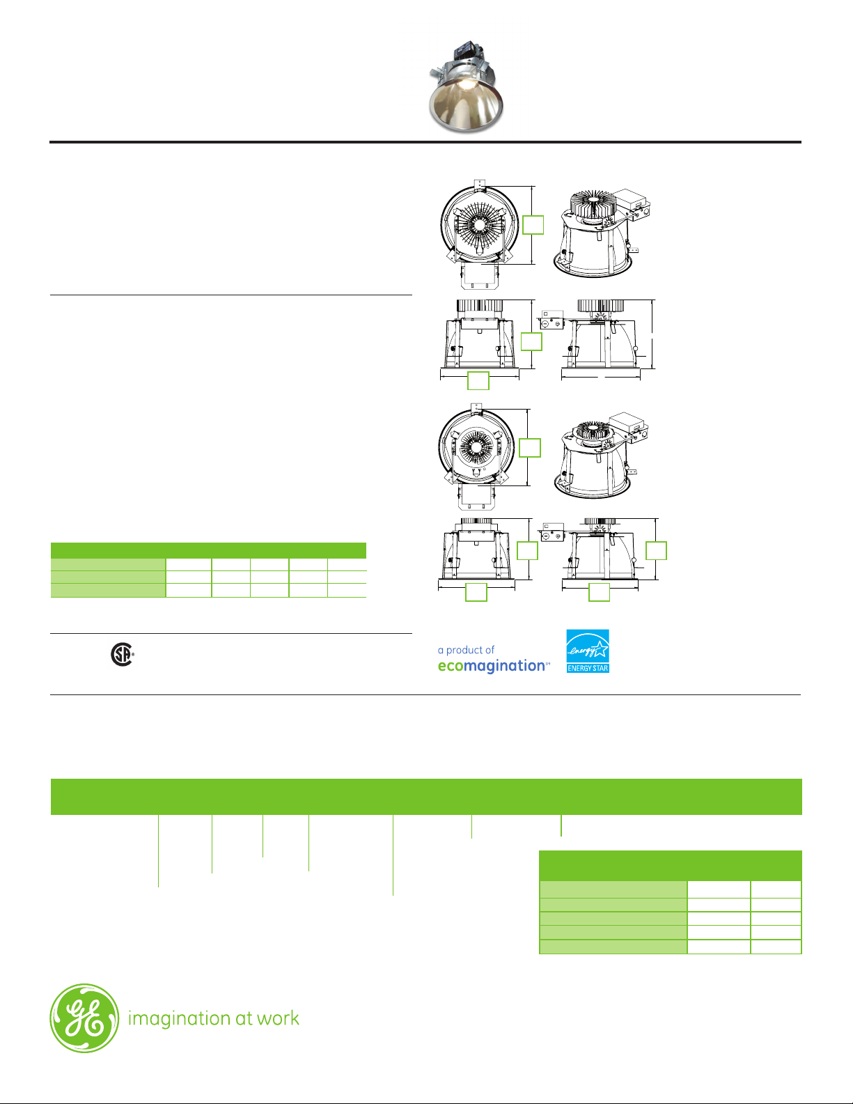
Product Dimensions: RI10
10.8
A
9.47
B
10.8
10.8
A
10.8
A
8.69
10.8
AA
High Lumen
(3000, 4000 lm)
A = 10.8 B = 9.47
BB
Low Lumen
(1000, 1500, 2000 lm)
A = 10.8 B = 8.69
Listings:
• Suitable for damp locations.
Ordering Information:
R I 1 0
_ _ _ _ _ _ _ _ _ _ _ _ _ _ _ _
HOUSING
RI10 = Retrofit Downlight,
Infusion, 10” Round
Ordering Notes:
1. Use with CW = White reflector color only.
2. Reflector colors (other than white paint) available with
RM = Semi-specular reflector finish only.
3. See back page of spec sheet for goof ring dimensional info.
4. 277V input , 1000 lumen version is not Energy Star certified.
MODULE LUMENS
10 = 1000 LM
15 = 1500 LM
20 = 2000 LM
30 = 3000 LM
40 = 4000 LM
For shortest lead time and lowest price, order standard reflector options shown in bold.
CCT
27 = 2700K
30 = 3000K
35 = 3500K
40 = 4000K
BEAM
SPREAD
N = Narrow
M = Medium
W = Wide
REFLECTOR
FINISH
RM = Semi-specular
RD = Diffused
RS = Specular
1
RP
= Painted
REFLECTOR
COLOR
CL = Clear
2
= Black
CB
2
= Gold
CK
2
= Pewter
CP
2
= Wheat
CT
CW = White Paint
FLANGE
FM = Match Reflector
FW = White
347V Field Installed Transformer Kit
10” Goof Ring, Specular Finish RIGR10RS
10” Goof Ring, Semi-Spec Finish RIGR10RM
10” Goof Ring, Diffused Finish RIGR10RD
10” Goof Ring, White Painted RIGR10WH
VOLTAGE
1 = 120V, 0-10V dimming
2 = 277V, 0-10V dimming
ACCESSORIES
4
4
DESCRIPTION
CODE
TR347/120-75VA
PRODUCT
CODE
83264
3
16168
3
16169
3
16175
3
16176
Page 2
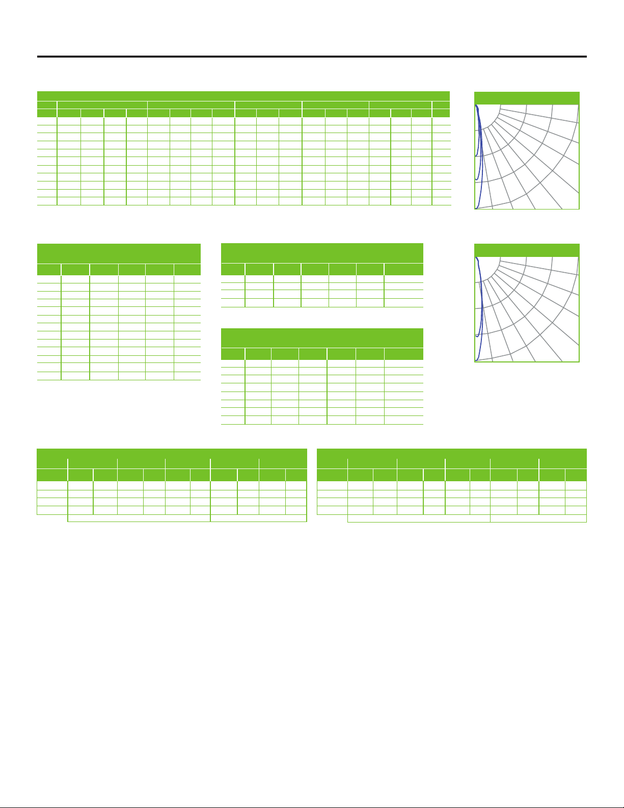
Photometric Data:
Lumination
TM
RI10 Series Downlights
Narrow Distribution
Performance claims are for clear specular reflectors. Other reflector finishes and colors will have an effect on performance.
RC 80% 70% 50% 30% 10% 0%
RW 70% 50% 30% 10% 70% 50% 30% 10% 50% 30% 10% 50% 30% 10% 50% 30% 10% 0%
0 119 119 119 119 116 116 116 116 111 111 111 106 106 106 102 102 102 100
1 115 112 110 109 112 110 108 107 106 105 104 103 102 101 99 98 98 96
2 110 107 103 101 108 105 102 100 102 99 97 99 97 95 96 95 93 92
3 106 101 97 94 105 100 96 94 98 95 92 95 93 91 93 91 89 88
4 103 97 92 89 101 96 92 89 94 90 88 92 89 87 90 88 86 84
5 99 93 88 85 98 92 88 84 90 86 84 89 85 83 87 84 82 81
6 96 89 84 81 94 88 84 81 87 83 80 86 82 80 84 81 79 78
7 93 85 81 78 91 85 81 77 84 80 77 83 79 77 82 79 76 75
8 90 82 78 75 89 82 78 75 81 77 74 80 77 74 79 76 74 73
9 87 80 75 72 86 79 75 72 78 74 72 78 74 71 77 74 71 70
10 84 77 73 70 83 77 72 69 76 72 69 75 72 69 75 71 69 68
NOTE: Floor Cavity Reflectance : 20%
COEFFICIENTS OF UTILIZATION
Narrow – 1000, 1500, 2000 Lm
2764
5528
8291
11055
10 20 30 40
POLAR GRAPH
90
80
70
60
50
CANDLEPOWER SUMMARY
NOMINAL MODULE LUMENS
1000 1500 2000 3000 4000
Angle Candela Candela Candela Candela Candela
0 5462 8067 10923 16445 21475
5 4340 6410 8680 13067 17064
10 2131 3147 4262 6416 8379
15 1116 1649 2233 3362 4390
20 516 762 1032 1554 2029
25 408 602 815 1227 1603
30 351 519 703 1058 1381
35 233 345 467 703 918
40 65 96 131 196 257
45 8 11 15 23 30
50 2 2 3 5 6
55 1 2 2 3 4
60 1 1 2 2 3
ZONAL LUMEN SUMMARY
NOMINAL MODULE LUMENS
1000 1500 2000 3000 4000
Zone Lumens Lumens Lumens Lumens Lumens % of Fixture
0 - 30° 749 1107 1499 2257 2948 85.2
0 - 40° 869 1283 1738 2616 3417 98.8
0 - 60° 879 1298 1758 2647 3457 99.9
0 - 90° 880 1299 1760 2649 3460 100
CONE OF LIGHT
NOMINAL MODULE LUMENS
1000 1500 2000 3000 4000
Height fc fc fc fc fc Dia. (ft.)
6’ 152 224 303 457 597 1.6
8’ 85 126 171 257 336 2.1
10’ 55 81 109 164 215 2.6
12’ 38 56 76 114 149 3.2
14’ 28 41 56 84 110 3.7
16’ 21 32 43 64 84 4.2
18’ 17 25 34 51 66 4.7
20’ 14 20 27 41 54 5.3
APPLICATION REFERENCE (Open Space)
NOMINAL MODULE LUMENS
1000 1500 2000 3000 4000
Spacing Avg. fc W/ft2 Avg. fc W/ft2 Avg. fc W/ft2 Avg. fc W/ft2 Avg. fc W/ft
4’ x 4’ 57.4 0.96 84.7 1.38 114.8 1.74 155.0 2.46 202.4 3.24
6’ x 6’ 26.8 0.45 39.5 0.64 53.6 0.81 72.3 1.15 94.5 1.51
8’ x 8’ 14.3 0.24 21.2 0.35 28.7 0.44 38.7 0.62 50.6 0.81
10’ x 10’ 9.6 0.16 14.1 0.23 19.1 0.29 25.8 0.41 33.7 0.54
LLF: 1.0 Initial, 80/50/20 Reflectances, 2.5’ workplane LLF: 1.0 Initial, 80/50/20 Reflectances, Light levels on the ground
10’ ceiling, Open Space: 50’ x 40’ x 10’ 10’ ceiling, Corridor: 6’ W x 100’ L20’ ceiling, Open Space: 50’ x 40’ x 20’ 20’ ceiling, Corridor: 6’ W x 100’ L
Narrow – 3000, 4000 Lm
POLAR GRAPH
5434
10867
16301
21734
10 20 30 40
APPLICATION REFERENCE (Corridor)
NOMINAL MODULE LUMENS
1000 1500 2000 3000 4000
2
Spacing Avg. fc W/ft2 Avg. fc W/ft2 Avg. fc W/ft2 Avg. fc W/ft2 Avg. fc W/ft
4’ on ctr. 29.5 0.67 43.6 0.96 59.1 1.21 69.5 1.71 90.8 2.25
6’ on ctr. 20.1 0.45 29.6 0.65 40.2 0.82 47.2 1.16 61.7 1.53
8’ on ctr. 14.2 0.32 20.9 0.46 28.3 0.58 33.4 0.82 43.6 1.08
10’ on ctr. 11.8 0.27 17.4 0.38 23.6 0.48 27.8 0.68 36.3 0.90
90
80
70
60
50
2
Spacing Criteria: RI10 - Narrow = 0.30
Page 3

Photometric Data:
Lumination
TM
RI10 Series Downlights
Medium Distribution
Performance claims are for clear specular reflectors. Other reflector finishes and colors will have an effect on performance.
RC 80% 70% 50% 30% 10% 0%
RW 70% 50% 30% 10% 70% 50% 30% 10% 50% 30% 10% 50% 30% 10% 50% 30% 10% 0%
0 119 119 119 119 116 116 116 116 111 111 111 106 106 106 102 102 102 100
1 114 112 110 108 112 110 108 106 106 104 103 102 101 100 99 98 97 95
2 110 105 102 99 107 104 100 98 100 98 96 98 95 94 95 93 92 90
3 105 100 95 92 103 98 94 91 96 92 90 93 91 88 91 89 87 86
4 101 94 90 86 99 93 89 85 91 87 84 89 86 84 87 85 83 81
5 97 90 85 81 95 89 84 81 87 83 80 85 82 79 84 81 79 77
6 93 85 80 77 92 85 80 76 83 79 76 82 78 75 81 77 75 74
7 89 81 76 73 88 81 76 72 79 75 72 78 75 72 77 74 71 70
8 86 78 73 69 85 77 72 69 76 72 69 75 71 68 74 71 68 67
9 82 74 69 66 81 74 69 66 73 69 65 72 68 65 71 68 65 64
10 79 71 66 63 79 71 66 63 70 66 63 69 65 62 69 65 62 61
NOTE: Floor Cavity Reflectance : 20%
COEFFICIENTS OF UTILIZATION
Medium – 1000, 1500, 2000 Lm
925
1851
2776
3701
10 20 30 40
POLAR GRAPH
90
80
70
60
50
CANDLEPOWER SUMMARY
NOMINAL MODULE LUMENS
1000 1500 2000 3000 4000
Angle Candela Candela Candela Candela Candela
0 1839 2716 3677 5536 7229
5 1649 2436 3299 4966 6486
10 1503 2221 3007 4527 5911
15 1440 2128 2881 4337 5664
20 973 1436 1945 2928 3824
25 527 778 1054 1587 2072
30 349 515 698 1051 1372
35 234 346 469 706 922
40 67 99 133 201 262
45 8 13 17 26 33
50 2 3 4 6 8
55 1 2 3 4 6
60 1 2 2 3 4
ZONAL LUMEN SUMMARY
NOMINAL MODULE LUMENS
1000 1500 2000 3000 4000
Zone Lumens Lumens Lumens Lumens Lumens % of Fixture
0 - 30° 748 1106 1497 2255 2944 85.1
0 - 40° 868 1282 1736 2613 3413 98.6
0 - 60° 878 1298 1757 2646 3455 99.9
0 - 90° 880 1299 1760 2649 3460 100
CONE OF LIGHT
NOMINAL MODULE LUMENS
1000 1500 2000 3000 4000
Height fc fc fc fc fc Dia. (ft.)
6’ 51 75 102 154 201 4.2
8’ 29 42 57 87 113 5.7
10’ 18 27 37 55 72 7.1
12’ 13 19 26 38 50 8.5
14’ 9 14 19 28 37 9.9
16’ 7 11 14 22 28 11.3
18’ 6 8 11 17 22 12.7
20’ 5 7 9 14 18 14.2
APPLICATION REFERENCE (Open Space)
NOMINAL MODULE LUMENS
1000 1500 2000 3000 4000
Spacing Avg. fc W/ft2 Avg. fc W/ft2 Avg. fc W/ft2 Avg. fc W/ft2 Avg. fc W/ft
4’ x 4’ 56.7 0.96 83.7 1.38 113.4 1.74 150.7 2.46 196.8 3.24
6’ x 6’ 26.5 0.45 39.1 0.64 52.9 0.81 70.3 1.15 91.8 1.51
8’ x 8’ 14.2 0.24 20.9 0.35 28.3 0.44 37.7 0.62 49.2 0.81
10’ x 10’ 9.4 0.16 13.9 0.23 18.9 0.29 25.1 0.41 32.8 0.54
LLF: 1.0 Initial, 80/50/20 Reflectances, 2.5’ workplane, Light levels on the ground LLF: 1.0 Initial, 80/50/20 Reflectances, 2.5’ workplane, Light levels on the ground
10’ ceiling, Open Space: 50’ x 40’ x 10’ 10’ ceiling, Corridor: 6’ W x 100’ L20’ ceiling, Open Space: 50’ x 40’ x 20’ 20’ ceiling, Corridor: 6’ W x 100’ L
Medium – 3000, 4000 Lm
POLAR GRAPH
1819
3638
5457
7276
10 20 30 40
APPLICATION REFERENCE (Corridor)
NOMINAL MODULE LUMENS
1000 1500 2000 3000 4000
2
Spacing Avg. fc W/ft2 Avg. fc W/ft2 Avg. fc W/ft2 Avg. fc W/ft2 Avg. fc W/ft
4’ on ctr. 27.5 0.67 40.6 0.96 55.0 1.21 59.2 1.71 77.4 2.25
6’ on ctr. 18.7 0.45 27.6 0.65 37.4 0.82 40.3 1.16 52.6 1.53
8’ on ctr. 13.2 0.32 19.5 0.46 26.4 0.58 28.4 0.82 37.1 1.08
10’ on ctr. 11.0 0.27 16.2 0.38 22.0 0.48 23.7 0.68 30.9 0.90
90
80
70
60
50
2
Spacing Criteria: RI10 - Medium = 0.70
Page 4

Photometric Data:
Lumination
TM
RI10 Series Downlights
Wide Distribution
Performance claims are for clear specular reflectors. Other reflector finishes and colors will have an effect on performance.
RC 80% 70% 50% 30% 10% 0%
RW 70% 50% 30% 10% 70% 50% 30% 10% 50% 30% 10% 50% 30% 10% 50% 30% 10% 0%
0 119 119 119 119 116 116 116 116 111 111 111 106 106 106 102 102 102 100
1 113 110 107 105 111 108 106 103 104 102 100 100 99 97 97 95 94 93
2 107 102 97 94 105 100 96 92 97 93 90 94 91 88 91 89 87 85
3 101 94 88 84 99 92 87 83 90 85 82 87 84 81 85 82 79 78
4 95 87 81 76 93 85 80 76 83 78 75 81 77 74 79 76 73 71
5 89 80 74 69 88 79 73 69 77 72 68 76 71 67 74 70 67 65
6 84 74 68 63 83 73 67 63 72 66 62 70 66 62 69 65 61 60
7 79 69 62 58 78 68 62 57 67 61 57 66 61 57 64 60 57 55
8 75 64 57 53 73 63 57 53 62 57 53 61 56 52 60 56 52 51
9 70 60 53 49 69 59 53 49 58 52 48 57 52 48 56 52 48 47
10 66 56 49 45 65 55 49 45 54 49 45 54 48 45 53 48 45 43
NOTE: Floor Cavity Reflectance : 20%
COEFFICIENTS OF UTILIZATION
Wide – 1000, 1500, 2000 Lm
338
676
1014
1352
10 20 30 40
POLAR GRAPH
90
80
70
60
50
CANDLEPOWER SUMMARY
NOMINAL MODULE LUMENS
1000 1500 2000 3000 4000
Angle Candela Candela Candela Candela Candela
0 456 673 912 1372 1792
5 453 670 907 1365 1782
10 511 755 1023 1539 2010
15 571 843 1142 1719 2244
20 593 876 1187 1786 2333
25 618 912 1235 1860 2429
30 644 951 1288 1939 2532
35 545 805 1090 1641 2143
40 283 419 567 853 1114
45 86 127 173 260 339
50 16 23 31 47 61
55 3 4 6 9 11
60 2 3 4 6 8
ZONAL LUMEN SUMMARY
NOMINAL MODULE LUMENS
1000 1500 2000 3000 4000
Zone Lumens Lumens Lumens Lumens Lumens % of Fixture
0 - 30° 496 733 993 1495 1953 56.4
0 - 40° 805 1189 1610 2424 3166 91.5
0 - 60° 877 1296 1755 2643 3451 99.8
0 - 90° 880 1299 1760 2649 3460 100
CONE OF LIGHT
NOMINAL MODULE LUMENS
1000 1500 2000 3000 4000
Height fc fc fc fc fc Dia. (ft.)
6’ 13 19 25 38 50 7.6
8’ 7 11 14 21 28 10.2
10’ 5 7 9 14 18 12.7
12’ 3 5 6 10 12 15.3
14’ 2 3 5 7 9 17.8
16’ 2 3 4 5 7 20.4
18’ 1 2 3 4 6 22.9
20’ 1 2 2 3 4 25.5
APPLICATION REFERENCE (Open Space)
NOMINAL MODULE LUMENS
1000 1500 2000 3000 4000
Spacing Avg. fc W/ft2 Avg. fc W/ft2 Avg. fc W/ft2 Avg. fc W/ft2 Avg. fc W/ft
4’ x 4’ 54.9 0.96 81.0 1.38 109.8 1.74 138.3 2.46 180.6 3.24
6’ x 6’ 25.6 0.45 37.8 0.64 51.2 0.81 64.5 1.15 84.3 1.51
8’ x 8’ 13.7 0.24 20.3 0.35 27.4 0.44 34.6 0.62 45.1 0.81
10’ x 10’ 9.1 0.16 13.5 0.23 18.3 0.29 23.0 0.41 30.1 0.54
LLF: 1.0 Initial, 80/50/20 Reflectances, 2.5’ workplane, Light levels on the ground LLF: 1.0 Initial, 80/50/20 Reflectances, 2.5’ workplane, Light levels on the ground
10’ ceiling, Open Space: 50’ x 40’ x 10’ 10’ ceiling, Corridor: 6’ W x 100’ L20’ ceiling, Open Space: 50’ x 40’ x 20’ 20’ ceiling, Corridor: 6’ W x 100’ L
Wide – 3000, 4000 Lm
POLAR GRAPH
664
1329
1993
2657
10 20 30 40
APPLICATION REFERENCE (Corridor)
NOMINAL MODULE LUMENS
1000 1500 2000 3000 4000
2
Spacing Avg. fc W/ft2 Avg. fc W/ft2 Avg. fc W/ft2 Avg. fc W/ft2 Avg. fc W/ft
4’ on ctr. 22.2 0.67 32.7 0.96 44.3 1.21 38.8 1.71 50.7 2.25
6’ on ctr. 15.1 0.45 22.3 0.65 30.1 0.82 26.4 1.16 34.4 1.53
8’ on ctr. 10.6 0.32 15.7 0.46 21.3 0.58 18.6 0.82 24.3 1.08
10’ on ctr. 8.9 0.27 13.1 0.38 17.7 0.48 15.5 0.68 20.3 0.90
90
80
70
60
50
2
Spacing Criteria: RI10 - Wide = 1.52
Page 5

• SPACING REQUIREMENTS FOR FIXTURE: EACH INDIVIDUAL FIXTURE NEEDS TO
HAVE 576 SQUARE INCHES OF SPACE BEFORE ANY OBJECT/OBSTRUCTION
• THERMAL PROTECTION FEATURE PRESENT IN MODULE THAT PROTECTS LEDS
FROM OVERHEATING IN ABNORMAL CONDITIONS
36 Inches
16 Inches
FRAME SIZE 10”
9.32” High Lumen
8.34” Low Lumen
PARAMETER
A Width of Frame with Swing Arm Extended 13.55”
B Height from Bottom of Reflector to Top of Heat Sink
C Height from Bottom of Reflector to Top of Frame 6.52”
D Reflector Diameter 10.80”
E Cut-Out Dimension for Ceiling
10.50” - 12.50” (w/Goof Ring)
F Maximum Ceiling and Rough-in Kit Thickness 4.25”
9.75” - 10.50”
Product Specifications:
Construction:
• 18 gauge galvanized steel housing
• 14 gauge aluminum reflectors resist dents during transportation and installation
• Custom engineered heat sinks for passive cooling at all lumen option
Installation:
• Universal mounting frame installs from below the ceiling and secures to existing
rough in kit with 3 mounting clamps
• Hinged J-box eases installation through ceiling hole and then flips into traditional
remodel housing position
• Included tether secures to existing fixture frame for hands-free wiring
www.gelighting.com
GE and the GE Monogram are trademarks of the General Electric Company. All other trademarks are the property
of their respective owners. Information provided is subject to change without notice. All values are design or typical
values when measured under laboratory conditions. GE Lighting and GE Lighting Solutions, LLC are businesses of
the General Electric Company. © 2014 GE.
IND093 (Rev 10/13/14)
Optical System:
• Custom engineered reflectors for precise beam distributions and 45° cutoff to light source
and source image
• Self-flanged design with white or reflector-matching flange
• Available in specular, semi-specular, and diffused finishes in 10 different colors to precisely
match exisitng fixtures
• Reflector is retained by four torsion springs to ensure uniform seating to LED module for
exceptional light distribution for the life of the product
Electrical System:
• Infusion DLM LED module for exceptional performance and tool-free upgradeability
• Standard 0-10V dimming, high efficiency drivers
• Pre-wired with 30” flexible armored cable and push-in connector compatible with 1/2” knockout
on existing junction box
• Thermal protection feature in module protects LEDs from overheating in abnormal conditions
For more information and access to all of our resources, including our
design tool visit: www.gelighting.com
 Loading...