

Page 1
GE
Lighting
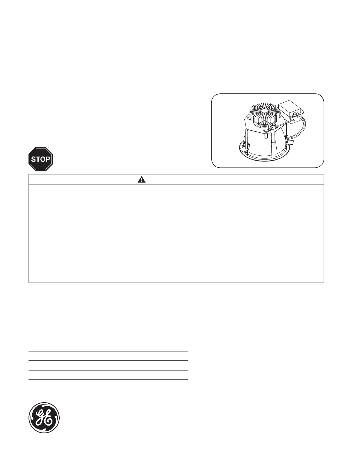
LuminationTM LED Luminaire
(RI Series)
BEFORE YOU BEGIN
Read these instructions completely and carefully.
WARNING/AVERTISSEMENT
RISK OF FIRE OR ELECTRIC SHOCK
• Turn power off before inspection, installation or removal.
• Properly ground electrical enclosure.
• Follow all NEC and local codes.
• Use only UL approved wire for input/output connections.
Minimum size 18 AWG or 14 AWG for continuous runs.
• Install this kit only in the luminaires that has the construction
features and dimensions shown in the photographs and/or drawings.
• Do not alter, relocate, or remove wiring, lampholders, power
supply, or another electrical component.
• Installation of this retrot assembly requires a person familiar with
the construction and operation of the luminaire’s electrical system
and the hazard involved. If not qualied, do not attempt
installation. Contact a qualied electrician.
• To prevent wiring damage or abrasion, do not expose wiring to
edges of sheet metal or other sharp objects.
RISQUES D’INCENDIE OU DE DÉCHARGES ÉLECTRIQUES
• Coupez l’alimentation avant d’’inspecter, installer ou déplacer le luminaire.
• Assurez-vous de correctement mettre à la terre le boîtier d’alimentation
électrique.
• Respectez tous les codes NEC et codes locaux.
• N’utilisez que des ls approuvés par UL pour les entrées/sorties de
connexion. Taille minimum 18 AWG ou 14 AWG pour les rangées continues.
• Risques d’incendie ou choc L’installation de trousses de mise à niveau au DEL
nécessite des connaissances des systèmes électriques d’éclairage.
• Risque d’incendie ou d’électrocution. N’ installer cette trousse que sur des
luminaires qui ont les caractéristiques de construction et les dimensions
telles que montrées sur les photographies et dessins présentés.
• Ne pas percer ou altérer les trous d’un boitier contenant l ou composant
électrique durant l’installation.
• Pour prévenir les dommages ou l’abrasion de ls électriques, ne pas exposer
les ls aux arêtes de pièce de tôlerie ou n’importe quels autres objets
tranchant.
Installation Guide
Save These Instructions
Use only in the manner intended by the manufacturer. If you have any questions, contact the manufacturer.
The retrot kit is accepted as a component of a luminaire where the suitability of the combination shall be
determined by CSA or authorities having jurisdiction.
Do not make or alter any open holes in an enclosure of wiring or electrical components during kit installation.
Through Wiring for 15A Circuit
Lumen Level Maximum number of xtures
1000, 1500, 2000 lumen 30
3000, 4000 lumen 20
imagination at work
Page 2
Prepare Electrical Wiring
Electrical Requirements
The LED driver must be supplied with 120-277 VAC,
50/60 Hz and connected to an individual properly
grounded branch circuit, protected by a 20 ampere
circuit breaker. Use min. 75°C supply conductor.
Grounding Instructions
The grounding and bonding of the overall system
shall be done in accordance with National Electric
Code (NEC) Article 600 and local codes.
Fixture Requirements
• Per the NEC, this xture is non-plenum rated for use in ducts specically fabricated for environmental air. It is suitable for use above
the ceiling in open spaces used for environmental air.
• 35°C maximum cavity temperature during lamp operation.
• Thermal protection feature present in module that protects LEDs from overheating in abnormal conditions.
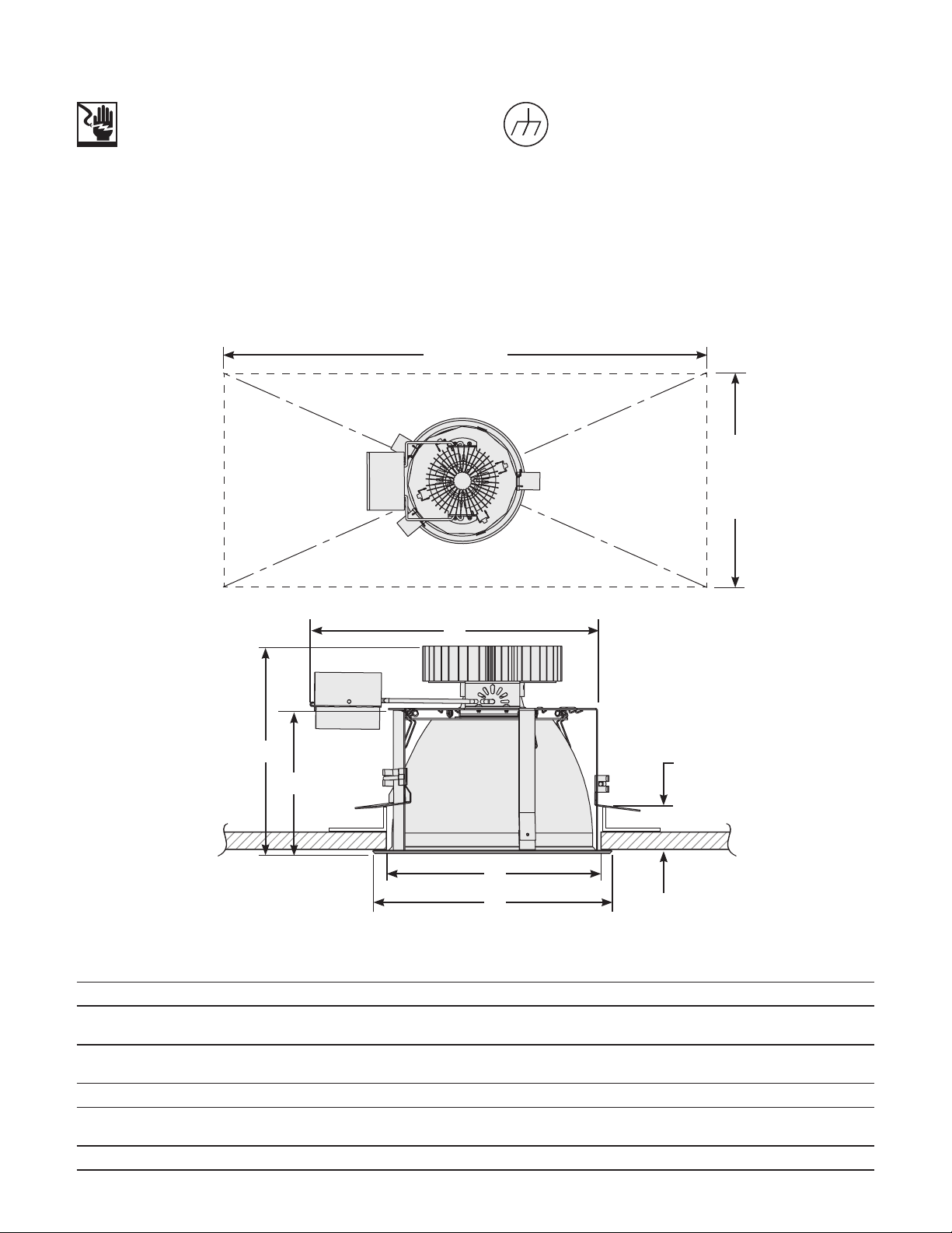
• Spacing requirements for xture: each individual xture needs to have 576 square inches of space before any object/obstruction.
36 inches
16 inches
A
B
F
C
E
D
Frame Size
Parameter 6” 8” 10”
A Width of Frame with Swing Arm Extended 10.34” 12.51” 13.55”
Height from Bottom of Reector to Top of
B
Heat Sink
Height from Bottom of Reector to Top of
C
Frame
D Reector Diameter 7.40” 8.80” 10.80”
E Cut-Out Dimension for Ceiling
F Maximum Ceiling and Rough-in Kit Thickness 1.625” 3.00” 4.25”
5.92” Low Lumen
3.91” 5.57” 6.52”
6.45” - 7.125”
7.125” - 7.88” (w/Goof Ring)
8.37” High Lumen
7.39” Low Lumen
7.88” - 8.50”
8.5” - 9.75” (w/Goof Ring)
9.32” High Lumen
8.34” Low Lumen
9.75” - 10.50”
10.50” - 12.50” (w/Goof Ring)
Page 3

Installation
Shut off power to the lighting system.
1
Remove
Remove existing lamp and reector.
2
Attach other end of the tether to
5
xture housing and let hang.
Ceiling
Tether
Disconnect wiring. Remove old
3
components, such as lamp sockets,
ballasts, etc. while retaining existing
rough-in kit components.
Connect ex cable from xture to
6
junction box.
Loop one end of the tether to existing
4
rough-in kit.
Connect the black, white and green
7
wires of the AC line to the black,
white and green wires of the xture
using twist-on wire connectors. Close
junction box.
NOTE: See wiring diagram below if
connecting an optional dimming line.
J-box is
vertical
Orient J-box vertically and slide
8 9
xture housing (without reector)
into existing rough-in kit. Then
rotate J-box horizontally.
Restore power to the lighting system.
11
Slide
L-brackets
over notches
Slide the L-brackets to the top of
each leg and ensure the bracket
slot channel is engaged by pushing
the bracket through the notches.
Slide each bracket down to engage
existing rough-in kit and tighten
thumb screws.
Snap in reector.
10
Page 4

Optional Installation: 0-10 Volt Dimming Lighting Controller
At output side of LED driver, make appropriate connections
using twist-on wire connectors. Follow lighting controller
installation instructions.
Line (black)
Neutral (white)
Ground (green)
(0-10V) + (violet)
(0-10V) - (gray)
0-10V wiring diagram
Line
Neutral
Ground
DRIVER
(0-10V) -
(0-10V) +
This device complies with Part 15 of the FCC Rules. Operation is subject to the following two conditions: (1) This device may not cause harmful interference,
and (2) this device must accept any interference received, including interference that may cause undesired operation. This Class [A] RFLD complies with the
Canadian standard ICES-003. Ce DEFR de la classe [ A ] est conforme á la NMB-003 du Canada.
Note: This equipment has been tested and found to comply with the limits for a Class A digital device, pursuant to part 15 of the FCC Rules. These limits are
designed to provide reasonable protection against harmful interference when the equipment is operated in a commercial environment. This equipment
generates, uses, and can radiate radio frequency energy and, if not installed and used in accordance with the instruction manual, may cause harmful
interference to radio communications. Operation of this equipment in a residential area is likely to cause harmful interference in which case the user will be
required to correct the interference at his own expense.
GE Lighting • 1-888-MY-GE-LED (1-888-69-43-533) • www.gelighting.com
GE Lighting Solutions, LLC is a subsidiary of the General Electric Company. The GE brand, logo, and Lumination are trademarks of the General Electric Company.
© 2015 GE Lighting Solutions, LLC. Information provided is subject to change without notice. All values are design or typical values when measured under laboratory conditions.
IND098-011315
 Loading...