

Page 1
How to get the best from
Your
Contents
~ ]
,
Aluminum Foil
Anti-Tip Device
Appliance Registration
Care and Cleaning
Clock
and Timer
Consumer Services
lmportmt
(lmverting to I.P or
Phone
Numbers
~~. 25, 30
2, 3, 35, 43
28–33
12, 13
51
51
Oven
Vents
Ro&sling,
~
Self-Cleatling
Shelves
Power
Problem Solver
Thermostat
lx)
Roasting
Outage
It
Yol(r.wlf
Adjustmm-
I
5,33
Guide 21, 22
~5_?7
Is,
16
13
49,
50
Z()
use
and
&Installation
of Models
RGB744
RGB745
care
Natural
Features
Installation Instructions
Air
Flooring Under
Leveling
Model and Serial Numbers 2
oven
Biking
Broiling, Broiling
Control
Door Removal
Light;
Oven
Gas
Adlustnlent
Se[tings
BLIlb
Replacement 14,
Botmn
Range
Guide
44.48
6,
34Lt3
42
36
43
14-27
1619
23, 24
31
32
30
Safety Instructions
7 Surface Cooking
Burners
Control Settings
Cooktop
Cookware
Flame Size
lighting Instructions
Warranty
II
GE Answer Center
800.626.2000
Comparison
Tips
3-5
8-I()
8- I ()
x, g
x
10
g
8
Back cover
(]
ttcnFolNr
Page 2
HELP US HELP YOU...
Read this guide carefully.
It is intended to help you operate and
Ilcw’ l“:in:L! pl”opc’l”ly.
Keep it hmdy for
If
yoLI d(m’(
wrik
(
inc]udc y(~LIr
CYollsumer
t+c~tpoint
Appli:lncc
l.(~uis~illc,
tinswcrs [o
Llndcrstancl something or
phone
Affdirs
Park
KY
40225
your questions.
numb”):
Write down the model and serial numbers.
Depending
scri:il llulllbCI”S
behind
‘“1’hcsc
Ownership
r:Inge. Fkforc
Ilumbcl’s here:
Model Number
on your
the
kick
IIUlllbC1’S :II”C :1[S() 011 (hC
Rcgis(ration Cd
sending in this
on
panel,
rmge, you’ll
ii
Iilhel
011
s[(mge drawer
the front of the
~ollSLltllCl”
(hot
cm{, pleaw wrik
Serial Number
m~lint:lin
need
find
the mode! dnd
or
c:unc
your
more
range.
hroikr
drdwer.
[>rOLiLld
with yoLIr
these
help,
WARNING: If
the information in this
guide is not followed exactly, a fire or
explosion may result causing property
damage, personal injury or death.
— Do not store or use gasoline or other
flammable vapors and liquids in the
vicinity of this or any other appliance.
— WHAT TO DO IF YOU SMELL GAS
●
Do not try to light any appliance.
●
Do not touch any electrical switch; do
not use any phone in your building.
●
Immediately call your gas supplier from
a neighbor’s phone. Follow the gas
supplier’s instructions.
●
If you cannot reach your gas supplier,
call the fire department.
USC Ihcsc numbcls
cdl
Is
Collccrll
It’
you received a damaged range . . .
lmndi~l(ely
you
tllc
r:ulge.
in
any CI)I”J-CS}30tlCiCllCC
i
ng
Y(JLI1° I“:U1:C
c(mt:ict the dcder
(or builder)
Save time and money. Before you
request service . .
ChCC!i ~he
1(
]iStS
call
——
Problcm
CLILISCS of lllill(M” Opcra(in:
Col”rcc( youl”scl f.
Solver in the
back 01’
pr(~h]enls thu(
●
IN.IURY TO
COIJLD
●
INSTALL
this
PERSONS
RESULT
ANTI-TIP
DEVICES PACKED
WITH RANGE
●
SEE
1NSTALLATION
lNSTRUCTIONS
1
/)
Ah!)
b.-
2’
or
scrvicc
th:l( sold
guide.
J’OLI
— Installation and service must be
performed by a qualified installer, service
or
the
gas
agency
supplier.
IF YOU NEED SERVICE
To obtain service,
(he back
To
Service Centers.
We’re
pleased. If for some
service
further help.
FIRST, contact the
appliance. Explain why you are not
cases,
NEXT,
details—including your phone number-to:
FINALLY, it’ your problem is still
of this
obtain
replacement parts,
proud
you
receive, here are three steps to
this will solve the problem.
if
you
Manager, Consumer Relations
Hotpoint
Appliance Park
Louisville, KY 40225
Major Appliance Consumer Action
z() Nor[h Wacker
Chicago, IL.
scc
the Consumer
guide.
of our service
reason
people
are
still
not
pleased, write all
Drive
60606”
Services piigc
contact CiE/Hotpoint
and
want you to
you
arc
not happy with
who
serkicd
your
pletised.
not
resolved, write:
Panel
he
follow
for
I n most
the
in
[he
‘*”
@).4pPR0uED
0
Page 3

IMPORTANT SAFETY NOTICE
●
The
California Safe Drinking Water and Toxic
Enforcement Act
to publish a list of substances known to the state
to cause cancer, birth defects or other reproductive
harm, and requires businesses to warn customers
of potential exposure to such substances.
Gas appliances can cause minor exposure to
four of these substances,
monoxide, formaldehyde and soot, caused primarily
by the incomplete combustion of natural gas or
LP
fuels. Properly adjusted burners, indicated by a
bluish rather than a yellow flame, will minimize
incomplete combustion. Exposure to these
substances can be minimized by venting with an
open window or using a ventilation fan or hood.
●
Fluorescent light
standing pilot ranges contain mercury.
model has these features, they must be recycled
according to local, state and federal codes.
When You Get Your Range
●
Have the installer show you the location of the
range gas cut-off valve and how to shut it off
if necessary.
●
Have your range installed and properly
grounded by a qualified installer,
with the Installation Instructions. Any adjustment
and service should be performed only by qualified
gas range installers or service technicians.
●
Do not attempt to repair or replace any part of
your range unless it is specifically recommended
in this guide.
to a qualified technician.
●
Plug your range into a 120-volt grounded
outlet only.
prong from the plug. If in doubt about the grounding
of the home electrical system, it is your personal
responsibility and obligation to have an ungrounded
outlet replaced with a properly grounded,
prong outlet in accordance with the National
Electrical Code. In Canada, the appliance must be
electrically grounded in accordance with the
Canadian Electrical Code. Do not use an extension
cord with this appliance.
●
Locate the range out of kitchen
and out of drafty locations to prevent pilot
outage (on standing pilot models) and poor
air circulation.
requires the Governor of California
namely benzene, carbon
bulbs
and safety valves on
If your
in accordance
AH other servicing should be referred
Do not remove the round grounding
three-
traff]c
path
●
Be sure all packing materials are removed from
the range
before operating it to prevent fire or
smoke damage should the packing material ignite.
●
Be sure your range is correctly adjusted by a
qualified service technician or installer for the
type of gas (natural or LP) that is to be used.
Your range can be converted for use with either
type of gas. See the Installation Instructions.
WARNING: These adjustments must be made by
qualified service technician in accordance with the
manufacturer’s instructions and all codes
znd
requirements of the authority having jurisdiction.
Failure to follow these instructions could result in
serious injury or property damage. The qualified
agency performing this work assumes responsibility
for the conversion.
●
After prolonged use of a range, high floor
temperatures may result and many floor
will
coverings
not withstand this kind of use.
Never install the range over vinyl tile or linoleum
that cannot withstand such type of use. Never
install it directly over interior kitchen carpeting.
Using Your Range
A
VVM?RJING-AII
can tip and injury could result. To
prevent accidental tipping of the
range,
attach it to the wall and
installing the Anti-Tip device supplied.
To check if the device is installed and
engaged properly, carefully tip the
range forward. The Anti-Tip device should engage
and prevent the range from tipping over.
pull
If you
the range out from the wall for any
reason, make sure the device is properly engaged
when you push the range back against the wall.
If it is not, there is a possible risk of the range
tipping over and causing injury if you or
stand, sit or lean on an open door.
Please refer to the Anti-Tip device information
in this guide. Failure to take this precaution could
result in tipping of the range and injury.
●
Do not leave children alone or unattended
where a range is hot or in operation.
They could be seriously burned.
●
For your safety, never use your appliance for
warming or heating the room.
ranges
floor
by
@
(&)
a
child
,4
i.
a
3
Page 4

IMPORTANT SAFETY INSTRUCTIONS
(continued)
“
CAUTION: ITEMS OF INTEREST TO
CHILDREN SHOULD NOT BE STORED IN
CABINETS ABOVE A RANGE OR ON THE
BACKSPLASH OF A RANGE—CHILDREN
CLIMBING ON THE RANGE TO REACH
ITEMS COULD BE SERIOUSLY INJURED.
●
Do not allow anyone to climb, stand or hang
on the door, broiler drawer or cooktop. They
could damage the range and even tip it over,
causing severe personal injury.
●
Let the burner grates and other surfaces cool
before touching them or leaving them where
children can reach them.
●
Never wear loose fitting or hanging garments
while using the appliance.
Be careful when
reaching for items stored in cabinets over the
cooktop. Flammable material could be ignited if
brought in contact with flame or hot oven surfaces
and may cause severe burns.
●
Do not use water on grease fires. Never pick up
a flaming pan.
Turn the controls off. Smother a
flaming pan on a surface unit by covering the
pan completely with a well-fitting lid, cookie sheet
tlat
tray. Use a multi-purpose dry chemical or
or
foam-type fire extinguisher.
Flaming grease outside a pan can be put out by
covering it with baking soda or, if available, by
using a multi-purpose dry chemical or foam-type
fire extinguisher.
Flame in the oven can be smothered completely by
closing the oven door and turning the oven off or
by using a
tnulti-purpose
dry chemical or
foam-
type fire extinguisher.
●
Do not store flammable materials in an oven, a
range broiler or storage drawer or near a cooktop.
●
DO NOT STORE OR USE COMBUSTIBLE
MATERIALS, GASOLINE OR OTHER
FLAMMABLE VAPORS AND LIQUIDS IN
THE VICINITY OF THIS OR ANY OTHER
APPLIANCE.
●
Do
not let cooking grease or other flammable
materials accumulate in or near the range.
●
When cooking pork,
follow the directions exactly
and always cook the meat to an internal temperature
of at least
17(PF.
This assures that, in the remote
possibility that trichina may be present in the meat,
it will be killed and the meat will be safe to eat.
Surface Cooking
●
Always heat fat slowly, and watch as it heats.
4
s
Always use the LITE position (on electric
ignition models) or the HI position (on standing
pilot models) when igniting the top burners
and
make sure the burners have ignited.
●
Never leave the surface burners unattended at
high flame settings.
Boilovers
cause smoking
and greasy spillovers that may catch on fire.
●
Adjust the top burner flame size so it does not
extend beyond the edge of the cookware.
Excessive
●
Use only dry pot holders—moist
tlame
is hazardous.
or damp pot holders
on hot surfaces may result in burns from steam.
●
Do not let pot holders come near open flames
when lifting cookware.
Do not use a towel or other
bulky cloth in place of a pot holder.
●
To minimize the possibility of burns,
ignition
of flammable materials and spillage, turn cookware
handles toward the side or back of the range
without extending over adjacent burners.
●
Always turn the surface burners to
of”f bef’ore
removing cookware.
●
Carefully watch foods being fried at a
high
flame setting.
●
Never block the vents (air openings) of the
range.
They provide the air inlet and
outlet
that
are necessary for the range to operate properly
with correct combustion. Air openings are located
at the rear of the cooktop, at the top and bottom
ot
the oven door, and at the bottom of the range under
the broiler drawer.
●
Do not use a wok on models with sealed burners
if the wok has a round metal ring that is placed
over the burner grate to support the wok.
This
ring acts as a heat trap, which may damage the
burner grate and burner head. Also, it may cause
the burner to work improperly. This may cause a
carbon monoxide level above that allowed by
current standards, resulting in a health hazard.
●
Foods for frying should be as dry as possible.
on frozen foods or moisture on fresh foods can
Frost
ctiuse
hot fat to bubble up and over the sides of the pan.
●
Use the least possible amount of fat for effective
shallow or deep-fat frying.
of
fat
can cause spillovers when food is added.
●
Use a deep fat thermometer
Filling the pan
too full
whenever possible to
prevent overheating fat beyond the smoking point.
●
Never try to move a pan of hot fat,
deep fat fryer. Wait until the
o
When using glass cookware,
fat
make sure it is
especially a
is cool.
designed for top-of-range cooking.
Page 5
●
If a combination of oils or fats will be used
in frying,
stir together before heating or as fats
melt slowly.
●
Use
proper pan
size—Avoid pans that are
unstable or easily tipped. Select cookware having
flat bottoms large enough to properly contain food
and avoid
boilovers
and spillovers and large
enough to cover burner grate, This will both save
cleaning time and prevent hazardous accumulations
of food, since heavy spattering or spillovers left
on range can ignite. Use pans with handles that
can be easily grasped and remain cool.
●
Keep all plastics away from the top burners.
●
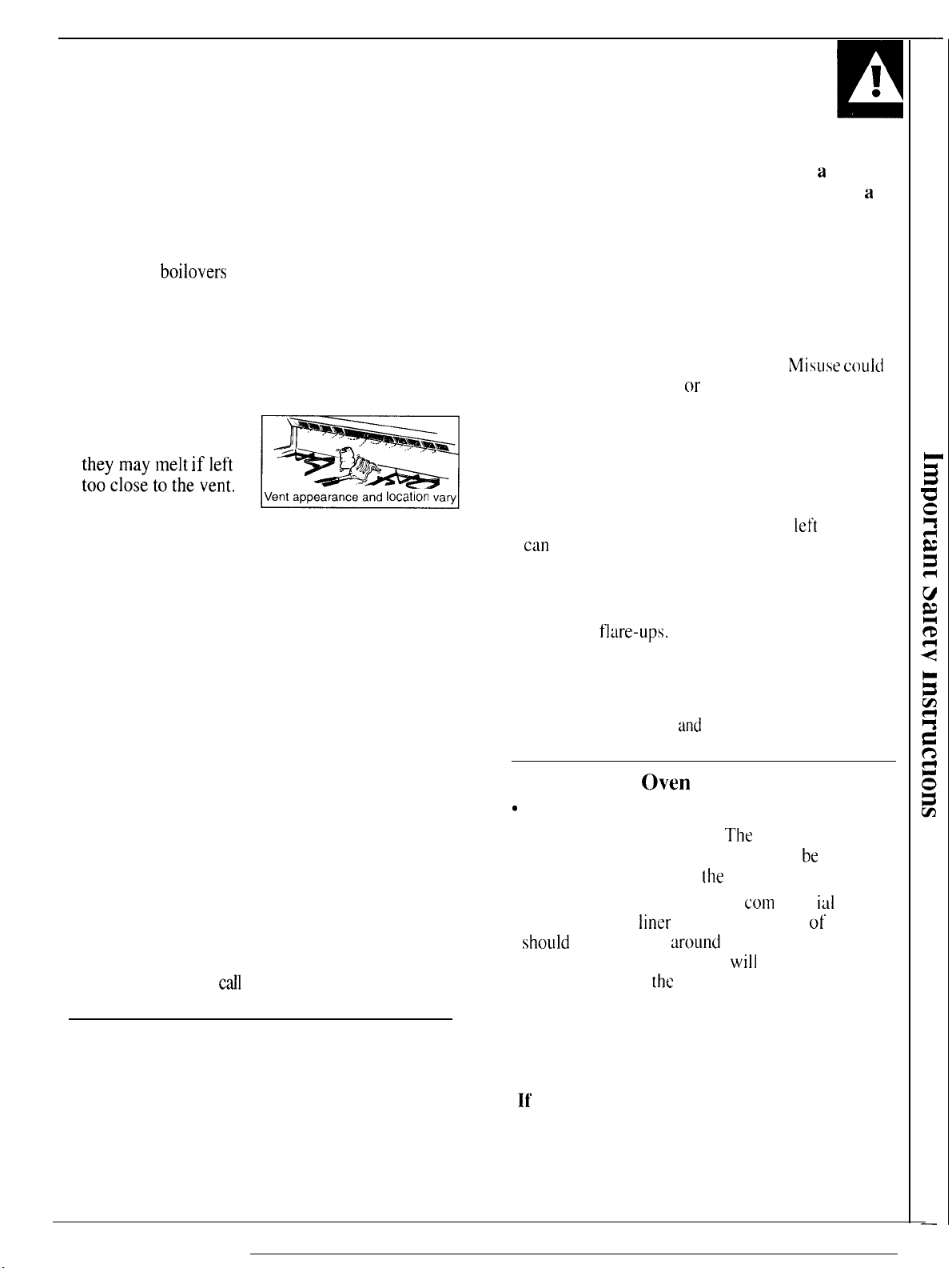
Do not leave plastic
items on the cooktop-
they may melt If left
‘OOclOsetOthevent m
●
Do not leave any items
Vent appearance and
Iocatlon
vary
on the cooktop.
The hot air from the vent may ignite flammable
items and will increase pressure in closed
containers, which may cause them to burst.
●
To avoid the possibility of a burn, always be
certain that the controls for all burners are at
the off position and all grates are cool before
attempting to remove them.
●
When flaming foods are under the hood, turn
the fan off. The fan, if operating, may spread
the flames.
●
If range is located near a window,
do not hang
long curtains that could blow over the top burners
and create a fire hazard.
●
When a pilot goes out
(on standing pilot models),
you will detect a faint odor of gas as your signal
to relight the pilot. When relighting the pilot,
make sure burner controls are in the off position,
and follow instructions in this book to relight.
●
If you smell gas,
and you have already made sure
pilots are lit (on standing pilot models), turn off the
gas to the range and
call
a qualified service technician.
Never use an open flame to locate a leak.
Baking, Broiling and Roasting
●
Do not use the oven for a storage area.
Items stored in the oven can ignite.
●
Place the oven shelves in the desired position
while the oven is cool.
●
Stand away from the range when opening the
door of a hot oven.
escapes can cause burns to hands, face and eyes.
The hot air and steam that
i
●
r!
●
Keep the oven free from grease buildup.
●
Pulling out the shelf to the shelf-stop is
convenience in lifting heavy foods. It is also
precaution against burns from touching hot
surfaces of the door or oven walls. The lowest
position “R” is not designed to slide.
●
Do not heat unopened food containers. Pressure
could build up and the container could burst,
causing an injury.
●
Do not use aluminum foil anywhere in the oven
except as described in this guide.
result in a fire hazard m- damage to the range.
●
When using cooking or roasting bags in the
follow the manufacturer’s directions.
oven,
●
Use only glass
cookware that is recommended
for use in gas ovens.
●
Always remove the broiler pan from range as
soon as you finish broiling.
con
catch fire if oven is used without removing
Grease
the grease from the broiler pan.
●
When broiling, if meat is too close to the flame,
the fat may ignite.
excessive
●
Make sure the broiler pan is in place correctly
tlare-ups.
Trim excess fat to prevent
to reduce the possibility of grease fires.
●
If you should have a grease fire in the broiler pan,
turn off oven control,
and
keep broiler drawer and
oven door closed to contain fire until it burns out.
Self-Cleaning
Q
Clean only parts listed in this Use and
●
Do not clean door gasket.
(lven
The
door gasket is
essential for a good seal. Care should
[he
to rub, damage or move
●
Do not use oven cleaners. No
cleaner or oven
shou]d
be used in or
liner
protective coating of any kind
w-ouncl
Residue from oven cleaners
the
of the oven when
●
Before self-cleaning the oven, remove broiler
self-clean cycle is used.
gasket.
com
any part of the oven.
will
damage the inside
pan and rack and other cookware.
●
Be sure to wipe up excess spillage before
starting the self-cleaning operation.
●
If
the self-cleaning mode malfunctions, turn
the oven off and disconnect the power supply.
Have it serviced by a qualified Technician.
SAVE THESE
INSTRUCTIONS
a
Misww could
left
in the pan
Care Guide,
be
taken not
mere id oven
a
5
Page 6

FEATu~s
OF YOUR RANGE
f
!
II
6
I
Features and
,/”
‘ ‘----’>
,—
(’
— -.
-.,, .-.
/
/
/ i
T.... (
1[’
1
Your range is equipped with one of the two types of surface burners shown above.
&
,.
,
L_.,,,,,”
‘
.-J
(on some
‘y,, ~~~~~~~ase
‘ 2.\
(
[-~>~B”rner
$:~j;,
appearance
)
\,
m
Page 7
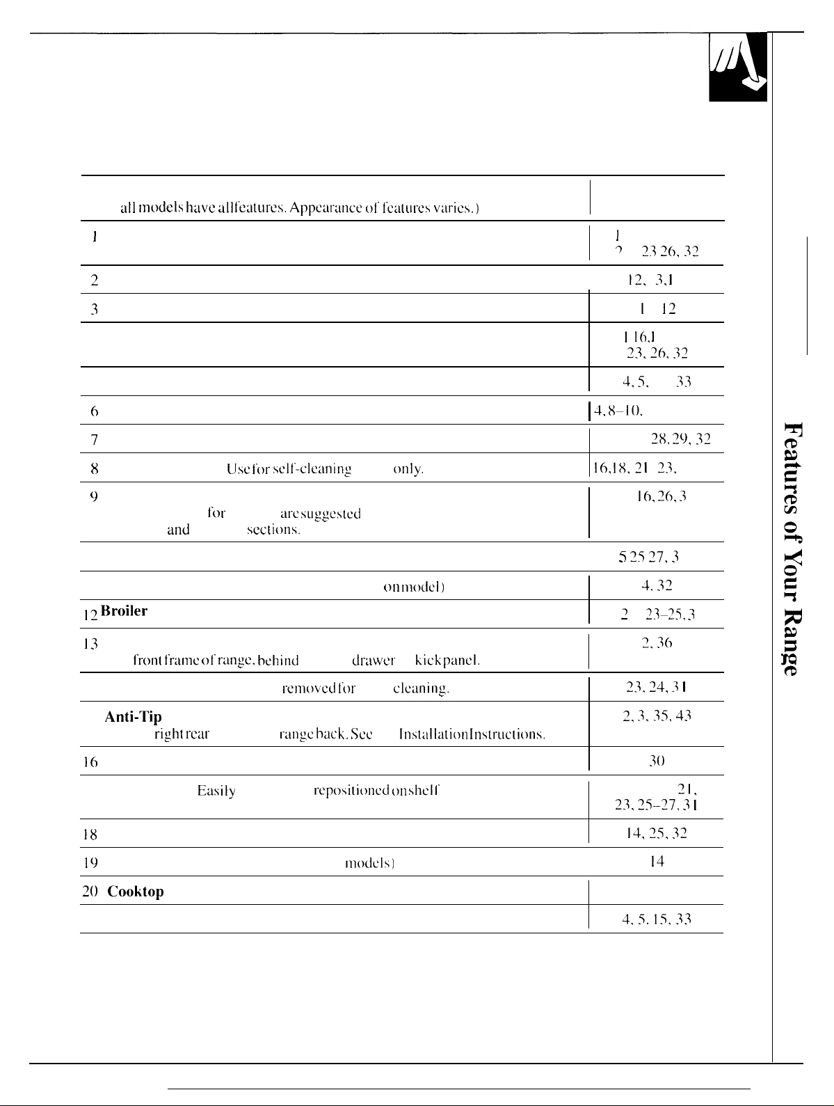
Feature Index
(Not
all models have all
I
OVEN SET Knob
2
Clock and Minute Timer
3
OVEN CYCLE Light
4 OVEN TEMP Knob
5 Oven Vent
6
Grates, Drip Pans (on some models) and Surface Burners
feLItLIres.
Appcw:mce 01” I’C:NUI-CS vmics.)
Explained
on page
I
1, 16.18, 19,
~
I 33
12,
I(3, I
I 3,
I
1,
~6, 32
I
12
X-2 I .
- , -. . -
I
I I ,
~~, ~(,, :{?
4, 5.
Is.
I 4.
8-I(). 25,28-30
x
33
7
Surface Burner Control Knobs
8
Oven Door Latch
9
Oven Shelf Supports
Shelf’ positions
Roasting
10 Oven Door Gasket
11 Storage Drawer or Kick Panel (depending
12
~roiler pan and Rack
13
Model and Serial Numbers
On
I 4 Lift-off Oven Door Easily
15
Anti-1’ip
Lower
16
Removable Oven Bottom
17 Oven Shelves
18
Oven Interior Light
and
f’ron( frame of” range, behind
Device
righ[ I-car
(Jsc for sell’-cleanin:
i“or
cooking wc
Broiling
Easily
sections.
corner on
removed or
cycle
slrgges[cd
storage
r“enlovccf f’t)r
range hack. Scc
reposi[i~)nd on shell’
in the Baking.
dr-:iwcr
oven
only.
(~n
rn(del)
or
kick panel.
c]cdning.
the Instdla[ion tnstrudions.
supports.
4, 8.9,
16,
18.2 I ,
Is,
T ~’i 77, 3
-
, -. . -
I
5, 2 I ,
~j.
2,
3.35,
5. 14–18.
~J, ~5–?7, J I
14, 25, 32
28,
29.32
23,
25–27
I(3, 26, 3
4. 32!
23–25, 3
2, 36
~q, j I
30
I
I
I
43
21,
19
Oven Light On/Ofmf Switch (on some
20 Cooktop
Air Vents
in(xlcls)
I
14
30.33
4.5. 15, 33
7
Page 8

Your
11(2W
cook(op” has
to cooking wi(h
Llnils. yoLl
gas
burrlcl”s.
‘I~pC
(;as
~+
Wi] i llo(icc SOI1lC
of’
Cooktop”
Burners
,.0,
Radiant
(Glass (’manic)
C()()kt()p
o
Solid Disk
--
\
\
[-.)
HOW DOES THIS COOKTOP COMPARE
TO YOUR OLD ONE?
gas
indLlction or
di
Description
[<t~llkll” 01” SCa]LXt
gas burners
c ilhcr I
01” natul”al
I
li:h I’rcqucncy
i
miuct
~lndcr:1
slil’kl!.
F’la(lcnd
1
L[bi n: contain
c
IcL’( ric
w’ ire
SLl>pClldL’d
()~cr a drip pan.
Solid
i
I i SL scaled
l’m)k(op
burllcl-s.
other electric
ft’crcnces
.1)
ion coi
glass
resistance
cast
(ISC
gas
gas.
Is
Inclal
i
Ilg
iron
[()
the
Sul”t’acc.
It’
yoU
tit-c
USed
surface
when yoLl Llse
The best types
of
cookware to use, plus heat-Lip and
coot-down times, depend upon the type
sLlrface unit you have.
The following chart will help you to understand the
differences be{ween gas
other type
of’
cooktop yOLI may
burner
cooktops and
have
used in the past,
How it Works
I:l:uncs heti[
pans should
heat sc((ings
Iicat
(he bottom
cx)ntinue cooking
you
Pans tnusl be made of’ Icrrx)us
pr(duccd by a magnetic circuit between the coil and the pan. Heats up right away
and changes heat settings
01’1’, the gl~iss cxx)k[op
Heats
cook ing l“c?suits, LISC
warped pans than radiant or solid disks.
heat sct(ings
Lx)n[inuc
Heats by direct contact
cooking”
Liisk skrys
I’IX)II) {hc
the
pans directly. Pan
be
well balanced.
right away.
[ravc]s
to
[hc giass suri’x?c and then
(or
good
w’an(
cooking to stop.
by direct contact with the
as quickly as
cooking for a short time after (hey m
results.
hot enough to continue cooking alter it is
solid disk it’ you
When you turn the control
cooking results, The glass
after it is turned oft.
metals
right
is
hoI [’mm
good qud ity pans. ~]ectric coils are more forgiving
gas
wi(h
Hca(s
up and cools down more slowly than electric coils. The
wunt (1w
I’lattwss
GLIS
burners
to
Rcmove (he pan
(metal
awuy, 1
ikc a
the
heal of’
pan
and by heating the air
or induction. Electric coils stay hot
(he
pan, so
pans
cooking to stop.
is not critical to cooking results, but
heat
the pan right away and
off,
cooking stops right away.
the
cookware, so pans must be flat on
Lxmktop
that attracts a magnet). Heat is
gos
the pan,
Heats
up quickly but does not change
must be flat on the bottom for good
stays
hol
from [he surface unit if”
cooktop.
turned
A1’ter
hut
cooking stops right
under
off.
lurnuf
off. Remove the pan
enough to
turning the control
the pan. For best
of:
burner or
any
change
of
enough to
away.
I.ighting Instructions
Your
surt’acc
e]
im ina[ ing the need
constant Iy burn i 0:
[n case
burncl”s on
match
position. [Jse
burners
of” a
power-
your t“an.gc
I\J
the burner, then turn the knob to
are lighted
for
standing pi
1’1 aINcs.
failure,
with a match. }qold a
extreme caution when lighting
burners this way.
Suri’acc burners in
t’ailurc
(lccur-s
usc
whco an
will
con[inuc 10 opcr-a(c normally.
8
SURFACE COOKING
by electric ignition,
Io(
I ights
with
yt~u c;]n
light the surl’acc
L21cctrical
lighted
(IIC
LITE
power
The electrode ot’ the spark igniter is exposed.
When one burner is turned to LITE, all the burners
spark.
Do
not attempt to disassemble or clean
around any burner
An
electric shock may result, which could cause
you
to knock over hot cookware.
while
another burner is on.
Page 9

Surface Burner Controls
The
knobs tha(
located on the
The two
let-t rear
the right front
bLIrncrs.
control
knobs
and right
turn the
on
The two knobs
surface
panel
[he left
rear
in
control
on the right control
burners,
burners on
front
of the burners.
the left front
and
off are
and
ranges
On
●
The smaller burner (right
the best simmer results. [t
performance
foods
long time.
simmer setting.
●
The right i’rent burner is higher powered than the
others and will bring liquids to a boil quicker
(natural gas installations only).
with sealed burners:
rear
position) wi II give
offers
precise cooking
I’or
delicate
which need to
It cm be turned down to u very low
cook
foods.
such as sauces
over
low
heat
for a
or
Before Lighting a Burner
●
[ 1’
drip pans
they should be used tit al I
● M akc
bel’orc using
arc supplied
sure
al I grates on the rungc
any burner.
with
times.
After Lighting a Burner
●
Af’ter the hurncr ignites,
flame size.
●
Check to be
yoLl
Want to
sure
USC.
turn the knob to
the burner you
How to Select Flame Size
To Light a Surface Burner
you[”
range, Push the control knob in
LITE.
ittle
hand, a pot holder. cleaning
w-c
i n pldce
a(ijust
the ● Do not operate a burner
turned on is the one
and turn it to
will hear a I
noise-the sound
spark igniting the burner.
time
withou[ cookww-e
grate may chip without cookware to absorb
● Be sure the burners
place
y(JLIr
other materials on them.
YOLI
“cl icking”
ot’
the electric
on the
and grates
+
P
for
an
extended period ot”
grtite.
are
coo] bei’orc
1111
j
The
finisb
on the
the heat.
you
cloths
or
Watch the I’lame.
The [’lame
cookware
FOR
LET THE FLAME EXTEND
THE COOKWARE.
Any
wasted
size on a
yoLI are Llsi ng.
SAFE HANDLING OF COOKWARE NEVER
I“lame larger [hat] {he
and only serves to heat
not the knob,
burner
gas
bottom
as
y(JLI redLu heat.
shouid tnawh the
~JP
THE
S[DES
of’ the cm~kwarc
the
handle.
(jF
is
(Cil){litiflc{l II(.II p(i,qc)
9
Page 10
Top-of-Range Cookware
SURFACE COOKING
(continued)
Aluminum: Medium-weight cookware is
recommended because it heats quickly and evenly.
Most
foods
brown evenly in an
Use
saucepans with tight-fitting lids when cooking
with minimum
amounts
of
alulminum
water.
skillet.
Cast-iron: If heated slowly, most skillets will give
sa(isl’ac[ory l“CSUit
I+;namelware: Under
some cookware
IIl:itllll’;lctllt-ei”’s recotnlllendzltions” for
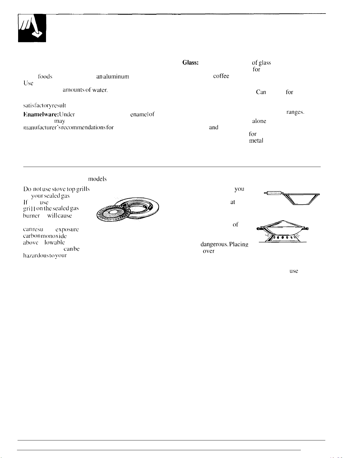
Stove Top Grills (on
[]() Ilot
LISe StOVC [Op gl”i]]S
on
ytmr sealed
11’
you
LISe
the stove top
gri ] I 011 the SeUILXI gLIS
burner
it
will
S.
some conditions. the
may
melt. Follow cookware
models
with sealed burners)
gw burners.
CilLISC
enamel ot’
cooking methods.
incomplete combustion and
can l“CiLl
carbon
above
standards. This
hUdl-dollS
It in
Cxposllre
nlonox” icic levels
to
al lowablc current
can be
to
~OUI”
health.
Glass:
There are two types of
for
oven use only and those for top-of--range cooking
(saucepans,
coffee
and teapots). Glass conducts heat
glass
cookware—those
very slowly.
Heatproof Glass Ceramic:
Can
be used
t’or
either
surface or oven cooking. It conducts heat very slowly
and cools very slowly. Check cookware manufacturer’s
directions to be sure it can be used on gas
Stainless Steel: This metal
properties
and
is usually combined with copper.
aluminum or other metals
distribution. Combination
alone
has poor heating
for
improved heat
[metal
skillets usually work
rmlges.
satisfactorily if they are used with medium heat as the
manufacturer recommends.
Wok Cooking (on models with sealed burners)
We recommend that
use only a flat-bottomed wok.
They are available at your local
retail store.
Do not use woks that have
support
rings.
types of woks, with or
without the ring in place,
can be
the ring
dan.zerous. Placing
ov~r
the burner g-rate may cause the burner
to work improperly resulting in carbon monoxide
levels above allowable current standards. This could
be dangerous to your health. Do not try to
woks without the ring. You could be seriously burned
if the wok tipped over.
yOLI
Use of these
w
usc
such
m
Page 11

FEATURES OF YOUR OVEN CONTROLS
OVEN SET
The OVEN
BAKE.
When
the proper
BAKE-UW
opcr~ltions-tor exwnplc.
cwscroles. Only
during
BROII,-Use
(broil ) burner will operate.
TIME BAKE—UW this setting to turn
and oil’ :it
st:ll”t :lIILI slop.
CLEAN-USC
I’utlction
Oven section.
BROIL,
yc)LI tLlt”n
burner is
baking.
specified times when you want cooking
only.
Control Knob
SET
control
TIME BAKE
the
knt~b to the
acliv:itccl for
this
sc[ting for
[he bottom oven
this setting
his sc[ting for the
See
the
Oper~l[ing
knoh Ims
all normal oven
for
for
settings
Jlld
CLEAN.
desired setting.
that operation.
cooking masts or
burner operates
broiling. Only the top
the
oven on
sell-cleaning
the Self-Cleaning
t’or
OVEN TEMP Control Knob
The OVEN TEMP control maintains the
temperature you
m WC I I m
temperature or [o
OFF—Shuts
will not operate.
turned to
For normal oven operation, push in
knob
30-90” WXX)IldS
After the oven reaches the selected temperature,
[he oven burner
21 t“Llli f]:lnlC-tO
The
the burner.
OFF whenever the
to the desired
OVEN CYCI.E light will
sel for
normal
for broi
I i
ng.
Push i n
set to lhc
off’ power to the
The
OVEN TEMP knob
temperature. It will normally take
before
the
cycles—off completely, then on with
kee
p the oven temperature controlled.
oven
operation
and
turn to
CLEAN position.
oven controls. The oven
oven
is not in USC.
flame
comes [)n
cycle on :md ofl’
and
set
should be
turn the
the
with
OVEN SET
T
(1
v
@
to
I
11
Page 12
FEATURES OF YOUR OVEN CONTROLS,
CLOCK AND TIMER
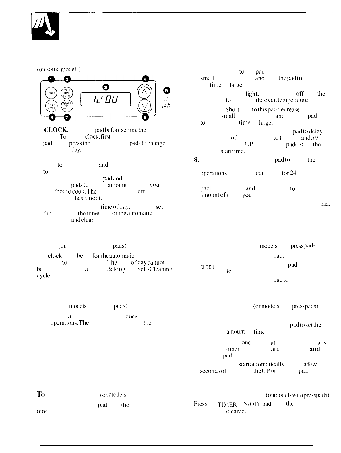
Clock and Timer with Press Pads
(on some m(xlels)
(38
HMt
R
(ON [,,6
1.
CLOCK.
clock. To set the
pad.
Then
the time of’
2. COOK TIME ON/OFF. Turn the OVEN SET
knob
to
the desired cooking temperature. Press the
COOK TIME ON/OFF
or DOWN
food
your
Cook Time
3. DISPLAY. Shows the
t’or
the timer,
operations
~+,
SIAII1
TIM(
,,,
,,,,
Press this pxl
press the
day.
to
TIME BAKE
pxls to set the
to
cook. The
has
the tilnes
:md clean
.—
—
before setting [he
clock. I“irst
UP or DOWN
rLIn oLII.
press the CLOCK
p~~ds to chtinge
and
the OVEN TEMP knob
pxl
und
then press the UP
mount
oven will shut off after
time
set
cycle.
ot’ time
of
ckiy,
the times
i’or the automutic
@
o
(1
yOLI
set
oven
:
OVkN
CYC1 t
want
4.
UP.
Short taps to this
smtill
amounts. Press
the
~ime
by
tal”gcr
5.
OVEN CYCLE
burner(s) to maintain
6. DOWN.
time by
to
decrease the
7. START TIME ON/OFF. Press this
the starting of your oven up to 1 I hours
minutes. Use the
desired
8.
TIMER ON/OFF. Press this
timer feature. The timer does not control oven
oper~tions.
To set the timer, first press the TIMER ON/OFF
pad.
mount
To
cancel the timer,
Short
taps to
small
amounts. Press
start time.
The timer
Press the UP
of 1 i me
pud
increase the time by
and
hold
the
amounts.
light.
Cycles on and
the oven temperi~ture.
[his p:ld decrease
and
hold the
time
by
Iargcr
amounts.
[JP
and DOWN
pad to
can
be set
and
DOWN pads to set the
yOLI
want.
press the TIMER ON/OFF
for 24
pxl to increase
oft’
with
the
pad to clclay
:md 59
pwls to
set
select
hours.
the
pad
the
the
pud.
Clock
The
functions
be
cycle.
Timer
The timer is a minute timer only: it
oven
is 24 hours.
TO
Press the UP or DOWN pxl until
time
(on
models with press
clock
must bc set
to
work properly.
changed during a Timed
(on
models
opcrdtions. The
Reset the Timer
is set.
I’or the automdtic
with press
maximum setting on
(w1
pads)
The
time of
Buking
ptids)
mOdCIS
oven timing
day cannot
or a
Self’-Cleaning
dtws
not control
[he
timer
with press pads)
the
desired
TO Set the Clock (on
1. Press the CLOCK
~LoCK
2. Press the UP or DOWN
to
o
set the time ot’ day.
3. Press the CLOCK
To Set the Timer
1. Press the TIMER ON/OFF pad.
TIMER 2. Press the UP or DOWN
ON/OFF
mount
ot’
modeIs
(on
mode]s
time
on the timer.
pad.
pad to
o
To set the timer
To set the
hold
the
pad.
The timer will
seconds
of releasing
To Cancel the Timer
press
the T[MER (] N/oFF
remaining is
one
minute at a time, tap the pxls.
timer
ten minutes at a time press
sturt uutornatically
[hc LJP or
(otl
pad
until
cleared.
with
ptid
start.
with
pxl to
within a
DOWN
IINMS
the
press
pxis)
press
pXIS)
set the
few
pad.
with press
time
and
PXIS)
12
Page 13

Powt!r outage
(on models with press
pads)
End of Cycle Tones
(on
mode]s
with press
pads)
When
power is restored, you will need to reset
The end of cycle tone is a series of three beeps.
the clock. Reminder beeps continue until the oven is turned off.
All other functions that were in operation when the
power went out will have to be programmed again.
Clock and Minute Timer with Dials
To set the clock, push the knob
in and turn the clock hands to
the correct time. Then let the
knob out and continue turning
to OFF.
\
12 ,
\ =.<’’”O %“’>,, 0
9
:10
-~
‘.,
20 40
0 ~,,,,
,,,, ,,\\\’
/\
(on some models)
:3
:
?“ \
b
60
on
the
Minutes are marked up to
center
ring of the clock.
To
set the
wirhu[ pushing in,
minute timer,
until the pointer reaches the number
turn the knob to the
left,
of minutes you want to time.
At the end of the set time, a buzzer sounds to tell
you time is up. Turn the knob,
without
pushin,q it?,
until the pointer reaches OFF and the buzzer stops.
The minute timer
has been combined with the range
clock. Use it to time cooking operations. You’ll
recognize it as the pointer that is different in color
from the clock hands.
Automatic Oven Timers with Dials
(on some models)
These timers will STOPTIME DELAY START
automatically start and
stop
your oven for you.
Here’s what you do:
~..,~’’:$’,,,,,
:9
~.
---
,..
3-:
..-.,
,,
,/, ,, ,,
\\.’
? -
PUSH TO TURN
\\.\ ’’’112” Z,
:, G;
,,
,/, ,, :,,\\.’
7
1. Make sure both your range clock and the DELAY
START dial show the correct time of day. When
either the DELAY START dial or STOP TIME dial
is pushed in and turned, it will “pop” into place
when the time shown on the range clock is reached.
2. Set the DELAY START dial. Push in and turn the
DELAY START dial to the time you want the oven
to turn itself on. (If you want it to start cooking
immediately, do not set DELAY START time. )
3. Set the STOP TIME dial. Push in and turn the
STOP TIME dial to the time you want the oven to
turn itself off.
NOTE:
There must be at least a half-hour difference
between the DELAY START and STOP TIME dials,
and times can be set only up to 11 hours
and
45
minutes in advance.
4. Set the OVEN SET knob to TIME BAKE (or
CLEAN).
5. Set the OVEN TEMP knob
10
the desired cooking
temperature (or CLEAN).
The oven will turn itself on immediately unless you
have set the DELAY START dial for a later starting
time. It will operate at the temperature you selected
and turn itself off at the Stop Time you selected.
Turn the OVEN TEMP knob to OFF and then take
your food out of the oven.
13
Page 14
USING YOUR OVEN
Before Using Your Oven
Bc
sure you understand how to set the controls
properly.
while the oven is
on
yoLI
using your new range.
Electric Ignition
V.1-
......— 1-... . . . . . ..—
I
ue
electric ignition.
To light either burner, turn
the
knob to
igni[e
After the
oven burner cycles—off’ completely, then on with a
full tlanle-to Iicep
Pructice
the t’ol
lowing
can
rel’cr (o
WeII uurmr WIU uruu uurnw
removin:
coo].
puges.
and
Read
the
Keep this
it, especially during the
J
L.-.. !1 t-....-. . . –—-
the
desired
oven
oper:ltion and [he
the
desired temperature. The burner should
within
S()-9()
seconds.
oven
reaches the selected
the oven temperature controlled.
replacing the shelves
information
guide
and
tips
handy where
first weeks of”
1? —[.
&..
J
are
IIgnLeu uy
L..
OVEN SET knob to
OVEN TEMP
temperature,
[he
Power Outage
CAUTION: DO
the electric ignition
power
fdilure.
The oven or broiler
f“;lilure. G~s
If’ the
oven
the
oven
burrwr
power is restored.
no[
will not flow
is in use
shuts
nuke any
LI[(cmp(
to
opcrutc
oven during an elcc[rical
cannot be
when a
lit
clur-ing a
unless the
power
off’
and cannot be
glow
t’aiiure
power
bar
occurs,
re-]it
is hot.
Llntil
Oven
Use
Light
the
switch on the control panel to turn the oven light on or
Oven Moisture
As your oven heats Lip, the temperature change OF the
air in
dle oven
door
glass.
evaporate as the oven continues to heat Lip.
may
c:wse
These droplets
water droplets to
are
harmless and will
f’orm
on
oil’.
the
14
Page 15
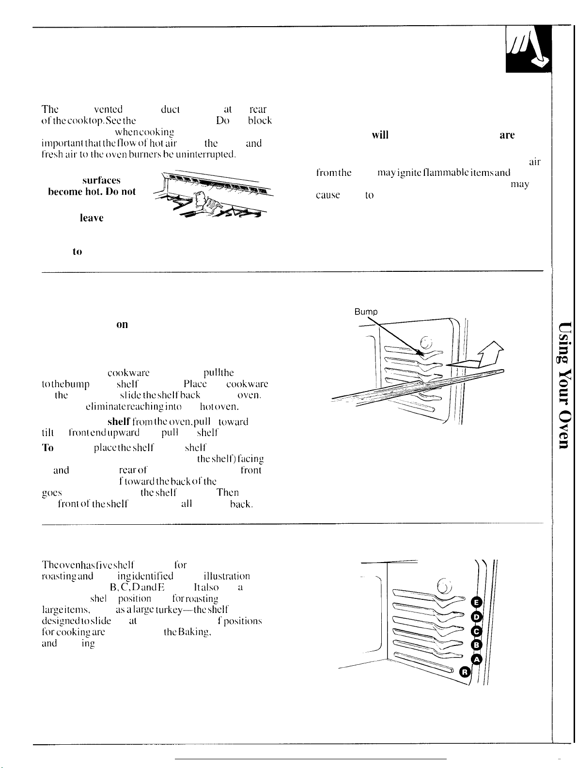
Oven Vents
The
oven is
of’ the cooktop. See the
these
impot-ltint th:lt [he l-low’
vented
openings
through
duc[
openings
Features section. Do not
when cooking
of
in the oven-it is
hot iiir
from
the
tit
the
oven
retu
block
and
fresh uil- tt) the oven burncl”s be Llllilltel’rll}lteci.
● The vent openings and
nearby
become,l(,~~{,not
touch them.
● Do not
items on the cooktop-
surf’aces
le~ve
plastic
may
j~=
9*=
Vent appearance and location vary
they may melt if left too
close
to
the vent.
Oven Shelves
The shelves are designed with stop-locks so when
placed correctly on the shelf’ supports, they will
stop before coming completely out of the oven and
will not tilt when you are removing food from them
or placing food on them.
When placing
to the bLInlp on the
on
the
shell’, then SI
This will
To remove a
tilt the
I’1”011( end
To
replace,
the stop-lochs (curved extension of
up
ond
toward the
and push the shel t’
goes
post the bump on
the
front of’ the
cookware
shelf
on a shell’.
support.
idc the shell’ tmck
climin~lte reaching in(o
shelf’ frotn the oven,
upww”d
plucc the shelf
and
pLl]l
on the
rear
of the oven. Tilt up the
toward the buck
the shell’
shelf and push it
pLIll
Pl~cc
the
into the
the
hot ~)ven.
pLIli
it
the
shelf
shclt’
support with
the shelf) t’acing
of
the
oven until it
support.
all
Then
the way
the shelf out
cookware
oven.
towtird
you,
out.
front
lower
back.
● Handles of pots and pans on the cooktop may
become hot if left too close to the vent.
● Metal items
will
become very hot if they
are
left
on the cooktop and could cause burns.
● Do not leave any items on the cooktop. The hot
from the
increase pressure in closed containers, which
cause
vent
may ignite Ilammablc items and
them to burst.
13umD
will
nmy
.
air
Shelf Positions
The oval Ims l’ivc shclt’
r(wting
as A (bottom). B, C, D
special low
lw”ge itcms,
designed to s] icie
for cooking ure
and
Broil
and
broil
she]
such m a
suggested in
in,g
sections.
i[lg identi I’ied
1’
position
out at this position. Shel 1“
supports
and E
(top). It
( R )
large
tul”key-the
the B:lking,
I’m
t-inking.
in this
illustr~ltion
also
for roasting
shelf
has
a
extra
is not
positions
Roasting
15
Page 16

BAKING
[f ycm
Do
not lock the oven door with the latch during
baking. The latch is used for self-cleaning only.
Your oven temperature is controlled very accurately
using an oven control system. It is recommended that
you operate the oven for a number of weeks to
become familiar with your new oven’s performance.
How to Set Your Range for Baking
To avoid possible burns, place the shelves in the 2. Check the food for doneness at the minimum time
correct position before you turn the oven on. on the recipe. Cook longer if necessary.
1. Close the oven door. Turn the OVEN SET knob to 3. Turn the OVEN TEMP knob to OFF and
BAKE
desired temperature.
tind
then turn the OVEN TEMP knob to the
Oven Shelves
think an adjustment is necessary, see the Adjust
the Oven
Yourself
Thermostat section. It gives easy
instructions on how to adjust the thermostat.
then remove the food.
Do It
Arrange
shelf or shelves in
the
locations while
the oven is
The correct shelf
position depends
on the kind of
food
browning desired.
As a
Dlacc”most foocfs
either shelf position B or C. See the chart for
stlggcsteci
the
desired
and
the
general rule,
shelf positions.
oven
coo].
in
the
middle of the oven. on
Preheating
Preheat the oven if the recipe calls for it. Preheat
means bringing the oven up to the specified
[temperature before putting the food in the oven.
To preheat, set the oven at the correct
selecting a higher temperature does not shorten
preheat time.
Preheating is necessary for good results when baking
cakes, cookies, pastry
and
r(ms(s,
preheating is not necessary. For ovens
without a
minutes. After the oven is preheated
in the oven as
f’rom
prehetit
q(lickly as
escaping.
and
breads. For most casseroles
indicator light or tone, preheat
possible to prevent heat
temperature-
place
the food
1()
Type
of Food
Angel
food cake
Biscuits or muffins
Cookies or cupcakes
Brownies
I
Layer cakes
I
Bundtor~ound cakes I A orB
I
Pies or pie shells
Frozen pies
Casseroles
I
Roasting
Shelf Position
A
B or C
B or C
B or C
B or C
I I
I
B or C
A (on cookie sheet)
B or C
]
B orR
Pan Placement
For even cooking and proper browning, there must be
enough room for air circulation in the oven. Baking
results will be better if baking pans are centered as
much as possible rather than being placed to the front
or to the back of the oven.
Pans should not touch each other or the walls of the
oven.
Allow
1 – to 1 ‘/~–inch space between pans as
well as from the back of the oven, the door and the
sides. If
so one is not directly above the other.
yoLl
need to use two shelves, stagger the pans
I
I
I
16
Page 17

Baking Guides
When
instructi(ms f’or best
using
prepared
baking results.
baking
Cookies
When
b~~king
cookies,
flat cookie
(without sides)
produce
cookies. Cookies
baked
pan
around
darker edges
or light browning may occur.
DO not Llse
wtil
Is or the door of
For best results,
at a (i
sheets
bet[ct--looking
in a
.jclly
(short sides
)
m:iy h:lvc
and pale
a
cookie
me.
roll
id]
LISC
sheet so
the
oven.
only one
Pies
mixes,
large that
cookie
f(Jllow
package recipe
it touches the
sheet in the oven
or
Aluminum Foil
Never
entirely cover
~1
shelf’ with duminun]
foil.
This will disturb
the heat circulation and
result in poor baking. A
slmaller
may be used to
spil]over
on a lower shelf’ several
inches
sheet of
by placing
below the
f“oi
catch
Cakes
I
il
food.
f
I
a
\
I
For best
to
produce a browner, crisper crust.
p~ms should be placed
for
from
resLIlls, bi~ke
baking since the shiny foil pan reflects
the
pie
crust; the
pies in dark, rough or dull
on an
uluminum cookie
cookie
sheet helps
Baking Pans
Use [he
the pan Lfetermincs
will
●
● Shiny, bright and smooth
“ CJl:iss baki tlg dishes :tlso absorb heal.
proper
OCCLI1”.
Dark. rol]gll
browner, crisper
in a lighter,
cookies require this type of pan.
in
glass buking
be l“dUd
bilking pun.
the amount of browning
or
dLIl 1
crust.
more de] icatc
dishes,
by 25( ’F.
The
pans absorb
Use this type
p~ms
browning.
the [emperaturc may
[ype
heut
reflect hwt,
Frozen
pies in
sheet A cake
heat
away
rettiin
it.
of finish on
thut
resu
Iti ng
in
for
pies.
rcsulti ng
Cakes
and
When bilking
need
pans
foil
u
to
When baking cakes,
uneven baking results and poorly shaped products.
b;lked
in a pan larger
recommends
than it
recommended. it may be undercooked and
overflow. Check the recipe to
used is the
will
should be. If btiked
onc
warped
usLIally
recommended.
be crisper, thinner
in a pan smaller
or bent pans will
than
the
recipe
th:m
baltcr may
m~~ke
sure
the pan
ctiuse
:md
drier
size
Don’t Peek
Set the
not open the door to look at your
provide minimum
as
DO NOT open the
time. Opening the oven door
cooking
longer.
timer for
“bake 30-40 minutes.”
allows
YoLIr
the estimated cooking time
and muximum
door to
heat to
baking
escape and
results
food. Mwst
baking
check until
I’rcyuen[ly
nukes baking times
may tilso be tifl’ectcd.
times
the
minimum
during
and do
recipes
such
17
—
Page 18

a
/“
For models with DELAY START and STOP TIME dials, see the
Automatic Oven Timers section in Oven Controls, Clock and Timer.
Automatic Oven Timer (on models with press pads)
TIMED BAKING
How to Time Bake
Do not lock the oven door with the latch during
regular timed baking. The latch is used for
cleaning only.
Your oven
NOTE: Before beginning, make sure the oven
shows the correct time of day.
can
be set to turn on
and of’f
automatically.
self-
CLOCK
o
clock
How to Set Immediate Start and Automatic Stop
To avoid possible burns, place the shelves in the
correct position before you turn the oven on.
The
oven will turn on immediately and cook
selected length of time. At the end
oven will
@@
1. Turn the OVEN SET knob to TIME BAKE.
2. Turn the OVEN TEMP knob to the desired
turn off automatically.
OVEN SET
temperature.
3.
COOK
TIME
ON/OFF
Press the COOK TIME ON/OFF pad.
OVEN TEMP
fq~-1~
of’
Cook Time the
t’or
a
S. The oven will
Cook Time remaining.
au[omatical Iy.
6.
When the
control
signal.
7. Remove the
foods
after the controls
NOTE: Foods that
fish, stuffings,
to sit for
Room temperature promotes
bacteria.
from the
o
Set the desired amount of cooking time
using the UP and DOWN pads.
To set the clock,
CLOCK pad. Press the UP or DOWN pad
until correct
the
CLOCK
tLIrn on.
set temperature, a
continue to cook
time up to I 1
oven
will
that
are left
nl& ihan O;C Imir- bcfor-c or after
Be
sure that oven light is off
bulb
for the
hours and
automatically turns
signal. Turn
Iood from
in the oven continue
arc oft.
spoil cxsiiy
poultry
will speed
first
press the
time
of
ciay
is displayed, Press
pad again to start.
The
display will show the
When ~he ~Jven
tone
sounds. The
programmed amount
50 minutes,
the
‘oven off to stop
the oven. Remember,
such
and pork
harmf’ul
should
the
growth of
bacteria growth,
reaches
oven
will
[hen shu[
off,
the oven
its
milk,
not be allowed
because heat
off
the
cooking”
eggs,
cooking.
harn]ful
the
ot’
18
Page 19

How to Set Delay Start and Automatic Stop
Quick Reminder
1. Turn the OVEN SET knob to TIME BAKE.
2.
Turn [he
desired
3. Press the
4.
Press the
desired length of cooking
5.
Press the
6.
Press the UP or DOWN
time
To avoid possible burns, place the shelves in the
correc{
position
You
c:m
automatically,
turn
off
For example:
shortly after
time
at
OVEN SET
@@
1. Turn
2.
TuI”n the
temperature (in this
COOK
TIME
ONIOFF
o
OVEN
tcmperiiturc.
COOK TIME ON/OFF pad.
UP or DOWN
START TIME ON/OFF pacf.
of
day
set
the oven
cook for a
lmtomatica]ly.
Let’s
7:()(). The
325°F.
Here’s how:
the
OVEN SET knob to TIME BAKE.
OVEN TEMP knob to the desired
3.
Press the
TEMP
knob to the
p~d to
set the
lime.
pad
to set the
yoLI
ww?t c(wking to
bef’orc
you
progrum
control to turn the oven on
specific length of time and
say it’s
COOK TIME ON/OFF
2:()()
recipe
OVEN TEMP
ivv339
exmnple 325[’F).
the
and dinner time is
suggests 3
start.
oven.
hours
baking
pfid.
4. For 3 hours
press the UP pad until
appears in the display.
@
of’
cooking time.
“3:()()”
5. Press the START TIME ON/OFF
START
TIME
n
w
6. Press the UP
display. The
2 hours,
Once the oven begins cooking, the Cook
remaining will be displayed.
At the
end
the oven will automatically turn oil’.
7. When the oven automatically turns
control
to OFF to stop the signal.
the oven. Remember, even
oft’
automatically,
controls
NOTE:
● The low temperature zone of
150”F and
f’oods
warm. Food kept in the oven
hours at these low temperatures may
●
Foods that spoi I
stuffings, poultry
to sit out for more than
cooking. Room temperature promotes the
of
harmful bacteria. Be sure the oven I
because heat from the bulb will
bacteria growth.
pad unlil “4:()()”
t;rner
is now set
at 4:()().
of’
the 3
hour cooking time
wil
I signal. Turn the OVEN TEMP knob
foods
tire
off.
2000 F)” is
tivailable
easi Iy
such as m i I k,
and
pork
appears in
to”start baking
RCITK)YC
though the oven
continue
this rwlgc
to
should
one
hour
speed hwmll’ul
oN.
the
cxx)king :tt’tcr the
p hot cooked
kcc
longer [him two
eggs,
not he
before
the
in
Time
(7:()()).
the
()\Jcn
food from
shuts
(between
spoil.
fish,
ill
lowed
or
~lftcr
yowth
ight
is oil’
pad.
Questions and Answers
~.
Can
I use the minute timer during oven
cooking?
A.
The
minute
cook in:
(imcr can
function.
he
Llseci
ciuring
my
Q.
Can I change the time of’ day on the
I’m Time Baking in the oven?
A. The time of
changed during
timer. You must either stop those programs or
until they
day
tire
finished
on the
clock
any
program
bel’ore ch:mging the [
should
thut
LIses the
nt)[ be
clock
(JVCI1
i me.
while
w:li[
19
Page 20

ADJUST THE OVEN THERMOSTAT—
DO IT YOURSELF!
You may feel that your new oven cooks differently
than the one it replaced.
LISC
your new oven
for o few
We
recommend that you
weeks to become more
fimiliar with it, following the times given in your
recipes
us
a guide.
If you think your new oven is too hot or too cold,
you can adjust the thermostat yourself.
it is too hot.
Ii’
you think it is too
make
it hotter.
We
do not recommend the use of inexpensive
thermometers, such
[o
check the temperature setting of your new oven.
These thermometers may vary
adjust [he
thermostat to make it cooler,
cool, acijust
:1s (hose found
the
in grocery stores.
2040” degrees.
OVEN TEMP
OFF
~v+
03
+
‘&e
@
Front of the OVEN TEMP knob
(1
Osv
T
v
#’
w
E
It’
yOLI
lhermmstat
think
to
Ad.iust
-
To
the Thermostat:
Note the position of the pointer to the screw
before making the adjustment.
Cooler Hotter
(appearance may vary)
Pull the OVEN TEMP knob off the range and look
at the back side.
To make adjustment. loosen (approximately
but
do
not completely remove, the two screws on the
back
of’
the knt~b.
you,
hold
the outer
und
turn the front of the knob with
To raise the oven temperature, move the top
towmd the right. You’ II
you move the knob.
screw
the top
the oven temperature approximately
plus or minus
We
suggest
from the original
betorc making
After the adjustment is
screws so they are
overtighten.
and check
pertorm:mce.
With
the btick of”
edge ot’ the
the knob
knob with one
the other
toward
the left.
600F
from the arrow. )
that
you
make
se[ting and check
hew-:1 click
To
lower
the adjustment onc
for
the
temperature, move
Each c1 ick
oven performance
my additional adjustments.
nmde, retighten
snug,
but be careful not to
Re-i
nstal I
the knob on the range
10OF.
cfich
will
the
one
facing
hand.
screw
notch
(
Ran,ge
turn),
hand
ch~nge
is
click
20
Page 21

ROASTI
Do not lock the oven door with the latch duri]lg
roasting. The latch is used for selt’-cletining (ml}.
Rowting is
poultl”y
R021sting
stexiy,
The oven
low
shelt’
just
tib(~vc
bottoln, Usc
extra cm~k
needed, fm
when
lLIrkey. The
designed to
this
position.”
1.
Position” the ()~en
at shelf’
fOr small
(~ 1(J
(R)
larger row(s.
cwoking by
C;lI1 IX! roas[cd
temperatures.
keep
simttcri n:
has a speci:~l
(R)
pwsirion
the
(JWI)
it
when
i ng
space
example,
rwasti ng ii Im-ge
shclt’
is
slide out :M
( B )
positit)n
size
r(Mst
5
Ibs.
) Wld at
position
t’or
dry
he:i[,
Tender
Un(’ovel”cd in
which sho[lld he low
to :1 m i n i
is
n(~[
Yolll”
Illum.
nlc:l[ or
()\
’cll.
ancl
Roils{
ill:
is
1“1::111)’ :1 hakit)g [31”OCCdUI”C
‘l”IIC1” CI’O1°C [Ilc (1~’cn Con[rols” :uc sc[ [’or
‘l-il]l~’d B:lkin:.
i
ndic:i[
i
IIakillg wi
Alost
IncaIs con(
al’t(’r
hciny
s(ilnd
i ny t i
ii
I I
(Jv,s ro~l$ls 10 [’i ml
L:ir\c.
‘rk
1 ()’ F. I 1’
( You
I]: (Ilc (J\cn
II
lLIrIl
removed I’rom the
tnc I’(JI” ro:lsts
In:ly
is
w{)rki n: ptx)pcrly.
the ()\cn on aI)d 011”
inue [() L(x)I< SI i~h(l~ w’hilc standin~z
is I ()
up
i
ntcrml [cmpctwurc w
)’OU
\\isll [() Colllpcllsa[c (’01” [Ilc
hew a
()\Tcn. “RCCOIIIIIICIl(
(() 20
:In(l nlakcs t heln e;tsicr {0
llWd
13Ain:
slight clicking
)
:iLl(oill:ltic:illJ,
m i
nu{cs.
i 11
ri
sc
t-i sc, rcnl~)tc [he ro:lsl l’r~)lll (he t)\’C:ll Wllcll
lclllpcl”illut”c
sholvn
dcsi
red i
3. “1’UIN
(
)VIIN
S(K-’
:Ipprox
&
When
‘1’I{M P
1’1”0111
i s 5[
{()
I ()’
i II t
Ilc R(Ms(
n[crnal tcnlpcr:lturc h~Is
IIlc (
‘l’l{jNl 1)
[Ilc l<():~sliny (;
i I1):IIc cook” i ng t i
I“(xlstin:
1<11012 [() ()[t
(I)c
)VI;~
()\
i n: (; u
SET
is
’cll.
kiloh 10 tllc
Lli&! 1’01” [ClllpCl”JtUl”L!S
I’inishcd.
and then rclllo\L! the
‘1. ICss 111;1[1 [Ilc
idc.
been
hi]oh
to
13A K[;
desired
Incs.
turn
lilt
OVEN
(ClllpC1”21t L11’C
rcachcd.
and
tcnlpcruturc,
f’ol” IIMMIS.
Or
sound
Ti]ncd
iCCi-
This
:Lboul
5(’
to
[Cll)~Cl”21[L11°C
i [s i
IltCl”ll:il
(I]c
ilnd
I’()()d
2.
C~heck the weight ot’
fat-Si&-LIp
rousting
baste
metit
gOOd pan for
01” the
rack
the
Incil[. Sclcc( a
m possible. (The
this. )
the
poLdh
in
:1
sII:IIIOW pat).
ro:~s[. Pl:icc tlw nlcat
’y bl”eaSt-SiLh-Llp
The
mcltin:
pm as
htx)i Icr pan
I:IOSC to (I1c six 01”
with
Dual Shelf Cooking
This allows more
stirne
time.
FOr Cxtunple:
turkey on shell’ pOsition
equipped) may be
seal
IOpLXI pOtatoes c:ul be u~x)!icd :11 (Iw willlc (i tlw.
C:dculate
the
tO complete c(mking at
m
inutcs 0[’
:ddit
tlmn onc I’o(d tt) hc cot)licd at (Iw
Whi Ic
R, a second
r(msl
shei 1’
i n: a
;Lddcd on p~)silit)l} [) so th:ll
10t;ll c(x)kiny (inlc 10 Cnul)ic Iootll disllcs
the
same tilnc. Allow
iOn:d c(N~k
i n: t i
]l)c I’or (I]c Ix)t:l((ws.
r;~c’k
20-11].
( i 1’
011
the
I’:1[
uil I
is
so
I 5-20
ii
Use of
You ciin usc :Iluminutll l’(~il [()
‘1’his tlldkcs
Ill:ll”illil(i Ily. c(x)kiny, wit]) Ii-u
cured
(Ilc I’oi
~::”i>,; x”
y==$$J?
\
\
.A1uminum
clew-up cmicr
tllea(s or b:ls[i ny
I (i: hi
“-
‘\,\ “’
‘,, =
<&.L.:”/
.---7/
,~’
1]
woLInd Il)c
“i- !.+/
..d,-.5--
Foil
I
in~ the
wIIc]l
its.
cook”
I’(xxi
‘1
~~~ “ ‘ ?;, z
‘“:~~-$”’
““”
.... ---””
duri n: c’()()k ing. Press
i
nsidc 01” (I]c
,
/’
..----”
‘“
broiler
using
i
11: Iledvi 1>
( ( ‘(11!
lhc [Mn for
pan.
//11/{(>(/
p:m,
//(.\/
/)(/,yl>)
2]
Page 22

Questions and Answers
().
1s it necessary to check for doneness with a
meat thermometer?
A. Checking the
completion of cooking time is recommended.
Temperatures are
roasts
over 8
hour intervals
f’inished
internal tempmtture at
shown in Roasting
lbs.,
check with thermometer at
after htilf’
the time
has passed.
Guide.
Q. Why is my roast crumbling when I try to
carve it?
A.
Romts m easier to slice if ol]owed to coo]
z() IIlinutes ~ftcl,
cut across the grain of the meat.
removing from
oven. Be
ROASTING GUIDE
Frozen Roasts
ROASTING
(corltinLled)
Q.
Do 1 need to preheat my oven each time I cook
a
the
For
half-
10
sure to
to
A. It is not
Q. When buying a roast, are there any special tips
that would help me
A.
Yes.
01”
Q.
Can I seal
roasting a turkey?
A. Sealing
it unsealed
(I1C
roast or poultry?
necessury to
Buy :1
ro:Ist
as
even
buy
rolled
roasts.
the
sides of’ my
the
f’oil will steam [he
al ILJWS the
rncat.
prehwt
cook
yoLIr
oven.
it
more evenly?
in thickness m possible,
foil
“tent” when
met~t. Le~~ving
air (o
circulate and
brown
Frozen roasts
of’
beef,
without thawing, but
xiditiorral
5 pounds,
Type
Meat
Tender cuts: rib, high
tip,
Lamb
Veal sht)utdcr, lcg
pork
Ham,
Poultry
Chicken or
Chicken pieces
Tul”lwy
‘1’
F’or”
“1”’rhe
some food poisoning”
time ( I 5 minutes per
rn(me
time
rLImp
or
top
round’]
leg
or born-in
\c)lIl,
rib or shoulder”:
precooked
borwlcss rolled roosts
[1. S. Deparlmen[
or
Duck
pork,
Iwnb,
allow
15 to 25 minutes per pound
for larger
qutili(y
”
shoulder’1’
loin’)’
of’
(M”gwl isms
roasts. )
sirloin
over
6 inches thick, Jdd 5
Agricul(urc siIys
etc., can be
pound for roasts
325”
350[
325”
Indy
“Rw-c
survi}c.”
stw%xl
under
Doneness
Rdrc:
Mcdiuln:
Well
Done:
Rwc:
Medium:
Wcil Dollc:
well I“)onc:
well Done:
T() Wm”In:
WL!II
)
becl’ is
(!+)uIu: w F(Nd ~~
Well
well
(()
1 () mi
popui:it”,
Ix)nc:
Done:
[)
OIIC:
nutts
bLIt yoLI ShtJLIld know” [h:I[
Make
sure poultry is thawed
Unthtiwed
Some commercial
poultry
often does
frozen
poultry
successfully without thawing.
given on
.Approximate
in Minutes
3
24-35
35-30
39-.45
i
25–30
30-35
35-45
35--45
I 8
3
.3s
35–’40
10 to 15
1
pcr
package
Libel.
Roasting Time
per
Pound Temperature
to 5 tbs.
6
1
2-3
3 I ..3.?
I –25
--?3
to 5
tninu(cs
It)s.
pet”
40
11)s.
()--22
pound to (i nws gi vcn :lbo~’c,
Y~)LIr
Ki(chcn
~iLlid~,
20-23
24–28
28
30--$()
30-40”
[1011[11]
(Wly weight)
over 5 Ibs.
.30-.35
over
I ~- I
cooking” i[
LISDA
bel’(xc
roosting.
not
cook
evenly.
can be cookd
F’ol]ow Lfircctions
Internal
to 8 Ibs.
8–25
I
--3.? I 70( ’-- I
15
Ihs.
()
[() only I -$()’’};. nwarls
I<c\r.
IL(IW
1
40”- 1
150( ’-1 60’”
I 70<’-
140(’- 1
I 50’”
I 70”- 1 X()”
1
70(’-
11
5“-
I
85”-
1 85”- I 90’”
In thigh:
1
85”-
[9X5. ]
I
I 60”
I
I 90’”
1 90(
50<’”;”
X5’
S()’’”i”
X5’
I
X()’
25”
”
“F.
22
Page 23

BROILING
Do
not lock the oven door with the latch during
broiling. The latch is used for self-cleaning
13roiling
food.
broiled,
smoking
is cooking fiml by
Most fish :Ind
Follow” these
(t)
a m i n i mum.
direc[
tender cLrts
directions
heat
of’
meat c;ul bc
(()
kwp spatter-in: and
I’he oven door should be closed during broiling.
only.
f’rorn :ibovc the
food
Turn the
during cooking.
f’o(ds
for
according to the Broil i
GLli(le.
Turn
{he food.
the times given
second
the
preferred doneness.
only once
the
first side
then use
side as a
Time
for
the
guide to
the
n,g
1. If the
20 pl:lce
mea[ hus [’LI[
vertical sl:ishcs
desired,
:lboLlt l/X” thick.
the Illcil[
comes
which
so
1’;1[
drips
may
bccomc ho[ enough (o catch
or gristle around the edge.
throLrgh
(hc
tat may bc
011 (llC broiler r;lck
with the
into (he
broi
h(~th
ahoLrt ~“ LIpar[. 11’
[rimmed, lca\ing tI layer
in the broiler p:ltl
rungc.
Always mw
Icr
pan: otherwise
fire.
3. Posi(ion the shell” on [he rccommcndcd
position as
Use
of’
You
c:m use aluminum f’(~i]
broiler
to the r;lck and
Without
juices
I’r”oln draining to
WLl[d
become
not cut the slits,
sLI,ggcslcd in
Broi]ing Guide.
Aluminum Foil
to line yoLIr broiler
rack.
However, you must mold
cut slits in it just
the
slits, the
hol
l-oil
will prevent
the broiler
enough to c;~tch on fire. ] [’
yoLr arc frying,
Iikc
nol
the
piin.
broi I i
CLI[
the rack
{he ]uicts
shelf’
pan wld
the foil (igbtly
rnck.
f’at and
meat
The juices
yoLI
do
ny.
4.
Close
the oven door but do not
latch
is moved to the right during a broil
operation the door may lock
oblc
to open it until the oven cools.
5. Turn
6.
the
OVEN SET knob
knob to
BROJ1..
When broiling is
f’inishtxl,
Ia[ch
and
you may not
and
the OVEN TEMP
turn OVEN TEMP knob
to OFF. Remove the broiler pan from the
serve
f’ood immedi~ite]y. Leave
r:ulge
to cool.
the pan outside the
it. If the door
be
rarlge and
Questions and Answers
When broiling, is it necessary to always use
Q.
rack in the pan’!
Yes. Using the
A.
pm. As the
(hus keeping nw:lt drier. .luiccs urc
rxk and s(:iy
sp:itlcr :Ind snlok
Should 1 salt the meat before broiling’?
Q.
A.
No.
S:i]t draws
eva[x)ra[c,
mea[
with
allows
juices [() csu~ipc.
fish,
hrush each
r;ick
suspends
mca[ cxmks. the
cooler. thus
i
ng.
out [he
Alw:iYs stilt
torlgs: lpiercing the rncat
side
juices frill
pr-even(
juices
ancf
after cookitlg.”
When
broil
t)f’tcn
with butter.
the
meat
protected by the
i ng
cxccssi vc
:I]]OWS
TLrrn the
with d
irlg p~)ultry or
a
over [hc
into the p:in.
thcm (o
fork also
Why are my meats not turning out as brown as
Q.
they should’?
A.
Check to
shel
indicated in the Broiling
once during
see
if’ you are using the recommended
1“ position. Broi I for the longest
Guide.
Turn the food only
broiling.
(~mlfillmd Ilc\/ p~{,qcj
period
of
time
23
Page 24

BROILING GUIDE
The oven door must be closed during broiling.
● Al
w:~ys LISe
J’olll- I“llll:c. 1( iS
spdtteri ng
p:u”t
()[’
●
E+)!” steaks
outside edges
[hl”oll~h tht OUtCl” [’:1[
Ille:l(.
picrcin:
Food
by
(he poll.
md chops.
USC
(011:s (()
(Iw nw:l[
(he hrt)i Icr pun tind tack [hilt
dcsi:llcd 10
tr:ippi ng j
sklsh (he 1’:1{
()[’ the nle:l[.
SUl”i’X’C
(Ul”n (Ilc Illc’;ll ()\L?r
:Ind
losing
minimize snlt)king ;IIIL]
u
ices
i n
(I3C sh ic
mm] y
7’() sl:lsh.
jUS[
(I1C
cut L’rosswiw
[() !hC LY{yC ()[’ [hC
10 pre\’LHll
juices.
Quantity and/or
Thickness
comes with
I
dcd 1{ )wcr
m-OLInd
SIIL!II”
Position
Bacon
Bwf
Beef”
Steaks
Rim
McdiLinl
wdl I)()!lL’
Rdl”c
Mcdiu[n
I
inch
( 210 2“
[hick
!13>. J
WL’11 I“)ollc
Chicken
the
Ist Side
Winutcs
10
.3(
●
Ii’ desired.
or
bl”ush with bw”bwue
● hVhcn at”rong i
L4gc\ hang
soi I
● ‘Ilc
prcllca[cd.
i
ncrcasc brow])
●
From]) S(CAS
iit
next
(illl~ :i\ cn
mari nm Imxts or ch iciwn before
SaLKX klst 5 to 10
n: !’()()d
over
(I1c ()\cn.
on
(IIC
[hc
side?\ beclLuse dripping
pan. do not let
broiling.
minutes only.
broiler conlp:irtn)cn( docs not need to be
However.
l’~)r
very
(hin foods,
or to
in:. preheat i 1’ desired.
cm lx
lo\Ycst SIWI 1’ position” Ltnd
in
hr~)i IL’(I
(his yuidc
by
posi( ion ing the she] t’
i ncrwsing cooking
1 Y times
pcr side.
tatty
I’at could
2nd Side
Minutes
(’omments
.{
I IGround
Sl:isll 1’:11
)
.35
i<
L!dLIL’C
~idc
I’(JI-
\\ i
[11
IIIL~llcd hut(cr.
(ilncs
:Iholl( 5 (()
cu-LIp Lh ickL~m
Broil
I
()
n)inutts pcl”
Brush each
Ski
II-sick-down
sick
l’im[.
I,oi>ster ‘i’aiis
b’ish
tiam Slices
Pl”wookd”
Pork
Cilops
w~tl ijol~~
l,ami~ Chops
Mdium
Well
[)OIIC
Mcdiunl
well
[l)nc
Wieners
sim
i
14r
prcct)okcd
SLIUSil~L’S, hl”d[W’Ul’Sl
I
-11}. I’illc(i
I
1-$10 l/2
I inch
? (
I
.II”N)U1 1
?
( I ‘ inch Illick ).
.Iho(ll
I
-11).
[hick
i
ml] I
() 10 [ .2
I
p~y. ( I
inch (hi~k
h
ic~
).
Ii).
())
(1/
(’
(’
1 h)
!101
(’LI[ (hl”(Nl#l
[111’11
()\
L. I”.
Ii
I-LIdI It i[h II)cl[d hU[(L’1’ bcl’ot-c
dl”tcr
11:11 1’
i
s
1()
];
s
1
()
I ()
17
(
-1 ()
I 2
47
12
s
I
()
I
Ii:llldlc :111(1 (111-11 I’L’I”}J Lul”c’l”ully. Bl”udl
hul(ct’ hcl’orc broiling WI(I
[l
L!\ I
Slil\ll
slil\h [“211
-1
11’
d~>ircd. spl
lCll~[ll\\’iSL’
hwh
01” 1
i Inc.
I“L’[{. l> I”L’hL!il(
.
I’ill
il
CLII inlo
()[’
shci[
:llld spl”d opC1l.
Ill-oil
illg
wi[h
during
hroiling
[?1”01 1(![” (() i [l~i”~ds~ bl”owtl ill:.
sdu\dg7c5
5-10
it]
hdll
’
(>-inch picccs.
:md
lemon
if
24
Page 25

Before a Clean Cycle
We recommend venting with WI
or using
a
ventilation
fan
open
window
or hood during the
self-clctin cycle.
1. Remove the
and any aluminum
withstand
NOTE:
twoiler
pun,
the high
broiler rack,
toil from
the oven-they cannot
cleaning temperatures.
all
cookware
The oven shelves may be cleaned in the
self-cleaning oven. However, they will darken,
their
luster
and
2.
wipe
LISe
LIP
. .
soap,
become
heavy soil
rins~
thoroughly before self-cle~ning
on
hard (o
the
slide.
oven bottom.
If
to prevent staining.
Oven —
light
wl~~
Area
outside
gasket gasket
Area
Inside
Oven door
gasket
first
yoLl
I
lose
3. Clean spatters or spills on the oven front frame,
and the oven door outside the gasket with a
dampened cloth. The oven front frame and the
oven door outside the gasket
do
not get cleaned by
the self-clean cycle. On these areas use detergent
and hot water or
a
soap-filled steel wool pad. Rinse
well with a vinegar and water solution. This will
help prevent a brown residue from forming when
the oven is heated.
cloth.
Do not
BLIff
these
clean the gasket.
areas
with a dry
Clean the top, sides and outside front of the oven
door with soap
:ind
water. Do not use abrasives or
oven cleaners.
Make sure the oven light bulb cover is in
Do not rub or clean the door
gasket—
place.
the fiberglass material of’ the gasket has an
extremely low resistance to abrasion. An intact
and
well-fitting oven
energy
-eff’icient
results. If’ you notice the
frayed or damaged in any
door
gasket is essential for
oven operation and
gasket becoming worn,
way
or if’ it has become
good
baking
displaced on the door, you should have it replaced.
4. Close the door and make sure the
off. If’
the oven 1
ight
is not turned off, the
oven
light is
life
of’ the bulb will be shortened or it may burn out
immediately.
CAUTION: The grates and drip pans
(on some models) should never be cleaned
in the self-cleaning oven.
Do not use commercial oven cleaners or oven
protectors in or near the self-cleaning oven.
A combination
clean
cycle temperatures
of any of these products plus the high
may damage
the porcelain
finish of the oven.
(Cotltillud frcrl
pd,qc)
25
Page 26

OPERATING THE SELF-CLEANING OVEN
a
How to Set the Oven for Cleaning
(continued)
1.
Turn
the
knt)b (c)
position”
2.
Slide [he
OVEN SET knob
CLEAN. The controls will snap
when the CLEAN location is reached.
latch handle to the
and
the OVEN TEMP
in[o
right as far as
the
final
it will
go.
Never force the door latch handle. Forcing the
handle may damage the door lock mechanism.
For models with press pads, the oven will now be
set (o clean for its normal time of three hours. If you
wish to
How
change
[o
Set
the amount of
the
Amount of Cleaning Time section.
cletining
time, see the
For models with dials, see the How to Set the
AINOLIII( of”
Cleaning Time section.
How to Set the Amount of Cleaning Time
Models with press pads:
The clean
the
clean time to any time between 2 and 4 hours
depending on
1.
TLItn
knot)
as
2.
Press [he lJP
clean i ng t i rile.
YOLI have
the
Models with dials:
Set the automatic oven timers: Make sure the
clock
DELAY START and STOP TIME
previous
a[
a
dials
continue
dials should
cycle
is normally 3 hours. You can change
the
amount of
soil
in your oven.
the OVEN SET knob and the OVEN TEMp
to CLEAN. Slide the
fir
as it
will
go.
latch
handle to the right
or DOWN pad to set the desired
one
nlinLlte to change your clean time after
normal cleaning
is
set
to the correct time of day. Clear the
timed
time,
push
in
and
turn the
time of 3 hours is displayed.
dials
of
any
cooking or cleaning function by: one
the
DELAY START
dials.
Using a
and
STOP TIME
light
touch,
turning the knob until it “pops” out. Both
now be in the OLIt position.
range
3. When the clean
to slide the door
cycle
is complete, you will be
latch handle to
the
left us
able
far as it
will go and open the door.
Never force the door latch handle. If you cannot
slide the latch easily to unlock the door, allow
additional time for cooling.
Turn the OVEN TEMP knob
Decide on the cleaning hours necessary.
recommended cleaning times
to OFF.
The
tire:
Light to Moderate
Soil—2–3 hours (thin spills and light spatters), Heavy
Soil-4 hours
Add these hours
in
and
turn the STOP TIME
(hetivy,
to
the present
greasy spills and sputters).
time
of
duy, then
dial
clockwise
tt~
this
push
later stop time.
The oven door gets hot during self-cleaning. DO NOT
TOUCH. The CLEANING light will glow. indicating
the controls have been
cycle has begun.
the CLEANING
has been reached and
will lock approximately 20 minutes after
set
correctly
If’ a
delayed start
1
ight
wi II not glow unti I the
the
clean cycle
tind the
clean
has
been selected.
be,gims.
The
the
clean
stw-t time
door
cycle has begun.
After a Clean Cycle
After a
in
If white spots remain,
I’illcd
wi(h
:u”c
the
If’ the oven is not clean after one cycle,
may be repeated,
clean cycle,
(hc oven,
steel
JLISI
wtml
a vinegar and
LISLILII
I y a salt res
Cll?all cycle.
yOLI
may notice
wipe it
up with a damp cloth.
remove
some white ash
them
with a
pad. Be sum to rinse thoroughly
water
mixture. These deposits
idLle
that cannot be removed by
26
soap-
the cycle
If the shelves have become hard to slide, wipe
shelf supports with cooking oil.
NOTE:
● Whi
Ie
the oven is self-cleaning (on
press
pads), you
display the time of
can
press
clay.
the
To return to the clean
models
CLOCK
pad
with
to
countdown, press the COOK TIME ON/OFF pad.
● You
cannot
is cool
set the oven for cooking unti I the
enough for the
door 10 bc
unlatched.
oven
[he
Page 27

How to Delay Start of Cleaning
Models with press pads:
YOLI
have one
the OVEN SET knob and the OVEN TEMP
1. Turn
knob to
as 1’:u.
as it will
2.
11’
you
press the UP or DOWN
:mloun[
3. l~ress the START
4. Press the UP or DOWN pad
you want cleaning
To Stop a Clean
Turn the OVEN TEMP knob
cleaning
cools
below the locking
minute to
CLEAN.
Slide
set
a delayed start.
the
I:itch handle [o the right
go.
w:mt to
change
of
cle:m
cycle
hut you will not be able to open
the normal cle:ming
pad
until the desired
time is reached,
TIME ON/OFF
to
set the time
to
start.
Cycle (till
models)
to
the OFF position. This will stop the
ternperilture.
p~ld.
time,
of’
day
the
door until the oven
Questions and Answers
Q.
If my oven clock is not set to the correct time
of day, can I
A.
11’
the
yoLI will not
tit u
specific time.
Q.
Can I use commercial
of my self-cleaning oven?
A.
No
cleaners or coatings should be used
any part of this oven. If you do use them
not thoroughly rinse the oven with water, wiping it
absolutely
oven surface
the oven is automatically cleaned.
Q.
Can I clean the woven gasket around the oven door?
A. No, this
and
cm
this
:wket.
Q. What should 1 do if excessive smoking occurs
during cleaning?
A. This is
turn the OVEN TEMP knob
windows
to coo] for
Wipe up the
Q. Is the “crackling” or “popping” sound I hear
during cleaning normal’?
A. Yes. This is the metal
both the cooking and cleaning functions.
still
self-clean my oven?
clock
is
not set
be :lble
to the correct time
10 set a delay
oven
cleaners on any part
clean
of”
day,
to end
around
and do
clean
gasket
afterward, the
and
damage metal parts the next time
is
essr-mtial for a good
resiciue can
oven seal,
scar the
must bc taken not to rub, damage or move
caused
by
to
rid
cxccssive
the
room of smoke. Allow the oven
soil, and you should
to
OFF. Open the
at least one hour before opening the door.
cxccss
soil
and
reset the
heating
and cooling during
cleim
cycle.
Models with dials:
11”
you wish
shown on the
than
START dial to
houl”s
needed
push in
time.
The oven will
the set
(() stwt Lmd
the time
for cleaning 10 (his
tind
turn
times.
stop
clcanin: ~it
clock,
push in
you wish to start.
the
STOP TIME
wrtorna(ically
a later time
and
turn
the
DELAY
Add
the
“start” time, then
dial to
this
Ititer stop
turn on
and off’ tit
Q. Should there be any odor during the cleaning?
Yes, there
A.
cieanings. Fai]urc to
also
will bc a
c’ausc
an odor when
slight
odor
wipe out
cle:m ing.
during the first few
excessive soi]
might
Q. What causes the hair-like lines on the enamel
surface of my oven’?
A. This is a normal
tind
cooling
how your
Q.
Why do I have ash
oven perl-orms.
A. Some types of soil will
ash. It can
condi(ion resu]ting Iron) heilting
during
cleaning. They do not
left
in my oven
leave d
deposit, which is
be
removed with a damp
after
cleaning’?
sponge
td’1’cct
or cloth.
Q. My oven shelves do not slide easily. What is
the matter?
A.
At’ler
many
clc:mings,
their luster and
shcl ves
with cooking oil.
s]
ide
more em i
Q. My oven shelves have become gray after
self-cleaning cycle.
A. Yes.
Q. Can 1 cook
Imvc
After
the sell-cleaning
lost
some luster and
food
the oven shelves will lose
become
hw-d to
slide. To
Iy,
wipe
IS
this normal’?
the shcl t’ sLlpports
cycle. the
discolor to a
on
the
cooktop while the oven
muke
the
the
shclwx will
deep gra~.
is self-cleaning?
A. Yes. While tht oven is self-c lcming. you
the cooktop .jtlst as
c:u”ci’u
I
when
becorncs very
you
nornlaily do.
stand i n: i n
hot while
sel l’-cleuniny.
front of
the
cwl
use
However, he
r:mge--oven
27
Page 28

CARE AND CLEANING
Proper
and satisfactory service. Follow
help
c:ire
and
cleoning
assure sfit’e and
tire
proper
imporl:mt
these
so your
directions
m:iinten:mce.
range
will
cw’efLIlly
give
in
caring for
you
ei’ticient
it
m
BE SURE ELECTRICAL POWER IS DISCONNECTED BEFORE
CLEANING
ANY PART OF YOUR RANGE.
CAUTION: D() NOT OPERATE THE BURNER WITHOUT ALL B[JRNER PARTS AND DRIP PANS
(IF SO EQUIPPED) IN
Sealed Burner Assemblies (011
/$ -
~~
@
PI.ACE.
i
>
x)tllc nloci~]s)
Grate
Burner Cap
Er.merBase
The
clec[rode of’
spark ignihx
CXPOSeLi.
one
burner is turned
I
t[) LITE, all the burne
spd.
is
When
Do
not tit[empt to
dis:lsscmblc (N cleun
:mother burner
which
L
could ciluse you [[) knock over ho[ cookwwc.
is on. An electric
the
wound dny
burner while
shock imiy
result.
Electrode
,—
Turn
--
all
controls OFF before removing burner
‘:,
. ‘.
.>.
parts and drip pans (if so equipped).
The burner grates, caps, burner heads and drip
pans (if
easy [o
Burner
Lift
caps in hot, soapy water
with
LIP to 30
:1 plustic
burned-on
oven or with a cloth-don’t reassemble
so
equipped) can he lifted
clean.
Caps
(on
setiled
off’ when
clean
minutes
cool.
water.
scouring
food
particles. Dry them in ~
Wash burner
It” desired. so:lk
and
scour with
pad [0 remove
burners only)
and
rinse
off;
making them
wtirm
them WC[.
Burner Base
burner b~lsc (the
The
burner fastened to
be cleaned
mi Id
f“rom oroLIncl
llse
Stee]
wi II short out
with a soft
cleanser. Clean d]
spark
wool; slTlat ]
(he
(on
sealed
burners
part of the
the
cooktop) Illay e
brllsh and u
food
residues
electrode. Do
bits
0[’ Stcc[ w(x)1
electrode. Rinse
not
wel
only)
I
28
Page 29

Burner Heads
(OJ1
SUM
burners
Otl]})
The holes In
e]ectrocies,
ignition
You should clean the burner
especially after
these holes. Wipe
spillover
the
range.
Remove the burner
burner head straight
To
get
upside-clown in a solution of mild I
hot water. Soak
If
the food doesn’t
soap and water
the
burners of your range,
must be kept
clean
and an even, unhtimpcred
bad spiilovers,
oil’ the
burner
occurs, remove
the
burner heads from
grate
and
Lip.
rid of burned-on food,
the bur-rlcr head f’~~r”
rinse
oil’ complctcly, scrub it with
and
a
soft
brush or plastic scouring pad.
and
at
al]
times for
f]WIC.
heads
routinely,
which
burner
coLIld C1O:
heads.
It
cap. Then lift
heavy
so~ik the burrlel”
iqu
id detergent
20 to 30 minutes.
the spark
proper
head
CAUTION: DO NOT OPERATE THE BURNER
(IF
SO EQUIPPED) IN PLACE.
Standard Twin Burners
u’
—..._._..!J
(on
some
Grate
models)
On models with standard twin burners, the
cooktop lifts up for easy access.
Turn all controls OFF
parts and drip pans (if so equipped).
The burner grates, caps, burner heads and drip
pans (if so equipped) can be lifted off”,
easy to clean.
The holes in the
be kept
clean at all
even, unhampered
bef’ore
removing
surf’acc bul”ners ol’
times for
proper ignition
flame.
burner
making them
yoLIr range nlLisl
and an
the
anLJ
WITHOIJT
For more stubborn stains, use a cleanser like Soft
!krubo<)
remove any traces of’ the cleanser
burner openings. Do not use steel
clog
brand or Bon
Ami09
brand. Rinse well to
that might clog the
wool
because it will
the burner openings and scratch the burners. If
the holes become clogged, clean them with a sewing
needle
or
twisl tic.
Before putting the burner head back, shake out
excess
warm
rtingc. making
the
arc
You should clean the
especially after bad
these
spi
the
cook[op and
To remove burned-on food, soak the surface
in a solution of
Soak the surface
more stubborn
brand or Bon
traces
burnm”
clog the sul”face burnm”
surface
[hem
Bef’ore
water
and dry it thoroughly by setting it in a
oven
for
30
minutes. Then place
sure the pin in the burner base goes in
I1oIc
in the burner head,
properly seated
ALL
B[JRNER
holes.
Wipe
oft’
1
Iovet-
occurs, remove the surface burners
range.
Burners lift out
then I i ft out
mild
bul”ner for
sttiins,
Anli’”)
brand. Rinse well to remove any
o]’
the cleanser that might
openings. Do not use
~nd
PARTS AND DRIP PANS
I
and
that the burner heads
level.
surfhce
spillovers,
sLIrftLce
iquid
burners routinely,
which
burners. [f
for
cleaning. Lift up the
the
surface burners.
detergent and hot water.
20 to 30 minutes. For
LISe
a cleanser
steel wool
openings
bur-nel”s.
with a
1 f’ the holes become clogged, clean
sewing needle
or twist tie.
putting the surface burner back,
it
back in the
[
ike Soft
clog
the surface
because it
and
scratch the
coLIld
heavy
shake
clog
f’rorn
burncr-
Scl”ub(”)
wi]i
out
excess water and then dry it thoroughly by setting it in
a warm oven
rtinge.
making
l’or 30
minutes. Then
sure
it is properly seated and
place
it back i n
level.
the
I
Drip Pans
Remove the grates and
(on
SOITK
modcis)
lift
out
the
drip pans.
Drip pans can bc cleaned in dishwasher or by hand.
To
get rid of” burned-on food,
a
covered container (or plastic hag) with l/4
ammonia to loosen the soil.
place
Thcrl-scruh
thcm in
cup
with a
soap-filled scouring pad if’ necessary.
;;;;;;:,,,.
scl I’-c]can
i ng oven.
[~>~
—
-.
(cmti~7fml nert
pd,qe)
?Q
Page 30

r
Burner Grates
Litt out
when
and, 01’
course.
soilpy wa(er
dry them (horoughly by
I’(m
il
I’cw
range while they) arc WC[.
be sure
they’re positioned”
prevent rusting on
‘1’0
coaling of
get
rid of’ burned-on
‘1’o
covered
drn mon id to loosen
soup-1’i I
Cooktop Surface
‘1’{)
avoid damaging the porcelain
of-
the
cooktop
dull, clean up
x
id (
(omotocs. sau L’rl<rdul, I’ru
wi[h
high
dk)wcd to Sci.
When
the
other spi [ Is
S();11? Lllld W:l(c?l” oll~~
rinse
and
Do
not store flammable materials in an own or
near the cooktop.
materidls, jylsol ine
liquids in
cool. GriI[m should hc w’ushcd
ai’tcr spil Iovcrs.
und
ri
nsc wi(h c
pu[ling
minutes. Don-[
cast
cook”
i n: oi I on
cont:lincr
ICC]
polish
(or plost ic hag) with I/4
the
soi
scx)uri n:
pad
ii’
and to prevent it
spills right :Lway. I“;(NKIS wi[h a lo{ ()(
sugdi” cx)ntcnt ut)u]d
SLII”I’UCC has coo[cd,
such as
t’:i[ spat(cri I1:s. C(C.. w:wh w’ I [h
the
wi[h a
dry
EX) not SIOI-C or usc c(mlbus[ihlc
or
olhcr I’lwum:lhlc L:113(H-S d
the
vicinity of
CARE AND CLEANING
regularly
W:ish thcm in
Icwl
w)~i(cr.
A
[hcm in a
pu( [he gra(es
Wlw
rcplxin:
hilc!i on
sccurcty’ t)l”ct” [hc
iron gratts,
[he
bottom”
f’ood,
I.
m~ll
ncccssory.
plticc
sctwb w
ot”
[he
enamel surf’ace
f“rom
i [ j u
icck L’(L.
c’i;use :L du I I
\vash :Ind
\L1l’fllcX hLIS ~’()()itd. ‘1’h~ll
clo(h.
(his or :iny ~)thcr :Ipplimlcc.
110(,
I’[cr ~’lcwl
w’at”!ll {)~’cn
(I1c
{he grates.
hurnct”s.
apply’ :L
(he SI”:IICS.
gr:l(cs in
CU13
i (h
d
becoming
) or
I’(J( ds
spo(
ii’
rinse. };or
lighl
i
ng.
a
(
Ct)n[
i
nucLi J
.Al[iloll<h
Do
time witf]out cookware
(I1c yrd[c Ina!
CAUTION:
WI I’-clcdt]
thC}’1’C
dlll”:lb]~,
not operate a burner
on
chip
mi[llou[ cx)okwdrc to :Il?sorb {he hut.
IX) IN)[ cIL’:u1 [he
i ng olcn.
[hC
f-or an
$ZI’LIICS
will
extended period of’
the grate. The
ya(cs in
(he
I
I
~l”LldLld]Y
finish on
Oven Bottom
The oven bottom has a porcelain
To make
f’roln cxcessivc spillovcrs
the
LISL!
This is
or
other
cleaning
easier,
protul the OVCI1 hot[om”
by
shcl t’ hclow [he shcl f
Jllllllilllllll
t’oi I i f
p:irticul:lrly importilnl when Ixlkin:
foods” with J
>’011
hiyh
do
yoLI
~icid
l>ldcin~ a c(lokic sheet on
are
cook”
110[ C()\’L’1” the
Lx)n[cn(.
30
enarncl
finish.
i n: on. You
Whol C
:1
110(
ShC/
l’rLlit piu
l’ruit
c:In
t’.
I’ill i]lgs
n)
i I k.
~)r
()[llct- l“{)tds thut
t{)m:ll(x’~ (lr
or lclllon j (1 icc
I>olcc’l:iit)’cll:llllcl
nllllcxli:ilcl>,
i
v: I1cr. :111
w c I I
(() I“CIII() \c dnl
‘1’()
dt)r:isi \LJ (’lcilncr
i;lucrkra~l(,
)
l]]ii> C:IU
surl’ticc dnd
cledn
w
):~p
arc
hi:hly
a]lcl
s:iuccs
w
pit[
i ng and
should hc wiped Lip
up \pi I lovers,
or scour in: pad.
he
[’(wc
sc I
l’-cle:mi n:.
:Lcidic
( such
with vi
dmnJgc [o
USC x~:lp
as
ncgar
the
and
Rinse
Page 31

Lif’t-Of’f’
Thc
hLl{
it is tlcdvy’. ‘1’oll
removing
To remove
inches
[hat
wi 1 I
firmly on
s(roigh( up :md oft’ the
NOTE:
Oven Door
O\’Cll doot’” is rcmo\ahlc,
111:1>’ Ilcc(l Ilcip ~
and repli~ci ilg the door.”
the door,
[() [hc spccia] sIOIJ p~)sit io]]
hold (I]c dtN~r (JIWI1. (;rasp
each side :Ind
Be
1 i 1’(
h i
n~es.
Cdll.?[’11] Ilot (() p[acc
open
h:mds Iw[wccn [hc hillgc :Ind (I1c
oven
door”
pinch
I’I’:II1]C :1s (I1C
lingers.
h i
IlyL’ L’OLI
i[ ii km
1
th~’ tl(N)r
~\\
q
%
I(I
Sll:lp lxlc’l\ :1
\
‘,
‘
“
“ “
●
Do
not
rut]
or
clean the
l’iherylass n]a(cri:d 01” the
low rc~istwlcc [() :Ibrasion.
!’itt
in:
()\cll
door”
:Llskct
11’ic icnt
c
I 1’
d:i]ll:igcd
011
()\cn
opcra[
ion :Lnd
you m)[icc [he g:tskc[ becoming
in
anj w
:1)
[hC
([()()1”. >’OLI \ho Ll[d ha\’C
li\
4
door gasket—the
saskci’hm an extremely
An
intact and well-
is
~)r if
it
/)1! I
,,.
,
cssentiiLl f’or
good”
has hcconle
it
,
encl-gy -
bilking
worn,
frayed
displaced
K@ld.
, Inside Gasket
rcsul[s.
or
Broiler Pan and
After broiling,
broiler
Renlovc the I“Llck
1X111.
from {hc
con[aincr.
broiler
wa(er
plas(ic
pm] I’rom [he
[hl”C1’Ld]~
pan
Wash and
pwI tIIId
with a
SCOUl”iIILJ Pil(l.
rcmo\c (Iw
t)\cn.
1’1”0111 Ihc
POLII” OLI(
]n(() a ptx)pcr
t“ii~h
in
s[):ip-1’illcd ()]
Rack
~1’L’:lK’
rirlw’ (hc
1]()(
/?
i \
,,, ,,.
/:2:/:;,,; ;-::-
.–—,; ‘.:
,—
i
: /; ‘
“
r
L-
. “
B
-..
– -
“
>
“!;
—2
““”!, :
outside of
“
(;
SC
sides
IllilJ’ LIIS()
the ou(sidc 01’ (11C
●
,Spi
:Ind hds[
Lliscolor:l[it)n”
Wl]c[l (I1c
●
D()
the
door:
S():1])
:Illd WLl~Cl” to
:ind
I’rent
(~1’ the
LISC ~1 ~]LISS CICLIIICI”
I
lay 01” mdri nadcs.
i n:
nlll[crials cont:Ll
and
sLIrl’:Lcc is cool.” clean
not
use
oven cleaners, cleansing powders
(hoi’OLl@]y CtCJll []lC
oven
door. R
[()
CICilll [he ~]JSS
d(x)l”.
l’rLI i[,.j L!
ices. [onlilto sduces
n I ng acids
should Ix wiped
i
nsc wel
LIp
inlnwdia[ely.
:Ind rinse.
m:ly
1.
caLlsc
top,
YOLI
011
or
harsh ahrusives on the outside of’ the door.
[f’ food hus
w’11
i Ic
dishc]ot]l.
1
:
‘<
[30(11 1 Iw
(IIC
dishwasher.
1)()
i n (I)c r:
1)()
not
seli’-cleuning
hurried on,
hot :Ind cok’~1” ~’ il
Soilklll:
hl-oiler pan and
110[ SIOI”C
IIlyc.
clean
ii
soi
the
oven.
sprinkic
h
W~[
l]IC
pill
lCd
hroilcr [3:111
hroiler
pan or rack in the
the
r~~ck wi[h
pilpCl”
(OWCIS
01” :1
\.Vi]] I“CI1lOL’C hLII”llCd
rack c:m :11so
he
clewwd
:Illd
I“ilCk iill~W’hCl-C
detergent
011
toods.”
in
Oven Shelves
an abrus[ve cleanser
c’ean’h:sh:’v’’s:i’h 4ZZ!Z?ZT1333!%%,
steel wool.
rinse
water dnd
A
the SIIC
di->
I’tcr clciln
I
\cs
Wil
or
with c
h d
clc;ln
i Ii:.
Ical)
(101 h.
—
Norl’l;: ‘1’hc (J\cl~ SIICIVCS t]):iy IN clc:~ncd
sc
I
I’-c
their
sLIppor[s
shc
I \ Cs s I i
I can i
]]:
oie[l.
llowcl cr. IIlcy
w i I I
Iustcl :Illd Iwcolllc Il:lrcl (() slldc.
\\ i ( h
cook”
i n u oi I :~t’lcr w I
dc’ INorc c:tsi
.
I v.
i’-c lc:In
Wipe
((
Cjrrlitll{ecl IIC’.1I PII,<lJ)
in the
LIw-kcn. lose
the shclt’
i ng to
tnakc
31
Page 32

CARE AND CLEANING
(contin
Lied )
Oven Light Replacement
CAUTION:
disconnect the electrical power to the range
Before
replacing your oven
(on
SOIIW IWIdSJ
light
bulb,
at the
main fuse or circuit breaker panel. Be sure to let
the light cover and bulb cool completely.
The oven
~12MS cover th~lt
wire.
light bulb
is
is held in
Remove the oven
covered with
plxx
with a
door, if’
desired, (o
a removable
bai I
-sh:lpcd
re~ch
cover tmsily.
To remove:
1. Hold a
hand
under the
cover so it doesn’t fall
‘he’’’”~asedwithth
fingers of
hand,
the swne
i’irm]y ptlsh back +’
the wire cover holder.
Lil’t
off the
cover,
f
Q
Wire cove[holder
-
-.
r-”
\,
+L
H
[’&=
.-
W>:r+,
L
====-”
Control Panel and Knobs
It’s a
good
idea
to
wipe the control
use of the oven.
vinegar and water, rinse with clean
dry with
Do
not
use
pltistic
scouring pads or oven
panel—they will damage the finish. A 50/50” solution
of’
vinegar
Clean
with mild
a
soft cloth.
abrasive cleansers, strong liquid cleaners.
and
hot water works
panel al’ter cxh
suip and wiiter
w~tter and
cleaners
wel
on the control
1.
or
polish
DO
NOT REMOVE ANY SCREWS TO
REMOVE COVER.
2.
Do INN t(mch I1o( bu]b
bulb with
To replace
1.
Pl:ice i[
a 40-wutL
cover:
into
[he w;ire forww-d to the center
snaps
into
place.
I’irmly. Be certain
cover
depression in
2. Connect
electrical power
The ~on(rol” knc)bs may be
removed
T() remove
str:tight
is
difl’icu It to
a
towel
the
knobs in
soi ut ion
Metal
Do
not
commercial
for
easier clean
a knob,
of ’i’
(he stcm. If’
remove, plwe
or dishcloth
knob
and control
stMp und water
but
do
not
parts can he cle:med
lISC steel
wool, :Ihrxives, ammonia,
oven
with a wet cloth. Replace
household appliance bulb.
(he
groove of
[he light receptacle. Pull
of the cover until it
When
(he
center
in
plxx,
the wire is in the
of” [he cover.
to the
“
ing. ‘-”””””
pLIll
it
knob
““‘“-”””
b&ween
p:mcl :md
pull gently. Wash the
or:) vinegar
soilk.
with soap
clmners. Dry with a soft cloth.
the wire holds the
rtingc.
---
.- >=
‘.
/’
[(’$.+
.—
and
:md
-b”
hot
water
water.
ticids
))
-
or
Removable Storage Drawer
The
storage drawer is u
:md bakewure. Do
material
Do not
too
in the drawer.
overload the
heavy, it
The storage
under
the
rwlge. Clew]
Limp cloth or sponge.
not
may
slip off
drawer may be removed
good pluce to store
store
plastics and
storuge driiwer. it’
the tr-ack
when opened.
the storage drawer with
Never
LISC
harsh
scouring pads.
32
(on x)nlc t~lOdtis)
cookware
tlumtniihle
the drawer is
for- cleaning
a
:ibrusiycs
or
To
remove the storage drawer:
1. Pull
2. Tilt
the
OLIt
unti i
(he
drttwet
the range.
drawer
it
s[ops.
l’rent 01”
LIP
Wld
str;iight
the
I’l”lx
I ~ ~.. .,,
~ ,.,
()[’
,
,
/
mF
~
To replace the storage drawer:
1.
Set
(he
stops i n
2. Slide
[hc mi
stops on
the range.
the
drawer evenly
IS
(he
h:ick 01”
the
and strdight
ill IIlc rwl~c me engaged.
,~y
1’
I
drawer over
back, so
,--
-.
‘= ‘:’
(he
tha[
Page 33

Oven Air Vents
Never
block
the vents (air openings) of” the
They provide
I’or the
range to operate properly with correct
combLls[im.
cooktop, i~t the lop tind
the bottom
drawer or
Ihe
air inlet
Air openings
bottom of the oven
of the range,
brtliler dr~lwcr
and
are located
under
(depending on
range.
outlet that are necessary
at the rear
of’ the
door-, WNJ ~it
the
kick panel, storage
the
model).
Vent appearance
and
location vary
Lift-up
~]ean
the
especial ly
To
make clcar
To raise the
1.
Be
sLIre
2.
Remove
3.
(lusp
Cooktop”
area
LlndCI”
grease.
the
may
(on
nm]c]s with stundard [win bLlrnm)
Cooktop”
cutch on I’irc.
ring easier. the
cooktop:
the burners arc turned
the grates.
the two front burner
Removable Kick Panel
The
kick
panel
r-tinge.
the
To remove,
bottom
of’ the ptmcl slightly
to disengage
the tabs
range.
ptincl
clips
the
at
Pull
forward until
tire
released at
p;ltld.
may be
lit”[
up the
the panel
(be base 01” the
the bottom
removed l’ot- cleaning
t’rom
ot the
the
spring
the
top
ol’
ottcn. BLli]l-Llp soii,
cooktop
may be
ot’f’.
wells and Iil’(
(on
som models]
p(
.:.>,.~ ‘-=l
-.>-.:~
>.,
t
Q’
lifted
up.
under
b
up.
,/’
Sonic
support
the
cooktop up
clean
models have
rods
that will
underrwlth
dual
hold
while you
it.
After cleaning under the
cooktop with
w:ltcr
and a
lower the cm)ktop.
hot, soapy
clean
cloth,
Be
careful not to pinch your
To replace,
slots ~[ the
onto
IIN
of the
r:mge and
ol’ the panel
insert the two
l-x)ttorn
two
t:lbs at the base
forward to
of the
push the top
engage
the spring c1 ips.
i“ingers.
panel
Removable Broiler Drawer
To remove:
1. When
2. Pull
it
3.
Grasp
out. Clean the
To
Hold the broiler” drawer” in
S1
ide
and
the br(~iler
the
back
in
the hurdle,
replace:
it
partw:ly
pLIsh it
is
cool, renlt~ve the r:ick :md
broiler
about
dr~iwer
one
inch.
li}t and
broi]cr
drawer with hot soapy
into the
cornplc[cly CIOMX1.
range. Then lower the
out until i{
pull
the
the
r:tistxl
broiler
(on
SOIne
stops. then
drawcr-
position
as
IIN)dCIS)
pan.
push
wa(cr.
yoLt
drawer
33
Page 34

INSTALLATION INSTRUCTIONS
FOR YOUR SAFETY
If you smell gas:
1. Open windows.
2. Don’t touch electrical switches.
3.
Extinguish any open flame.
4. Immediately call your gas supplier.
FOR YOUR SAFETY
Do not store or use combustible
materials, gasoline or other flammable
vapors and liquids in the vicinity of this
or any
other
appliance.
BEFORE YOU BEGIN
Read these instructions completely and
carefully.
IMPORTANT: Save these instructions
for the local electrical inspector’s use.
INSTALLER: Leave these instructions
with the appliance after installation is
completed.
CONSIJMER:
Keep this Use and Care
Guide and the Installation Instructions
for future use.
This appliance must be properly grounded.
WARNING
Improper installation, adjustment,
alteration, service or maintenance can
cause injury or property damage. Refer to
this guide. For assistance or additional
information, consult a qualified installer,
service agency, manufacturer (dealer) or
the gas supplier.
IMPORTANT
Remove all packing material and
literature from oven before connecting
gas and electrical supply to range.
DIMENSIONS AND CLEARANCES
Provide adequate clearances between the range
and adjacent combustible surfaces.
Depth with Door Closed
I
Height
46%”
l_
\
Depth with
Door Open:
4678”
Range Height:
46%”
l&l
;:
eit
of
\
\
\
\
/’”””””
RGB744 RGB745
~.
\
---
//
\>
CAUTION
Do not attempt to operate the oven of
this range during a power failure (Electric
Ignition models only).
34
Page 35

IMPORTANT SAFETY
Installation of this range must conform witb
local codes, or in the absence of local codes,
with the National Fuel Gas Code, ANSI
INSTRUCTIONS
2223.1, latest edition. In Canada, installation
must conform with the current Natural Gas
Installation Code,
current Propane Installation Code,
CAN/CGA-B149.l or the
CAN/CGA-
B149.2, and with local codes where applicable.
This range has been
design-cert~led
by the
American Gas Association according to ANSI
Z21.1,
latest edition and Canadian Gas Association
according to
CAN/CGA-l.l
latest edition. As with
any appliance using gas and generating heat,
there are certain safety precautions you should
follow. You will find these precautions in the
Important Safety Instructions in the front of this
guide. Read them carefully.
●
Have your range installed by a qualified
installer or service technician.
● Your range must be electrically grounded in
accordance with local codes or, in the absence
of local codes, in accordance with the National
Electrical Code
(ANSI/NFPA 70, latest edition).
In Canada, electrical grounding must be in
C22.1
accordance with the current CSA
Canadian
Electrical Code Part 1 and/or local codes. See
Electrical Connections in this section,
● Before installing your range on linoleum or
any other synthetic floor covering, make sure
180°E
the floor covering can withstand
without
shrinking, warping or discoloring. Do not install
the range over carpeting unless a sheet of 1/4”
thick plywood or similar insulator is placed
between the range and carpeting.
● Make sure the wall coverings around the
range can withstand heat generated by the
range up to 200” I?
●
Avoid placing cabinets above the range. To
reduce the hazard caused by reaching over the
open flames of operating burners, install a
ventilation hood over the range that projects
forward at least 5“ beyond the front of the cabinets.
● The ventilating hood must be constructed of
sheet metal not less than 0.0122” thick. Install
above the cooktop with a clearance of not less
than 1/4” between the hood and the underside
of the combustible material or metal cabinet.
The hood must beat least as wide as the
appliance and centered over the appliance.
Clearance between the cooking surface and the
ventilation hood surface MUST NEVER BE
LESS THAN 24 INCHES.
EXCEPTION: Installation of a listed microwave
oven or cooking appliance over the cooktop shall
conform to the installation instructions packed
with that appliance.
● If cabinets are placed above the range, allow a
minimum clearance of 30” between the cooking
surface and the bottom of unprotected cabinets.
● If a 30” clearance between cooking surface
and overhead combustible material or metal
cabinets cannot be maintained, protect the
underside of the cabinets above the cooktop with
not less than 1/4” insulating
millboard
covered
with sheet metal not less than 0.0122” thick.
● Clearance between the cooking surface and
protected cabinets MUST
NEVER
BE LESS
THAN 24 INCHES. The vertical distance from
the plane of the cooking surface to the bottom of
adjacent overhead cabinets extending closer than
1“ to the plane of the range sides must not be
less than 18”, (See Dimensions and Clearances
illustration in this section.)
c
CAUTION: Items of interest to children should
not be stored in cabinets above a range or on the
backsplash of a range-children climbing on the
range to reach items could be seriously injured.
WARNING
.9
@
L,
@
Anti-Tip device should engage and prevent the
range from tipping over.
If you pull the range out from the wall for any
reason, make sure the Anti-Tip device is engaged
when you push the range back against the wall.
s
For your safe~, never use your range for
warming or heating the room. Your oven and
cooktop are not designed to heat your kitchen.
Top burners should not be operated without
cookware on the grate. Such abuse could result
in fire and damage to your range and will void
your warranty.
● Do not store or use combustible materials,
gasoline or other flammable vapors and liquids
in the vicinity of this or any other appliance.
Explosions or
● Do not use oven for a storage area. Items
stored in the oven can ignite.
● Do not let cooking grease or other flammable
materials accumulate in or near the range.
All ranges can tip and injury could
result. To prevent accidental tipping
of the range, attach an approved
Anti-Tip device to the wall. (See
Installing the Anti-Tip Device in this
section.) To check if the device is
installed and engaged properly,
carefully tip the range forward. The
fires could result.
(continued next
pug~)
35
Page 36

INSTALLATION INSTRUCTIONS
GENERAL
●
See
Dimensions and Clearances in this section
(or all
rough-in and spacing dimensions. These
dimensions must be met for safe use of your range.
of
The location
the electrical outlet and pipe opening
(see (h Pipe and Electric Outlet Locations) may
be adjusted to meet specific requirements.
●
The range may be placed with O“ clearance
(flush) at the back wall and side
walls
of the range.
LOCATION
Do not locate the range where it may be subject
to strong drafts. Any openings in the floor or wall
behind the range should be sealed. Make sure
the openings around the base of the range that
supply fresh air for combustion and ventilation
are not obstructed by carpeting or woodwork.
PROTECT YOUR FLOOR
Your range, like many other household items, is
heavy and can settle into soft floor coverings
such as cushioned vinyl or carpeting. Use care
when moving the range on this type of flooring.
r(:commended that the following simple and
It is
inexp~msive
~ loor.
your
instructions be followed to protect
The range should be installed on a sheet of plywood
(or similar material).
at
the fwzt
will
rest on should be built up with plywood to
of the
When
thej?oor covering ends
~ange,
the area that the range
the same level or higher than the floor covering.
This will allow the range to be moved for cleaning
or servicing.
MODEL AND SERIAL NUMBER LOCATION
Depending on your range, you’ll find the mode]
and serial numbers on a label on the front frame
of the range, behind the storage drawer, kick
panel or broiler drawer.
TOOLS YOU WILL NEED
● Phillips and flat-blade screwdrivers
● Pencil and ruler
● Two pipe wrenches (one for backup)
● l%” open-end or adjustable wrench
s
Nut drivers or wrenches: 3/16” and 1/4”
●
Gas line shut-off valve
●
Pipe joint sealant or UL-approved pipe thread
tape with Teflon* that resists action of natural
and LP gases
●
Flexible metal appliance connector (1/2” I. D.)
A 5-foot length is recommended for ease of
installation but other lengths are acceptable.
Never use an old connector when installing a
new range.
● Flare union adapter for connection to gas
supply line (3/4” or 1/2” NPTx 1/2” I. D.)
● Flare union adapter for connection to pressure
regulator on range (1/2” NPTx 1/2” I. D.)
“reflon:
Registered trademark of I)uIkmt
PREPARATION
● Remove all tape and packaging.
cooktop (on models with standard twin burners)
and remove any packing material under it. Make
sure the standard twin burners are properly
seated and level.
● Remove plastic film that covers some chrome
parts (around oven door, side trim).
● Take the accessory pack out of the oven.
● Check to be sure that no range parts have
come loose during shipping.
I.ift
up the
36
Page 37

❑
pROvlDE ADEQUATE GAS SUpplY
Your range is designed to operate at a pressure
of 4“ of water column on natural gas or, if designed
for LP gas (propane or butane), 10” of water
column. Make sure you are supplying your range
with the type of gas for which it is designed. This
range is convertible for use on natural or propane
gas, if you decide to use this range on a different
type of gas, conversion adjustments must be
made by a service technician or other qualified
person before attempting to operate the range on
that gas.
For proper operation, the pressure of natural gas
supplied to the regulator must be between 4“ and
13” of water column. For LP gas, the pressure
supplied must be between 10” and 13” of water
column. When checking for proper operation of
the regulator, the inlet pressure must be at least
1“ greater than the operating (manifold) pressure
as given above. The pressure regulator located
at the inlet of the range manifold must remain in
the supply line regardless of whether natural or
LP gas is being used. A flexible metal appliance
connector used to connect the range to the gas
supply line should have an I.D. of 1/2” and be
5 feet in length for ease of installation. In Canada,
flexible connectors must be single wall metal
connectors no
longer than 6 feet in length.
Gas Pipe and Electric Outlet Locations
for Models Equipped with
Gas Pipe and Electric Outlet Locations for
Models Equipped with Standard
sealed Burners
Twin
Burners
❑
CONNECT THE RANGE TO GAS
Shut off the main gas supply valve before
disconnecting the old range and leave it off until
new hook-up has been completed. Don’t
forget
to relight the pilot on other gas appliances when
you turn the gas back on.
Because hard piping restricts movement of the
range, the use of an A. G. A.-certified flexible
metal appliance connector is recommended
unless local codes require a hard-piped connection.
Never use an old connector when installing a
new range. If the hard piping method is used,
you must carefully align the pipe; the range
cannot be moved after the connection is made.
To prevent gas leaks, put pipe joint compound
on, or wrap pipe thread tape with Teflon*
around, all male (external) pipe threads.
●
’I”dkm:
Registered (radenmrk of
l)uf>on[
This area allows
for flush range
installation with
through-the-floor
connection of pipe
stub/shut-off valve.
Page 38

INSTALLATION INSTRUCTIONS
(continued)
CONNECT THE RANGE TO GAS
Flexible Connector Hookup for Models
Equipped with Sealed Burners
Pressure
Regulator
90<’ Elbow
(provided)
E
Rigid Pipe Hookup for Models Equipped
with Sealed-Burners
~
~
Q-
.
i“.,
. .
,.
I@@ “ ‘j
IZa,,:,,k!
t
Adapter
(continued)
0--
. .
~,
f
T
-
.!
j
4————— Connector
.2
,—-,
.
~Adapter
.
11
1“
1
~
Shut-off
Flex
(6 ft. max.)
Gas
Valve
Flexible Connector and Rigid Pipe Hookups for
Models Equipped with Standard Twin Burners
Pressure
Reaulator
(’
.0
Flex Connector
F$-
Manifold Pipe
(6 ft.
@
.-
,
,
w
Adapter
:
a
~ “~
!3?!90
]
~,
j]\
B,a
J 34
fl
cklron
Nipple
Pipe+ll’1
~
JI
I
%
—
[il
‘;;;:;;-
=E+l::
I ‘h-
‘k
Q
-
r:c7~’O”E’bOw
Nipple Union
.0
Pressure
Regulator
~
,,
Black
Iron Pipe
38
Page 39

❑
CONNECT
1.
Install a manual gas line shut-off valve in the
gas line in an easily
THE
RANGE TO GAS
accessec]
(continued)
location outside of
the range. Make sure everyone operating the
range knows where and how to shut off the gas
supply to the range.
2. Install male 1/2”
tlare
union adapter to the
1/2” NPT internal thread elbow at inlet of
regulator. on models equipped with dual
burners,
the
internal thread at
[Jse a
install the male pipe thread end of
1/2” flare
union adapter to the 1/2’ NPT
inlet
of pressure regulator.
backup wrench on the regulator fitting
to avoid damage.
When installing the range from the’ front,
90°
remove the
elbow for easier- installation.
3. Install male 1/2” or 3/4” flare union adapter
to
the
NIyI’
internal
threacl
of the manual shutoff valve, taking care to back-up the shut-off
valve
to keep it from turning.
4. Conned flexible
to
the
aclapter- on
to
permit connection at the shut-off valve.
5. When all connections have been
the
metal
range.
appliance
conncwtor
Position range
macle,
make
sure all range controls are in the off position and
[Jse
a
turn on the main gas supply valve.
leak
cletector at
all joints and connections to
liquid
check for leaks in the system.
CAUTION: IX) NOT [JSE A FLAME TO
CHECK FOR GAS LEAKS.
When using test pressures greater than
1/2 psig
to pressure test the’ gas supply system of the
residence, disconnect the range and individual
shut-off valve from
using
test pressures of 1/2
gas supply
systmn,
the gas
simply isolate the range from
the gas supply system by closing the
shut-off
Valv(’.
sLIpp]y pipinx.
psig
or less to test the
in(lividual
When
❑
ELECTRlal CONNECTIONS
(on some
mOCI.IS)
Electrical Requirements
120-volt, 60 Hertz, properly grounded branch
circuit protected by a 15-amp or 20-amp circuit
breaker or time delay fuse.
Extension Cord Cautions
Because of potential safety hazards associated
with certain conditions, we strongly recommend
against the use of an extension cord. However,
if you still elect to use an extension cord, it is
absolutely necessary that it be a
UI,-listed,
3-wire grounding-type appliance extension cord
and that the current carrying rating of the cord
in amperes be
ecluivalent
to, or greater than,
the branch circuit rating.
Grounding
IMPORTllNT-(Please
FOR PERSONAL SAFETY,
M[JST BE
PROPERLY
read carefully)
‘1’HIS APPLIANCFj
GROIJNI)ED.
The power cord of this appliance is equipped
with a three-prong
]nates
with a standard three-prong grounding
(g-rounc]ing) plug
which
wall receptacle
PREFERRED ,
METHOD
o
Ensure proper
ground exists
@m
#
11
n
before use
@J&j
%)
k..
o “,
I
to minimize the
possibility of
electric shock
hazard from
this appliance.
The customer
should have the
wall receptacle
ancl
circuit
checked by a
qualified electrician to make sure the receptacle
is properly grounded.
Where a standard two-prong wall receptacle is
encountered, it is the personal responsibility and
obligation of the customer to have it replaced with
a properly
,grouncled
three-prong wall receptacle.
DO NOT, [JNDER ANY CIRCIJMSTANCES,
C[JT
OR REMOVE THE THIRD
(GROIJND)
PRONG FROM THE POWER CORD.
39
Page 40

INSTALLATION
INSTRUCTIONS
(continued)
ELECTRICAL CONNECTIONS
(continued)
❑ Usage Situations where Appliance
Power Cord will be Disconnected Infrequently.
adapter maybe used only on a 15-amp
An
circuit. Do not use an adapter on a 20-amp
circuit. Where
TEMPORARY CONNECTION may be
made to a properly grounded two-prong wall
receptacle by the use of a
available at most hardware stores. The larger
slot in the adapter must be aligned with the
larger
slot in the wall receptacle to provide
proper polarity in the connection of the
power cord.
TEMPORARY
METHOD
(Adapter plugs not
permitted in Canada)
CAUTION:
terminal to the wall receptacle cover screw
does not ground the appliance unless the cover
screw is metal, and not insulated, and the wall
receptacle is grounded through the house
wiring. The customer should have the circuit
checked by a qualified electrician to make sure
the receptacle is properly grounded.
[
When disconnecting the power cord from the
adapter, always hold the adapter with one hand.
If this is not done, the adapter ground terminal
is very likely to break with repeatecl use. Should
this happen,
proper ground has again been
local
codes permit, a
UL-listed
I ,, ‘ +
~)
1’
~
Align large
prongs/slots
Q
u==
Ensure proper
ground and
firm connection
before use
Attaching the adapter ground
DO NOT USE
the appliance until a
establishecl.
adapter,
~,
ilj~j!
)
I
I
/
~
❑ Usage
Cord will be Disconnected Frequently.
Do
not use an adapter plug in these situations
Sitiationswhere Applia~.e Power
because disconnecting of the power cord
places undue strain on the adapter and leads to
eventual failure of the adapter ground terminal.
The
custolmer
should have the two-prong
wall receptacle replaced with a three-prong
(grounding) receptacle by a qualified electrician
before using the appliance.
The installation of appliances designed for
mobile home installation must conform with
the Manufactured Home Construction and
Safety Standard, Title 24 CFR, Part 3280
(formerly the Federal Standard for Mobile
Home Construction and Safety, Title 24, HUD,
Part 280) or, when such standard is not
applicable, the Standard for Manufactured
Home Installations, latest edition (Manufactured
Home Sites, Communities and Set-Ups), ANSI
A225.1,
latest edition, or with local codes. In
Canada, mobile home installation must be in
accordance with the current
CAN/CSA
Z240/MH Mobile Home Installation Code.
Electric Disconnect
1. Locate disconnect plug on the range back.
2. Pinch sides of connector and pull out of
range back.
You will have this disconnect plug.
—.
.-1
@#o I 1’
w
/
F
Qim.-s—e.
—.
.;+”””
40
Page 41

❑
SEAL THE OPENINGS
Seal any openings in the wall behind the range
and in the floor under the range when hookups
are completed.
Quality of Flames
‘1’he
combustion quality of burner flames needs
to be determined visually.
❑
CHECK IGNITION
Surface Burner Ignition
Operation of all cooktop and oven burners
should be checked after the range and gas
supply lines have been carefully checked
for leaks.
Electric Ignition Models
Select a top burner knob and simultaneously
push in and turn to LITE position. You will hear
a snapping sound indicating proper operation
of the spark module. Once the air has been
purged from the supply lines, burners should
light
within 4 seconds. After burner lights,
rotate knob out of the LITE position. Try each
burner in succession until all burners have
been checked.
OF SURFACE BURNERS
m~~~~~~~~f~~es-
(B) Yellow tips on
outer cones—
1,1>
Normal for
(C) Soft blue
Normal for natural
If burner flames look like (A), call for service.
Normal burner flames should look like (B) or
(C),
clepending
With LP gas, some yellow tipping on outer
cones is normal.
E CHECK
Your oven is designed to operate quietly and
automatically. To operate the oven, turn the OVEN
SET knob to
to a setting above 300” E After 30-90 seconds,
oven burner will ignite and burn until the
temperature is reached. The oven burner will
continue to
maintain the oven at the temperature indicated by
the OVEN TEMP knob.
To check ignition of the broil burner, turn the
OVEN SET knob to BROIL and the OVEN
TEMP knob to BROIL. After 30-90 seconds, the
broil burner will ignite.
Electric ignition models require electrical
power to operate. In case of a power outage, the
oven burners on these models cannot be lit
manually with a match. Gas will not flow unless
the glow bar is hot.
If the oven is in use when a power outage occurs,
the burner will shut off and cannot be
power is restored.
on the type of gas you use.
IGNITION OF OVEN BURNER
BAKE
and the OVEN TEMP knob
cycle
on and off as necessary to
gas
flames—
set
r(’-lit
until
gas
the
(( ’()/[
1;)/1((>(/ )1(,.li /1{/,q(,)
Page 42

E
ADJUST BROIL
ADJUSTMENT SHUTTERS IF NECESSARY
Air adjustment shutters for the top and bottom
burners regulate the flow of air to the flames.
The air adjustment shutter for the top
(broil) burner is in the center of the rear
wall of the oven.
AND OVEN
BURHER
AIR
To determine if the bottom burner flames are
burning properly, remove the oven bottom and the
burner baffle [on some models (see below)].
Flames
and, if range is supplied with natural gas, should
burn with no yellow tipping. (With most LP gas,
small yellow tips at the end of outer cones are
normal.) Flames should not lift off burner ports.
lifting is observed, gradually reduce air shutter
opening until flames are stabilized. With the baffle
in place, the flames should burn steady and should
not extend past the edges of the burner baffle.
~ven,ottom~,,~~:!$$
should have approximately 1“ blue cones
If
.,
The shutter for the bottom (oven) burner is near
the back wall behind the storage drawer or the
kick panel (depending on the model). Remove
the drawer or panel. See the Care and Cleaning
section in this guide.
To adjust the flow of air to either burner, loosen
the Phillips head screw and rotate the shutter
toward open or closed position as needed.
+J
‘$
~, \>
-----
//
To remove the oven bottom:
1.
Remove the knurled screws holding down rear
of the oven bottom.
2. Grasp the oven bottom at finger slots on
each side.
3. Lift the rear of the oven bottom enough to
clear the lip of the range frame, then pull out.
::>:-’
To remove the burner baffle (on some
models):
1. Use a nut driver to remove the 1/4” hex-head
screw shown in the illustration above. Do not
remove any other screws.
2. Pull baffle straight out until it is free from the
slot that holds it at rear of oven.
The flames for the top (broil) burner should be
steady with approximately 1“ blue cones and should
not extend out over the edges of the burner baffle.
42
Page 43

❑
LEVELING THE RANGE
1. Remove the storage
drawer, broiler drawer or
kick panel.
2.
[Jse
a
3/16”
open-end
or socket wrench to back
out both rear leveling legs
approximately two turns.
3. Use a
adjustable wrench
l:X”
open-end or
to
back out the front leveling legs
two turns.
4. Install the oven shelves
in the oven and position
the range where it will be installed.
level
5. Check for levelness by placing a spirit
a cup, partially filled with water, on one of
take
oven racks. If using a spirit level,
two
readings—with the level placed diagonally
or
the
t’irst
in one direction and then the other.
6. Adjust the leveling legs until the range is level.
7. After the range is level, slide the range away
from the wall so that the Anti-Tip device can
be
installed.
❑
INSTALLING THE ANTI-TIP
DEVICE
.
2. I.oc.atv
y-
the outside edge of the device
-
2X”
toward the center of the range from the marked
edge
of th(’
3.
[Jsing th( device
position of the
l~or
4.
angk’ of 20 d{yg-(w+
awl n]ay lx>
or
Mount the
I-all$y’.
as a template, mark the
hole
for the screw.
wood construction, drill a pilot hole at an
from the horizontal. A nail
used if a
Anti~l’ip dtwice
drill
is not available.
with the screw
providtd.
I:or ~’cnlcnt
will need a 1/4” x 1 X“
slt~cwc
th{> l-{’(’otlllllt)ll(l(>(l
Install
an(l tht’n
‘1’11(’ bol[s lnust bc prop(’t-ly
1“(’c.ollltllc’llclc’(1
or concrete construction, you
anchor,
lag bolt
which
are not provided. Drill
and a 1/2”
size hole for the hardware.
th{
sl(twe anchor into the drilled hole
install the lag bolt
throu~~h
the device.
tightened as
for the hardware.
O.D.
WARNING:
● Range must be secured with an approved
Anti-Tip device.
. Unless properly installed, the range could
be tipped by you or a child standing, sitting
or leaning on an open door.
●
After installing the Anti-Tip device, verify
that it is in place by carefully attempting to
tilt the range forward.
c
This range has been designed to meet all
recognized industry tip standards for all
normal conditions.
c
The use of this device does not preclude
tipping of the range when not properly
installed.
●
If the Anti-Tip device supplied with the
range does not fit this application, use the
universal Anti-Tip device
1. Mark the wall where the RIGHT
range is to be located. Be sure to allow
countertop overhang if you
range
next to cabinets.
WB02X7909.
EDGI{
intencl
to install the
of
[or the
tllc
5.
Slid~’ th(I
propt’r inst a]lat
for
t’(l~t’s
CarCilLI]ly attt>lnptirlg
WHEN
MAKE SURE ALL CONTROLS ARE LEFT IN THE
OFF POSITION.
MAKE SURE THE FLOW OF COMBUSTION AND
VENTILATION AIR TO THE RANGE IS UNOBSTRUCTED.
rangt against
[he
wall, and
ion by grasping the front
of the’
All
r(vlr surfacx>
HOOKUPS ARE COMPLETED:
unit openings and
to
tilt
the range forward.
check
43
Page 44

CONVERTING TO LP GAS
or
Converting Back to Natural Gas from LP
‘1’his
range leaves the factory set for use with
,qas.
natural
instruct ions and orifices in
convert back to natural gas.
TOOLS REQUIRED:
‘1’-10
1/2” and 3/4” open-end wrench
Flat
Nut drivers or wrenches:
adjustable (depending on the size of the spuds)
❑
(1) Turn off gas supply at the wall.
(2)
If
range has not yet been connected to
or if flexible connection was made, range may
pLIlkYl
—.
If you convert to LP gas, keep these
case
you want to
Torxdrivcr
blade
screwdriver (small)
(for sealed burners)
7nml, 5/16”
or a small
PREPARE RANGE FOR CONVERSION
Turn off the electrical power to the range.
gas sLlpply,
out from
the
wall to make conversion easier.
be
❑
Standard Twin Burner Models
(models with lift-up cooktop)
NAT
Cap
+!!!!?
e
LP —
Cap
@
If it is this regulator:
1.
(Jse
a coin to remove the cap from the
pressure regulator.
the
cap
over
ancl
2. Turn
hook it into the slots.
The type of gas to be used should now be visible
top
on the
❑
of the cap.
Sealed Burner Models
(models without lift-up cooktop)
Lever shown closed.
PUSH DOWN TO
‘PEN”I AI’h %
‘as’’owm
-into
❑
CONVERT
WARNING:
THE PRESSURE REGULATOR
Do
not
remove
the pressure
regulator from the range.
1.
I~or models
rwnove
kick panel and locate
equipped with sealed burners,
the storage drawer, broiler drawer or
the
pressure regulator
rear of the range.
‘n:::;:::*-
on some models, you may have to remove an
access cover also.
I~or
models equipped with standard twin burners,
remove
the cooktop and locate the pressure
regulator at right rear of range.
2. P’ollow the
directions in A
❑ 0
~r
B that
match
your regulator type.
at
this protective cap
except for conversion
Cap Assembly
If it is this regulator:
1.
Unscrew the plastic-protected hex-nut cap
from
the
regulator-.
2. Carefully pry the protective plastic cap off
the threaded metal cap. Gently pull the plastic
washm off the threads on the other side of the
metal cap.
3.
Push the plastic cap onto the end of the metal
cap displaying the type of gas you are converting
to. Press the attached plastic washer onto the
on
threads
Screw
4.
I)o
not
the other side of the metal cap.
the hex-nut cap back into the regulator.
overtighten.
44
Page 45

❑
CONVERTING SURFACE
EQUIPPED WITH SEALED BURNERS (See
range is equipped with standard twin burners.)
‘“’”’’”p~
1. Remove grates, burner caps and burner heads.
2. Using a torxdriver, remove the burner bases
by unscrewing the 3 small screws in each base.
Lift the burner straight out.
DO NOT disconnect the wires from the burner
bases unless the cooktop needs to be raised.
3. Remove the brass orifice spud under each
burner base by unscrewing spud from fitting with
a 7 mm or a small adjustable wrench (depending
on the size of your spuds). Apply a 3/4” wrench
to the hex on the gas inlet tube as a back-up
when removing spud to prevent the
aluminum from twisting.
4.
Install orifice spuds accordin to one of the
following diagrams (see ❑ or B ), for LP
gas or natural gas, depending on which you are
converting to.
BURNERS ON
Step 4 if
d
MODELS
❑
Orifice Spuds for Converting to 1P
LP orifice spuds are in a small plastic
with this Use and Care guide. LP orifice
have a 2-digit number and the letter “I,” on one
side. Each orifice spud will also have 1 or
grooves
range where it is to be installed as shown below.
❑
Natural gas orifice spuds have a
on one side. Each orifice spud
or 3 grooves on one side, with the letter “N”
underneath denoting the location on the range
where it is to be installed as shown below.
on
one side, denoting the location on the
Orifice Spuds for Converting to Natural Gas:
3-cligit
will
also have 1,
Gas:
bag
packed
spLIds
2
number
2
45
Page 46

CONVERTING TO LP GAS
HOW TO CONVERT THE RANGE FOR USE
WITH 1P GAS OR NATURAL GAS (continued)
5.
‘1’o prevent leakage, make sure the orifice
spuds are securely screwed into the gas inlet
tubes. Use a small
hex to prevent it from twisting.
6.
Put old orifice spuds back in the
for
possible future conversion.
NOTE: If an orifice spud is accidentally
dropped, the cooktop
can be raised by
the 2 front
with a large flat
blade screwdriver.
“er’g’ging
110
NOT attempt to raise the cooktop without
removing
If wires were disconnected to remove the
cooktop, feed wires through the burner
the cooktop. Attach to each burner electrode
terminal carefully, making sure not to bend the
terminal. Then lower cooktop until it snaps
over
Tall Screw
clips
all
the clips.
4 burner bases.
wrench to hold
*
th<
inlet tube
bag
to save
holes
Electrode
in
(continued)
❑ CONVERTING SURFACE BURNERSON MODELS
EQUIPPED
(See Step 3 if range is
1.
I.ift
2. Lift burner
aside 10
3. With a
or a small
adjustable
wrench,
each of the four
spuds on
surface burner
gas inlet tubes
and replace them
with the correct
gas
mounted in a
holcler
regulator. Natural gas spuds
gas spuds
that
the holder.) ‘1’o
spuds are securely screwed into gas inlet tubes.
4. Replace the
5. Keep
them if you move or get a different gas hook-up.
WITH STANDARD TWIN BURNERS
equipped with sealed burners.)
cooktop.
]blies
assen
gain
access
!5/16”
remove
the
SpLldS
at the right rear of the range, above the
art rcd
yOLI
removed from the inlet tubes back in
all
spuds with your range so you have
or silver. (Mount the spuds
prewmt
burn~v-
straight up and set
to surface burner spuds.
AI
12
art’
brass and
leakage, make sure
assemblies.
1.1’
7. Carefully insert burner bases straight down
with the tube over the orifice spud. Replace the
screws, making sure the tall screw is
opposite the burner electrode in each
burner base.
46
Top Burner I Orifice Drill Size
Natural Gas
1.1’ (1’ropanc)
#54
(.0550” I)ia.)
#~X; (.0330 I)ia.)
I
Red or
Color
Brass
Sihwr
I
Page 47

E CONVERT
Oven Burner
1. Remove
THE OVEN
BURNER
ORIFICES
oven door, storage drawer or broiler
drawer, oven bottom and burnt’r baffle’ (on some
models). The
lower burn{>r
orifice spud is
located behind the storage drawer, broiler
panel.
drawer or kick
be
shield must
2. To
use
the
convert to LP gas,
a 1/2” wrench to turn
lower
removed to access the orifice.)
burner
spud clockwise.
until
spud only
it is snug.
‘1’0 prevent damage, do
(On some models, a metal
orificx’
‘1’ightcn
the
//“’
b
&
,1
*
. . . .
.
“..
\
!f{
~ )/
.,,
‘..
not over-tighten the spud.
To convert to natural
gas,
loosen the spud about 2 turns.
.
. .
❑
CONVERT
AIR ADJUSTMENT SHUTTER
For LP gas,
Phillips head screw
loosen the
ancl
rotate the shutter to the
Screw
Air Shutter
full open position. With
baffle in place, flames
should have approximately
l-inch blue
cones and
should not extend beyond
edges
the
of
.
.,,
burner operation, check for names lifting off
burner ports. If lifting is observed, gradually
of the burner baffle. After 30 seconds
reduce air shutter opening until flames are
stabilized.
For natural gas,
the shutter
shoulcl
be open
1/2” or about 3/4 of the way open.
Broil Burner
To
convert to I.P
the upper burner orifice spLId clockwise.
turn
Tighten
To prevent damage, do not
convert to natural
To
(on some models)
gas,
use a 1/2”
spud only until it is
gas, Ioos(>ll
snu~
with the base.
ovcrtighttm
about 2 turns.
wrc’nch
spud.
th(’
spLId
to
❑
CHECK FOR LEAKS
When
all
connections have been made, make sure
all
range controls are in the off position and turn
on the main gas supply valve. Use a liquid leak
detector at all joints and connections to check for
leaks in the system.
CAUTION: DO NOT USE A FLAME TO
CHECK FOR GAS LEAKS.
When using test pressures g-eater than
to pressure test the
gas
supply system of the
1/2 psig
residence, disconnect the range and individual
shut-off valve from the gas supply piping. When
using test pressures of
1/2 psig
or less to test
the
gas supply system, simply isolate the range from
the gas supply system by closing the individual
shut-off
va]ve.
47
Page 48

HOW TO CONVERT THE RANGE FOR USE
WITH 1P GAS OR NATURAL GAS (continued)
❑
CHECK QUALITY OF FLAMES
The combustion quality of burner flames needs
to be determined visually.
E CONVERT
NOTE: only
these types of knobs are
adjustable.
1.
TLIrn
2.
Remove
3.
With a small flat
screwdriver, turn the
valve S(’t
clockwise to decrease the
Ilame
size, counterclockwise
to increase the flame
until the flame is about the same
height as the top of the burner.
4. Replace the knobs.
5.
Check for flame outage by opening and
closing the oven
goes
out,
TOP BURNER VALVE$
valves with
‘~
@
all of the top burners to LOW.
all
four knobs. ~ . .
blacle
screws
increase the
<,+a
size.
Adjust
cloor
several times. If the> flame
flame size.
oFF
&
/
/
k
“k,
$
4+
‘‘\
\*, ;
~,}
g
/
‘-r””””
\/-
1( ~
(A) Yellow
Call for service
flames—
m
(B)
Yellow tips on
outer
Normal for LP gas
(C)
Normal for natural gas
If burner flames look like (A), call for service.
Normal burner flames should look like (B) or
(C), depending on the type of gas you use.
With LP gas, some yellow tipping on outer cones
is normal.
cones—
Sofi
blue flames-
48
Page 49

PROBLEM
POSSIBLE CAUSE
OVEN WILL
NOT WORK
TOP BURNERS DO NOT
LIGHT OR DO NOT
BURN EVENLY
BURNERS HAVE YELLOW
OR
YELLOW-TIPPED
FLAMES
BURNER FLAMES VERY
LARGE OR YELLOW
● Plug on
● The circuit breaker in your house has been tripped, or
●
Oven
● Door left in
●
Muke
● Burner holes on the side or
burners (on models with standard twin burners) or burner
with
with a
ran~e
is not completely inserted i n the electrical outlet.
controls not properly
locked
position after cleaning.
sure electrical
scaled
burners) or burner
sewing nccdlc
plug
is plugged into a 1
or twist tie. Make sure you do not enlarge
a
fuse
has
set.
ive
power outlet.
around
the top of burner may be clogged. Remove
heads
caps
on spill-proof models,
:ind
been blown.
(on
clean
the holes.
spill-proof’ models. check electrode area for burned-on food or grease.
(B)
(A) Yellow
Call for
●
It’
burner
flames—
service
flames
look I
ikc
Yellow tips on outer
cones—Normal
(A),
call
for service. Normal burner
like (B) or (C), depending on the type of
● With LP
●
1 f range is connected to LP
gas,
some yellow tipping on outer cones is normal.
g;is.
check all
Ior
LP
gas
you use.
steps i n
gas
(C) Soft blue
Normal for
flames should
the
1
nstal Iation Instructions.
models
thcm
On
flanles—
natural
look
g:is
SURFACE BURNERS
LIGHT BUT OVEN
DOES NOT
● The oven
gas
shut off
val vc tntiy
have accidentally been moved during
cleaning or moving.
To
check the oven
the cooktop
To
check
and
the
the storage drawer, broiler drawer
gas
look for the
oven
gas
shut off valve on standard twin burner models,
gas
shut off lever at the extreme right rear corner.
shut oft’ valve on sealed burner models, remove
or kick panel and look for the
off lever at the back of the range. On some models you may have
remove
Standard Twin Burner Models
an access cover
also.
II
Sealed Burner Models
gas
to
raise
shut
I
Page 50

THE PROBLEM SOLVER
(Conlilllllxl)
PROBLEM
FOOD DOES NOT
BROIL PROPERLY
FOOD DOES NOT ROAST
OR BAKE PROPERLY
CLOCK
DOES NOT WORK
POSS1l;l.1{
● Oven controls not properly set. See the Broiling section.
●
OWM
●
1
mproper
● Food is bci
● Cookware is not
●
AIUIT1
and slit
● Oven bottom not securely seated in position.
● oven
● Shelf
●
1 ncorrect
● Oven thermostat nculs adjustment. See the Adjust the Oven
flo /l
●
Clock
●
A [ um i
● Oven bottom not securely seated in position.
●
Range electrical plug must be securely seated in a 1 ive power outlet. Check for
CA(JSE
door red/or broiler drawer not closed.
shel t’
posit ion being used. See the Broiling section.
ng
i
IIUIT1
cooked on a hot
su i[cd fol-
foil
Llsed
on the broiler
pan.
broiling.
pan rack
has not been fitted
as recommended.
Lxmhwls
posi(ion
not properly set. See the Baking or Roasting section.
is not correct.
cookware or cookware of improper size is being used.
fi~[().j(~~f”secti(ltl.
not
set
correctly.
nLI
m
foi i used
impropel”]y
in the oven.
properly
Thern?ostat-
blown fuse or tripped circuit breaker.
OVEN LIGHT
DOES NOT
COME ON
STRONG ODOR
OVEN WILL NOT
SELF CLEAN
OVEN DOOR WILL
NOT UNLOCK
OVEN NOT CLEAN AFTER
CLEAN CYCLE
OVEN TEMPER ATIJRE
TOO HOT OR TOO COLD
OVEN DOOR
ACCIDENTALLY LOCKED
WHILE BAKING
● Bulb may
● Electrical
●
I
ITIproper air/gas ratio i n oven.
● An odor from the insulation around the oven liner is normal for the first few
times
● Oven temperature is too high to set self-clean operation. Allow the range to cool
be
loose or burned out.
plug
must be plugged into a 1 i ve power outlet.
Adjust oven burner air shutter.
oven is used. This is temporary.
to room temperature and reset the controls.
● Door
latch
handle not moved al I the way to the right.
● Oven must cool below locking temperature. Do not lock the door with
door
latch
except when using self-clean feature or the oven may lock.
●
Oven controls not
●
Heav i 1 y soiled oven requires
● Heavy spi I lokers
●
TITC
OVFDN ‘l’l;
set
properly. Review Operating the Self-Cleaning Oven section.
372.
to 4 hours of cleaning time.
should be
cleaned up before starting clean cycle.
M P knob needs adjustment. See the Adjust the Oven
‘Tlletlllost;il-1)~~ 1( H~~lt.\c//’section.
● Turn
the
OVEN SET knob to OFF. Allow the oven to cool and
[hen uniatch
the
d(x~r.
50
Page 51

We’ll Be There
In-Home Repair Service
800&E-CARES
(8W-432-2737,)
GEAnswer Center@
80~626.2000
For Customers With Special Needs...
80L162ti2000
Service Contracts
80@626-2224
Parts
800-626-2002
Individuals qualified
lI;
I\( II(c(I(YI l);II(s
III )IIIC. (
;(l]llil)t
(
1’1S,1,
andAccessories
t.o sew-vice
01
:I(((w
)111
l);II
IS
S)SICIII
}<(t)<t~:il
ll;lsl(l( Ltt(l ;ItI(l l)is(twtl GII(IS itI:C ;i(t(l)l((l,
I’:IIIs,..:III(I ‘ill :IM liIll\ J\:iIi:ir)(cd.
their own appliances (:111
]]i~s wilt (lit c(II} 10
1)1()\
i(l(s ;ICCCSS
10
(){1.I,1
[I]cir
7,()()()
User maintenance instructions contained in this booklet
cover procedures intended to be performed by any user.
Other servicing generally should be referred to qualified
service personnel. Caution must be exercised, since
improper servicing may cause unsafe operation.
Page 52

t-
YOUR HOTPOINT GAS RANGE
WARRANTY
WHAT IS COVERED
FULL ONE-YEAR WARRANTY
For one year from date of original
purchase, we will provide, free of
charge, parts and service labor in
your home to repair or replace
any part of the range that fails
because of a manufacturing defect.
Staple sales slip or
cancelled
check
here. Proof of original purchase date
is needed to obtain service
under warranty.
This warranty is extended to the
original purchaser and any succeeding
owner for products purchased for
ordinary home use in the 48 mainland
states, Hawaii and Washington,
In Alaska the warranty is the same
except that it is LIMITED because you
must pay to ship the product to the
service shop or for the service
technician’s travel costs to your home.
Ail warranty service will be provided
by our Factory Service Centers or by
our authorized Customer
servicers during normal working hours.
Should your appliance need service,
during the warranty period or beyond,
call 800-GE-CARES (800-432-2737),
In Canada consult your telephone
directory for the Cameo Service Center.
D.C.
Care~O
WHAT IS NOT COVERED
Some states do not allow the exclusion or limitation of incidental or consequential damages, so the above limitation or exclusion
may not apply to
TO know what your legal rights are in your state, consult your local or state consumer affairs office or your state’s Attorney General.
you. This warranty gives you specific legal rights, and you may also have other rights which vary from state to state.
If further help is needed concerning this warranty, write:
Manager—Consumer Affairs, GE Appliances, Louisville, KY 40225
● Service trips to your home to
teach you how to use the product.
Read
your Use and Care material.
If you then have any questions
about operating the product, ● Replacement of house fuses or
please contact your dealer or our
Consumer Affairs office at the
address below, or call, toll free:
GE Answer
800.626.2000
consumer information service
● Improper installation.
If you have an installation problem,
contact your dealer or installer.
You are responsible for providing
Warrantor: General Electric Company
Cente@
adequate electrical, gas, exhausting
and other connecting facilities as
described in the Installation Instructions
provided with the product.
resetting of circuit breakers,
● Failure of the product if it is used
for other than its intended purpose
or used commercially.
● Damage to product caused by
accident, fire, floods or acts of God.
WARRANTOR IS
FOR CONSEQUENTIAL DAMAGES.
/VOTRESPONSIBLE
I
I
This book is printed on recycled paper.
Part No. 164 D2764P046
Pub No, 39-4739
I
794
CG
RGB74
RGB74:
HcnPolNr
Printed in Louisville. KY
 Loading...