

How to
get
the best from
Your Range
Contents
Aluminum Foil
Anti-Tip Device
Appliance Registration
Care and Cleaning
Clock and Timer
Consumer Services
Important Phone Numbers 47
Converting to LP or
Natural Gas
Features
Installation Instructions
Air Adjustment
Flooring Under Range
Leveling
Model and Serial Numbers 2
Oven
Ihking
Broiling, Broiling Guide
Control Settings
Door Removal
Light; Bulb Replacement 12,24
Oven Bottom
5, 15, I 7-19
2,3,29,38
2
1–27
3943
(i, 7
28-38
1
2–20
14, Is
19,20
47
37
30
38
12
25
23
Oven Vents
Roasting, Roasting Guide 17,
2
8
Shelves
Power Outage
Problem Solver
Thermostat Adjllstment-
Do
HELP US HELP YOU...
Read this guide carefully.
It is intended to help you operate and maintain your
new range properly.
Keep it handy
If you don’t understand something or need
write (include your phone number):
Consumer Affairs
Hotpoint
Appliance Park
Louisville, KY 40225
Write down the model and serial numbers.
Depending on your range, you’ll
serial numbers on a label on the front
behind the kick panel, storage drawer or broiler drawer.
These numbers are also on the Consumer Product
Ownership Registration Card that came with your
range. Before sending in this card, please write these
numbers here:
Model Number Serial Number
for
answers [o your questions.
find
the model and
of
more
the range,
help,
WARNING: If the information in this
guide is not followed exactly, a fire or
exploslon may
result causing property
damage, personal injury or death.
Lu_L___
— Do not store or use gasoline or other
flammable vapors and liquids in the
vicinity of this or any other appliance.
— WHAT
●
Do not try to light any appliance.
●
Do not touch any electrical switch; do
TO IX) 11’
not use any phone in your building.
o
Immediately call your gas supplier from
a neighbor’s phone.
supplier’s instructions.
●
If you cannot reach your gas supplier,
call the fire department.
YOU SMELL GAS
Follow
the gas
Use these numbers in any correspondence or service
calls concerning your range.
If you received a damaged range...
Immediately contact the dealer (or builder) that sold
you the range.
Save time and money. Before you
request service . . .
Check the Problem Solver in the back of this guide.
It lists causes
can correct yourself.
of’
minor operating problems
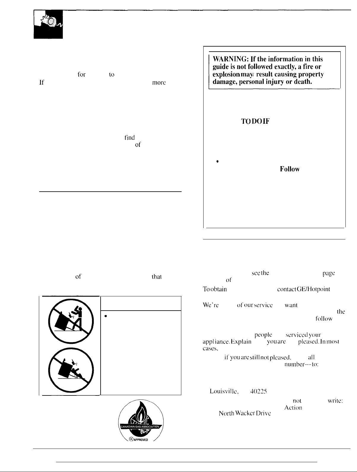
A WARNING
“
ALL RANGES
CAN TIP
● INJURY TO PERSONS
COULD RESULT
● INSTALL ANTI-TIP
DEVICES PACKED
WITH RANGE
● SEE INSTALLATION
INSTRUCTIONS
thai
you
— Installation and service must be
performed by a qualified installer, service
agency or the gas supplier.
IF YOU NEED SERVICE
To obtain service,
the back of this guide.
Tb obttiin
Service Centers.
We’re
pleased. If for some reason you are not happy with
service you receive, here are three steps to
further help.
FIRST, contact the
app] iunce. kixpluin
cases,
NEXT,
details-including your phone
FINALLY, it your problem is still
replacement parts,
proud of
this will solve the problem.
if yOLI arc still no( plcused,
Manager. Consumer Relations
Hotpoint
Appliance Park
Louisvi] [c!,
Major Appliance Consumer
20
Nc)r[h N/a~k~r D1.iv~
Chicago, IL 60606”
see the
ou[” ser”vice
people
why
KY
40225
Consumer Services
cormtct Gt3/Hotpoint
and
wan[
you to be
who
serviced your
yoLl are
not
ptctised. ]11 most
write
all
numhel---to:
not
resolved.
Ac[ion
Panel
the
page
f~~llow
write:
in
[he
for
2
IMPORTANT SAFETY NOTICE
●
The California Safe Drinking Water and Toxic
Enforcement Act
requires the Governor of California
to publish a list of substances known to the state
to cause cancer, birth defects or other reproductive
harm, and requires businesses to warn customers
of potential exposure to such substances.
Gas
appliances can cause minor exposure to
four of these substances,
namely benzene, carbon
monoxide, formaldehyde and soot, caused primarily
by the incomplete combustion of natural
LP fuels. Properly adjusted burners, indicated by
gas
or
“
a
bluish rather than a yellow flame, will minimize
incomplete combustion, Exposure to these
substances can be minimized by venting with an
open window or using a ventilation fan or hood,
●
Fluorescent light bulbs and safety valves on
standing pilot ranges contain mercury.
If your
model has these features, they must be recycled
according to local, state and federal codes.
When You Get Your Range
●
Have
the installer show you the location of the
range gas cut-off valve and how to shut it off
if necessary.
●
Have
your range installed and properly
grounded by a qualified installer,
with the Installation Instructions, Any adjustment
and service should be performed only by qualified
gas range installers or service technicians.
c
Do not
●
●
Locate the range out of kitchen traffic path
attempt to repair or replace any part of
your range unless it is specifically recommended
in this guide.
to a qualified technician,
Plug your range into a 120-volt grounded
outlet only.
prong from the plug. If in doubt about the grounding
of the home electrical system, it is your personal
responsibility and obligation to have an ungrounded
outlet replaced with a properly grounded,
prong outlet in accordance with the National
Electrical Code. In Canada, the appliance must be
electrically grounded in accordance with the
Canadian Electrical Code, Do not use an extension
cord with this appliance,
and out of drafty locations to prevent pilot
outage (on standing pilot models) and poor
air circulation.
All other servicing should be referred
Do not remove the round grounding
in accordance
three-
c
Be sure all packing materials are removed from
the range
before operating it to prevent fire or
smoke damage should the packing material ignite.
●
Be sure your range is correctly adjusted by a
qualified service technician or installer for the
LP)
type of gas (natural or
that is to be used.
Your range can be converted for use with either
type of gas. See the Installation Instructions.
WARNING:
These adjustments must be made
by a qualified service technician in accordance
all
with the manufacturer’s instructions and
codes
and requirements of the authority having
jurisdiction, Failure to follow these instructions
could result in serious injury or property damage.
The qualified agency performing this work
assumes responsibility for the conversion.
NOTE:
the top burners of the
●
After prolonged use of a range, high floor
Need to buy kit WB28KO085 to convert
RGB508,
temperatures may result and many floor
coverings will not withstand this kind of use.
Never install the range over vinyl tile or linoleum
that cannot withstand such type of use. Never
install it directly over interior kitchen carpeting.
Using Your Range
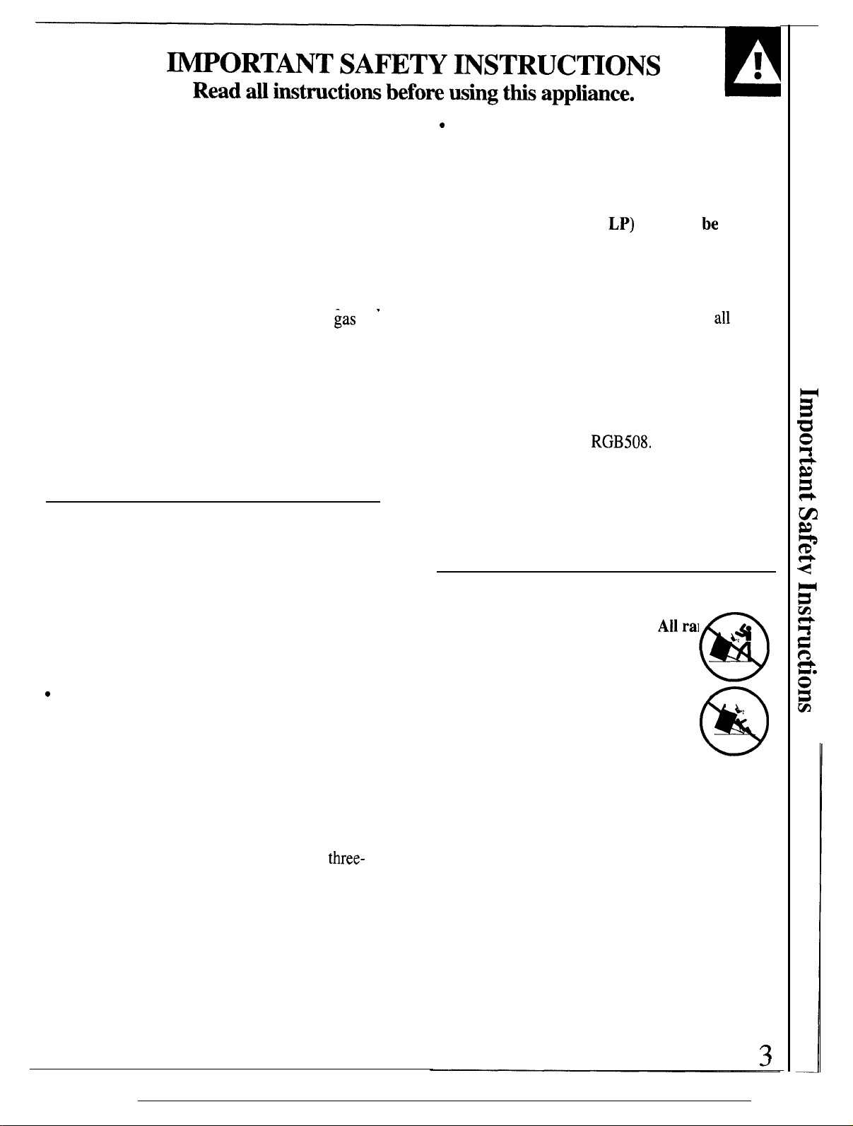
AWARNING—
can tip and injury could result. To
prevent accidental tipping of the
range,
installing the Anti-Tip device supplied.
To check if the device is installed and
engaged properly, carefully tip the range
forward. The Anti-Tip device should
engage and prevent the range from tipping over.
If you pull the range out from the wall for any
reason, make sure the device is properly engaged
when you push the range back against the wall.
If it is not, there is a possible risk of the range
tipping over and causing injury if you or a child
stand, sit or lean on an open door.
Please refer to the Anti-Tip device information
in this guide. Failure to take this precaution could
result in tipping of the range and injury,
●
attach it to the wall and floor by
Do not leave children alone or unattended
where a range is hot or in operation.
They could be seriously burned.
A1lranges .4
@
L,
@
(continued next page)
2
1
●
J
●
CAUTION: ITEMS OF INTEREST TO
IMPORTANT SAFETY INSTRUCTIONS
(continued)
CHILDREN SHOULD NOT BE STORED IN
CABINETS ABOVE A RANGE OR ON THE
BACKSPLASH OF A RANGE—CHILDREN
CLIMBING ON THE RANGE TO REACH
ITEMS COULD BE SERIOUSLY INJURED.
●
Do not allow anyone to climb, stand or hang
on the door, broiler drawer or cooktop. They
could damage the range and even tip it over,
causing severe personal injury.
●
Let the burner grates and other surfaces cool
before touching them or leaving them where
children can reach them.
●
Never wear loose fitting or hanging garments
while using the appliance.
Be careful when
reaching for items stored in cabinets over the
cooktop. Flammable material could be ignited if
brought in contact with flame or hot oven surfaces
and may cause severe burns.
Q
For your safety, never use
your appliance for
warming or heating the room.
●
Do not use
a flaming pan.
flaming pan on a surface unit by covering the
pan completely with a well-fitting lid, cookie
sheet or flat tray. Use a multi-purpose dry
chemical or foam-type fire extinguisher.
Flaming grease outside a pan can be put out by
covering it with baking soda or, if available, by
using a multi-purpose dry chemical or foam-type
fire extinguisher.
Flame in the oven can be smothered completely
by closing the oven door and turning the oven off
or by using a multi-purpose dry chemical or
type fire extinguisher.
●
Do not store flammable materials in an oven, a
range broiler or storage drawer or near a cooktop.
●
DO NOT STORE OR USE COMBUSTIBLE
MATERIALS, GASOLINE OR OTHER
FLAMMABLE VAPORS AND LIQUIDS IN
THE VICINITY OF THIS OR ANY OTHER
APPLIANCE.
●
Do not let cooking grease or other flammable
materials accumulate in or near the range.
●
When cooking pork,
and always cook the meat to an internal temperature
of at least
possibility that trichina may be present in the meat,
it will be killed and the meat will be safe to eat.
water on grease fires. Never pick
Turn the controls off. Smother a
foam-
follow the directions exactly
170”F.
This assures that, in the remote
up
Surface Cooking
●
Always use the LITE position (on electric
ignition models) or the HI position (on standing
pilot models) when igniting the top burners
make sure the burners have ignited.
●
Never leave the surface burners unattended at
high flame settings.
Boilovers
and greasy spillovers that may catch on
●
Adjust the top burner flame size so it does not
extend beyond the edge of the cookware.
Excessive flame is hazardous.
●
Use only
dry pot holders—moist or damp pot
holders on hot surfaces may result in burns from
steam.
●
Do not let pot
holders come near open flames
when lifting cookware.
other bulky cloth in place
●
To minimize the possibility of burns,
of flammable materials and spillage, turn
cookware handles toward the side or back of the
range without extending over adjacent burners.
●
Always turn the surface burners to off before
removing cookware.
●
Carefully watch foods being fried at a high
flame setting.
●
Never block the vents (air openings) of the
range.
are necessary for the range to operate properly
with correct combustion. Air openings are located
at the rear of the cooktop, at the top and bottom of
the oven door, and at the bottom of the range
under the broiler drawer.
●
Do not use a wok on models with sealed burners
if the wok has a round metal ring that is placed
over the burner grate to support the wok.
ring acts as a heat trap, which may damage the
burner grate and burner head. Also, it may cause
the burner to work improperly. This may cause a
carbon monoxide
current standards, resulting in a health hazard.
Q
Foods for frying should be as dry as possible.
Frost on frozen foods or moisture on fresh foods
can cause hot fat to bubble up and over the sides
of the pan.
●
Use the least possible amount of fat for effective
shallow or deep-fat frying.
full of fat can cause spillovers when food is added.
s
Always heat fat slowly, and watch as it heats.
They provide the air inlet and outlet that
level
above that allowed by
cause smoking
fire.
Do not use a towel or
of a pot holder.
ignition
Filling the pan too
and
This
4
—
●
If a combination of oils or fats will be used
in frying,
stir together before heating or as fats
melt slowly.
●
Use a deep fat thermometer
whenever possible to
prevent overheating fat beyond the smoking point.
●
Never try to move a pan of hot fat, especially a
deep fat fryer.
●
Use proper pan
Wait until the fat is cool.
size—Avoid pans that are
unstable or easily tipped. Select cookware having
flat bottoms large enough to properly contain food
and avoid
boilovers
and spillovers and large
enough to cover burner grate. This will both save
cleaning time and prevent hazardous accumulations
of food, since heavy spattering or spillovers left
on range can ignite. Use pans with handles that
can be easily grasped and remain cool.
●
When using glass cookware,
make sure it is
designed for top-of-range cooking.
●
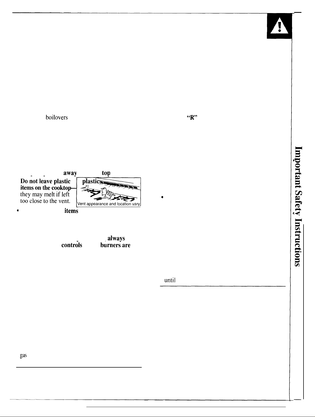
Keep all plastics
● Do not leave
awav
from the
piastic ,.,,.
tot)
burners.
●
Keep the oven free from grease buildup.
●
Place the oven shelves in the desired position
while the oven is cool.
●
Stand away from the range when opening the
door of a hot oven.
The hot air and steam that
escapes can cause burns to hands, face and eyes.
●
pulling out the shelf to the shelf-stop is a
convenience in lifting heavy foods. It is also a
precaution against burns from touching hot
surfaces of the door or oven walls. The lowest
‘<R”
position
●
Do not heat unopened food containers. Pressure
is not designed to slide.
could build up and the container could burst,
causing an injury.
●
Do not use aluminum foil anywhere in the oven
except as described in this guide.
Misuse could
result in a fire hazard or damage to the range.
●
When using cooking or roasting bags in the
follow the manufacturer’s directions.
oven,
●
Use only glass cookware that is recommended
for use in gas ovens.
they may melt If left
too close to the vent.
‘ternson’hec’ktom
Do not leave any
Vent appearance and location vary
item:
on the cooktop.
1
The hot air from the vent may ignite flammable
items and will increase pressure in closed
containers, which may cause them to burst.
●
To avoid the possibility of a burn.
certain that the
contr&
for all burner~are at
alwavs
be
the off position and all grates are cool before
attempting to remove them.
●
When flaming foods are under the hood, turn
the fan off. The fan, if operating, may spread
the flames.
●
If range is located near a window,
do not hang
long curtains that could blow over the top burners
and create a fire hazard.
●
When a pilot goes out
(on standing pilot models),
you will detect a faint odor of gas as your signal
to relight the pilot. When relighting the pilot,
make sure burner controls are in the off position,
and follow instructions in this book to relight.
●
If you smell gas,
and you have already made sure
pilots are lit (on standing pilot models), turn off the
gas
to the range and call a qualified service technician.
Never use an open flame to locate a leak.
c
Always remove the broiler pan from range as
soon as you finish broiling.
Grease left in the pan
can catch fire if oven is used without removing
the grease from the broiler pan.
●
When broiling, if meat is too close to the flame,
the fat may ignite.
Trim excess fat to prevent
excessive flare-ups.
●
Make sure the broiler pan is in place correctly
to reduce the possibility of grease fires.
●
If you should have a grease fire in the broiler
turn off oven control, and keep broiler
pan,
drawer and oven door closed to contain fire
until
it burns out.
Cleaning Your Range
●
Clean only parts listed in this Use and Care Guide.
●
Keep range clean and free of accumulations of
grease or spillovers, which may ignite.
●
Be careful when you clean the cooktop because
the area over the pilot (on standing pilot models)
will be hot.
●
For continuous clean models,
cleaners on any of the continuous cleaning
surfaces. Continuous cleaning surfaces can be
do not use oven
identified by their rough surface finish.
Baking, Broiling and Roasting
●
Do not use the oven for a storage area.
Items stored in the oven can ignite.
SAVE THESE
INSTRUCTIONS
5
FEATURES OF YOUR RANGE
6
.
A
\
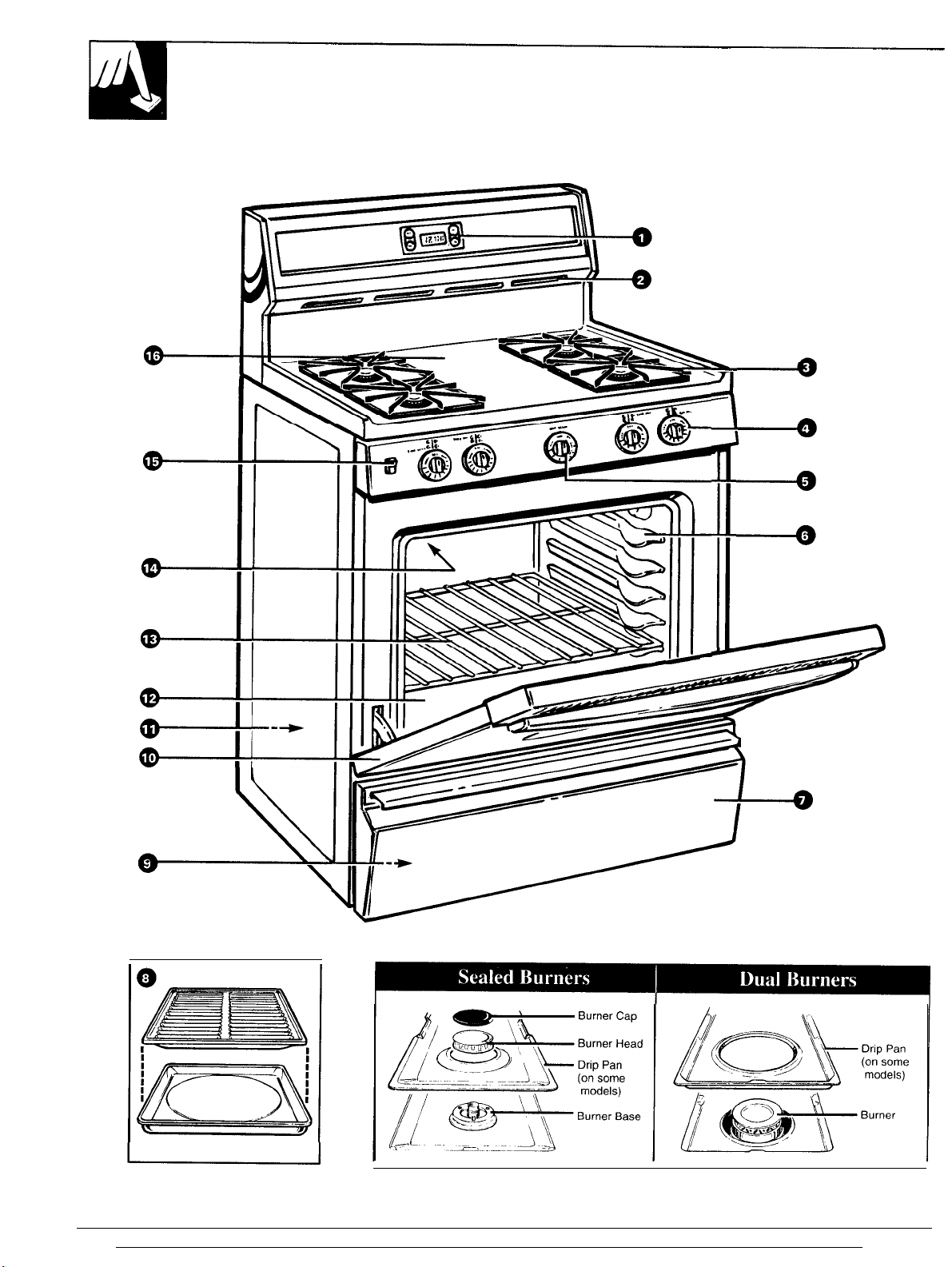
Your range is equipped with one of the two types of surface burners shown above.
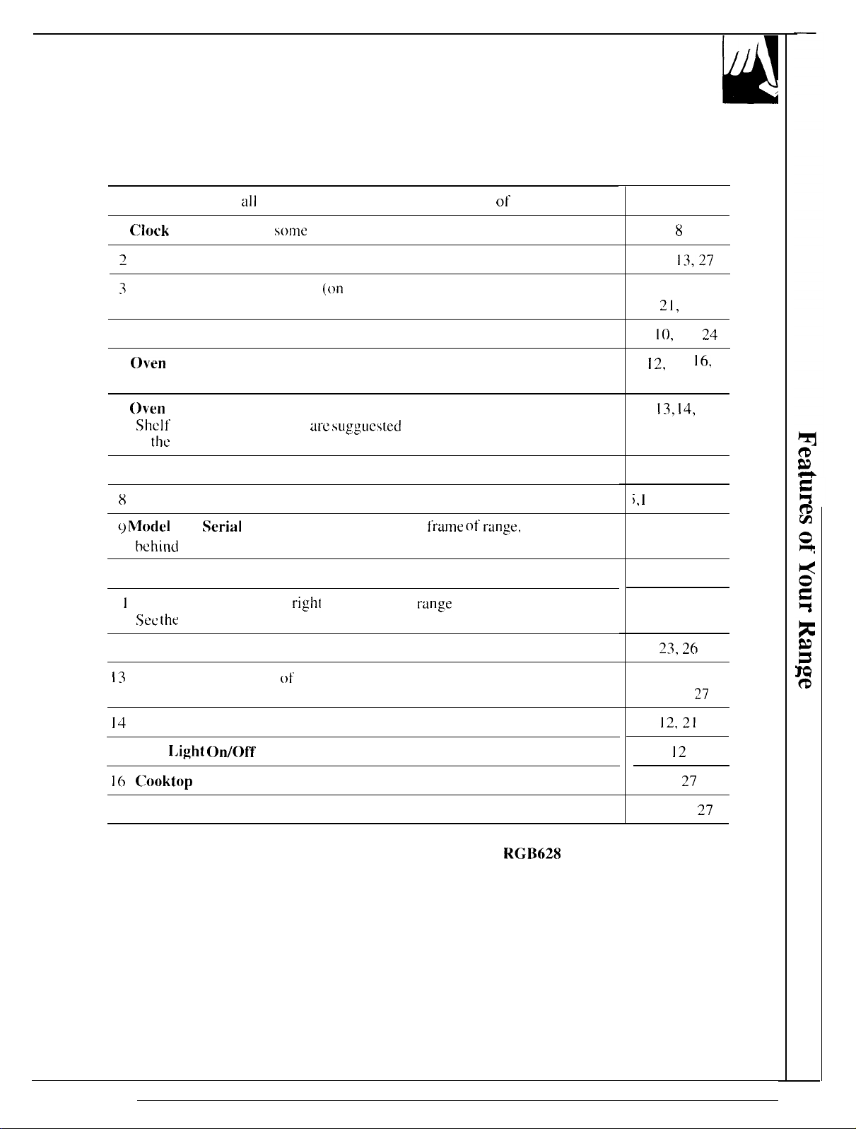
Feature Index (Not
I
Clock
and Timer (on
2
oven Vent
3
Surf’ace Burners, Drip Pans
all
models have all features. Appearance of features varies.)
solne
models)
(on
some models) and Grates
See
page
8
4,5, 13,27
4,5, 9- I 1,
21,
27
4 Surface Burner Control Knobs
5
(lven Control Knob
6
oven
Shelf” Supports
Shelf’
positions for cooking
i n
[he
Baking and Roasting sections.
7 Broiler Drawer
8
Broiler Pan and Rack
$) ModeI
I () Lift-Off oven Door
I
1
Anti-Tip Device (Lower
12 oven Bottom
13
Oven Shelves (number of shelves varies)
14
Oven Interior Light (on some models)
and
Serial
Numbers (located on front
behind
broiler drawer)
Sec [he
Installation instructions. )
are su.gguestecl
right
rear corner on
f“rame Of range,
range
back.
4,
10,
I 1,
24
1 ~,
]4,
l(j,
17, 19,24
5,
13, 14,
17
4,5, 19,20,24
i, i
7, 19, 20, 24
2
19,20,25,26
2, 3,29,38
~~,
~(j
5, 13-15,
17, 26,
27
15 oven
16 C()()kt()p
NOTE: All models have standard oven interiors, except for
which have a continuous-cleaning oven interior. See the Care and Cleaning section for
instructions.
I,ight
Air Vents
on/Of~ Switch (on some models)
RG13628
23,
4, 5, 13,
and RGB630,
12
27
27
7
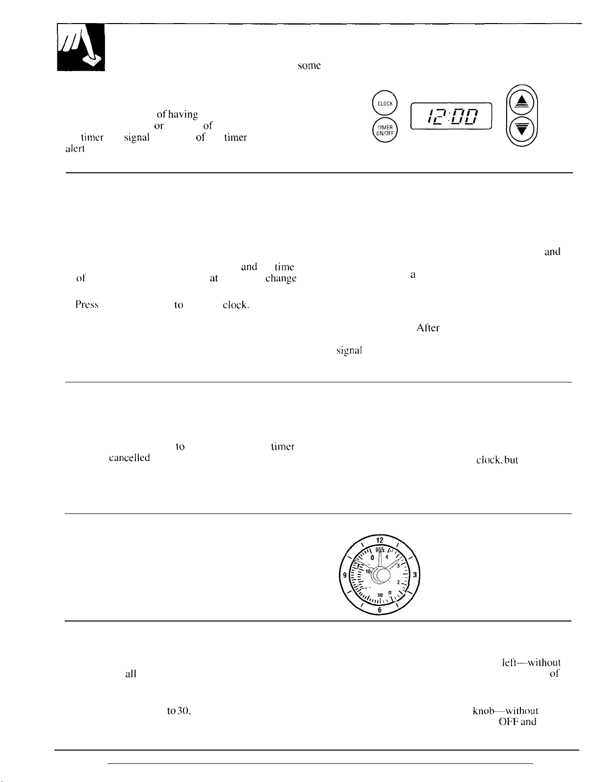
FO11
OW
the directions below if your range has the
clock and timer shown at the right.
You have the choice
time counting down
the timer will
alert
you that
signal
the time is up.
of
having
the timer show the
or
the time of day. In either case,
at the
end of the
CLOCK AND TIMER
(on wme models)
$@@
thmer
period to
(Appearance may vary)
To Set the Clock
NOTE: When you first plug in the range or after a
power failure, the entire Clock/Timer display will
light up.
1.
Press the CLOCK pad.
2. Press and hold the UP or DOWN pad
of day will change 10 minutes at a time. To
the time by single minutes, give the pads short taps.
3.
Press
the CLOCK pad to start the
clock.
and
the
change
tilme
To Change or Cancel the Timer Setting
When the timer is counting down, use the UP and
DOWN pad to change the remaining time, or press
the TIMER ON/OFF pad
cannot be
cwwelled
“set timer” instructions above.
to
stop the timer. The
tilmer
unless you have fully completed
To Set the Timer
1. Press the TIMER ON/OFF pad.
2. Use the UP and DOWN pads to set the timer.
Short taps on the UP or DOWN pad change the
timer’s setting one minute at a time. Pressing
and
continuing to hold the UP pad increases the setting
ten minutes at
a
time.
3. Once you have set your timer, press the TIMER
ON/OFF pad to start timing.
As the timer counts down, a signal will indicate when
one minute is left.
After
this signal, the display will
count down in seconds. When time runs out, a final
signal
wi II sound. Press the TIMER ON/OFF pad to
stop the signal.
To Display the Clock While the
Timer Is Operating
Pressing the CLOCK pad while the timer is operating
will not interfere with the timer’s operation; the
display will change to show the
will continue to count down and will still signal when
time is up. Press the TIMER ON/OFF pad again to
change the display back to show the timer.
clock. bul
the timer
Clock
Follow these directions if your range has the clock
and timer shown at the right. To set tbe clock, push
in the knob and turn it to the right. Let the knob out
when the clock hands reach the correct time. Continue
turning the knob to OFF.
,
Q
\
\.\\\
\.\
o
;10 (-J ::,
*
.-,
20
/<
~,
‘/1,,,1
/
12 ,
OFF
I
I
4 /, /
30
(,,1’ ‘
, \ \
6
,
.
.
Timer
The Timer has been combined with the range clock.
Use it to time
all
your precise cooking operations.
You’ll recognize the Timer as the pointer that is minutes or hours you want to time.
different in color than the clock hands.
Minutes are marked up
to 30,
and hours are marked
up to 4 on the center of the clock. pushing in—until the pointer reaches
To set the Timer, turn the knob to the
pushing in—until the pointer reaches the number
At the end of the set time, a buzzer sounds
to tell you time is up. Turn the
knob-without
buzzer stops.
8
Ieft-wilhout
OFF and
the
ol’
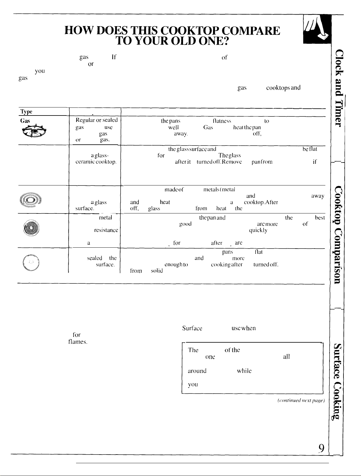
Your new cooktop has
gas
to cooking with induction
units,
yOLI
will notice some differences when you use
gas
burners.
l}p~
of” Cooktop
Gas
Burners
Radiant
(Glass Ceramic)
Cooktop
Description
Regujw
gas
either LP
or
natural
Electric coils
under
ccramic
o
Induction
\\w%,,,
S&J>
-, +/,, ,,
$\.\\\---
“%,,,\i\\
Electric Coil
/ J
@
~-~
Solid Disk
(-)
o
High frequency
induction coils
under
surface.
Flattened njetal–
tubing containing
electric
wire suspended
over
Solid cast iron
disk
cooktop
burners. If you are used
or
other electric surface
How it Works
or s~~le~
burners
gas
a glass-
cooktop.
usc
gas.
Flames heat
pans should bc
heat settings right
Heat travels 10
the bottom
continue cooking
you want cooking to stop.
Pans must be
produced by a magnetic circuit between the coil
a glass
resistdncc
a
drip pan.
sealed
to
surt’ace.
the
and
ot’f”,
Heats by direct contact with
cooking results, usc
warped pans than radiant or solid disks,
heat settings as quickly as gas or induction. Electric coils stay hot enough to
continue cooking
Heats by direct contact with the
cooking results.
disk stays hot
t’rom
changes
the
glass
the
solid
The best types of cookware to use, plus heat-up and
cool-down times, depend upon the type of burner or
surface unit you have.
The
following chart will help you to understand the
differences between
other type ot’ cooktop you may have used in the past.
the puns
for
heat
cooktop is hot
directly. Pan
WCI1
balanced.
away,
When you turn the control
the glass surl’ace and
good cooking results.
after it is
made of’
ferrous
settings right away, I
good
quality pans. Electric coils
flatness
GiIs
burners
turned of’t’. Remove
metals (tnctal
from
the
the pun
is not critical to cooking results, but
hc~t the pan
then to the cookware, so pans must be tlat on
The :I:ISS
that attracts a magnet). Heat is
ike a gas
heat
ot’
the
md by heating the air under
Heats up
f’or
a short time
Heats up
enough to
disk it’ you want the cooking to stop,
continue
af’tcr
pan, so
tind
cools down
cooking
they
patls
must be
more
Ntcr it is
are
gas
burner
cooktop stays hot enough to
the
and
cooktop.
pan, but cooking stops right away.
turned elf.
slowly than electric coils. The
cooktops and
right away and change
oil’,
cooking stops right away.
pan l’rom
quick\y
the surface unit
the pan. Heats up right
Afler turning the control
the
pan. For
arc more
Ilat
turned ol’f,
forgiving of
but does not change
on the bottom for good
Remove the pan
any
if’
away
best
SURFACE COOKING
Lighting Instructions for Electric Ignition Models
Your surface burners are lighted by electric ignition,
eliminating the need
constantly burning
for
standing pilot lights with
tlaITvss.
In case of a power failure, you can light the surface
burners on your range with a match. Hold a lighted
match to the burner, then turn the knob to the LITE
position. Use extreme caution when lighting
burners this way.
surface burners in
failure occurs will continue to operate normally.
The
When
spark. Do not attempt to disassemble or clean
around
An electric shock may result, which could cause
yOLI
use when
electrode of
one
any burner
the
burner is turned to LITE,
while
an electrical power
spark igniter is exposed.
another burner is on.
to knock over hot cookware.
all
the burners
SURFACE COOKING
(continued)
Lighting Instructions for Standing Pilot Models
The surface burners
on these ranges
stunding
must be lit initially.
To
1.
2. Remove the grates and
pilots
light them:
Be sure surface
burner
knobs are in the
OFF position.
(see the Lift-Up
conlrol
have
[hat
Cook[op
lift
the
section).
Surface Burner Controls
cooktop
up
3.
NOTE:
it.
Necessary section
4. Lower
5. Observe
Locate
the two pilot ports
with
a match.
lt’ the
pilot is too high or low. you
Sce
the Adjust
the cooktop.
ready
for use.
pictures in the Problem Solver.
unsatisfactory.
Ii:htcd
the Suri’acc
of
the
Your
but”ners.
call for
and
light
Burner Pilots If’
Installation
sLIrfacc
Compare the
service.
exh
lnstruc[ions,
burners
tlames
II’
any
tlame
of them
can acijust
arc now
to
is
Knobs that turn the surface burners on and off
marked as to which burners they control. The two
knobs
burners. The two knobs on the right control the right
front and right rear burners.
on
the left
conirol
the left front
imcl lef’t
are
rear
Before Lighting a Burner
●
[f
drip pans are supplied with your
should be used at
all
times.
range,
they
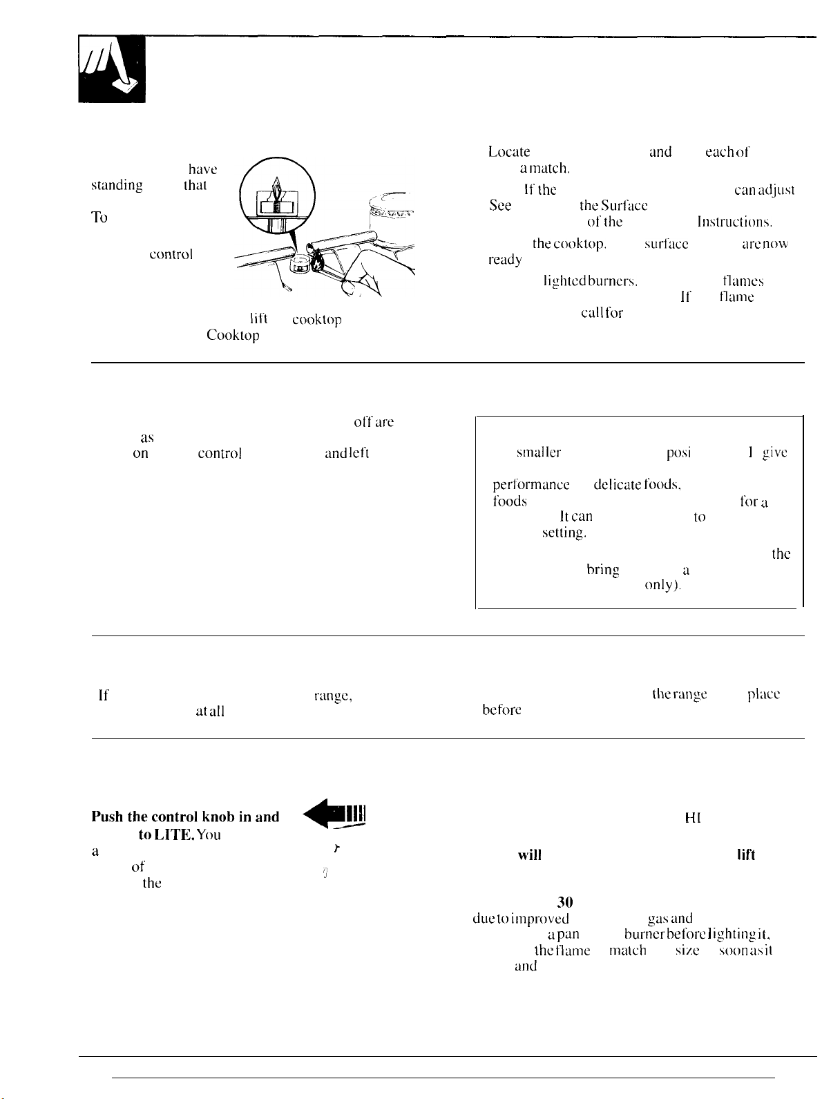
To Light a Surface Burner
Electric Ignition Models:
Pushthe~~ntro]kn~bjn~nd
turn it to
a
little “clicking” noise—the
sound of the electric spark
igniting
LITJL YOLI
the
burner.
will hear
~11~1
,
P
}
j
On ranges with sealed burners:
●
The
sma] ler
the best simmer results. It offers precise cooking
peI-f’Ormance
hods
long time. It
simmer
● The right front burner is higher powered than
others and will
(natural gas instillations
● Make sure all the grates on
bcf’ore
Standing Pilot Models:
Push control knob in and turn it to
The burner should light within a few seconds,
Flame
slightly away from the burner when the burner
is first turned on. A blowing or hissing sound may
be heard for
dLle to impl-oved
burner. put
or adjust
lights.
much less noticeable.
will
and
burner (right rear
for
delicate foods,
which need to cook over low heat
can
be turned down to a very low
set[ing.
bring
liquids to a hoi] quicker
using any burner.
be almost horizontal and will
30
to 60 seconds. This normal sound is
injection of
a pun
on the
the tlmne
the blowing or hissing sound will be
burner before ] ighting it,
to
ma~ch
pc)si
tion ) w i I I
such as sauces or
only).
the range
gas dnd
pan
are in
H[
position.
air into the
size
as
give
for a
the
place
Iif”t
s(mn ~ls il
10
—
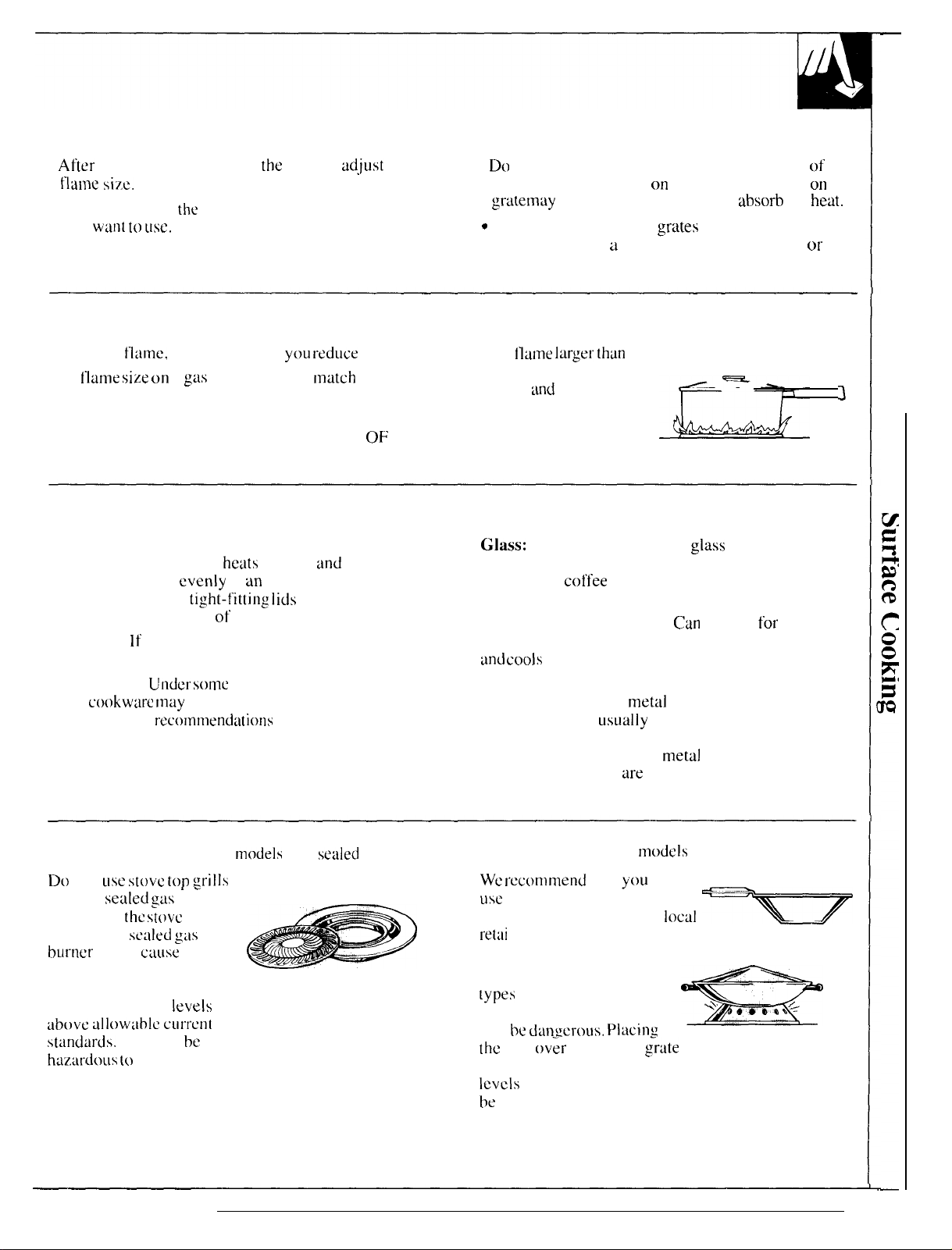
After Lighting a Burner
●
After
the burner ignites, turn
the
flame size.
● Check to be sure
yell
W:lllt to USe.
the
burner you turned on is the one
How to Select Flame Size
knob to
adjust
the
●
Do
not operate a burner for an extended period of
time without cookware cm the grate. The finish on the
gra~e
may
chip without cookware to
Q
Be sure the burners and
place your hand,
a
pot holder, cleaning cloths
grates
absorb
the
heat.
are cool before you
or
other materials on them.
—
Watch the
The
tlanm,
flame size on
not the knob, as
a
g~is
burner should
yOLI I“educe
match
heat. Any
the
cookware you are using.
FOR SAFE HANDLING OF COOKWARE NEVER
LET THE FLAME EXTEND UP THE SIDES
OF
THE COOKWARE.
Top-of-Range Cookware
Aluminum: Medium-weight cookware is
recommended because it
Most foods brown
Use saucepans with
with minimum amounts of water.
Cast-Iron:
If’
heated slowly, most skillets will give
satisfactory results.
Enamelware:
some
cookwure may
manufacturer’s
Under
recotnttlend:ltiolls”
heats
quickly
evenly
in an aluminum skillet.
tight-fittimg lids
some
conditions, the enamel of
and
when cooking
melt. Follow cookware
for cooking methods.
evenly.
Ilame larger thtin
the
bottom of’ the cookware is
wasted
heat the handle.
Glass: There are two types of’
and
only serves to
glass
cookware—those
J
for oven use only and those for top-of-range cooking
(saucepans,
coffee
and teapots). Glass conducts heat
very slowly.
Heatproof Glass Ceramic:
Can
be used
for
either
surface or oven cooking. It conducts heat very slowly
ond COOIS
very slowly. Check cookware manufacturer’s
directions to be sure it can be used on gas ranges.
Stainless Steel: This
properties and is
metal
usLMlly
alone has poor heating
combined with copper,
aluminum or other metals for improved heat
distribution. Combination
satisfactorily if they
metal
skillets usually work
are
used with medium heat as the
manufacturer recommends.
Stove Top Grills (on
IX
not
asc stove top .strills
on your
sealed gas
If’ you use
grill on the
burner
it will
the stove
scaled gas
.-
burners.
top
ctiuse
models
incomplete combustion and
can result in exposure to
carbon monoxide
levels
above ll]]OWllbt~ CL1l’1”~11~
standmts. This can
haz,w”dous (o
your health.
be
with
sealed
burners)
Wok Cooking
We
rtxommend that
usc
only a flat-bottomed wok.
They are available at your
retai
I store.
Do not use woks that have
support rings.
[ypes
of’ woks, with or
without the ring in place.
can be
the
dan~mwus. Placing
ring
ov~r
(on
mocic]s
with sealed burners)
you
local
w
Use of’ these
=
the burner irate may cause the burner
to work improperly resulting in carbon monoxide
ICVCIS
above allowable current standards. This could
be
dangerous to your health. Do not try to use such
woks without the ring. You could be seriously burned
if’ the wok tipped over.
11
USING YOUR OVEN
Before Using Your Oven
Be sure you understand how to set the controls properly. Practice removing
and replacing the shelves while the oven is
tips on the following pages. Keep this
it, especially during the first
weeks
of’ using your
Lighting Instructions for Electric Ignition Models
..-.
ml- -
. . . . . .
1 IN uven uur[ler
l---. --—
mm
J L..
electric ignition.
To light the burner, turn
knob
to
the desired
tempertiture.
light within 30-90 seconds.
selected temperature, the oven burner cycles—off’
completely, then on with a full
selected temperature.
-!l
urou
L-. ...- . . .
uurner are
the
OVEN CONTROL
The burner should
Af”ter the
tlamc-to
oven reaches
cool.
Read
guide h~ndy
,!
..1 ....-, ,.-.
Ikgmeu
uy
maintain
the
information
where you
new rtingc.
the
the
and
can rci”er
to
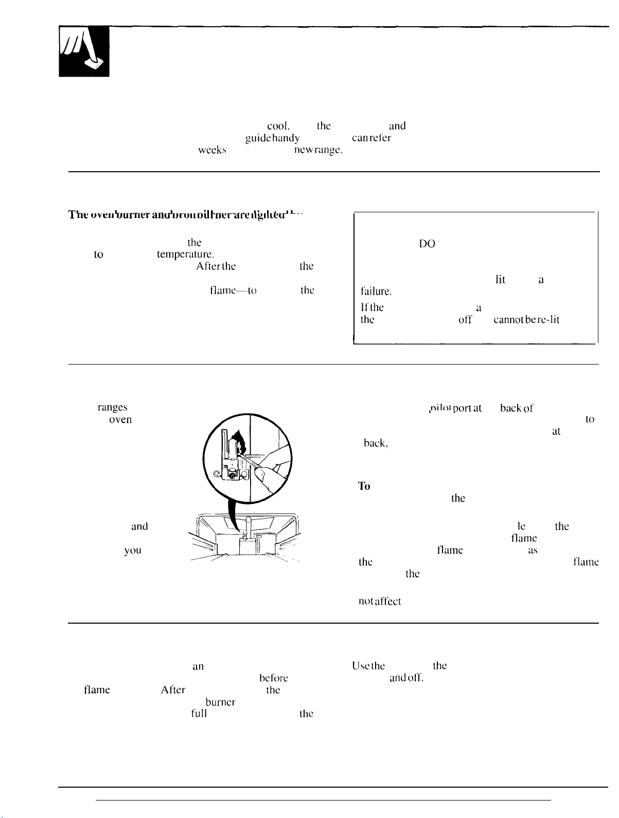
Power Outage
CAUTION: DO NOT MAKE ANY ATTEMPT TO
OPERATE THE ELECTRIC 1GNITION OVEN
DURING AN ELECTRICAL POWER FAILURE.
The oven or broiler cannot be
f’ailure.
Gas will not flow unless the glow bar is hot.
If the
oven is in use when u power failure occurs,
the
oven burner shuts
power is restored,
I
off
lit
during a power
and
canno[ be re-lit
until
Lighting Instructions for Standing Pilot Models
These
ranges
have
standing
o“ven
pilots that compartment. The long tube, running from front
must be lit initially.
To light the oven pilot:
1. Be sure the OVEN
CONTROL knob is
in the OFF position.
2. Open the broiler door
and remove the
broiler pan
and
rack.
This will make it burner, visually check the burner
easier for
yOLI
to
reach inside the
broiler compartment.
Oven Control
Your oven is controlled by
knob. It will normally take 30-90” seconds
the
flame
comes on.
Af’ter
selected temperature, the oven burner cycles—off’
completely, then on with a
selected temperature.
an
OVEN CONTROL
the oven reaches
full
flame—to maintain
bcf’ore
the
the
3.
Find the oven
Dilot mrt at
,,
back, is the oven burner. The pilot port is at the
back,
about one inch below the burner.
4. Using a long match or match holder, reach in and
light the oven pilot.
●
To
light the oven burner, turn the OVEN
CONTROL knob to
the
desired temperature.
The burner should light within 60 seconds.
● Proper flame configuration: Whi
compartment. If’ flame does not burn as described in
the
Installation section of’ this guide, adjust the flame
following
●
Power failure:
not affect
the
directions on those pages.
An electrical power failure wi I I
the standing oven pilot.
Oven Light (on some models)
Use the
light on
switch on
and of’1”.
the
control panel to turn the oven
the
back
of the broiler
lC
using
flame
to
the
oven
in the broiler
12
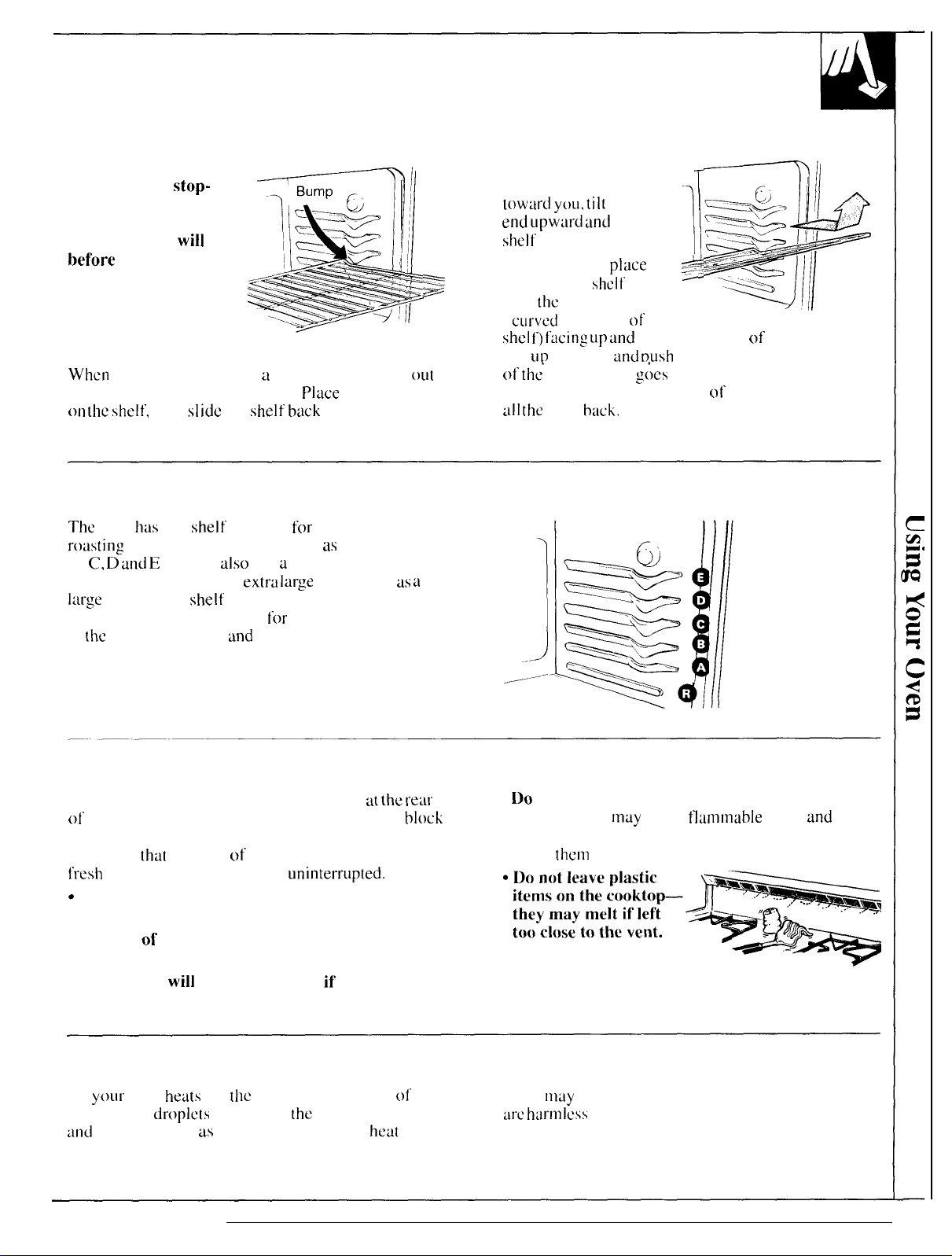
Oven Shelves
The shelves are
designed with
stop-
locks so when placed
correctly on the shelf
supports, they
bef’ore
coming
will
stop
completely out of the
oven and will not tilt
when you are removing
food from them or
placing food on them.
When
placing cookware on a shelf, pull the shelf
to the bump on the shelf support.
on the shelf,
then SI
idc
the shelf
Place
the cookware
back
into the oven.
This will eliminate reaching into the hot oven.
Shelf Positions
The
oven
bus
five
shelf
supports
rodsting
B, C, D
position (R) t-or roasting
large
identified in this illustration as A (bottom).
and E
(top). It
also
extrti large
turkey—the shelf is not designed to slide out at
this position. Shelf positions
in
the
Baking, Broiling
tind
for
baking and
has a special low shelf
items, such as
for
cooking are suggested
Roasting sections.
out
a
To remove a shelf —
from the oven, pull it
toward yoLl, tilt
end
upwmi
shelf
out.
~
~
To replace,
shelf 011 the
with
the
(
cLu”vcd
shcl f)
f’acing
Tilt
LID
the front
of
the’
oven until it
support. Then lower the front
id] the
Way
the front
tind
pull the
place
shcii’
stop-locks
extension
LIp
and
and rrush
hack.
1
the
~
support
of’
>
the
toward the rear of the oven.
the shelf’ toward the back
:L’)CS
past the hump on the shelf
of the shelf and push it
.:
/./.
Oven Vents
The oven is vented through duct openings at
of’
the cooktop. See the Features section. Do not
these openings when cooking in the oven-it is
important
fresh
c
The vent openings and nearby surfaces may
that
the flow of hot air from the oven and
air to the oven burners be
LlninterrLlpted.
become hot. Do not touch them.
● Handles
of’
pots and pans on the cooktop may
become hot if left too close to the vent.
● Metal items
will
become very hot
if’
on the cooktop and could cause burns.
the rear
they are left
Oven Moisture
As
yoLu”
oven
he~ts
up.
the
temperature change of the air in the oven
cause water
Lmd
will evaporate as the oven continues to
tiroplcts
to form on
the
door glass. These droplets art
heat
block
up.
●
Do
not leave any items on the cooktop. The hot air
from the vent
may
ignite tlammable items
and
increase pressure in closed containers, which may
cause
them
to burst.
“~;;::~;k;~-ja~
too close to the vent.
*4
Vent appearance and location vary
rndy
hw-mlcss
will
13
BAKING
Your oven temperature is controlled very accurately
using
an
oven control system. It is recommended that
you
operate the oven for a number of weeks to
become familiar with your new oven’s performance.
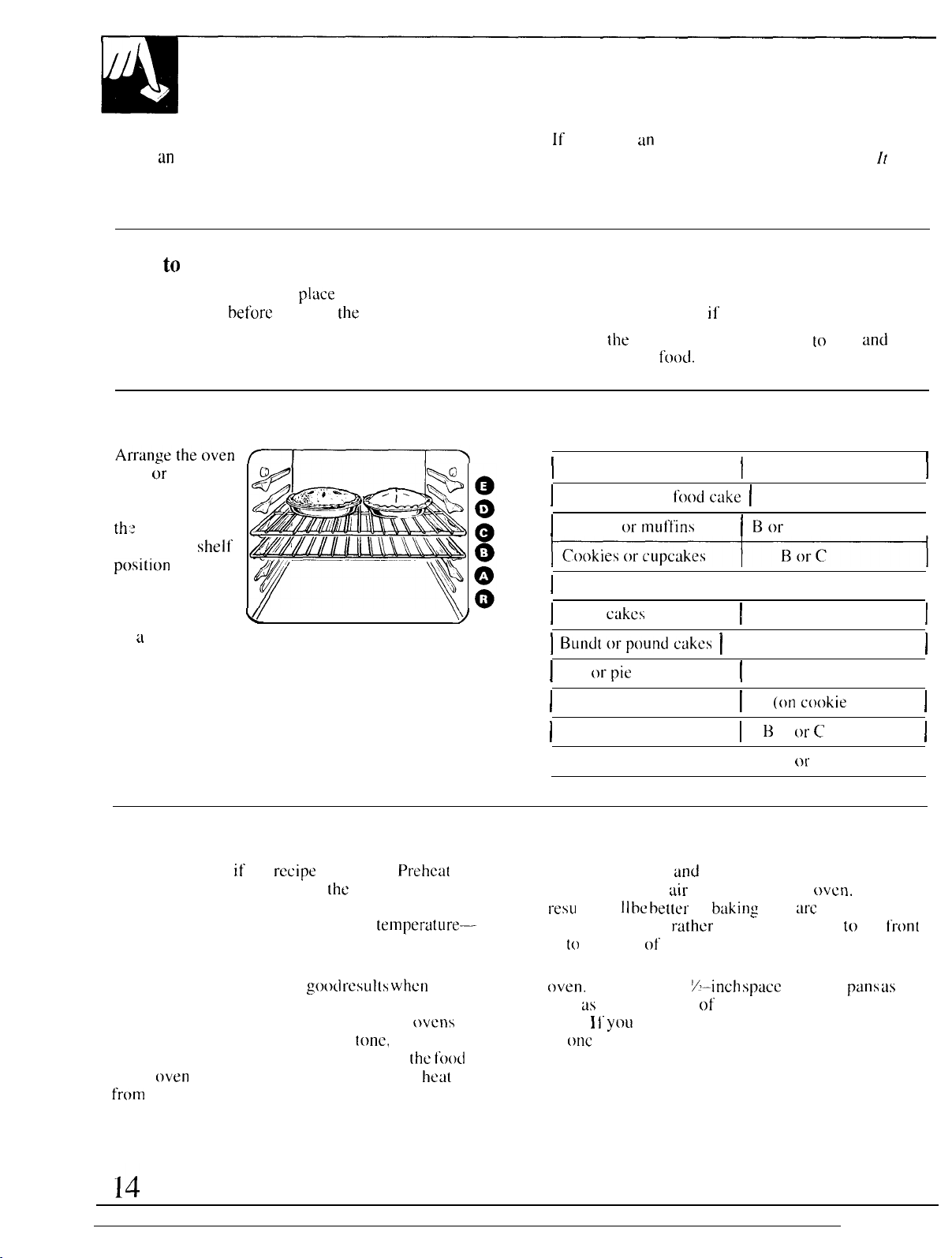
How to Set Your Range for Baking
To avoid possible burns,
correct position
1. Close the oven door. Turn the OVEN CONTROL
knob to desired temperature.
before
place
you turn
the shelves in the
the
oven on.
Oven Shelves
shelf & shelves in
the desired
locations while
th: oven is cool.
The correct
positiorr
on the kind of’
food and the
browning desired.
As a general rule,
place most foods in the middle of’ the oven, on
either shelf’ position B or C. See the chart for
suggested shelf’ positions.
shelf-
depends
VI
\y
If
you think
the Oven Thermostat section. It gives easy
Yourself
tin
adjustment is necessary, see the Adjust
Do
instructions on how to adjust the thermostat.
2. Check food for doneness at minimum time on
recipe. Cook longer
3. Turn
I
\
Type of Food
]
Angel loodcake I A
I
Biscuits ormutfins
]
Brownies
]
Layer
] B~l[ldt[,*pt,undcakcs ]
I
Pies
I
Frozen pies
the
OVEN CONTROL knob
then remove
ctikcs
,,rpie
shells
f’ood.
ii-
necessary.
to
OFF and
1
I
Shelf Position
I Bor
C
B or C
I I
~
B orC
A orB
[
B orC
I
A (oncookie sheet)
It
f
I
I
I
I
I
I
I
Preheating
Preheat the oven if the
means bringing the oven up to
temperature before putting the food in the oven.
To preheat, set the oven at the correct
selecting a higher temperature does not shorten
preheat time.
Preheating is necessary for
cakes, cookies, pastry and breads. For most casseroles
and roasts, preheating is not necessary. For
without a preheat indicator light or
minutes. After the oven is preheated place
in the
oven
as quickly as possible to prevent
from
escaping,
recipe
calls for it.
the
specified
go(xl
resLIl(s
tone,
Prehea[
temperature-
when
baking
ovens
preheat I ()
the i’oocf
heat
/
Casseroles
Rousting
I
I B O*.C
B or R
I
Pan Placement
For even cooking
enough room for
resu
Its wi 11 be better if-
much as possible
or
(()
the back of the oven.
Pans should not touch each other or the walls of the
oven.
Allow I -- to I
well
tis
from the back of the oven, the door and the
sides.
] i“ yoLi
so
onc
is not directly above the other.
and
proper browning, [here must be
tiir
circulation in the
bakin:
pans
r-tither
than being placed [o the
YLincb space
need to use two shelves. stagger the pans
oven.
arc
centered as
between
Baking
front
pans as
I
I
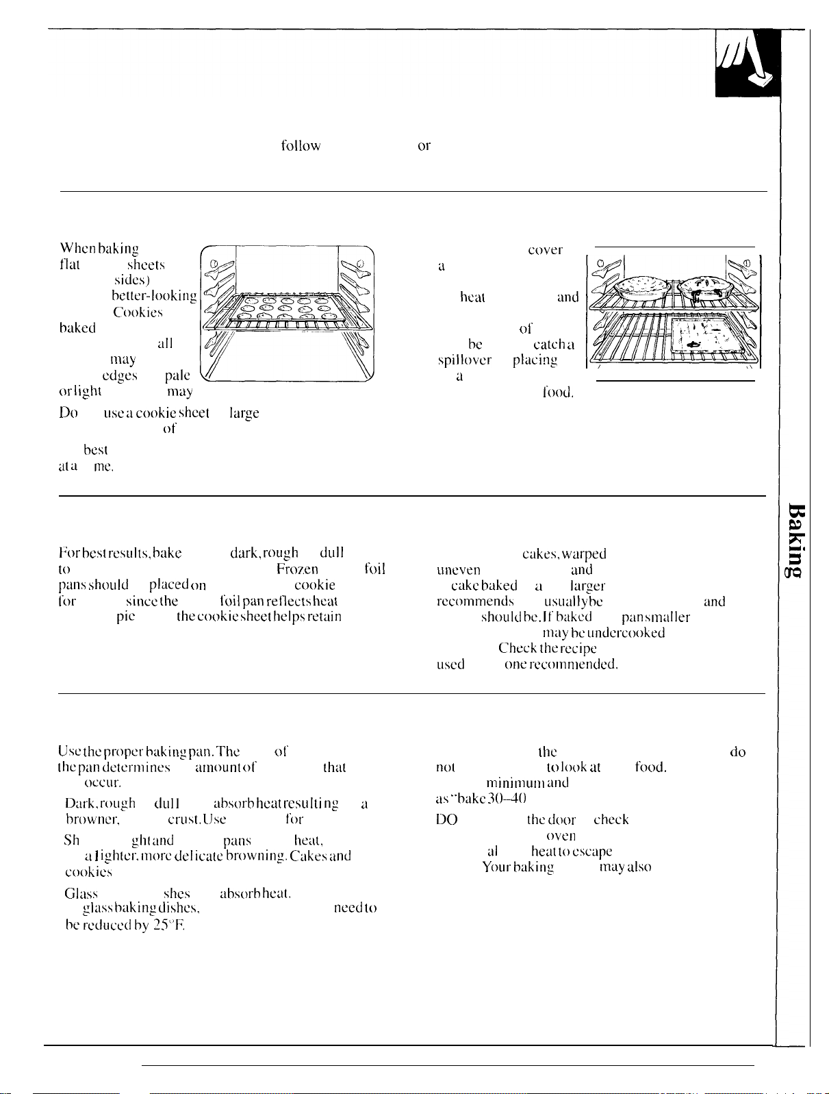
Baking Guides
When using prepared baking mixes,
instructions for best baking results.
Cookies
When baking cookies,
fl~t
cookie
(without
produce
cookies.
baked
pan (short sides
around)
darker
{~r light
Do
not
sheets
sides)
bet[cr-looking
Cookies
in a jelly roll
[ill
may
have
edges
and
pale
browning
may
usc a cookie sheet
occur.
so
large
that it touches the
walls or the door of the oven.
For
best
results. use only one cookie sheet in the oven
at a
t i
Inc.
Pies
follow
package recipe
or
Aluminum Foil
Never entirely cover
L
shell with aluminum
foil. This will disturb
the
heat
circulation
result in poor baking, A
smaller sheet
may bc used to
spillovcr
on
u
lower shelf several
by
of foil
catch u
placing
inches below the
Cakes
and
it
food.
}Jor
best
l“esLllts, hake pies in
to
produce a browner, crisper crust.
puns should
for
baking
from the
be
placed (JI]
since (he
pie
crust;
shiny
the cookie sheet helps retuin
dark, rou,gh
an aluminum
foil pun reflects heat
Baking Pans
Use the proper huking pan. The
the
pm
dctcrm ines
will
OCCLII”.
●
Dw”k, rough
browner,
●
.Sh
in a 1
cookies
●
CJI:lSS
in
be
crisper
i ny, bri
ightcr. tnt)rc LIel icatc browning, Cukes and
require this type of pan.
baking d i
gl~iss b~lking Llishcs,
l-CdLILW[ hy
or
dLI I ]
gill und
25’)[;.
the
amount
pans
crust, lJse
smooth
shcs
also
type
of browning
:ihsorb heat resu Iti n:
this type
p~ms
absorb heat,
the temperature may
Frozen
o(’
reflect
or
dLI]]
pans
pies in
cookie
sheet
away
it.
finish on
[hat
i n
for
pies.
he:l[,
resulting
When baking
need to
toil
a
When baking
uneven
A
baking results
c:ikc baked
rccomlmencls
than it
cukes, warped
in a pan
will LISLItIlly
should be. It’
recommended. it
overflow.
LISLXI
C’heck the recipe
is the one
rux)mn]ended.
Don’t Peek
Set the timer for
not
open the door
provide
2S
DO
time. Opening the
cooking a] lows
longer.
minimunl and
“bake ~()–d()
NOT open
YOLII- baking
minutes.”
the d(wr
hetit to csctipe
or bent pans will cause
and
poorly shaped products.
larger
than the recipe
t-w
crisper, thinner
bakul in a pm
nl:ly be undcrc(mkeci
smuller
and batter may
to make sure the pan size
the
estimated cooking time and
ICJ look at
your
food.
Most recipes
maximum baking times such
to
check
until the minimum
oven
door frequently during
and makes baking times
results
may also
be affected.
and
than
drier
do
15

ADJUST THE OVEN THERMOSTAT—
DO
You may feel that your new oven cooks differently
than the one it replaced.
use your new oven
familiar with it, following the times given in your
recipes as a guide.
If you think your new oven is too hot or too cold,
you can adjust the thermostat yourself.
it is too hot, adjust the thermostat to make it cooler.
[f
you think it IS too cool, adjust the thermostat to
make it hotter.
We do not recommend the use of inexpensive
thermometers, such as those
to check the temperature setting
These thermometers may vary
We
recommend that you
for
a few weeks to become more
found
in grocery stores,
of your new oven.
2040” degrees.
IT
If
you think
YOURSELF!
To Adjust the Thermostat:
(appearance may vary)
Pull the OVEN CONTROL knob off the range and
look at the back side.
To
make adjustment, loosen (approximately one turn),
but do not completely remove, the two screws on the
back
of’
the knob. With the back of the knob
you, hold the outer edge of the knob with one hand
and turn the front
To
raise the oven temperature, move the top screw
toward the right. You’ll hear a
you move the knob. To lower the temperature, move
the top screw toward the left. Each
the oven temperature approximately 1 ()”F. (Range is
plus or minus
We suggest that you make the adjustment one
from the original setting and check oven performance
before making any additional adjustments.
After the adjustment is made,
are snug, but be careful not to overtighten.
knob on range and check performance.
of the knob with the other hand.
click
for each notch
click will
600F. from
the arrow. )
retighten
facing
change
click
screws so they
Re-insttill
16

Rtms(ing
poullry cun be roasted
Roasting temperatures, which
steady,
is
keep
cxmking
by dry
uncovered in yoLIr oven,
sp:l[lering to a
hcot. Tender meat or
should be low
m
inirnum.
The tJ\cn has a special
low shell’
jLMt
hot[om,” (Jsc
cx[ru
needed.
when
[urlwy.
Licsigned (()
this
1.
(R) position
:lboVC thC OVCI1
i[ when
cx)oki ng space
Ii)r example,
ro:lsti ng
a
The shell’ is
slide out
posi[ion.”
Posi[i~)n OVCII
ut
( B )
posit i~~n for
snml
I
size roast
(3 105 Ibs.
(R)
)
position”
for
lmge
shcl(’
:md a[
is
no(
111
larger ro:lsts.
2.
Check (hc weight ot’ the r-(mst. Place
I’at-side-up or the poultry breast-side-up on
roasting
baste
mea{ :is possible,
pan [’or
rwk in a
the
meat,
this. )
shaliow pun.
Select u
( Broiler
The melting
pan
as
pun
with
close to
r:wk
and
the
rne~it --
the
t’at
the size of
is a
will
good
Ro:~s[ing
Th~r~l’ott (Iw
(YoLI nmy
is
rc:illy :1 h:~king
oven controls
procedure
are set for
hear a slight clicking
oven is working properly,)
M(v+t me:lts
id’tcr
stand in:
:Il]ows rxxlsts to
carve.
It’
you wish to
remove
tcmpcraturt is 5’
shown
Remember that
oven
continue to
being
removed
time for roasts
firm up
Intcrndl temperu[ure
compensate
the roast
from the
[() I ()’)F. less
in the
R(mst ing
food
and
thcrel’orc
shoLIld be removed when
cook
slightly while standing
from
the
is 1 () to 20 minutes. This
:mcl makes them
will rise
for
oven
than temperature
GLI
idc.
will continue to
dcsirccl intcrn:i] tempcra[urc has
3.
Turn the OVEN CONTROL
(temperature,
temperatures
Scc the
Roasting Guide
wld approxi rna(e
4. When Roasting is finished.
CONTROL
knob to OFF
and
I’r-orn the oven.
used f’or meats
Baking.
sound
indicating
oven.
Recornmcndcd
easier
about
5“ to 1
temperature rise,
when its
been
intcrnu]
cook
in
r-cached.
knob to the desired
for
cooking
[urn the
then
times.
OVEN
remove
the
to
()(’F.
the
hot
the
the food
—
Dual Shelf Cooking
This
:dlows more
While
roasting ii
equipped )
cooked” :It
dishes to
iidditional
the
complctc cxx)king
cooking t i
Use of Aluminum Foil
YOLI can LISC
This makes
marinating.
cul”cd meats ot” Il:lsting t’(md dur”ing
the
t’t~il lightly :Iround the
than
one food 10 be cookccl at
20-lb.
Inuy hc xJded
swnc
time.
rnc for
al LinlinL!m
foil to
clcml-up c:isier
c(x)king
with fruits,
turkey
on
shelf position
on position D so
L’u]cu]atc? the total
at
the same time.
the
potatoes.
line
when
cooking hc:lvily
inside of
the
R, a second
th~t
seal loped potatoes cm
cooking
Allow 15-20 minutes
the
broiler
llsing the
cooking.
pan.
pan
Press
for
the pan,
(tc)~lri})lf[,[l lfcll p~~,qc)
swnc
time. For example:
shell’
( it’
time to enable both
s()
01”
be
17
—

Questions and Answers
Q.
Is it necessary to check for doneness with
meat thermometer?
A. Checking the finished internal temperature
completion
Temperatures
roasts over
hour intervals
of cooking time is recommended.
tire
shown in
8
lbs., check with thermometer at
after
half the
Rmts[ing Guide.
time
has passed.
Q. Why is my roast crumbling when 1 try
carve it?
A. Roasts are easier to
Z(J
minutes
cut
across
after rernov
the grain of the meat.
slice
it allowed m coo] 10
in:
tl-olll
OY’CI1. !dC SLI1-C [()
ROASTING GUIDE
Frozen Roasts
ROASTING
(continued)
to
a
a(
the
For
half-
to
Q.
Do I
a
A. 1( is not necessary 10
Q.
When buying a roast, are there any special tips
that would help
A. Yes.
f)r
Q. Can I
roasting a turkey’?
A.
Setiling (I1c
it unsealed allows
the
need
to preheat my
roast or poultry?
me
Buy
bllj’ 1-01 led
seal
I1lCLII.
a roast
:is ctctl
[“oasis.
the sides of-my
foil
wil
oven
each time I cook
pt”chca( youl”
oven
cook it more evenly?
in
I steam
[hc
air to
[Ilickncss
f’oil
[he meat.
circula[c :md brown
as
“tent” when
I.taving
possihle,
Frozen roasts of beef, pork, lamb, etc.,
can
be started
without thawing, but allow 15 [o 25 minutes per pound
additional time (15 minutes per pound for roasts under
5 pounds,
more time for larger roasts.)
‘1’emperature
oven
Doneness
Meat
Tender cuts: rib, high
tip, rump or top
round’!’
quality sirt~)in
325<’
Rxc:
Mutiurn:
well
Lamb
leg
or bone-in
shouldcl”’::
325”
Rw”c:
Medium:
well
VeJl
shoulder,
Pork
loin. rib or shoulder’
Ham, precooked
leg or loin’!:
<
325”
325<’
.325(’
Well [l)ne:
Wctt Done:
T() Ww”m:
Poultry
surv
325’
.350’”
3:5[’
“~:ll”c
ivc.”
Wcti
Well Done:
Wcli
bccl’
is
(Sour-cc:
populw”, but y{)Ll sh[mtd know” (hill co~)kirlg it [~) 011[}” i J() ‘[ tlw;II”I\
Sa!dkmxi Bm)k.
Chicken or
Chicken
Turkey
tThc U.S.
some
food
Duck
pieces
Dcpurtmcnt ol’
poisoning
AgricuttLlrc SJyS
orjymisms nl:iv
Done:
Done:
Il)rw:
D(mc:
Make sure poultry is
thawed
Unthawcd poultry often
Some commercial
succcssfu
given on packagt Iilb
1 Iy w i
frozen
th~)ut
Cl.
thawing.
Approximate Roasting
in Minutes
3
to 5 Ibs.
?4--35
per
Pound Temperature
35-39
.39-45
2
I
--25
25-30
30-35
35-45
35–45
I
X-2.?
minuks pcr pound (ml} weight)
3
to 5
Ibs.
35-40
35--.$()
10 to 15
I (>-22
Your
11)s.
Kitchen
[;uidc.
before
does
not cook evenly.
rf)as[ing.
poultry can be co(ked
F(J1
low
cii rcct ions
Time
6
to 8 Ibs.
1
x
25
~~.-.j 1
.31 –.3.?
2( )-- 2.3
242X
2X
33
30-40”
30--W
Internal
I
40”- 1 50(’”1”
1 .50” ‘- I
I 70’’ -- I
I 40”- I
I 50”- I
70”- I
70”- I M“
70” ‘-~ I
I
over 5 lbs.
30- .35
X5’ I
X5”
OJcr 15
USDA
] ~. } ()
lbs.
Rc\. .lurw
In thigh:
I
X5’ ‘
I ‘)X5. )
5“-
I ~)()”
60’”
X5”
50” ‘“:”
()()’
X5’
X()”
I
25”
()()
I
~X”
‘l;.
18

Broil in: is cooking food by
food.
Most fish and
Follow [hew
to a minimum.
Your
broiling, A specially
allow
keeps it
1.
You can
heat source by positioning
on one
compartmen-A
B
(middle) and C (top).
2.
Preheating
cim
3
. .
It’
meat
vertical
do
not
trim
layer about 1/8 irlcb
directions (o keep
range
has a compartment
clrippi ng
away
change the
of
three shcl
produce poor results.
has fat
sltishcs
CLI[
into the meat.
fat to
prevent excessive smoking. leaving a
[endcr
designed broiler pan
fat to drain away from
I“rom the
the
high
distance
f positions i n
(bottom of broiler compartment),
broiler or
or gristle around the edge, cut
through it about 2
thick.
Llirec[ beat fr(>m above
cuts of meat
spiLttering and
below the
heat
of
of’ the
the
oven
is
We
recommend that you
cim be
oven
and ruck
the food tind
the giIs flame.
food from the
broiler
pun and
the
broi
no[
necessary and
inches
ICI”
apart;
the
broiled.
smoking
for
rack
Both the oven and broiler compartment doors
should be closed during broiling.
Turn most
is thin fillets of fish;
on broiler- rack
Time
turn
4.
Arrange the food on the rack and position the
broiler pan on the appropriate shelf in the oven or
broiling
[lime
also increases
imd
Close the oven and broiler compartment door.
5.
Turn the OVEN CONTROL knob to BROIL.
6.
Turn OVEN CONTROL knob to OFF. Remove the
7.
broiler
food irnrnaliiitely.
to cool.
foods
once during cooking (the exception
oil
one
side,
place that side down
and cook
foods
for about one-half the total cooking time,
food,
then continue to cook to preferred doneness.
compartment. Placing food closer to the
increilses
meat j u ices igniting.
pun
exterior browning of the food, but
sptittering
from the broiler compartment and serve
without turning until done).
and the possibility of fats
Leave the pan outside the range
Use of Aluminum Foil
YOLI can LISe
broiler rack. However-, you must mold the
to the
Without
juices from
could
not cut
aluminum
rack imd
becornc
the
the
slits,
ciraining
hot enough to
slits, yoLl are frying, not broi I i
foil
to line your broiler pan and
CLlt slits
in it just like
the
foil will prevent
to
the
broiler- pan. The
~iit~h
the rii~k.
on
fat
fire.
Questions and Answers
~. When broiling, is it necessary
rack in the pan?
A.
Yes. (Jsing
pun.
thus
rii~k ilnd
spatter and
Should I salt the
Q.
A.
N(). salt
cvapor-a(c. Alwil~\ sal[ at’ter cookir]g. TurIl the
meat with
a]
low’s
I’ish,
the
ril~k sllspends [hc meat
As
[he
meat cooks,”
keeping
brush each side often with butter.
meat
stay
c(mlcr.
sm(~k
i
dl”LIWS 011[ (hc jLli CCS
(ongs; picrc
j u
ices [() esc’apc. When
the juices
Lir-icr. Juices
thins prevcnti
ng.
meat bef’ore
in: the
to
always use a
over the
fall into the pan,
are protected by
rlg cxcessi vc
broiling?
and il]lows
]nc~t
with il fork also
broi I i ng
foil
tightly
and
m~iit
juices
If you
ng.
thCITl [()
pou
I try or
do
the
Q.
Why are my meats not turning out as brown as
they should?
A.
Check to see if’ you are using the recommended
shelf position. Broil
indicated in the Broiling Guide. Turn the food only
once during broiling.
for-
the longest period of time
I
I
I
19

BROILING GUIDE
The oven and broiler compartment doors must be
closed during broiling.
● Always use the
your
t%lge. 11
spattering by trapping
hi Ier
pm and rack
tha[
comes with
is design&i to minimize smoking and ● When arranging the food on the pan, do not let
.ju ices
in the shielded lower
part of’ the pan.
●
l% s[eaks
[Jutsidc
through the outer fal
meat. Use
piercing
Food
Bacon
Ground Beef
Well
Beef Steaks
Rare
Medium
well
Chicken
Bakery Products
131”L!ad (Toxs[)
1“’oastcr
Enxlish Mul’[’ims
I,obster Tails
Fish
Ham
Prccook(xl”
Pork Chops
Well
Iamh Chops
Medium
well
Medium
W(211
Wieners,
similar
sausages, bratwurst
and chops, slash
edges
tongs
Ihe meat und losing
Done
[)()[1C
01”
Pastries
Slims
Done
DOIW
Done
prcc<x)kcd
ol”
[he meat.
To slash. cut crosswise
surface just (o the
to
[urn
the
Quantity
Thickness
I
/2-lh.
(aboLI( 8
(4 patties)
I -lb.
1/2 (o
3/4-inch thick
I -inch
[hick
( 1- I x
lhs.
1
Y-inch
(2–2X
Ibs. )
I
whole
(2 (()
27-lbs. ),
spl
i (
Icngthwisc
1 -lb.
I’illcts
l/~-illch thick
1 -inch
thick
2
( I
/2-inuh
2
( I -inch (hick).
;lbo Llt [ lb.
2
(
I
-inch)
.ibout I
()– 12
2
( I Y-inch),
.Iboll[
1 lb.
I -lb.
pkg.
fat evenly
tncfit
over to
juices.
and/or
thin st ices)
)
thick
l/4 to
)
oz.
(
10)
around
edge
prevent
Shelf
Position
B,
B,
of
B
A
B
H
A
B
A
A
A
c
R
the
[he
c
20
1st Side
Minutes
3 Y
1 ()-l 1
9
I’2
13
10
1 2– I 5
25
30-35
I
3–
5 5
x
10
l.?
8
10
1
()
17
I
●
If’
desired, marinate meats or chicken before
broiling. Or brush with barbecue sauce the last
5 to lo-minutes only.
edges
hang
over the sides because dripping
soil the oven.
●
The broiler compartment does not need to be
for
preheated. However,
increase browning, preheat if” desired.
s
Frozen steaks
at
the next lowest shelf position and increasing the
cooking time given in this guide
2nd
Side
Minutes
3
4-5
7
5–6
X-9
6-7
10- I 2
16-18
~5–30
1/2-1
1
f)
lx)
turn over.
8
4-5
9–1 2
4-7
1 ()
4–6
]~_]4
not
can
Comments
Arrange in single layer.
Space evenly. Up to 8 patties
tibout
Steaks less than I -inch cook through
before browning.
Pan
Slash
Reduce times
per side for
side with melted butter.
side-down
Space
cut-side-up and brush with butter,
it’ desired.
Cut through back
open. Brush with
before
broilin~
Handle and turn very carefully. Brush
with lemon butter
cooking, it’ desired. Preheat broiler
increase browning.
Increase times 5 to 10 minutes
[“or 1 X-inch
Slash
Slash
If’ desired, split sausages in
lengthwise; cut into 5 to 6-inch pieces.
very thin foods, or to
be broiled by positioning the
1 X
same time.
frying
is recommended.
t~t.
about
5 to 10 minutes
cut-up chicken. Brush
first.
evenly. Place English muffins
ot’
shell,
melted
broiling and
time.
thick or home cured.
tat.
fat.
atier half’
before
fat could
times per
take
Broil
with
spread
butter
01’
and during
per side
half
tatty
shelf
side.
each
skin-
to

proper care and
and
satisfactory service.
help assure safe and proper maintenance.
BE
SURE ELECTRICAL POWER IS DISCONNECTED BEFORE
c]eaning
are important so your
Follow
these directions carefully in
range Wil]
give yoLI efficient
caring for
it to
CLEANING ANY PART OF YOUR RANGE.
CAUTION: DO NOT OPERATE THE BURNER WITHOUT ALL BURNER PARTS AND DRIP PANS
(IF SO EQUIPPED) IN PLACE.
Sealed Burner Assemblies
(on some models)
~Grate
/
/
/
[-J
Turn all controls OFF before removing burner
parts and drip pans (if so equipped).
The burner grates, caps, burner heads and drip
pans (if so equipped) can be lifted off, making them
easy to
clean.
Burner
Lift off
cfips
with
30
minutes and scour with a plastic
scouring pad to remove burned-cm food particles.
Dry them in a warm oven
do not reassemble them wet.
Caps
when cool. Wash burner The
in hot, soapy water and rinse
clean
water. If desired, soak up to
.
‘..
@
\\
/
~,,......._..J.J
(on sealed burners only)
or
with a
cloth—
Burner Base
The electrode
spark
igniter is cxpostxi.
When one burner is turned
to
LITE.
spark. Do not attempt to
disassemble or clean
burner while mother burner is on. An electric
shock muy
over hot cookware.”
Burner Base
burner
burner fastened to the cooktop) may
cleaned
cleanser. Clean all food residues
around spark electrode. Do not use steel
wool: small bits of steel
clectrodc. Rinse well.
with a
of
the
all the burners
aroun
resLllt,
which coLIid cause yoLI
(on
sea]ed
base (the part of
soft
brush and a mild
wool will
Electrode
burners
the
short out
>
-
only)
from
-.””
[()
knock
Ix e
0
“’”– “-”-””
[he
(Cfmli}ll(cd
Ii(,.11 /MI,qr

CARE AND CLEANING
(continued)
Burner Heads (on
The holes in the burners of your range, and
electrodes, must be kept
ignition
You should clean the burner heads routinely,
especially after
holes. Wipe off burner heads. 11 heavy spillovcr
occurs, remove burner
Remove the burner grate and burner
burner head straight up.
To get rid of burned-on food, soak
upside-down in a solution of mild liquid detergent
hot water. Soak the burner head
If the
soap and water and a soft brush or plastic scouring
and an even, unhampered
bad
food
doesn’t rinse off completely, scrub it with
sea]ed
burners
clean at all
flame.
spillovers, which
heads
from range.
for
20 to 30 minutes.
on]y,
the spark
times
for
could clog
cop,
Then lift
proper
these
[he burner hetid
the
and
pad.
For more stubborn stains, use
cleanser like Soft
Bon
Ami(’D
brand. Rinse well to remove
any traces
clog
the
burner
of the
because it will
the
burners. If
with a sewing needle or
Before putting the burner bead back, shake
cxccss
water
wurm
oven for 30 minutes. Then
rtinge, muki ng
the hole in
arc
properly
the
CAUTION: DO NOT OPERATE THE BURNER WITHOUT ALI. BURN
(IF SO EQUIPPED) IN PLACE.
Standard Twin Burners (on some models)
Grate
/
u.’
@ffi3$T’””aceB”rner
On models with standard twin burners, the
lifts up
Turn
for
easy access.
all
controls OFF before removing burner
!
cooktop
parts and drip pans (if so equipped).
The burner grates and drip pans (if so equipped)
can be lifted off, making them easy
The holes in the surface burner-s of your
be kept clean ut
all
times
for
proper ignition and an
to
clean.
range mllst
even, unhampered flame.
You should clean the surface burners routinely,
especially after bad spillovers, which
(hew
holes.
Wipe off
spiilover
the range.
c(mktop and
OCCLII”S,
Burners
then I i Ii
To remove burned-on food, soak
i n u
sot ut
ion of nl i ]d I iqu id detergent
Soak the
lTlore stLlhboI”n stains.
Immd or
traces
burner
clog the
surface burners. I f the
thcm
Before putting the surface burner back, shake
cxccss wa[cr
u ww-m
range.
sLIrfLLcc
Bon
t){’ the cle:msm-
opcnillgs.
surf”acc
with a sewing
oven
Inuking
o
Scrub(”) brand
cle~mser tlm[
openings. DO
clog
the burner openings and
or
might
not
use
steel
“l/. L/.
a
w(ml
the holes become clogged, clc:in [hem
[wi st tie.
imd
dry it thoroughly by
sct~ing
pluce it btick
sure
the
pin i n
burner
setitccl and
It~–PAtiS
surl’acc bLIrncrs.
remove
lift
out for
out the
burner for 20 to 30
LISL? :L Cl(mllscl”
Anli’” br:md.
that might
[]()
burner
the burrwr
head. tind (hat
base goes i n
the burner hc:ds
level.
AND DRIP PANS
coLIld clog
If
he:tvy
the surface
burners from
clewling.
Lift
surf we burners.
the
surface burner
and
hot
Water.
nlinu[es. For
like
soft
Rinw
110[ LISC Stce] wool” tTcc21Llsc
openings :md
well (() rcnlovc any
clog
the
surtace
scratch
holes become c]oggcd, cle:m
needle
or
lwist tie.
and
then
dry
for 30
minutes. Then
sLIrc
it is properly
it thoroughly by
place
se:lted
it
and
sc[[ing it
back
L~\l;l;
scr:itch
OU[
it i n
in
[he
LIp
the
SCI”Llb[’”
it
the
OLIt
in the
]CVC].
>
~
Wiii
in
Drip
Pans
(on some models)
Remove the grates and
lift out the drip pans.
Drip pans
in dishwasher
can
be cleaned
or
by
~R~J
hand.
22
,-y~-+~,
‘1’o
get rid of burned-on food,
covered
wntnon iu
soilp-t’i 1 Id
con[ai ncr (or plas(ic bag)
(o
](mscrl
the soi 1. Then scrLIb with
scouring
pad
i 1’ necessary.
place
with
thcill
l/4 c~lp
in
a
ii

Burner Grates
I<it’t
ollt when coo]. (;r”:lks
;Ind. (JI’
LX)
UIXC. al’tcr
s(Mpy \va(cr
and rinse
c]c:ln ing, dt”} [hen] [ht)rough]y
ww’nl oven
tmck on
(he yl”il(C% hL) SUI’C
hUl”llC1’S.
1’01”:1 [’CW
[hc
r:ingc while {hey iIrc
@’
To prevent rusting on cast iron grates, apply n light
C(M1
i ng
01” cwoki ng oi
To get
rid
of’
burned-on
covered
wn
mon
I’i
I
con[aincr (or ptas(ic
iii [()
loosen”
Icd scx)uri n: pwl
if
should be
spi 1 lc~vers.
Wwh [hcm
with cleun w:lter. Af[cr
by
putl
Ini I1lIILX.
I’C
POSi[iOll(Xl SWLll”C[y [)
I on
[>011+[ pLlt (hc g2teS
WC(.
the h(~[lonl
(n’
f’ood, place [be
bag)
with I/4
the soi
I. Then
scrub
ncccssilry.
w’:lstl(xf
l“C:LlkU”]y
in hot,
ing
thcm
in
When rcplncing
I’Cl” [he
(I1C grilles.
jg~ltcs in ii
CLIp
w i [b a
soap-
a
Although they’re durable, the grates will gradually
their
lose
gi Ve them. This is
high
D)
shine, regardless of” the best care you
duc
to their continual exposure to
tenlpcr:MLlres.
no[
oper~i(c
a
hurncr [’or an
time without cookware on the
gr:l[c
In:Iy chip w i thoLit cookware
extended period of
grate.
The finish on the
to
absorb the heat.
can
Cooktop
To
of’
the cooktop
dull, clean
M.
id (
Surf-ace
avoid damaging the porcelain enamel surface
and to prevent it
LIp
spills right
away,
(orll;it(ws. s:lucrkrau~. I’m
f’rom
becoming
Foods with a Io(
i ( j u
ices. etc.
) or
wi[h high sugw- c(lntent could cause a dul I spot
allowed (() set
When
[he surl’:icc hils c(x)led,
OLIICK
spi I Is such
s(Mp
and
wa[cr
rinse and polish
[~~
C:lr”Ct’lli
~’hCrl yoLl
(he
:Irc:l (J\cr
s(:lndi ng
the
pilots
:is (’at spatlcri
once
[hc surface hm c(x)lcd.
wilh
:1 dry
CIC;U1 (h~
pilot will hc ho{
),
wash
:md
rigs,
C(C.,
clt~th.
(-’()
()kt()~?
[X?
(on nl(dcls with
rinse.
wash with
Then
CJLISC
Oven Bottom
The oven bottom has a porcelain
T() m:ikc
t’r(~m cxcessivc spillo~crs by
or]
can usc ill
shcl !’. ‘1711
l’ruit pie or o[hcr I’(xxls
fruit
(SllCtl
~
i negar or Icnlon j LI
[()
up
If’
al
for
continuous”
clcilnirlg c:lsicr. pro(cct
the
she
11’
1-w low (he shel 1’ yo(l :irc cxx)k
u m i n u m
is is
p:lrt ic(l larl~
l’illin:s or
:1s Illi]k, tOrl121(OCS
the
porccl:lin
other
cf)anwl sLirfacc :uld shoLtld be wiped
inlmedidtcly.
a
spillovcr does occur
It)w [be
easier
oven to
cool”
cle:ln-up imd 10
clcdni ng oven
placing :1
I’oi
I i 1’
you do n{)t cover [he whole
i
I]]port:tnt
with a
I’(xxls thil( arc highly :lcidic
or”
SJLICl”kr”LLLlt. ML{ SLILICCS
ice
) may c:lusc pi
on the
I’irs(.
Remove
prevent
coaling
enamel
(he oven ho((onl”
c(x)lcie slwct
i
n.g
when
I>ilk
high
acid
con(ent.
tti n:
and Liumagc
o~en
bottom,
the oven bottom”
chunagc
((m
to
Some nl(dcls ).
finish.
i ng :1
;)I’
I“OCN-IS
i
1’
F’or
on. You
Hot
with
[he
. . . . .
\
Do
not store flammable materials in an oven or
near the
nl~Ltm-i:is,
liquids in
Fl”equent wipings with
(pw-ticulm-ly :ifter c(x)kirlg
hetwccn n~aior clc~mings. Rinse
on [he oven bottom can
cooktop. Do
gasol
the
vicinity of this or
inc
or other flammable
mild soap
caLIsc
not
store or use combustible
vapors
tiny
other appliance.
and
water
meat) will prolong the time
thoroughly. Soap left
stains.
For heavy soil, use an abrasive cleaner or a
fliled
scouring pad. A conlrTwrcial oven cleaner
id
so be
used,
following the package directions.
((
’orllinwd
and
soap-
)11’.rt
may
p(l,w)
23

CARE AND CLEANING
(continued)
Oven Light Bulb (011
The ligh(
oven.
the electrical power to the
circui[
clectricul
removing it. Replace
bulb only. DO
the
bulb is
Before
breaker panel or unplug
outlet. Let the bulb
bulb will
kuted
replacing your oven 1
not touch u ho[
I-mxk.
SOIIW IIIOLICIS)
in
(he
upper
rimgc at [he mtiin fuse or
the range
cool
completely
the
bulb with :i 40
bulb with a
Control Panel and Knobs
1[’s iI
:(xx{ idc:l
use of
dry with
plustic
prowl—they will datnagc
of
the
vinegar
D() not usc
and w:lter,
scourin: pads or
vine,gdr dnd
oven.
ii
Clc:m wi(b
soft cloth.
abrxivc
hot
to
wipe
(he con(rol” pilnel al’(cr each
m i Id
rinw with
clc:lnscrs. s(rong
wiiter
works WC I I.
clc:m w:iter :md
oven clcancrs on
the
finish. A 50/50”
left corner of’ the
ight
bulb,
disctmncc{
from
the
bcf’orc
watt ilppl iance
ckunp clo(h
soap ~Ind wa(cr t)t”
polish
liquid cleaners.
the
control”
solution”
as
The control
be removed for easier
clc~ming. T()
pull
it straight off
stem. It’ knob is di
to
I“enlovc.
or dishcloth
imd pull gcntl
or a
vinegur and hot
Mettil
parts
D() not
comnwrc
knobs may
place a
between
y.
can be cleuned
LISC
steel
ial oven
I“elTloVC
the
l’t’icul[
towel
Wush (he
woo],”
cleaners. Dry with a soft
—-—-—––”
;{;;~
knob.
,
(~
.~”
[he knob and con(rol pimel
knobs i n soap
water
solution bu[ do not soak,
with
abrasives,
L./”
soq?
anlmoniu.
,< “-’$1
=
-4
‘ -
-@-
and w:itcr
and
wa[cr.
acids or
ulo(h.
Removable Broiler Drawer (W
rrO
remove:
1. When
z.
Pull
it
3. Grasp
out.
To
replace:
Hold Ihc broiler
SI ide
and push il completely
(he broiler
the
broiler
back
i n
ubout one
the handle, lif( and
C’lctin the broiler
drawer in
it partway i
is
cool,” rcmove the
dr:~wcr out
inch.
pull
drawer
rlto
the
range. Then lower [he Llr:lwcr
closed.
until it
the raised position” lLS you
stops,
(I1c
broiler drawer
wi[h
hot
Broiler Pan and Rack
After broiling,
rack from
pan into a proper
pan and
scouring
If
while ho( :md ct)vcr
S():ikirlg the p~Lrl will r“clm)vc
r~~ck
p:id,
f’ood has
renlovc (he
th~
pan. Cwefully
Cont:lincl”. W:lsh and r-insc the
in hot
burned on, sprinkle
wutcr
with
broiler pm.
with a
wet
paper towels (w a
hLIrned on
p~~ur
scmp-l’il
the
out
gr”easc I’ronl
r:ick
with detergent
wnlc tllo~l~ls)
rack
and
pan,
(hen push
s{~fipy w:Ltcr.
Rcmovc
led or
foods.”
the
the
broiler
plastiu
dishcloth.
Bo[h
the
hroi]cr
rack can also
i n
the
d i shwwher.
IX
not store a soiled
broiler pan
anywhere i n the
be
wld
pan
cleaned
rock
rzulge.
und
..U.,. T—— ,—,
:
; . . . . . . . .
I
(
E’
(’
\.
.
.——
I
I
1
I
I
:
24

Lift-Off’ Oven Door
The
oven door
need
help
To remove the
t~pcn i[ :1 tiw inches
(hc spccia] s{op
posi(ion”
(11C dool””
firmly
on
~~nd
I i ft the
straight
[he
hinges.
NOTE: Bc
not to pklCC hands
be[wccn [hc hinge
imd the
l’ramc us
could snilp h~lck tmd
pinch fingers.
To replace the door, make sure the hinges are in
special stop position.
of tht
d(x)r squ:u’cly
door
slowly
time.
Ii” hinges snup
them back
is
rcmovabie
removing
door,
but it is heavy. You may
and replucing
the door.
t{)
that will
open. Grasp
each
11}3
and
hold
side
door”
off
careful
OVCII &)or
the
hinge
Position
the slots in the bottom
over the hinges. Then lower the
and evenly over both hinges at
back against the oven frame, pull
OLI(.
the
same
the
TO CLEAN THE DOOR:
(Do not immerse
dom-
in water. )
Inside of door:
●
Allow to
t’requently
cooking
coo] bcl’ore clctin
with mild soap
me:it).
This
wil
i
ng.
F-or 1
and
water (especially
I prolong
ight
soi 1, wipe
the
time between
after
major cleaning. Rinse thoroughly.
NOTE: Soap left
on
the oven door causes
additional stains when the oven is reheated.
● For heavy soi 1,
continuous cleaning ovens,
commercial oven cleaner,
and t’ol low label
choose tin
oven cleaner
before applying
remove
instructions. Rinse
(for
the oven
wel
1.
:1
door)
Outside of door:
1.
Use
soup
md waler to thoroughly
sides
and front
You
m:~y
on the outside of
●
Spi]klge
and
basting materials
discoloration
When surface is
●
Do
not use oven cleaners, cleansing powders
of
(hc
oven
also
use
a
glass clewmr to clean
the door.
of marinades,
and
should be wiped
cool. clean
door.
fruit,.jL!ices, tomato
contwnlng acids
and rinse.
clean
Rinse well.
up immediately.
the top,
the
glass
sauces
may cause
or
harsh abrasives on the outside of the door.
Porcelain Oven Interior
Wi[h proper
rc[~iin
Soup
and water will
spilttering
m i Id abrasive cleanser. Soapy,
used.
:icid content
.juiccs or pic
nmy
C:ILISC
1
]{mschold ammoni:l
cdsier-. PI:ICC I/2 cLlp wnrnon ia
:md ICLIVC
[’urnes
When necessary.
clc:mer, F:oi low
CLU”C,
the porcelain enamel interior will
its
a[tract ive finish for
normul]y do
or
spillovers may
Do
not allow
(such as m i
f’ood
spills with a high sugw or
Ik,
filling) to remain on the
du]
1
spots even atier cleaning.
may make
in a cold oven over-night.
will
help Iooscn the
you m:ly
the
burned-on
LISe a
package dircctioms.
many
require cleaning with
tomatoes, sauerkraut,
in a shallow
(on
all mocicls
except
years.
the job. Heavy
wet
pads
tnay also be
the
cleaning
surface.
They
job
glass pan
The amrnon ia
gretise and {’ood.
commercial oven
Continuous-Cleaning models)
Cautions about using spray-on oven cleaners:
● Be
caret’ul
where
●
Do
not
a
fruit
and switches (on some models) because it
cause
●
Do
the
oven
rear
sproy oven
a short circuit and result in
not allow a
temperature sensing bulb—it
to
heat improperly. (The bulb is located at the
of’ the
oven. )
e:lcb oven cle:m
bulb as o
chunge
oven bakes.
●
Do
not spray my oven
door, h:mdles
cahi
net or
these
pai ntcd sLIrf”occs. The
SU1”f’XCS.
the
oven cleaner is
sprayed.
cleaner on the electrical controls
sptirking
f’ilm f’rom the
cleaner to remain on
could cause
Cure[ully
i ng being
in its position
or any exterior
wipe the bulb
caretu 1 no[ to
cleaner-
on the outs
surt’acc
mow the
could atl’ect
of the oven,
cleaner
(1’(liliilllfcd
could
or fire.
the
clean after
how
the
idc
oven
can darntige
)1(’.[[
pll,qc)
25

CARE AND CLEANING
(continued)
Special Care of Continuous-Cleaning Oven
The Continuous-Cleaning Oven cleans itself while
cooking. The oven walls
cwafing
soap, detergents, steel
cleaners, coarse
such cleansers and/or
permanent damage.
The special coating is a porous ceramic material,
which is dark in
touch.
valleys and sub-surface
tends
beads
hard-surface oven liner, leaving unsightly streaks that
require hand cleaning.
porous finish, it is dispersed and partially absorbed.
This spreading action increases the exposure
soil to heated air and makes it somewhat less noticeable.
Soil may not disappear completely and
after extended usage, stains may appear that cannot
be removed.
The special coating works best on
of spatter.
especially sugars,
bottom does not have the continuous cleaning oven
coating
commercial oven cleaner.
This special coating is not used on the oven
shelves, oven bottom or the inside
door. Remove these
oven cleaner to prevent damaging the ContinuousCleaning Oven coating.
Make sure the oven bottom is in place before
you turn the oven on for any reason.
Use care in removing and replacing the oven
bottom and shelves and in placing and removing
dishes and food to
otherwise damaging the porous finish on the oven walls.
that cannot be cleaned in the usual manner with
abrtisive
color
[f
magnified, the surface
to
prevent grease spatters from
or
droplets that run down the side walls of a
1(
does not work well with larger spills,
egg
and
can be removed and cleaned with
avoid
are
finished with
w{ml
pads, commercial oven
pads or
the
use of oven
and teels slightly rough to the
“tunnels.” This rough finish
Instcacl,
or
dairy
to
clean with a commercial
scratching. rubbing or
coarse
wou]d
when spatter hits the
mixtures.
of”
a
specia/
brushes. Use of
sprtiys wil
appear as peaks,
f(mning
small
the oven
I cause
little
of oven
at
some time
amounts
The oven
a
[Iltt?rior
(on some models)
To Clean the Continuous-Cleaning Oven:
1. Let range parts cool before handling.
rubber gloves be worn when cleaning.
2.
Relmove
3. Soil visibility may be reduced by operating
at 4000 F.” Close
CONTROL knob to 4000 F.” Time for
hours. Repeated cycles may he necessary before
improvement i n appearance is apparent.
Remember: During the operation of’ the oven, the
door and other range surfaces
cause burns. Do not touch. Let the range cool
replacing the oven shelves.
4. 11
surface, as soon as the oven
much of the soil as possible using a small amount
water
sparingly and
clean as possible, and be sure to blot it up with paper
towels, cloths or sponges. Do not rub or scrub
paper towels, cloths or sponges
unsightly lint on the oven finish. If water
white
and
of the ring
The oven bottom has a porcelain enamel finish.
The oven bottom
Continuous-Cleaning Oven.
The inside
finish. The oven door lifts off
the Continuous-Cleaning Oven. For instructions on
how to clean the inside of
Lift-Off Oven Door
shelves and cookware.
the
door and turn the OVEN
-
a
spillovcr
and
ring on
blot it with a clean
or heavy soiling
a stiff-bristle nylon brush. Use
change
the
finish as it
imd
working toward the
comes
of”
the oven door has a porcelain enamel
section.
will
occurs
has
it frequently, keeping it
dries,
sponge.
out
f~)r
cleaning away from
tot-
[he oven
We
recommend
the
al least I’(mr
get hot enough to
on
the porous
cooled, remove
wa(e[”
, since
they
wi I I
leaves
apply
start
cleaning away
door
i ng at
center.
refer
water again
the edge
to the
oven
bef’ore
as
as
with
Icavc
a
from
Do not use soap, detergent, steel wool pads,
commercial oven cleaner, silicone oven sprays,
coarse pads or coarse brushes on the porous
surface. These products will spot. clog and
the
poroLls
surface and reduce its
Do
not scrape the porous surface with a
spatula— they
finish.
could
permanently
abi]i[y
damugc the
to
w~~rk.
knif’e
damage
or
ol’
[he
26

Oven Shelves
Clean the shelves with an abrasive cleanser or
steel wool.
clean water and dry
After
cleaning, rinse the shelves with
with a
clean
cloth.
Lift-up Cooktop
Ckm the area under
especially grease, may
To make cleaning
lifted
up.
‘l-o
raise the
1. Be sure burners
2. Remove the
3. Grtisp
Some models have dual support rods
cooktop up while you
After cleaning under the cooktop with hot,
soilpy
water and a
Be careful not
gent]
y
pilot models).
the two
[() avoid
cwoktop:
grates.
to
blowing
(on
models
with standard twin burners)
the
cooktop often. Built-up soil,
catch
on fire.
easier,
the cooktop
are
turned
front burner
clean
clean
pinch your fingers. Lower
oLtt pilot
oil’.
wells
underneath it.
cloth, lower the cooktop.
and lift
that
flames
m;iy be
will hold the
(on
up.
cooktop
Wlndi tlg
Oven Air Vents
Never block the vents (air openings) of’ the range.
They provide
rwcessury for
correct combustion. Air
rear of the
door, and at
pzmel, storage dr~~wer
the
model
the :iir
inlet
the
range to
cooktop, tit
the bottom of the
).
the
or broiler
and outlet
operate properly with
openings
top
that are
are
loc~mx-1
find
bottom of the oven
range.
under the kick
druwer
(depending on
at
the
Vent appearance and location vary
27

INSTALLATION INSTRUCTIONS
FOR YOUR SAFETY
If you smell gas:
1. Open windows.
2. Don’t touch electrical switches.
3. Extinguish any open flame.
4. Immediately call your gas supplier.
FOR YOUR SAFETY
Do not store or use combustible
materials, gasoline or other flammable
vapors and liquids in the vicinity of this
or any other appliance.
BEFORE YOU BEGIN
Read these instructions completely and
carefdly.
IMPORT21NT:
for the local electrical inspector’s use.
INSTALLER: Leave these instructions
with the appliance after installation is
completed.
CONSUMER: Keep this Use and Care
Guide and the Installation Instructions
fiture
for
This appliance must be properly grounded.
Save these instructions
use.
IMPORTANT
Remove all packing material and
literature from oven before connecting
gas and electrical supply to range.
DIMENSIONS AND CLEARANCES
Provide adequate clearances between
and adjacent combustible surfaces.
Depth with Door Closed
, (Includes Door Handle):
tllcI
range>
I
See
Charf
Below for
Height
I_
\
Depth with Door Open:
46%; (Glass DOOO
46X’”
(porcelain Door)
Range Height:
\
\
\
\\. -~~~-~
\
~-”
/-
!/
\
WARNING
Improper installation, adjustment,
alteration, service or maintenance can
cause injury or property damage. Refer to
this guide. For assistance or additional
information, consult a qualified installer,
service agency, manufacturer (dealer) or
gas
the
supplier.
CAUTION
Do not attempt to operate the oven
of this range during a power failure
(Electric Ignition models only).
28
RGB524 RGB525
44”
46’A”
RGB526
.-.
RGB527
El
Minimum
10
cabinets On
either
side
of range
To
rxhnets
below
m~k-
top and at
range back
,L
~
RGB528 RGB533
RGB532 RGB535
g
+l,r~:,;~llw
of’
‘
k
El
.
[
sde ~axndepih13°
36”
L
--J
for cabinets
countertops
‘/4 “
RGB628
RGB630
abuv(?
f-ror?t
of range
s@
forward
cab(net
from
edge
panel
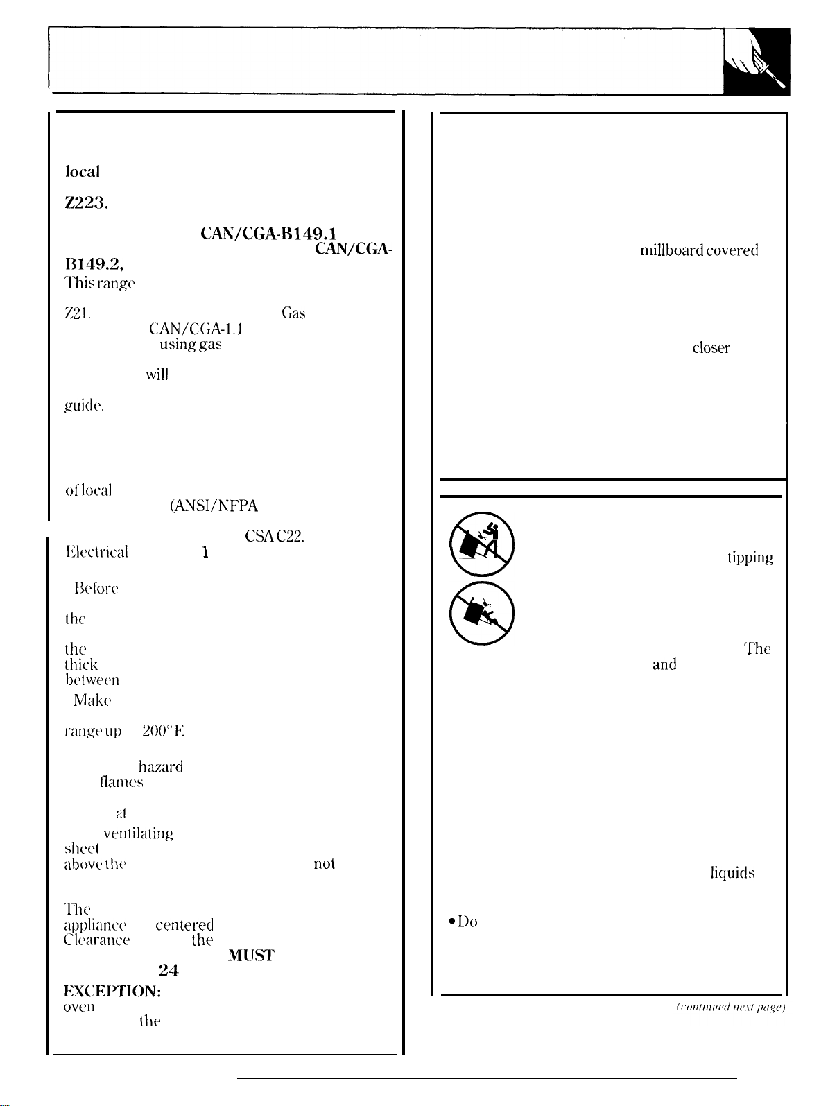
IMPORTANT SAFETY INSTRUCTIONS
Installation of this range must conform with
local codes, or in the absence of local codes,
with the National Fuel Gas Code, ANSI
Z223.
1, latest edition. In Canada, installation
must conform with the current Natural Gas
Installation Code,
current Propane Installation Code,
I114!).2, and with local codes where applicable.
‘1’his range
has been design-certified by the
American Gas Association according to ANSI
Z21.
1, latest edition and Canadian
according to CAN/C(;A-l.1 latest edition. As with
any appliance
there are certain safety precautions you should
follow. You
will
Important Safety Instructions in the front of this
guide.
Read them carefully.
●
Have your range installed by a qualified
installer or service technician.
● Your range must be electrically grounded in
accordance with local codes or, in the absence
of local
codes, in accordance with the National
Electrical Code
In Canada, electrical grounding must be in
accordance with the current
IWctrical
Code Part 1 and/or local codes. See
Electrical Connections in this section.
●
Before
installing your range on linoleum or
any other synthetic floor covering, make sure
the
floor covering can withstand 180°1? without
shrinking, warping or discoloring. Do not install
the
range over carpeting unless a sheet of 1/4”
thick
plywood or similar insulator is placed
11(’twecn
●
Mak{’
the rang-e and carpeting.
sure the wall coverings around the
range can withstand heat generated by the
I-ang(’
11])
to
200”1;”
●
Avoid placing cabinets above the range. To
reduce the
open
hazard
[Iamcw
of operating burners, install a
ventilation hood over the range that projects
forward at least 5“ beyond the front of the cabinets.
● The
vc>ntilating
she(’t
metal not less than ().0122” thick. Install
abovt> th(>
cooktop with a clearance of
than 1/4” between the hood and the underside
of the combustible material or metal cabinet.
‘1’11(’
hood must be at least as wide as the
app]ianc(>
Clt’aral~ce
and
centerc’d
between
ventilation hood surface
LESS THAN
EXCEITlON:
ov~m
or cooking appliance over the cooktop shall
conform to
24
Installation of a listed microwave
the installation instructions packed
with that appliance.
CAN/CGA-B149.l
using
,gas
and generating heat,
C,as
or the
CAN/CGA-
Association
find these precautions in the
(ANSI/NFPA 70, latest edition).
CSA C22.
1 Canadian
caused by reaching over the
hood must be constructed of
not
less
over the appliance.
the
cooking surface and the
M[JST NEVER BE
INCHES.
● If cabinets are placed above the range, allow a
minimum clearance of 30” between the cooking
surface and the bottom of unprotected cabinets.
● If a 30” clearance between cooking surface
and overhead combustible material or metal
cabinets cannot be maintained, protect the
underside of the cabinets above the cooktop with
not less than 1/4” insulating
millboard coverecl
with sheet metal not less than 0.0122” thick.
● Clearance between the cooking surface and
protected cabinets MUST NEVER BE LESS
THAN 24 INCHES. The vertical distance from
the plane of the cooking surface to the bottom of
closer
adjacent overhead cabinets extending
than
1“ to the plane of the range sides must not be
less than 18”. (See Dimensions and Clearances
illustration in this section.)
●
CAUTION:
Items of interest to children should
not be stored in cabinets above a range or on the ~ange
backsplash of a range-children climbing on the
range to reach items could be seriously injured.
WARNING
L*
@
L:
—.
@
Anti-Tip device should engage
range from tipping over.
If you pull the range out from the wall for any
reason, make sure the Anti-Tip device is engaged
when you push the range back against the wall.
● For your safety, never use your range for
warming or heating the room. Your oven and
cooktop are not designed to heat your kitchen.
Top burners should not be operated without
cookware on the grate. Such abuse could result
in fire and damage to your range and will void
your warranty.
● Do not store or use combustible materials,
gasoline or other flammable vapors and
in the vicinity of this or any other appliance.
Explosions or fires could result.
c Do
not use oven for a storage area. Items
stored in the oven can ignite.
● Do not let cooking grease or other flammable
materials accumulate in or near the range.
All ranges can tip and injury could
result. To prevent accidental
tipping
of the range, attach an approved
Anti-Tip device to the wall. (See
Installing the Anti-Tip Device in this
section.) To check if the device is
installed and engaged properly,
carefully tip the range forward.
and
prevent the
‘rhe
licluids
29

INSTALLATION INSTRUCTIONS
(continued)
GENERAL
● See Dimensions and Clearances in this section
for all rough-in and spacing dimensions. These
dimensions must be met for safe use of your range.
The location of the electrical outlet and pipe opening
(see Gas
be
Q
The range may be placed with 0“ clearance
Pipe
acijusted
and Electric Outlet Locations) may
to meet specific requirements.
(flush) at the back wall and side walls of the range,
LOCATION
I)o
not locate the range where it may be subject
to strong drafts. Any openings in the floor or wall
behind the range should be sealed. Make sure
the openings around the base of the range that
supply fresh air for combustion and ventilation
are not obstructed by carpeting or woodwork.
PROTECT YOUR FLOOR
Your range, like many other household items, is
heavy and can settle into soft floor coverings
such as cushioned vinyl or carpeting. Use care
when moving the range on this type of flooring.
It is recommended that the following simple and
inexpensive instructions be followed to protect
your floor.
The range should be installed on a sheet of plywood
(or similar material).
at the
fyont
of the
W%en
thejloor
range,
the area that the range
covering
ends
will rest on should be built up with plywood to
the same level or higher than the floor covering.
‘Ilis
will allow the range to be moved for cleaning
or servicing.
MODEL AND SERIAL NUMBER LOCATION
I)epenciing
and serial numbers on a label on the front frame
of
the
panel or broiler drawer.
on your range, you’ll
fincl
the model
range, behind the storage drawer, kick
TOOLS YOU WILL NEED
● Phillips and flat-blade screwdrivers
● Pencil and ruler
● Two pipe wrenches (one for backup)
c
l%” open-end or adjustable wrench
● Nut drivers or wrenches: 3/16” and 1/4”
ADDITIONAL MATERIALS YOU MAY NEED
●
Gas line shut-off valve
●
Pipe joint sealant or UL-approved pipe thread
tape with
Tefkm*
that resists action of natural
and LP gases
●
Flexible metal appliance connector (1/2” I. D.)
A 5-foot
length is recommended for ease
of
installation but other lengths are acceptable.
Never use an old connector when installing a
new range.
● Flare union adapter for connection to gas
supply line (3/4” or 1/2”
● Flare union adapter for connection to pressure
NIT
x 1/2” I. D.)
regulator on range (1/2” NPTx 1/2” I. D.)
*Teflon: Ikgisterecl trademark of
DoPont
PREPARATION
●
Remove all tape and packaging. Lift up the
cooktop
and remove any packing material under it. Make
sure the standard twin burners are properly
seated and level.
●
Ilemove
parts (around oven door, side trim).
● Take the accessory pack out of the oven.
● Check to be sure that no range parts have
come loose during shipping.
(on models with standard twin burners)
plastic film that covers some chrome
I
30

❑
pROvlDE ADEQUATE
GAS
WPPIV
Your range is designed to operate at a pressure
of 4“ of water column on natural gas or, if designed
for 1.1’
column. Make
with
gas
(propane or butane), lo’” of water
sure
you are supplying your range
the type of gas for which it is designed. This
range is convertible for use on natural or propane
~as,
if
you
d(~cide to use this range on a different
type
of gas, conversion adjustments must be
made by a service technician or other qualified
person before attempting to operate the range on
that gas.
For proper
operalion,
the pressure of natural gas
supplied to the regulator must be between 4“ and
13” of water column. For LP gas, the pressure
suppliecl
must be between 10” and 13” of water
column. When checking for proper operation of
the regulator, the inlet pressure must be at least
I“ greater
as
given
than the operating (manifold) pressure
above.
‘I-he
pressure regulator located
at the inlet of the range manifold must remain in
the supply line regardless of whether natural or
LP
gas is being used. A
Ilexible
metal appliance
connector used to connect the range to the gas
supply line should have an I.D. of 1/2” and be
5
feet in length for ease of installation. In Canada,
flexible connector-s must be single wall metal
connectors no longer than 6 feet in length.
Gas Pipe and Electric Outlet Locations
for
Models Equipped with
Gas
Pipe and Electric Outlet Locations for
$euled Bur~
blCONNECT
THE RANGE TO GAS
Shut off the main gas supply valve before
disconnecting the old range and leave it off until
new hook-up has been completed. Don’t forget
10
relight the pilot on other gas appliances when
you turn the gas back on.
Because hard piping restricts movement of the
range, the use of an A. G. A.-certified flexible
metal appliance connector is recommended
unless local codes require a
Never
new range. If the hard piping method is used,
LISe
an
olci
connector when installing a
hard-pipecl
connection.
you must carefully align the pipe; the range
cannot be moved after the connection is made.
‘1’o prevent gas leaks, put pipe joint compound
on, or wrap pipe thread tape with Teflon*
arouncl,
*’I’(11011: I<txist(m,d (rxl(mirk O( I)uI’011(
all male (external) pipe threads.
This area allows
for flush range
installation with
through-the-floor
connection of pipe
stubks.hut-off
(conlinud next
valve.
page)
31

INSTALLATION INSTRUCTIONS
(continued)
CONNECT THE RANGE TO GAS
(continued)
Flexible Connector Hookup for Models
Equipped with Sealed Burners
Pressure
Regulator
*4
,O.,,bow
(provided)
Installer: Inform
consumer of the
location of the gas
shut-off valve.
‘>;.
“ “
J$ti’,
Adapter
the
l/2”or
Gas Pipe
9
t
3{4”
+
8
i
iil
-
~[
“-7””4
.$
‘j
,<
.=
Flex
Connector
(6 ft. max.)
Adapter
“-l
~
Gas
Shut-off
Valve
Rigid Pipe Hookup for Models Equipped
with
Seuled..6-urne~s
Flexible Connector and Rigid Pipe Hookups for
Models Equipped with Standard Twin Burners
I
I
I
,o-,lbow+~,=,~=,
(provided)
t+
Nipple Union
!,,
~90°
.,.
n
~
~
E/
nl
Installer: Inform the
consumer of the
location of the gas
shut-off valve.
112”
or 3148’
Gas Pipe
~
?
1
b
Elbow
Black
Iron Pipe
~
Union
4——— Nipple
Gas
Shut-off
4-- Valve
32

1. Install a manual gas line shut-off valve in the
gas line in an easily accessed location outside of
the range. Make sure everyone operating the
range knows where and how to shut off the gas
supply to the range.
2. Install male 1/2” flare union adapter to the
1/2”
NIT
internal thread elbow at inlet of
regulator. On models equipped with dual
burners, install the male pipe thread end of
the 1/2” flare union adapter to the 1/2” NPT
internal thread at inlet of pressure regulator.
Use a backup wrench on the regulator fitting
to avoid damage.
When installing the range from the front,
remove the 90° elbow for easier installation.
3. Install male 1/2” or 3/4” flare union adapter
to the NPT internal thread of the manual shutoff valve, taking care to back-up the shut-off
valve to keep it from turning.
4. Connect flexible metal appliance connector
to the adapter on the range. Position range
to permit connection at the shut-off valve.
5. When all connections have been made, make
sure all range controls are in the off position and
turn on the main gas supply valve. Use a liquid
leak detector at all joints and connections to
check for leaks in the system.
CAUTION: DO NOT USE A FLAME TO
CHECK FOR GAS LEAKS.
When using test pressures greater than 1/2 psig
to pressure test the gas supply system of the
residence, disconnect the range and individual
shut-off valve from the gas supply piping. When
using test pressures of 1/2 psig or less to test the
gas supply system, simply isolate the range from
the gas supply system by closing the individual
shut-off valve.
❑
ELECTRl~L
Electrical Requirements
CONNECTIONS
(on some models)
120-volt, 60 Hertz, properly grounded branch
circuit protected by a 15-amp or 20-amp circuit
breaker or time delay fuse.
Extension Cord Cautions
Because of potential safety hazards associated
with certain
conclitions,
we strongly recommend
against the use of an extension cord. However,
if “you still elect to use an extension cord, it is
absolutely necessary that it be a
UL-listed,
3-wire grounding-type appliance extension cord
and that the current carrying rating of the cord
in
amperes
be equivalent to, or greater than,
the branch circuit rating.
Grounding
IMPORTANT-( Please read carefully)
FOR
PERSONAL SAFETY, THIS APPLIANCE
BE
MUST
PROPERLY GROUNDED.
The power cord of this appliance is equipped
with a three-prong (grounding) plug which
mates with a standard three-prong grounding
wall receptacle
PREFERRED
METHOD
QJ?
r
QVJ
@
%~
c!
%
n
Ensure proper
ground exists
before use
i
to minimize the
possibility of
electric shock
hazard from
this appliance.
The customer
should have the
wall receptacle
and circuit
checked by a
qualified electrician to make sure the receptacle
is properly grounded.
Where a standard two-prong wall receptacle is
encountered, it is the personal responsibility and
obligation of the customer to have it replaced with
a properly grounded three-prong wall receptacle.
DO NOT, UNDER ANY
CIRCUMSTlkNCES,
CUT OR REMOVE THE THIRD (GROUND)
PRONG FROM THE POWER CORD.
(Collflt!lld
11(,.rt
/)(l<y<,)
33

INSTALLATION INSTRUCTIONS
(continued)
ELECTRICAL CONNECTIONS
(continued)
❑ Usage Satiations where Appliance
Power Cord will be Disconnected Infrequently.
adapter maybe used only on a 15-amp
An
Do
circuit.
circuit. Where local codes permit, a
TEMPORARY CONNECTION may be
made to a properly grounded two-prong wall
receptacle by the use of a UL-listed adapter,
available at most hardware stores. The larger
slot in the adapter must be aligned with the
larger slot in the wall receptacle to provide
proper polarity in the connection
power cord.
TEMPORARY
METHOD
(Adapter plugs not
permitted in Canada)
CAUTION:
terminal to the wall receptacle cover screw
does not ground the appliance unless the cover
screw is metal, and not insulated, and the wall
receptacle is grounded through the house
wiring. The customer should have the circuit
checked by a qualified electrician to make sure
the receptacle is properly grounded.
[
not use an adapter on a 20-amp
of
the
q- -
fir~
Align large
prongslslots
I i{ “
@i
““ -/
‘“
Ensure proper
v
m
~1
‘
ground and
firm connection
before use
Attaching the adapter ground
❑ Usage Situations where Appliance
Power
Cord will be Disconnected Frequently.
Do not use an adapter plug in these situations
because disconnecting of the power cord
places undue strain on the adapter and leads to
eventual failure of the adapter ground terminal.
The customer should have the two-prong
wall receptacle replaced with a three-prong
(grounding) receptacle by a qualified electrician
before using the appliance.
The installation of appliances designed for
mobile home installation must conform with
the Manufactured Home Construction and
Safety Standard, Title 24 CFR, Part 3280
(formerly the Federal Standard for Mobile
Home Construction and Safety, Title 24,
H[JD,
Part 280) or, when such standard is not
applicable, the Standard for Manufactured
Home Installations, latest edition (Manufactured
be
Code.
ANSI
in
Home Sites, Communities and Set-Ups),
A225.1,
latest edition, or with local codes. In
Canada, mobile home installation must
accordance with the current
z240/MH
Mobile Home Installation
CAN/CSA
Electric Disconnect
1. Locate disconnect
plug
on the range back.
2. Pinch sides of connector and pull out of
range back.
You will have
this
disconnect plug.
When disconnecting the power cord from the
adapter, always hold the adapter with one hand.
If this is not done, the adapter ground terminal
is very likely to break with repeated use. Should
this happen, DO NOT USE the appliance until a
proper ground has again been established.
34

❑
SEAL
Seal any openings in the
and in the floor under the range when hookups
are completed.
❑
(for Models Equipped with Standing Pilots)
The range should be installed in its permanent
position before any pilots are lit or adjusted.
Light the Surface Burner Pilots
CAUTION: Make sure the surface burner
control knobs are in the OFF position before
attempting to
1. Raise the
2. Light both pilots with a match.
3. To
closing cooktop after lighting pilots.
THE OPENINGS
wall
behind the range
LIGHT
THE
PILOTS
light
the pilots.
cwoktop.
avoid pilot outage, use caution when
a
...----1
---::.;”“ -
T
:..
NOTE: Do not leave standing pilot lit in a newly
constructed or remodeled home or apartment
that will be unoccupied for more than a month.
Each pilot flame was adjusted at the factory to be
approximately 5/16” tall. A tinge of yellow
appearing at the upper tip is normal. If you find
pilot adjustment is necessary, follow instructions
at right.
‘c
‘-%%
v]
\
Adiust
the Surface Burner Pilots if Necessary
of the manifold panel.
3. To adjust, use a blade-type screwdriver with
a shaft diameter of less than 3/16”. Turn pilot
adjustment screw until pilot is 5/16” high.
not reduce the flame to less than 5/16” or pilot
outage may occur. A pilot flame burning higher
than recommended may generate soot (carbon
black) on the bottom of your cooktop.
Light the Oven Pilot
CAUTION:
knob is in the OFF position before attempting to
light the pilot.
1.
Remove the broiler drawer by sliding the
drawer all the way out and then lifting slightly to
remove it from it’s tracks.
2. Locate the pilot at the
back of the broiler
compartment. The pilot
is attached to the left
side of the oven burner.
3. Light the pilot with a
match. No adjustments ar
required for natural gas.
For LP gas, see How to
Convert the Range for
Use with LP Gas or
Natural Gas.
Make sure the OVEN CONTROL
Do
I
——
((
’[)llritlllw/
/1(,.[/
p[l,y(,)
35

INSTALLATION INSTRUCTIONS
(continued)
Light the Pilots
e
4. ‘l’urn the OVEN CONTROL” knob to a setting
above
and impinge on the temperature-response element.
The oven burner will light in 30-90 seconds.
The oven burner will operate until the set
continue to
by the OVEN CONTROL knob.
200°fZ
temperature is reached. The oven burner will
maintain the oven at the temperature indicated
❑
CHECK IGNITION OF SURFACE BURNERS
Surface Burner Ignition
operation of all
should be checked after the pilots have been
lighted (on some models) and range and gas
supply lines have been carefully checked
for leaks.
Standing Pilot Models
~elect
a top burner knob and simultaneously
push in and turn to HI position. The burner
should
burner in succession until all burners have
been checked.
Electric Ignition Models
Select a top burner knob and simultaneously
push
a snapping sound indicating proper operation
of the spark module. Once the air has been
purged from the supply lines, burners should
light within 4 seconds. After burner lights,
rotate knob out of the LITE position. Try each
burner in succession until
been checked.
light
in and turn to LITE position. You will hear
(continued)
Heater Pilot Flame
The pilot flame will increase in size
cycle
on and off as necessary to
cooktop
within a few seconds. Try each
U
and oven burners
all
burners have
Quality of Flames
The combustion quality of burner flames
to be determined visually.
(B) Yellow tips on
outer
Normal for
(C) Soft blue flames—
Normal
If burner flames look like (A),
Normal burner flames should look like (B) or
on
(C), depending
With LP gas, some
cones is normal.
❑
CHECK IGNITION OF OVEN BURNER
Your oven is designed to operate quietly and
automatically. To operate the oven, turn the OVEN
CONTROL knob to a setting above 2000”
30-90 seconds, the oven burner will ignite
burn until the set temperature is reached. The
oven burner will continue to cycle on and off as
necessary to maintain the oven
indicated by the OVEN CONTROL knob.
Electric ignition models require electrical
power to operate. The oven cannot be lit during a
power outage. Gas will not flow unless the
bar is hot.
If the oven is in use when a power
the burner will shut off and cannot
power is restored.
the type of gas you use.
yellow
tipping on outer
cones—
for natural
call
for service.
at
the temperature
outage occurs,
be
1.1’
gas
E
re-lit
needs
gas
After
ancl
glow
until
36

❑
ADJUSTING THE AIR ADJUSTMENT SHUTTER
‘1’o
determine if the bottom burner flames are
burning properly, first remove the oven bottom
and
the burner baffle.
I <P
T’
‘\&b
f
A?’%
,,,/””
/
““
\
al
*J
To remove the oven bottom:
1. Remove knurled screws holding down rear of
oven bottom.
2. Grasp oven bottom at finger slots on each side.
3.
Lift rear of oven bottom enough to clear the
lip
of range frame, then pull out.
Burner Baffle
Onsomyw’”
.,
\/’
Oven Bottom
,
Remove Screw
../-
AZ
=-
\
.
With the baffle removed, properly adjusted
flames should have approximately 1“ blue cones
and, if range is supplied with natural gas, should
burn with no yellow tipping. (With most LP gas,
small
yellow
tips at the end of outer cones are
normal.) Flames should not lift off burner ports.
If lifting is observed, gradually reduce air shutter
opening until flames are stabilized. With the
baffle in place, or with the oven bottom in place
(on models not equipped with a burner baffle),
the flames should burn steady. They should not
extend past the edges of the burner baffle (or
the oven bottom, if there is no baffle).
‘[’he
shutter for the oven burner is near the back
wall of the oven and behind the broiler drawer.
To remove the broiler drawer:
1. Pull the drawer out until it stops, then push it
back in about one inch.
2. Grasp handle, lift and pull broiler drawer out.
To remove the burner baffle (on some
models):
1. Use
head screw shown in the illustration above.
Do not remove any other screws.
2.
a nut driver to remove the 1/4” hex-
Pull baffle straight out until it is free from the
slot that holds it at rear of oven.
Remove the metal shield at the rear of the cavity.
The air adjustment shutter is behind this shield.
To adjust the flow of air to the burner, loosen the
Phillips-head screw and rotate the shutter to
allow more or less air into the burner tube.
37

9
LEVELING THE RANGE
❑
1.
Remove the storage
drawer, broiler drawer
or kick panel.
2. Use a 3/16” open-end
or
socket wrench to back
out both rear leveling
legs approximately two
turns.
1%”
3. Use a
or adjustable wrench to
back out the front
leveling legs two turns.
4. Install the oven
shelves in the oven and
position the range
where it will be installed.
5. Check for levelness by placing a spirit level or a
cup, partially filled with water, on one of the oven
racks. If using a spirit level, take two readings—with
the level placed diagonally first in one direction and
then the other.
6. Adjust the leveling legs until the range is level.
7. After the range is level, slide the range away from
the wall so that the Anti-Tip device can be installed.
❑
INSTALLING THE ANTI-TIP DEVICE
open-end
“w
2. Locate the outside
toward the center of the range from the marked
edge of the range.
3. Using the device as a template, mark the
position of the hole for the screw.
4. For wood construction, drill a pilot hole at an
angle of 20 degrees from the horizontal. A nail
awl may be used if a drill is not available.
Mount the Anti-Tip device with the screw provided.
For cement or concrete construction, you
will need a 1/4” x
sleeve anchor, which are not provided. Drill
the recommended size hole for the hardware.
Install the sleeve anchor into the drilled hole and
then install the lag bolt through the device. The
bolts must be properly tightened as recommended
for the hardware.
e~ge
of the
1X”
lag bolt and a 1/2” 0.1).
clevim 2X”
or
WARNING:
●
Range
must be secured with an approved
AntiTip
Q
tipped by you or a
leaning
●
i[
range forward.
c
recognized industry tip standards for all normal
conditions.
.
tipping of the range when not properly installed.
●
does not fit this application, use the universal
Anti-Tip device
1.
Mark the wall where the RIGHT EDGE of the
range is to be located.
countertop overhang if you intend to install the
range
device.
Unless properly installed, the range could be
child
standing, sitting or
on
an open door.
After installing the Anti-Tip device, verify that
is in place by carefully attempting to tilt the
This range has been designed to meet all
The
use of this device does not preclude
If the Anti-Tip device supplied with the range
WB02X7909.
Be
sure to allow for the
next to cabinets.
ancl
5. Slide the range against the wall,
proper installation by grasping the front edges of
the rear surface unit openings and carefully
attempting to tilt the range forward.
I WHENALLHOOKUPSARECOMPLETED:
MAKE SURE ALL
POSITION.
MAKE SURE THE FLOW OF COMBUSTION AND
VENTILATION AIR TO THE RANGE IS UNOBSTRUCTED.
CONTROLSARE
check for
I
LEFT IN THE OFF
-
38
——

HOW TO CONVERT THE RANGE FOR USE
WITH LP GAS OR NATURAL GAS
This range leaves the factory set for use with natural
g-as. If you convert to LP gas, keep these instructions
and orifices in case you want to convert back to
natural gas.
NOTE: Need to buy kit
top burners of model
WB28K0085
RGB508.
to convert the
❑
Standard Twin Burner Models
(models with lift-up cooktops)
NAT
0
Cap
+!!9
Gas Flow
nge
LP —
Cap
@
.
TOOLS REQUIRED:
T-lo
‘1’orxdriver
1/2” and
3/4”
(for sealed burners)
open-end wrench
Flat blade screwdriver (small)
Nut drivers or wrenches: 7mm, 5/16” or a small
adjustable (depending on the size of the spuds)
❑
pREpARE RANGE FOR CONVERSION
(1) Turn off gas supply at the wall.
(2) Turn off the electrical power to the range.
If range has not yet been connected to gas
supply,
or if flexible connection was made, range may be
pulled out from the wall to make conversion easier.
❑
CONVERT THE PRESSURE REGULATOR
WARNING: Do not remove the pressure
regulator from the range.
close
TO OPEN.
WN
If it is this regulator:
1. Use a coin to remove the cap from the
pressure regulator.
2. Turn the cap over and hook it into the slots.
The type of gas to be used should now be visible
on the top of the cap.
❑
Sealed Burner Models
(models without lift-up cooktops)
1. For models equipped with sealed burners,
remove the storage drawer, broiler drawer or
kick pane] and locate the pressure regulator at
rear of
thr
rang-e.
Remove Screws
Access Cover
\
/
on some models, you may have to remove an
access
]:or
burners, remove the
covc>r
also.
models equipped with standard twin
cooktop
and locate the
pressure regulator at right rear of range.
2. Fo]low
the directions in A or B that match
❑ 0
your regulator type.
—
except for conversion
If it is this regulator:
1.
Unscrew the plastic-protected hex-nut cap
from the regulator.
2. Carefully pry the protective plastic cap off
the threaded metal cap. Gently pull the plastic
washer off the threads on the other side of the
metal cap.
3. Push the plastic cap onto the end of the metal
cap displaying the type of gas you are converting
to. Press the attached plastic washer onto the
threads on the other side of the metal cap.
4. Screw the hex-nut cap back into the regulator.
Do not overtighten.
(continued next pqge)
—
39

CONVERTING TO LP GAS
(continued)
HOW TO CONVERT THE RANGE FOR USE
GAS
WITH 1P GAS OR NATURAL
❑
CONVERTING
MODELS EQUIPPED WITH SEALED BURNERS
(See Step 4 if range is equipped with standard
twin burners.)
Burner Cap
1. Remove the grates, burner caps and
burner heads.
2. Using the torxdriver,
by unscrewing the
Lift the burner straight out.
DO NOT disconnect the wires from the burner
bases unless the
3.
Remove the brass orifice spud
burner base by unscrewing spud from fitting with
7
mm or small adjustable wrench (depending on
the size of your spuds). Apply a 3/4” wrench to
the hex on the gas inlet
when removing spud to prevent the
aluminum tube from twisting.
4. Install orifice spuds
following diagrams (see ❑ or B ), for
or natural gas, depending on which you are
SURFACE
3
small screws in each base.
cooktop needs to be raised.
BURNERS
remove
tube
accordin
(continued)
ON
the burner bases
uncler
each
as a back-up
to one of the
1,1’
d
gas
❑
Orifice Spuds for
LP orifice spuds are in a small plastic bag packed
with this Use and Care Guide. LP orifice spuds
have a 2-digit number and the letter “L” on one
side. Each orifice spud will also have 1 or
grooves on one side, denoting the location on the
range where it is to be installed as shown below.
W.n.f.am
❑
Orifice Spuds for Converting to
Natural gas orifice spuds have a 3-digit number
on one side. Each orifice spud will also have 1,
2
or 3 grooves on one side, with the letter “N”
underneath denoting the location on the range
where it is to be installed as shown below.
ii?
N
●
●
u
Convetiingto uGas:
●
&vii/J
F
--
2
Uatural Gas:
II
N
40

5. To prevent leakage, make sure the orifice
spuds are securely screwed into the gas inlet
tubes. Use a small wrench to hold the inlet tube
hex to prevent it from twisting.
6. Put old orifice spuds back in the bag to save
for possible future conversion.
NOTE: If an oritice spud is accidentall
droppecl,
the cooktop
y
can be raised by
the 2 front clips
with a large flat
‘disengaging
blade screwdriver.
e“
DO NOT attempt to raise the cooktop without
removing
4 burner
bases.
al]
If wires were disconnected to remove the
cooktop, feed wires through the burner holes in
the cooktop. Attach to each burner electrode
terminal carefully, making sure not to bend the
terminal. Then lower cooktop until it snaps
over the clips.
Electrode
Tall Screw
7. Carefully insert burner bases straight down
with the tube over the orifice spud. Replace the
screws,
opposite the
burner base.
making
b“urner
sure the tall screw is
electrode in each
❑
CONVERTING SURFACE BURNERS ON
MODELS EQUIPPED
BURNERS (See
Step 3 if range is equipped with
WITH STANDARD TWIN
sealed burners.)
1.
Lift cooktop.
2. Lift burner assemblies straight up and set
aside to
access to
gain
/
\
surface burner
spuds.
3. With a
5/16”
or small
adjustable
wrench, remove
each of the four
spuds on the
surface burner
gas inlet tubes
re~lace
and
them with the
p
.,.
correct gas spuds mounted in a holder at the
right rear of the range, above the regulator.
Natural gas spuds are brass and LP gas spuds
are red
or silver. (Mount the spuds that you
removed from the inlet tubes back in the
holder.) To prevent leakage, make sure spuds
are securely screwed into gas inlet tubes.
4. Replace the burner assemblies.
5.
Keep all spuds with your range so you have
them if you move or get a different gas hook-up,
Top Burner
Natural Gas
LP (Propane)
Orifice
#54 (.0550 Dia.)
+%6
Drill Size
(.0330 Dia.)
Color
Brass
Red or Silver
(co)iiimwd
ne.ri pu,ge)
41

@
CONVERT OVEN THERMOSTAT
(for Models Equipped with Standing Pilots)
1. Remove
2. Locate the gas selector
screw at left of thermostat
shaft. Turn the screw until
the small pointer stops at
LP or N, depending on the “
type of
converting to. The most the
screw will move is 1/2 a turn.
3. Replace the
CONTROL
❑
CONVERT THE
Oven
1.
drawer, oven bottom and burner baffle (on some
models). The lower burner orifice spud is
located behind the storage drawer, broiler
drawer or kick panel. (on some models, a metal
shield must be removed to access the orifice.)
2. To convert to LP gas,
use a 1/2” wrench to turn
the lower burner orifice
spud clockwise. Tighten the
spud only until it is snug.
To prevent damage, do
not
To convert to natural gas,
loosen the spud about 2 turns.
Burner
Remove oven door, storage drawer or broiler
overtighten the spud.
the
OVEN CONTROL knob.
gas you are
OVEN
kno~. ‘--
@
OVEN BURNER
““
ti
(,4
-
J
ORIFICES
~
CONVERT A
Screw
Aw
Shutter
the edges of the burner baffle. After 30 seconds
of burner operation, check for flames liftin
burner ports. If lifting is observed,
reduce air shutter opening until flames are
stabilized.
For natural gas, the shutter should be open
1/2”
or
about 3/4 of the way open.
~
CHECK FOR LEAKS
When all connections have been made, make sure
all range controls are in the off position and turn
on the main
detector at all joints and connections to
leaks in the system.
CAUT ION: DO NOT USE A FLAME TO
CHECK FOR GAS LEAKs.
When using test pressures greater than 1/2
to pressure test the
residence, disconnect the range and individual
shut-off valve from the gas suppl
using test pressures of 1/2
gas supply system, simply isolate the range from
the gas supply system by closing
shut-off
valve.
IR ADJUSTMENT
For LP gas, loosen the
Phillips head screw and
rotate the shutter to the
full open position. With
baffle in place, flames
should have approximately
l-inch blue cones and
should not extend beyond
gas supply valve. Use a liquid leak
gas
supply system of the
psig
SHUTTER(S)
.
.
gradua]]y
piping. When
y
or less to
the individua]
off
g
check for
psig
test
the
42
———.——
.——.—
.———.—
.—-——.

❑
CONVERT
NOTE: Only valves
with these types of
knobs are adjustable.
TOP BURNER VALVES
OFF ~,>
I*
m
s?
-~
~
‘w
1.
Turn all top burners to LOW.
2. Remove a]] fourknobs. ‘..
3.
With a small flat blade
screwdriver, turn the
valve set screws
clockwise to clecrease flame
size, counterclockwise to increase
flame size. Adjust until the flame is
about. the same height as the top
of the burner.
4. Replace the knobs.
5. Check for flame outage by opening and
closing the oven door several times. If the flame
goes out, increase the flame size.
W+.
q
\
““?’
.x
“\\
‘,
‘r
\ i
//
)(
❑
CHECK QUALITY OF FLAMES
The combustion quality of burner flames needs
to be determined visually.
m“’’’’’’’”’”
(B) Yellow tips on
outer
Normal for LP gas
(C) Soft blue flames-
Normal for natural gas
If burner flames look like (A), call for service.
Normal burner flames should look like (B) or
(C), depending on the type of gas you use.
With LP gas, some yellow tipping on outer
cones is normal.
cones—
I
❑
ADJUST THE SURFACE BURNER PILOTS
(for Models Equipped with Standing Pilots)
of the manifold panel.
3. To adjust, use a blade-type screwdriver with
a shaft diameter of less than
adjustment screw until pilot is 5/16” high.
not
reduce
outage may occur. A pilot flame burning higher
than recommended may generate
black) on the bottom of your
the flame to less than 5/16” or pilot
3/16”. “1’urn
soot
(carbon
cooktop.
pilot
Do
43

QUESTIONS?
USE THIS PROBLEM SOLVER
PROBLEM
OVEN WILL NOT WORK
TOP BURNERS DO NOT
LIGHT OR DO NOT
BURN EVENLY
BURNERS HAVE YELLOW
OR YELLOW-TIPPED
FLAMES
POSSIBLE CAUSE
● Plug on
●
Pilot(s)
for
● The circuit breaker in your
●
Oven
● Make sure electrical
●
Burner holes on the side or
the range
is
(are)
Standing Pilot
is not completely inserted in the electrical outlet.
not lit (on
Modeis
controls not properly set,
p] ug
standing
pilot models). See the Lighting Instructions
section in Using Your Oven.
h(}llse has
is p]
wound
been tripped, or a fuse has been blown.
ugged
into a Ii ve power outlet.
the top of burner
burners (on models with standard twin burners) or burner
with sealed burners) or burner
with
a
sewing needle or twist tie. Make sure you do not enlarge the holes. On
spill-proof models,
● Pilot(s) is (are) not
for
Standing
(A) Yellow
Gill for
●
If
burncl” tlames
I
ike (B) or (C), depending on
● With LP
flames—
service
gus, some
check
1 it
(on standing
Pilot Models
look 1 ikc (A), call for service. Norma] burner
yellow tipping on outer cones is normal.
caps
on spill-proof models, and clean them
electrode area for burned-on food or grease.
pilot
models). See the Lighting Instructions
section in Surface Cooking.
(B) Yellow tips
cones—Normal
the
type of
on
outer (C) Soft blue flames—
for LP
gas
gas
you use.
may be clogged. Remove
heads
(on models
Normal for natural
flames should
gas
look
BURNER FLAMES VERY
LARGE OR YELLOW
CLOCK
DOES NOT WORK
OVEN LIGHT DOES NOT
COME ON
STRONG ODOR
OVEN TEMPERATURE
TOO HOT OR TOO COLD
●
[f
range is connected to LP
●
Range
electrical pi ug must bc securely seated in a 1 ive power outlet.
gas,
check
all
steps in the Installation Instructions.
Check
blown fuse or tripped circuit breaker.
● Bulb may
● Electrical plug must be
●
1 mproper
● An odor from the insulation around the oven liner is normal for the first few
times
● The OVEN CONTROL knob
Oven
be 100SC
or burned out.
p]ugged
air/gas ratio in
oven
is used. This is temporary.
Thernmstat-D{~
oven, Adjust oven
(t
H~t~r.\c(f’section.
into a ] ive power
outlet.
burner air shutter.
needs
adjustment. See the Adjust the
for
44
—

PROBLEM
POSSIBLE
CAUSF;
SURFACE BURNERS
LIGHT BUT OVEN
DOES NOT
FOOD DOES
NOT
BROIL PROPERLY
● The oven
gas
shut
oft’ valve Inay have
accidentally
cleaning or moving.
To
check the oven
the
cooktop and
To check the oven
the storage
off lever
remove
●
Oven controls
● Oven door and/or broi
● Improper
● Food is being
● Cookware is not su
● Aluminum
and
● Oven bottom not securely seated in position.
at [he
an
access cover
shelf’
foi I
slit as recommended.
gas
shut off valve cm standard twin burner models, raise
look for the
gas
shut
druwer.
broiler drawer or kick panel and look for the
back of
the
range. On some models you may have to
also.
nol
properly
Icr
drawer
set.
position being
cooked
on L] hot
itcd for
broiling.
used on the broi
gas
shut
off
lever at the extreme right rear corner.
off’
valve on sealed burner models, remove
Sealed Burner Models
See
the Broi I
not
closed.
useci.
See the Broi 1
pun.
Ier pan
rack hm not been fitted properly
ing
section.
been
moved during
1~
ing
section.
gas
shut
FOOD DOES NOT ROAST
OR BAKE PROPERLY
If’ you need more help.. call, toll free:
GE Answer Center(”
)
● Oven controls not properly set.
● Shelf position is
● Incorrect cookware or cookware of improper
●
Oven
Do
It
●
Aluminum
●
Oven bottom not securely
800.626.2000
consumer information service
not
correct.
thermostat
needs
adjustment.
Hjllt”,~~’(t’section.
foi 1
used i
mpropcrl
Scc the Btiking
y in the oven.
seuted
i n position.
or Roasting section.
size
is being used.
Sce
the Adjust the Oven
Thermostat-
45

NOTES
46
—.———
—.. ——.—

Wdll
,“.
..-
, .,, .,.. N
With
need
Be There
the
purchase
information or assistance, we’ll be
ofyour
new Hotpoint appliance, receive the assurance that if you ever
there.
All you have to do is call—toll-free!
In-Home
Re~ak
Service
8W-GEXARES(80LM32-2737)
OtlIcoIIsIIlllc’l-”
]f{)Ilx)iIII ;Ii)p]ian(e,
(lf)rlslll]lc’lSellri(e
t
(
)nlorr(m’, or at yollr cx)nven ience
[t) 2:()() p.111.
i
nsid(>
:Ind
sel~:icc:
siilllrd~t}>s).
()(11—s()
[)l-ofkssiorl:~lwill”
scheduled at a (ire{> [h:/ [’s c(mvenienl
(olnl);lny-operatc([”
Inos( repairs can be
pr(nide expert repairservicc
Ioc:tliorlsoflklyou
(7:()() a.
our’
f;ictoI-)J-l.I’:{il~cc] t.cchnicians know
In.
handld
to
in just
7:()()
GEAnswer Center@
800626.2000
\$’ha(twer
( knit’r
(]IICSI i(
[ illle.
‘Y.
(n
-.-:.
..1
&
...,
,”. ,,..,.”,.” s,..,.,.”., . . . . . .
s,..
L
your (Iuestion about any H()(p()in{ major applian(.c,
@
infi)rnla[ion service is available to help: Your
)11— will he answered
(
;El Answer
=+
q.:;:
/!! q
J,=
5frgLo.N.....s
.,,””, ,, .,,,, ., ..,,....., .“ ...,, ,..
(
k~nter-@ sem’ice
-;
““:-r
jay::’
I
““-’!~::c...
,,
:N,
NO., ,J,,m,
.
,,.
. . . . .
,
!.
pronlpl
Iy
an(l coLlrleously.” .An(l
is open 24 hours a day, 7 days
For Customers With Special Needs...
8011621i2000
[,Ip~)ll
I~f~UL.SI,
Braille
Holpoint
br(xhure
harrier-free
wit h I imit.cd
lhcsc
800.626.2000.
mnlrols
items, f’iu’
wt.
will
Pr(widc’
for a
Yariely of”
applian(es,
to
assist
ki(cllcll
nlobilil). ‘lo ( )})t;~in
and
in plarlnillg
Ii)r persons
of” ChaI-~C,
a
(all
stmice todayor”
p.
n).
weekdap, 9:()()
onc visit.
call-and
A
on
yoLIr
fbryou.
yoLIr
yoLl
(;E
Armver
yoLIr
can (’all
a
week.
,Manv(;E
a.m.
appliance
an}’
.
(k)nsulnels
access k) a TDI) ( )r a
call
800-’1’DD-(;E.4(” :
i
nf’ornlalioll”
with impilircd hearing or
01
con~’c.nt
(N)()-W3-4:322)
sc’rvi(c’.
specc%
ional
tclc~(ypewriler nlay
I() r-quest
who
IIave
Semice
Contracts
80@626-2224
Y(
)11 t;IIl
;I1’t{>l
yoltt
a Ill (I
lI;I\[> (Ilt> SC’(IIIC Iktliny
U)(II 1
I t i
Iolpoillt” pr(dllct
i+:ImItl 1} i.s .s1
lJIc.-}L>:II L( JII
ill in
t
ract,
IIlat
(;1+;
(k)rlsunler Service will
warrantv expires, I’llrchase a
c>f’f’t>(l
and
yf~tl’11
receive a
you
‘re :tssurd of”
f’utnre
substarr tial
service
Parts andAccessories
80&626-2002
Individuals qualified to service their own appliances
hav{, IICX{IC,(I
11
OIIIC.
(
;cl]uillc Rcntw\:tl
\’1S.1,
]xirls or accessoric.s
our
Imr[s systcrn
Parts
ML~sIc
I-(
2UCI :mcl
SC*I1I
direclly {0 tht:ir
pr(wi{les
...and all are flllly
Discover cards are accepted.
;I(CCSS (()
warranted,
(wer 47,()()()
at
can
(;E u)nlract
l(d:iy
s(ill
be
[Ilc]-e
while
discount. Will]
’s prices,
User maintenance instructions contained in this booklet
cover
procedures intended to be performed
Other servicing generally should be referred to qualified
service
personneL
improper servicing may cause unsafe operation.
Caution must be exercised, since
by any user.
—

YOUR HOTPOINT GAS RANGE
WARRANTY
Staple sales slip or
cancelled
check
here. Proof of original purchase date
k
needed to obtain service
under warranty.
WHAT IS COVERED
II
I
WHAT IS NOT COVERED
FULL ONE-YEAR WARRANTY
For one year from date of original
purchase, we will provide, free of
charge, parts and service labor
home to repair or replace
your
any
part of
because of a manufacturing defect.
● Service trips to your home to
teach you how to use the product.
Read your Use and Care material.
If you then have any questions
about operating the product,
please contact vour dealer or our
Consumer
address below, or call, toll free:
GE Answer
800.626.2000
consumer information service
● Improper installation.
If you have an installation problem,
contact your dealer or installer.
You are ‘responsible for providing
the range that fails
Affai’rs
office at the
Center@
in
This warranty is extended to the
original purchaser and any succeeding
owner for products purchased for
ordinary home use in the 48 mainland
states, Hawaii and Washington,
In Alaska the warranty is the same
except that it is LIMITED because you
must pay to ship the product to the
service shop or for the service
technician’s travel costs to your home.
All warranty service will be provided
by our Factory Service Centers or by
our authorized Customer
servicers during normal working hours,
Should your appliance need service,
during the warranty period or beyond,
call 800-GE-CARES (800-432-2737).
In Canada consult your telephone
directory for the Cameo Service Center.
adequate electrical, gas, exhausting
and other connecting facilities as
described in the Installation Instructions
provided with the product.
● Replacement of house fuses or
resettinq
● Failure of the product if it is used
for other than its intended purpose
or used commercially.
● Damage to product caused by
accident, fire, floods or acts of God.
WARRANTOR IS
FOR CONSEQUENTIAL DAMAGES.
of circuit breakers.
IVOTRESPC)NSIBLE
D.C.
Care”
I
Some states do not allow the exclusion or limitation of incidental or consequential damages, so the above limitation or exclusion
may not apply to you. This
To know what your legal
This book is printed on recycled paper.
Part No, 164
Pub No. 39-4738
7.94
D2764P1345
{
CG
,warranty
rights
Manager—Consumer Affairs, GE Appliances, Louisville, KY 40225
gives you specific legal rights, and you may also have other rights which vary from state to state.
are in your state, consult your local or state consumer affairs office or your state’s Attorney General.
If further help is needed concerning this warranty, write:
Warrantor: General Electric Company
ttcYIPolNT
Printed in Louisville, KY
RGB508
RGB524
RGB525
RGB526
RGB527
RGB528
I
I
RGB532
RGB533
RGB535
RGB6”
RGB6,
 Loading...