

Page 1
GE Consumer & Industrial
TB 01-06
20-in. and 24-in.
Training Bulletin
January 2006
Compact Gas Range
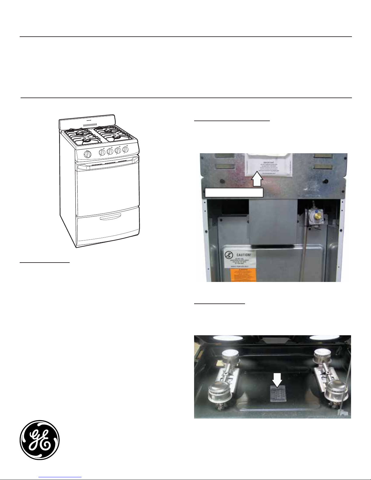
Model Introduction
TECHNICAL DATA SHEET
The technical data sheet is located on the back of
the range, near the top.
Technical Data Sheet
INTRODUCTION
GE is producing new 20-in. and 24-in. Compact
Gas Ranges, which are available with a standing
pilot or electronic ignition. They also come
standard with 2 oven racks, recessed lift-up
cooktop, separate lower broiler drawer and
removable oven door. The 4 top burners are rated
at 9,100 BTU (natural gas) and 8,000 BTU (LP).
The oven is rated at 13,000 BTU (natural gas) and
13,000 BTU (LP).
Models:
RGA720EK - 20-in. Electronic Ignition
RGA720PK - 20-in. Standing Pilot
RGA724EK - 24-in. Electronic Ignition
RGA724PK - 24-in. Standing Pilot
GE Appliances
General Electric Company
Louisville, Kentucky 40225
SERIAL NUMBER
The model/serial tag is located under the cooktop,
on top of the burner box.
GE CONFIDENTIAL AND PROPRIETARY INFORMATION – NOT FOR PUBLIC DISCLOSURE
Page 2
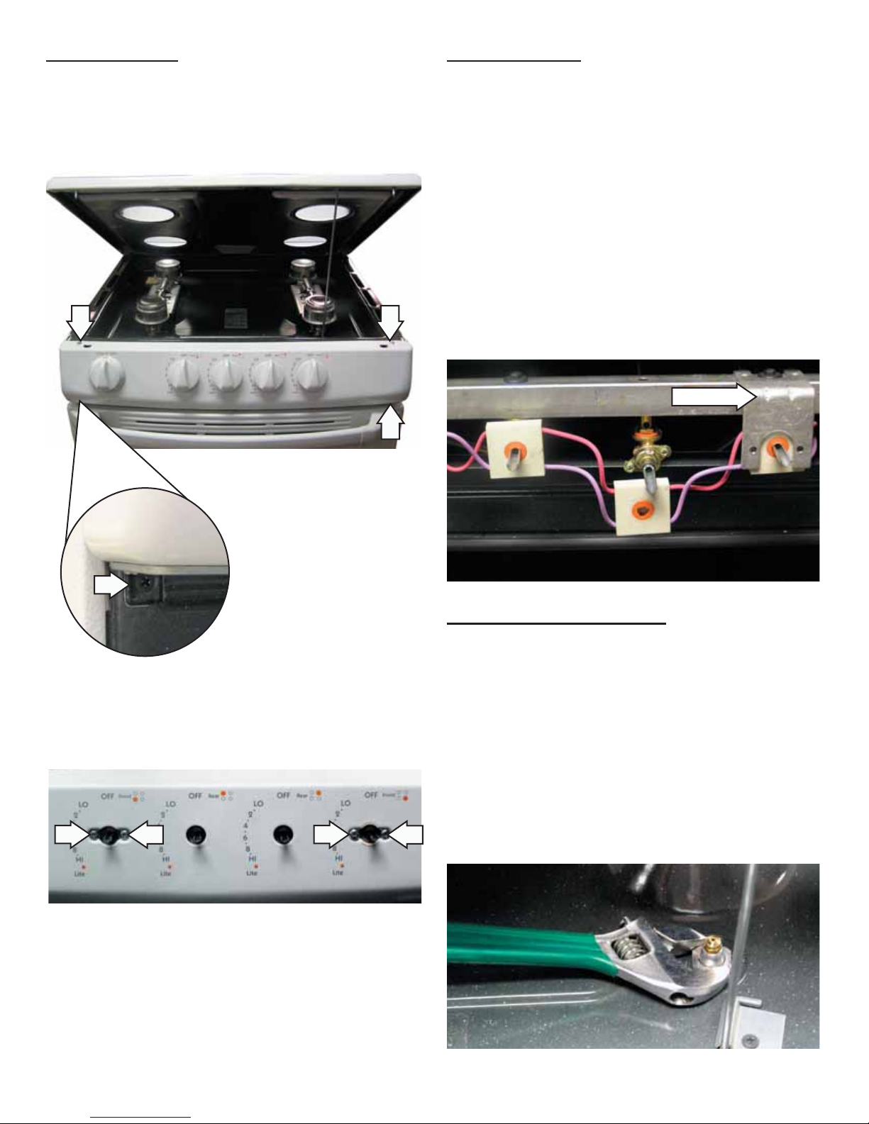
MANIFOLD PANEL
SWITCH REMOVAL
There are 8 screws that hold the manifold panel in
place.
4 Screws (Top and Bottom of the Manifold Panel)
1. Prop open the cooktop.
2. Remove the gas control knobs, then remove the
manifold panel.
3. To remove the switch, rotate the switch 15-20
degrees counterclockwise and pull the switch off
the manifold.
Note:
For switches located behind the bracket, the
•
valve must fi rst be removed from the manifold.
All 4 switches come as an assembly.
•
Bracket
4 Screws (Behind the Gas Control Knobs)
TOP BURNER VALVE REMOVAL
1. Remove the switch from the valve. (See Switch
Removal.)
2. For the desired valve, remove the 1/4-in. hexhead screw on the manifold.
3. Lift burners off the orifi ces, then locate the
orifi ce that corresponds to the desired valve.
4. Remove the 3/4-in. hex nut holding the orifi ce
and tube assembly as shown.
– 2 –
Page 3

5. Push orifi ce down through burner box and
remove the tube assembly from the range.
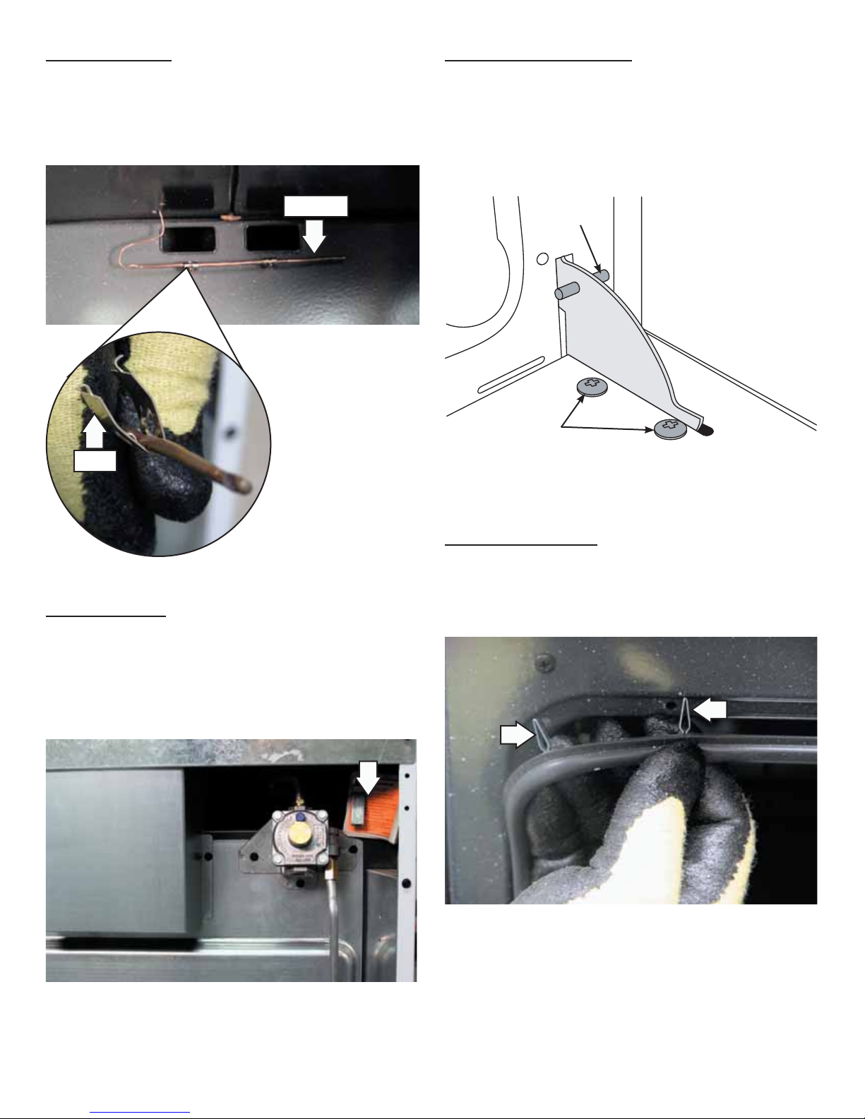
SPARK ELECTRODES
The range has 2 spark electrodes. They have
different part numbers due to wire length. The wires
are held in a retaining clip below the burner box.
The burner box must be removed to route the wires
correctly when replacing an electrode.
Spark Electrodes
When replacing the spark electrodes, tie a string to
the spark electrode wire as shown. From the top of
the range, pull the spark electrode wire up through
the range. Use the string to pull the new spark
electrode wire back through the range.
6. Use a 1/2-in. wrench to remove the valve from
the gas line.
SPARK MODULE
The spark module is located on the back of the
oven, near the bottom. It is protected by a metal
housing. The spark module is mounted with two
tabs, which snap into corresponding slots. To
remove the module, use a flat blade screwdriver to
bend the tabs toward the module body and release
the tab from the slot.
Spark Module
Spark Electrode Wire
String
Housing
– 3 –
Page 4
OVEN CAPILLARY
BROILER DOOR REMOVAL
The oven capillary is held in by 2 clips. To remove
the capillary, squeeze both clips at the same time
and gently pull the capillary away from the oven
wall.
Capillary
Clip
Open the broiler door and insert a pin into each
door hinge as shown. Remove the 2 Phillips head
screws from each hinge. Slide the drawer off the
hinges.
Pin
Screws
LP CONVERSION
The LP orifi ces are located in a small pack on the
back of the oven next to the gas regulator. Use a
1
/2-in. open end wrench to install the orifi ces. Turn
the orifi ce clockwise until snug.
OVEN DOOR GASKET
The oven door gasket is held in place by spring
clips. To remove it, place a fi nger under the gasket
beside each clip and gently pull straight out.
– 4 –
Page 5

Wiring Diagram
– 5 –
Page 6
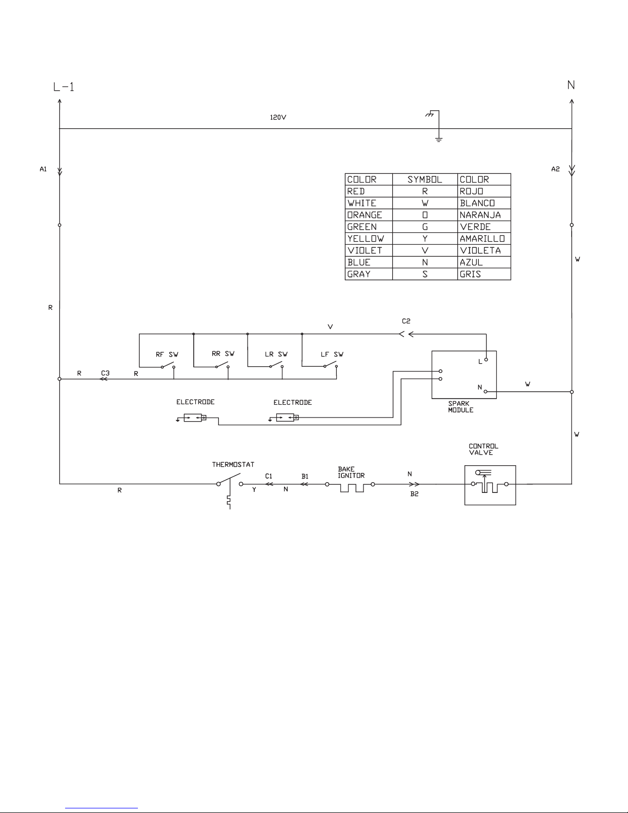
Schematic
– 6 –
 Loading...