

Page 1
GE
Grid Solutions
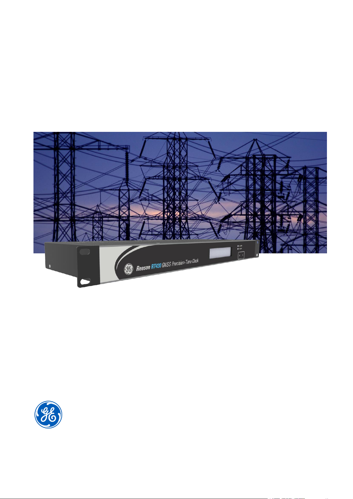
Reason RT430/RT434
GNSS Precision-Time Clock
Technical Manual
Platform Hardware Version: B
Platform Software Version: 08
Publication Reference: RT430-RT434-GNSS-TM-EN-HWB-8v1
imagination at work
Page 2

Page 3

Contents
Table of Figures 7
List of Tables 9
Chapter 1: Introduction 11
1 Foreword 11
Target Audience 11
Accronyms and abbreviations 11
2 Product Scope 13
3 Available Models 13
4 Key Features 14
GNSS 15
PTP / SNTP / NTP 15
Parallel Redundancy Protocol (PRP) 15
Stationary Mode 15
Time Sync Flexibility 16
Environmental Robustness 16
5 Functional Overview 17
6 Standards Compliance 17
Chapter 2: Safety Information 18
1 Health and Safety 18
2 Symbols 18
3 Installation, Commissioning and Servicing 19
Lifting Hazards 19
Electrical Hazards 19
Fusing Requirements 21
Equipment Connections 21
Pre-energization Checklist 22
Peripheral Circuitry 23
Upgrading/Servicing 23
4 Decommissioning and Disposal 23
Chapter 3: Hardware Design 24
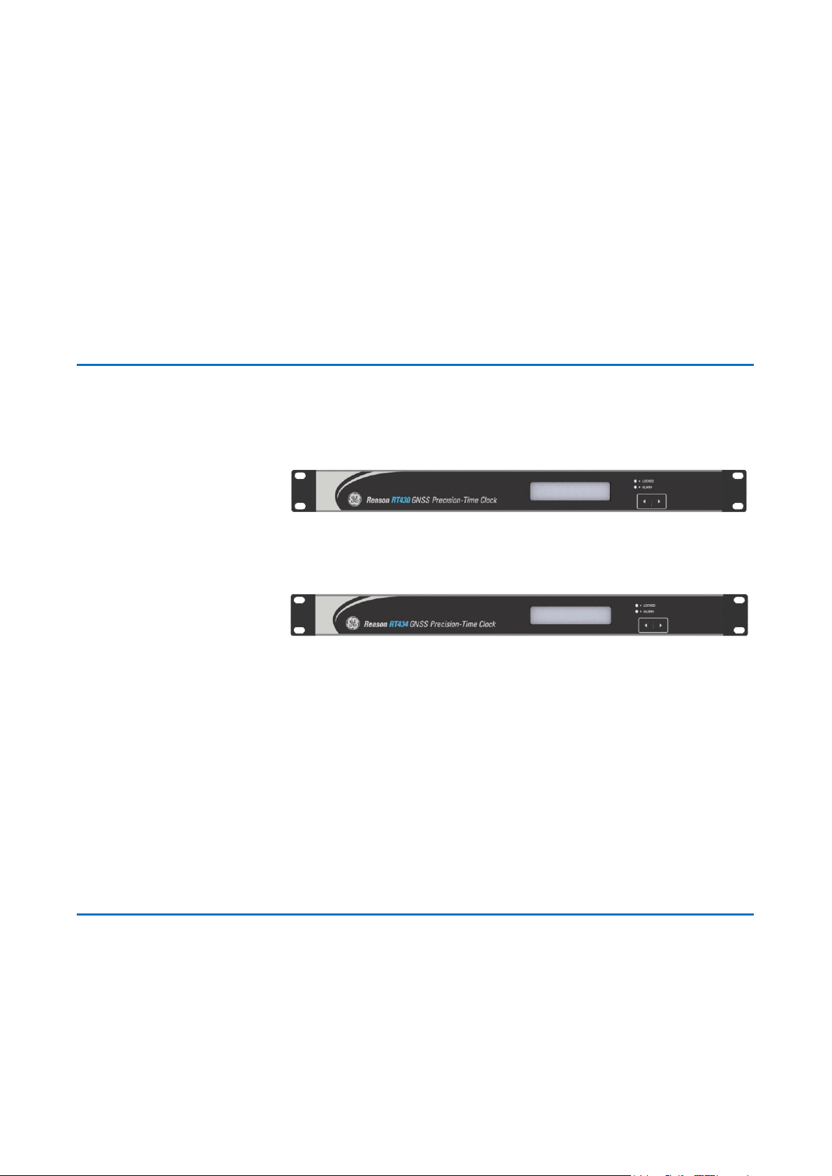
1 Front View 24
2 Rear View 24
3 Network Ports 25
4 Power Supply 25
Chapter 4: Installation 26
1 Unpacking 26
Normal Use of the Equipment 26
External Indications 26
2 Mounting 27
Power Supply 27
Grounding (Earthing) 28
Page 4

GNSS Antenna Terminal 28
TTL Electrical Outputs 30
Open-Collector Electrical Outputs 30
Optical Outputs 31
Amplitude Modulated Output 32
Serial Port (RS232, RS422/485) 32
Dry-Contact Relay 33
Event Input 33
Euro Type Connections 34
3 Ethernet Communication 34
Factory default settings 35
Network port and communication protocols 36
Equipment access 36
4 Powering Up 36
5 Preventive Maintenance Actions 37
Preventive Actions 37
Chapter 5: Operation 40
1 Local Interface (HMI) 40
2 Web Interface (Remote Access) 41
Web Interface Language 41
3 Monitoring Menus – Web Interface 42
Status 42
General Information 43
Event Log 43
Chapter 6: Configuration 45
1 Web Interface 45
User Name and Password 45
Sending Configuration 45
2 Ethernet 46
PRP (only in RT430) 46
Ethernet Ports 47
Default Gateway 47
DNS Server 47
Ethernet - Configuration Summary 47
3 Time Settings 48
Time Parameters 48
Time Settings - Configuration Summary 49
4 Time Signals 50
Outputs 50
Serial datagram 51
Customizable datagrams 52
Time Signals - Configuration Summary 53
5 PTP Configuration 55
Profile 55
Comparison between PTP Power Profiles 57
Domain number 57
Page 5

Network protocol 57
Operation mode 57
Delay mechanism 58
Grandmaster Priority 58
PTP Messages 58
PTP - Configuration Summary 58
6 Setup 60
Configuration Management 61
Password configuration 61
Reset Satellites Almanac 61
Stationary Mode 61
Demo mode 61
Log Files 62
Reboot System 62
Chapter 7: Maintenance 63
1 Time Synchronization Failure (Locked Signaling) 63
Locked indicator (HMI) 63
Remote monitoring (Web Interface) 64
Dry-contact relay (Locked) 64
IRIG-B Signal 64
PTP Protocol 64
NTP Protocol 64
SNTP Protocol 64
2 Firmware Update 64
3 Equipment Upgrade - Key Change 65
4 Cleaning Instructions 66
5 Equipment Return 66
Chapter 8: Technical Specification 67
1 Power Supply 67
2 GNSS Antenna 67
GNSS Antenna Receiver 67
GNSS Antenna Type 68
Antenna Cable 68
Surge Arrester 69
3 Internal Oscillator 69
4 Outputs 70
Connectors 70
TTL Electrical Outputs 71
Open Collector Electrical Outputs 71
Optical Outputs 72
Amplitude Modulated Output 72
Serial Port (RS232, RS422/485) 73
5 Dry-contact Relay 73
6 Event Input 73
7 Precision Time Protocol PTP (IEEE 1588) 74
8 Ethernet Ports 74
Page 6

9 Environment 75
10 Type Test 75
11 Dimensions, Weight 78
Chapter 9: Ordering Options 79
1 RT430 GNSS Cortec 80
2 RT434 GNSS Cortec 81
Chapter 10: Appendixes 83
Appendix A – IRIG-B Standard Summary 83
Appendix B – PTP Standard Concepts (IEEE1588) 88
Description 88
Definitions according to IEEE 1588 Standard 88
Hierarchical Topology 89
Multicast and Unicast Networks 89
PTP Synchronization 90
Network protocols 91
Clock operation mode 91
Delay measurement mechanism 91
Master, Slave and Grandmaster clocks 92
PTP Messages 92
Appendix C – Serial Datagrams 93
ACEB Datagrams 93
NEMEA GPZDA Datagram 93
Meinberg Datagram 94
Appendix D – Antenna Delay Compensation 96
Signal Attenuation 96
Propagation Delay 96
Appendix E – Application Examples 98
Application Example 1: Traditional and Modern Time Sync 98
Application Example 2: System Wide Grandmaster Clock 98
Application Example 3: Synchrophasor, TWFL and Process Bus Applications 99
Application Example 4: IEEE 1588 in a PRP Network 100
Application Example 5: Time Sync Expansion using RT411 and RT412 101
Page 7

Table of Figures
Figure 1: Functional Overview of RT430/434 17
Figure 2: Front view of RT430 24
Figure 3: Front view of RT434 24
Figure 4: Rear view of RT430 25
Figure 5: Rear view of RT434 25
Figure 6: Location of Serial number, part number and outputs description. 26
Figure 7: Pre-insulated tubular pin terminals 27
Figure 8: Supply connector assembly 27
Figure 9: RT430/RT434 Power Connection 27
Figure 10: RT430/434 Grounding Strap 28
Figure 11: GNSS antenna connector 28
Figure 12: Recommended position for installing the GNSS Antenna 29
Figure 13: Recommended position GNSS Antenna conduit installation 29
Figure 14: TTL electrical outputs 30
Figure 15: Open collector electrical outputs 31
Figure 16: Connection diagram of the open-collector electrical outputs 31
Figure 17: Optical outputs 32
Figure 18: Amplitude modulated output 32
Figure 19: Serial port RS232 and RS422/485 32
Figure 20: Dry-contact relay 33
Figure 21: Event input 34
Figure 22: Euro Type label for connections 34
Figure 23: Electrical communication interface via Ethernet network 35
Figure 24: Local Interface from RT430 and RT434 40
Figure 25: Navigating the RT430’s local monitoring display 40
Figure 26: RT430 Web Interface 41
Figure 27: Languages available in the Web Interface 41
Figure 28: Section to monitor the status of the unit in the Web Interface 42
Figure 29: Section to visualize general information of the system 43
Figure 30: Section of Web Interface to monitor timestamps of event input 44
Figure 31: Section to configure network parameters of the unit 46
Figure 32: Enabling the PRP redundancy 47
Figure 33: Section to configure time parameters 48
Figure 34: Section to configure time signals applied in the outputs 50
Page 8

Figure 35: Section to configure PTP parameters 55
Figure 36: Characteristics from PTP Power Profile IEEE C37.238:2011 56
Figure 37: Characteristics from PTP Power Profile IEEE C37.238:2011 56
Figure 38: Setup section in Web Interface 60
Figure 39: Manual Time setting – only available in Demo Mode 62
Figure 40: Section to update firmware 65
Figure 41: Section to equipment upgrade – key change 65
Figure 42: Rear panel connectors of RT430 (top) and RT434 (bottom) 70
Figure 43: RT430/434 Dimensions 78
Figure 44: Traditional x Modern Time Synchronization 98
Figure 45: System Wide Grandmaster Clock 99
Figure 46: Synchrophasor devices synced by RT430/434 99
Figure 47: TWFL application using RT430/434 for Time Sync 100
Figure 48: Process Bus application using PTP via the Station Bus network. 100
Figure 49: Process Bus application using PTP via the Station Bus network. 101
Figure 50: Time Sync expansion using RT411 and RT412 101
Page 9

List of Tables
Table 1: Serial port pinout 32
Table 2: Ethernet port 1 default settings 35
Table 3: Ethernet port 2 default settings 35
Table 4: Ethernet port 3 default settings (RT434) 35
Table 5: Ethernet port 4 default settings (RT434) 35
Table 6: Gateway and DNS Server default settings 36
Table 7: Gateway and DNS Server 36
Table 8: Factory default username and password 45
Table 9: Summary of configurable network parameters 48
Table 10: Summary of configurable time parameters 49
Table 11: Customizable datagram special characters 52
Table 12: Summary of all configurable parameters for outputs 53
Table 13: Comparison between PTP Power Profiles 57
Table 14: Summary of configurable PTP parameters 59
Table 15: Power supply specifications 67
Table 16: GNSS Antenna input specifications for temporal synchronization 67
Table 17: GNSS Antenna specifications 68
Table 18: Antenna Cable specifications 68
Table 19: Surge arrester specifications 69
Table 20: Internal oscillator specifications 69
Table 21: RT430/434 rear panel connectors 70
Table 22: Electrical outputs specifications 71
Table 23: Open collector outputs specifications 71
Table 24: Optical outputs specifications 72
Table 25: Amplitude modulated output 72
Table 26: RS232 or RS422/485 serial port specifications 73
Table 27: Dry-contact relay specification 73
Table 28: Event Input specification 73
Table 29: PTP time synchronization protocol specifications 74
Table 30: Ethernet ports specification 74
Table 31: Environment specification 75
Table 32: Enclosure Protection IEC 60529 75
Table 33: EMC tests were performed according to IEC 60255-26 referring to the
following standards 75
Page 10

Table 34: Safety tests 77
Table 35: Environmental tests 77
Table 36: Dimensions and weight specification RT430/434 78
Table 37: IRIG-B standard summary 83
Table 38: ACEB Datagram Information 93
Table 39: GPZDA Datagram Time Information 94
Table 40: GPZDA Datagram Line Feed and Carriage Return Information 94
Table 41: GPZDA Datagram Checksum Information 94
Table 42: Meinberg Datagram Time Information 95
Table 43: Meinberg Datagram Beginning and End Information 95
Table 44: Meinberg Datagram Locked State Information 95
Table 45: Antenna cables attenuation @ 1500 MHz (±1 dB) 96
Table 46: Attenuation of antenna cables 97
Page 11

Chapter 1 – Introduction
RT430/434
RT430/434
11
Reason RT430/RT434
GNSS Precision-Time Clock
Chapter 1: Introduction
This chapter provides general information about the technical manual and an
introduction to RT430 and RT434 GNSS Precision-Time Clocks.
1 Foreword
This technical manual provides a functional and technical description of GE Reason
RT43X Precision-Time Clocks, as well as a comprehensive set of instructions for using
the devices. The level at which this manual is written assumes that you are already
familiar with protection engineering and have experience in this discipline. The
description of principles and theory is limited to that which is necessary to
understand the product.
We have attempted to make this manual as accurate, comprehensive and userfriendly as possible. However, we cannot guarantee that it is free from errors. Nor
can we state that it cannot be improved. We would therefore be very pleased to hear
from you if you discover any errors, or have any suggestions for improvement. Our
policy is to provide the information necessary to help you safely specify, engineer,
install, commission, maintain, and eventually dispose of this product. We consider
that this manual provides the necessary information, but if you consider that more
details are needed, please contact us.
GE Grid Solutions:
Worldwide Contact Center
Web: www.GEGridSolutions.com/contact
Phone: +44 (0) 1785 250 070
Target Audience
This manual is aimed towards all professionals charged with installing,
commissioning, maintaining, troubleshooting, or operating any of the products within
the specified product range. This includes installation and commissioning personnel
as well as engineers who will be responsible for operating the product.
The level at which this manual is written assumes that installation and
commissioning engineers have knowledge of handling electronic equipment. Also,
system and protection engineers have a thorough knowledge of protection systems
and associated equipment.
Accronyms and abbreviations
AC - Alternating Current;
ACEB NEMEA - Acronyms and Abbreviations;
ASCII - American Standard Code for Information Interchange;
Page 12

RT430/434
Chapter 1 – Introduction
12
RT430/434
BMC - Best Master Clock;
BNC - Bayonet Neil Councilman connector;
Bps - Bytes per second;
bps - Bits per second;
CAT5 - Network Cable;
PLC - Programmable Logic Controller;
CMOS - Complementary Metal-Oxide-Semiconductor;
DB9 - Connector do type D-subminiature;
DC - Direct Current;
DCF77 - Time synchronization protocol Deutschland LORAN-C (Long Range
Navigation - C) Frankfurt 77 (77.5 kHz);
DMARK – Single pulse with a programmable date and time;
DNS - Domain Name System;
DST - Daylight Saving Time;
DTE - Data Terminal Equipment;
E2E - End-to-end;
ETH - Abbreviation of the term Ethernet;
FW - Abbreviation of the term Firmware;
GLONASS - GLObal NAvigation Satellite System from Russian Aerospace Defense
Forces;
GND - Abbreviation of the term Ground;
GNSS - Global Navigation Satellite System;
GPS - Global Positioning System;
GPZDA - Serial Datagram format;
HTTP - Hypertext Transfer Protocol;
HTTPS - Hypertext Transfer Protocol Secure;
IEC - International Electrotechnical Commission;
IED - Intelligent Electronic Devices;
IEEE - Institute of Electric and Electronic Engineers;
HMI - Human-Machine Interface;
IP - Internet Protocol;
IP40 - Degree of protection 40;
IRIG-B - Time synchronization protocol Inter Range Instrumentation Group (Rate
Designation B);
LCD - Liquid Crystal Display;
MAC - Media Access Control;
MIB - Management Information Base;
NTP - Network Time Protocol;
OUT - Abbreviation of the term Output;
P2P - Peer-to-peer;
PLC - Programmable Logic Controller;
PPM - Pulse per minute;
PRP - Parallel Redundancy Protocol;
PPS - Pulse per Segundo;
PPX - Pulse per X s;
PTP - Precision Time Protocol;
RAIM - Receiver Autonomous Integrity Monitoring;
RJ45 - Ethernet Connector with 8 conductors;
RS232/485 - Serial port levels;
RX - Receiving data;
SNMP - Simple Network Management Protocol;
SNTP - Simple Network Time Protocol;
ST - Bayonet-lock connector;
Page 13

Chapter 1 – Introduction
RT430/434
RT430/434
13
TCP - Transmission Control Protocol;
TMARK - Daily pulses with programmable time;
TTL - Transistor-to-Transistor logic;
TX - Data transmission;
UDP - User Datagram Protocol;
UTC - Universal Time Coordinate.
2 Product Scope
RT430/434 is a GNSS clock referenced to GPS and GLONASS satellites, whose main
application is to be a source of temporal synchronization signals in different formats
and protocols to synchronize internal clocks of equipment and systems based on
digital processing.
With nanosecond time accuracy, the RT430/434 provides temporal synchronization
for applications as synchrophasor measurement, traveling wave fault location,
current differential protection operating over SONET and MPLS systems, and others.
The time synchronization protocols supported are:
PTP (Precision Time Protocol) according to IEEE 1588v2:2008;
PTP Profile for Power Utility Automation, in accordance with IEC 61850-9-3:2016
standard;
PTP Power Profile, in accordance with IEEE C37.238:2011 standard
NTP/SNTP;
IRIG-B004 (Demodulated);
IRIG-B124 (Modulated);
DCF77;
Serial Datagram;
Low frequency pulses, as PPS, PPM and others configurable options.
RT430/434 GNSS features a TCXO as standard internal oscillator for accurate freerunning time reference when not synchronized by satellite. Furthermore, it is free
from any internal battery, using a supercapacitor instead., negating environmental
concerns and avoiding the need for periodic battery replacement.
The RT430 is the first clock to offer Parallel Redundancy Protocol (PRP). Profit from the
high-availability, reliability, and security of your Ethernet network to distribute time
accurately and economically over the same network used on your digital substation.
The front display of the RT430/434 shows either local or UTC date and time,
considering the DST rules when defined by the user.
3 Available Models
RT430 is available in different versions, depending on the features required in each of
the two Ethernet network interfaces, including PRP for both, and the quantity and
input voltage range of the power supplies.
Apart from the PRP, the RT434 has the same functions and protocols as RT430. The
RT434 versions depends on the features required by each of the two pairs of Ethernet
network interfaces, and the quantity and input voltage range of the power supplies.
The Cortecs from RT430 and RT434 demonstrate the available versions for ordering.
Page 14

RT430/434
Chapter 1 – Introduction
14
RT430/434
4 Key Features
GNSS clocks - GPS and GLONASS satellite systems as reference;
Mean time accuracy of 50 ns for IRIG-B/PPS signals;
IEEE 1588v2 PTP protocol, with better than 100ns accuracy;
PTP Profile for Power Utility Automation, in accordance with IEC 61850-9-:2016
standard;
PTP Power Profile, in accordance with IEEE C37.238:2011 standard;
NTP/SNTP time server;
PTP and NTP/SNTP simultaneously through each Ethernet port;
High accuracy free-running TCXO internal oscillator, ensuring holdover stability;
Parallel Redundancy Protocol (PRP) in accordance with IEC 62439-3:2016 (only
in RT430);
Status monitoring using SNMP (v1, v2c and v3), including MIB support;
Stationary Mode to keep a locked synchronization even with only one satellite;
Event input to analyze time quality from external events;
Delay compensation for GNSS antenna cables;
Time signals in IRIG-B004, IRIG-B124, or DCF77 format;
Pulses: 100 pulses-per-second, 1 pulse-per-second, 1 pulse-per-minute;
Freely configurable low frequency pulse generator;
Pulse on-time with daily repetition;
User-configurable rules for daylight-saving-time and configurable time zone;
Web Interface for configuring and monitoring, available in five different
languages: English, French, Spanish, Portuguese and Russian
RS232 and RS422/485 serial ports with frequency variable pulse and datagram;
Independent Ethernet network ports 10/100Base-T for configuration and
access to the equipment;
Indicators for monitoring synchronization of GNSS antenna and equipment
status;
19’’ Panel Installation;
Full range power supplies;
Redundant power supply.
Page 15

Chapter 1 – Introduction
RT430/434
RT430/434
15
GNSS
The demand for accurate time synchronization available 24/7 increases with the
growth of critical substation applications, such as phasor measurement, merging
units, traveling-wave fault location and current differential protection operating over
SONET and MPLS systems. RT430/434 GNSS now tracks GPS and GLONASS satellites
concurrently, and whenever one constellation is lost, or reports bad quality, the clock
will continue running in full synchronization based on the healthy source (with zero
switchover time). Using GNSS is also a great way to guarantee time availability when
the antenna is installed in places close to buildings or mountains, as the clock has
more satellites as time reference, offering greater immunity to “shadow” effects.
PTP / SNTP / NTP
The Reason RT430/434 offers the accurate PTP time protocol, which is defined by the
IEEE 1588 standard, to precisely synchronize IED’s and computers over a LAN (or
VLAN). Besides, using PTP is a great solution to synchronize multiple clocks with a
better than 100ns time accuracy over Ethernet networks.
As designed by the IEEE 1588, RT430/434 may operate either as the “PTP
Grandmaster” clock or “Slave” clock. For power applications, Reason clocks support
both the PTP Power Profile (IEEE C37.238:2011) and the PTP Profile for Power Utility
Automation (IEC 61850-9-:2016).
To save time and reduce costs by avoiding the need to overlay a separate timesynchronizing network, SNTP/NTP and PTP can share the same physical links as IEC
61850, DNP3 over Ethernet, MODBUS, etc.
Parallel Redundancy Protocol (PRP)
The RT430 is the first Grandmaster clock to offer Parallel Redundancy Protocol (PRP).
Profit from the high-availability, reliability, and security of your Ethernet network to
distribute time accurately and economically over the same network used on your
digital substation. The Parallel Redundancy Protocol (PRP) is in accordance with IEC
62439-3.
PRP may be use by any Ethernet protocol communication (including PTP, NTP, SNTP).
When using PTP on PRP networks, the equipment can execute a BMC (Best Master
Clock) algorithm in each port separately, calculating the link delays and responding
to PTP management messages independently. Thus, besides the PTP redundancy on
PRP networks, the RT430 compares the time quality between the two networks, to
ensure the best time accuracy.
Stationary Mode
In mostly applications, the equipment providing the time synchronization must be in
locked state. For this reason, the Stationary Mode allows the equipment to be in a
locked state even when receiving signals from a single satellite.
However, these two conditions are necessary to use the Stationary Mode:
Stationary Mode can be used only when RT430/434 is in a fixed position (in a
substation, for example). If the unit is moved from its position when operation in
Stationary Mode, there will be loss of time accuracy.
Before operating in Stationary Mode, RT430/434 must lock its sync receiving
information from at least four satellites. This condition applies every time the
unit is powered on.
Page 16

RT430/434
Chapter 1 – Introduction
16
RT430/434
Time Sync Flexibility
The RT430 and RT434 are equipped with multiple connector types, from isolated
electrical ports to optical fibers. Mostly of the channels can be individually configured
to generate the protocol needed, such as IRIG-B004, PPS, DCF77 and freely
configurable low frequency pulses.
Devices may be synchronized using LAN networks and integrated into the digital
substation. Serial messages and datagrams are also available through a RS232 and
RS422/485 serial port
This provides a highly versatile solution that can be standardized for multiple
applications.
Environmental Robustness
With a robust design, RT430 and RT434 are in accordance with IEC 61010-1 and IEC
60255-27 standards, ensuring reliability and ruggedness even under harsh
environments. Critical applications can benefit from the optional redundant power
supply for even higher uptime and reliability. Every manufactured unit undergoes
complete functional and stress tests to ensure the highest quality.
Page 17

Chapter 1 – Introduction
RT430/434
RT430/434
17
5 Functional Overview
Figure 1: Functional Overview of RT430/434
6 Standards Compliance
The device has undergone a range of extensive testing and certification processes to
ensure and prove compatibility with all target markets. A detailed description of
these criteria can be found in the Technical Specifications chapter.
Compliance with the European Commission Directive on EMC and LVD is
demonstrated using a Technical File.
EMC Compliance: Compliance with IEC 60255-26:2013 was used to establish
conformity.
Product Safety: Compliance with IEC 61010-1:2010 was used to establish
conformity.
Protective Class: Protective Class I. This equipment requires a protective
conductor (ground) to ensure user safety.
Installation category: Compliance with IEC 61010-1:2010 Overvoltage Category
II
Environment: IEC 60068-2-1, IEC 60068-2-2, IEC 60068-2-30, IEC 60068-2-14,
IEC 60255-21-1, IEC 60255-21-2. The equipment is intended for indoor use only.
If it is required for use in an outdoor environment, it must be mounted in a
specific cabinet or housing which will enable it to meet the requirements of
IEC 60529 with the classification of degree of protection IP54.
R&TTE Compliance: Radio and Telecommunications Terminal Equipment (R&TTE)
directive 99/5/EC. Conformity is demonstrated by compliance to both the EMC
directive and the Low Voltage directive, to zero volts.
Page 18

RT430/434
Chapter 2 – Safety Information
RT430/434
18
Reason RT430/RT434
GNSS Precision-Time Clock
Chapter 2: Safety Information
This chapter provides information about the safe handling of the equipment. The
equipment must be properly installed and handled in order to maintain it in a safe
condition and to keep personnel safe at all times. You must be familiar with
information contained in this chapter before unpacking, installing, commissioning, or
servicing the equipment.
1 Health and Safety
Personnel associated with the equipment must be familiar with the contents of this
Safety Information.
When electrical equipment is in operation, dangerous voltages are present in certain
parts of the equipment. Improper use of the equipment and failure to observe
warning notices will endanger personnel.
Only qualified personnel may work on or operate the equipment. Qualified personnel
are individuals who are:
Familiar with the installation, commissioning, and operation of the equipment
and the system to which it is being connected.
Familiar with accepted safety engineering practices and are authorized to
energize and de-energize equipment in the correct manner.
Trained in the care and use of safety apparatus in accordance with safety
engineering practices
Trained in emergency procedures (first aid).
The documentation provides instructions for installing, commissioning and operating
the equipment. It cannot, however cover all conceivable circumstances. In the event
of questions or problems, do not take any action without proper authorization. Please
contact your local sales office and request the necessary information.
Each product is subjected to routine production testing for Dielectric Strength and
Protective Bonding Continuity.
2 Symbols
Throughout this manual you will come across the following symbols. You will also see
these symbols on parts of the equipment.
Caution: Refer to equipment documentation. Failure to do so
could result in damage to the equipment
Page 19

Chapter 2 – Safety Information
RT430/434
19
RT430/434
Risk of electric shock
Ground terminal. Note: This symbol may also be used for a
protective conductor (ground) terminal if that terminal is part of
a terminal block or sub-assembly.
Protective conductor (ground) terminal
Both direct and alternating current
Instructions on disposal requirements
The term 'Ground' used in this manual is the direct equivalent of the European term
'Earth'.
3 Installation, Commissioning and Servicing
Lifting Hazards
Many injuries are caused by:
Lifting heavy objects
Lifting incorrectly
Pushing or pulling heavy objects
Using the same muscles repetitively
Plan carefully, identify any possible hazards and determine how best to move the
product. Look at other ways of moving the load to avoid manual handling. Use the
correct lifting techniques and Personal Protective Equipment (PPE) to reduce the risk
of injury.
Electrical Hazards
All personnel involved in installing, commissioning, or servicing this
equipment must be familiar with the correct working procedures.
Consult the equipment documentation before installing,
commissioning, or servicing the equipment.
Page 20
RT430/434
Chapter 2 – Safety Information
RT430/434
20
Always use the equipment as specified. Failure to do so will
jeopardize the protection provided by the equipment.
Removal of equipment panels or covers may
expose hazardous live parts. Do not touch until the
electrical power is removed. Take care when there
is unlocked access to the rear of the equipment.
Isolate the equipment before working on the
terminal strips.
Use a suitable protective barrier for areas with
restricted space, where there is a risk of electric
shock due to exposed terminals.
Disconnect power before disassembling. Disassembly of the
equipment may expose sensitive electronic circuitry. Take suitable
precautions against electrostatic voltage discharge (ESD) to avoid
damage to the equipment.
NEVER look into optical fibers or optical output connections. Always
use optical power meters to determine operation or signal level.
Testing may leave capacitors charged to dangerous voltage levels.
Discharge capacitors by reducing test voltages to zero before
disconnecting test leads.
If the equipment is used in a manner not specified by the
manufacturer, the protection provided by the equipment may be
impaired.
Operate the equipment within the specified electrical and
environmental limits.
Before cleaning the equipment, ensure that no connections are
energized. Use a lint free cloth dampened with clean water.
Integration of the equipment into systems shall not interfere with
its normal functioning.
The functioning of the device has been certified under the
circumstances described by the standards mentioned. Usage of the
equipment in different conditions from the specified in this manual
might affect negatively its normal integrity.
The equipment shall have all their rear connectors attached even if
they are not being used, in order to keep their levels of ingress
protection as high as possible
Page 21

Chapter 2 – Safety Information
RT430/434
21
RT430/434
Never manipulate liquid containers near the equipment even when
it is powered off.
Avoid modification to the wiring of panel when the system is
running.
Fusing Requirements
A high rupture capacity (HRC) fuse type with a maximum current
rating of 10 Amps and a minimum dc rating of 250 V dc may be
used for the auxiliary supply (for example Red Spot type NIT or TIA).
Alternatively, a miniature circuit breaker (MCB) of type C, 10 A rating,
compliant with IEC 60947-2 may be used.
Reason devices contain an internal fuse for the power supply, which
is only accessed by opening the product. This does not remove the
requirement for external fusing or use of an MCB as previously
mentioned. The ratings of the internal fuses are 2 Amp, type T, 250V.
Equipment Connections
Terminals exposed during installation,
commissioning and maintenance may present a
hazardous voltage unless the equipment is
electrically isolated.
Tighten M3 clamping screws of heavy-duty terminal block
connectors to a nominal torque of 1.0Nm. Tighten captive screws of
header-type (Euro) terminal blocks to 0.5 Nm minimum and 0.6 Nm
maximum.
Always use insulated crimp terminations for voltage and current
connections.
Always use the correct crimp terminal and tool according to the wire
size.
In order to maintain the equipment’s requirements for protection
against electric shock, other devices connected to the equipment
shall have protective class equal or superior to Class I.
Page 22
RT430/434
Chapter 2 – Safety Information
RT430/434
22
Ground the equipment with the supplied PCT (Protective Conductor
Terminal).
Do not remove the PCT.
The PCT is sometimes used to terminate cable screens. Always
check the PCT’s integrity after adding or removing such ground
connections.
The user is responsible for ensuring the integrity of any protective
conductor connections before carrying out any other actions.
The PCT connection must have low-inductance and be as short as
possible. For best EMC performance, ground the unit using a 10
mm (0.4 inch) wide braided grounding strap.
All connections to the equipment must have a defined potential.
Connections that are pre-wired, but not used, should be grounded,
or connected to a common grouped potential.
Pay extra attention to diagrams before wiring the equipment.
Always be sure that the connections are correct before energizing
the circuits.
Pre-energization Checklist
Check voltage rating/polarity (rating label/equipment
documentation).
Check protective fuse or miniature circuit breaker (MCB) rating.
Check integrity of the PCT connection.
Check voltage and current rating of external wiring, ensuring it is
appropriate for the application.
Page 23
Chapter 2 – Safety Information
RT430/434
23
RT430/434
Peripheral Circuitry
Where external components such as resistors or voltage dependent
resistors (VDRs) are used, these may present a risk of electric shock
or burns if touched.
Operation of computers and equipment connected to RT43x under
environmental conditions such as temperature and humidity that
exceed the conditions specified in their respective manuals can
cause malfunctioning or even irreversible damage to them or the
nearby installation.
There might be situations in which the unit is operating within its
environmental operational range, but the computers, equipment
connected to them or nearby equipment are operating outside their
operational range. That situation can cause malfunctioning and/or
irreversible damage to those devices. In that occasion the
communication to the Reason equipment might be compromised
but its operational and safety capacities will not be affected.
Upgrading/Servicing
Do not insert or withdraw modules, PCBs or
expansion boards from the equipment while
energized, as this may result in damage to the
equipment. Hazardous live voltages would also be
exposed, endangering personnel.
Internal modules and assemblies can be heavy and may have sharp
edges. Take care when inserting or removing modules into or out of
the IED.
4 Decommissioning and Disposal
Before decommissioning, completely isolate the equipment power
supplies (both poles of any dc supply). The auxiliary supply input may
have capacitors in parallel, which may still be charged. To avoid
electric shock, discharge the capacitors using the external terminals
before decommissioning.
Avoid incineration or disposal to water courses. Dispose of the
equipment in a safe, responsible and environmentally friendly
manner, and if applicable, in accordance with country-specific
regulations.
Page 24
RT430/434
Chapter 3 – Hardware Design
24
RT430/434
Reason RT430/RT434
GNSS Precision-Time Clock
Chapter 3: Hardware Design
This chapter demonstrates the main hardware characteristics from RT430 and
RT434.
1 Front View
The front panel of the RT430/RT434 comprises a LCD display, two indicators and
buttons to navigate through the screen. The figures below show the front view of
the RT430 and RT434.
Figure 2: Front view of RT430
Figure 3: Front view of RT434
The RT430/434 have an LCD display (20 columns x 2 lines) for time monitoring and
network setup. The display's first screen shows temporal reference information: day
of the week, day, month, year, day of the year, hours, minutes, seconds, time zone
and the number of monitored satellites.
By navigating through the display using the buttons (arrows pointing right and left), it
is possible to check the configuration of the equipment's two Ethernet networks. IP
addresses, network mask, gateway, broadcast and DNS server are shown for each
network.
The LOCKED indicator shows if the equipment is synchronized with time reference
from satellites. When the ALARM indicator is on, the equipment is not operating and
operator attention is required.
2 Rear View
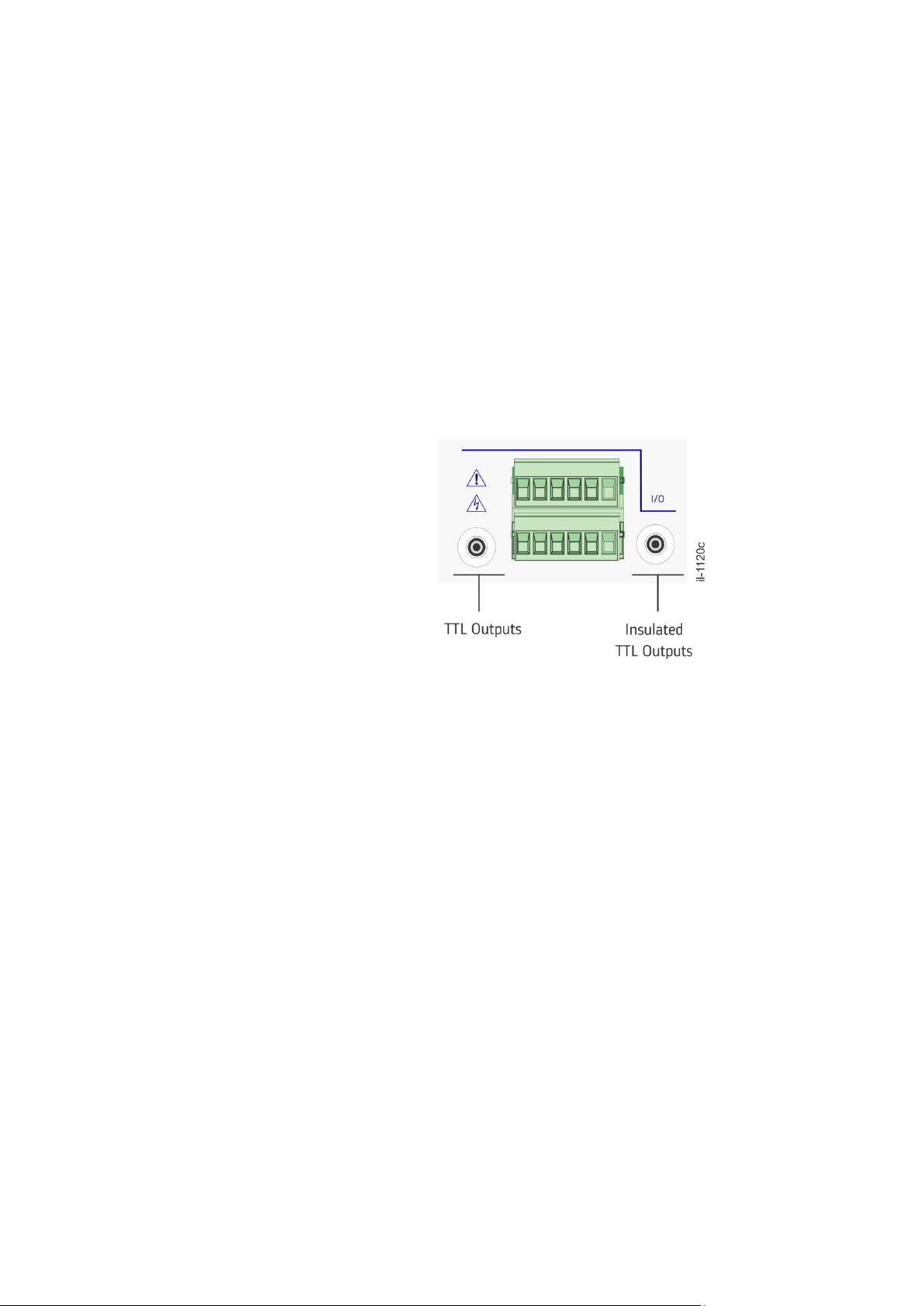
The rear panel of the RT430/434 comprises:
Two power supplies (one is optional), AC/DC high voltage or DC low voltage;
Two TTL electrical outputs (Euro Type connectors) for synchronization, one of
them insulated;
Page 25

Chapter 3 – Hardware Design
RT430/434
RT430/434
25
Two TTL electrical outputs (BNC connectors) for synchronization, one of them
insulated;
Two open collector outputs;
Locked contactor relay and one CMOS/TTL level input;
One amplitude-modulated output for IRIG-B124 signal;
Two optical outputs;
RS232 and RS422/485 serial ports;
Two Ethernet network communication ports for the RT430 and four Ethernet
ports for the RT434;
GNSS antenna input.
Refer to figures below to the rear connection of the RT430 and RT434, respectively.
Figure 4: Rear view of RT430
Figure 5: Rear view of RT434
3 Network Ports
The network interface presents the following features depending on the equipment
version:
1. Monitoring and configuration;
2. NTP/SNTP synchronization protocols;
3. IEEE 1588 PTP synchronization protocol;
4. PRP Parallel Redundancy Protocol (only in RT430).
4 Power Supply
Apart from the main power supply, there is a redundant power supply available for
RT430 and RT434. Each power supply can have the nominal voltage ranges as listed
below:
1. 100-240Vac, 110-250Vdc;
2. 24-48Vdc.
Note the redundant power supply is independent from the main one. Please refer to
technical specification for the operating ranges.
Page 26

RT430/434
Chapter 4 – Installation
26
RT430/434
Reason RT430/RT434
GNSS Precision-Time Clock
Chapter 4: Installation
This chapter describes how the RT430 and RT434 must be installed.
1 Unpacking
Unpack the unit carefully and make sure all the accessories and cables are put aside
so they will not be lost.
Check the contents against the packing list that goes with the product. If any of the
content listed is missing, please contact GE Grid Solutions (see contact information in
Maintenance chapter).
Examine the unit for any shipping damage. If the unit is damaged or fails to operate,
notify the shipping company without delay. Only the consignee (the person or
company receiving the unity) can file a claim against the carrier for shipping damage.
We recommend you to keep the original packing materials for possible transport in
the future.
Normal Use of the Equipment
In order to maintain the equipment integrity, levels of protection and assure user
safety, the RT430/434 must be installed in an enclosed panel with recommended
ingress protection rating of IP54 or above.
The enclosing panel must ensure that the equipment rear connections and sides are
unexposed and protected against impact and water, whilst maintaining adequate
temperature and humidity condition for the devices. Furthermore, the equipment
must have all their rear connectors attached, even if not being used, to keep their
levels of ingress protection as high as possible.
During the normal use of the device only the front panel will be accessible.
External Indications
Connector descriptions, serial number and part number are shown on an external
label positioned on the equipment, as illustrated on below.
Figure 6: Location of Serial number, part number and outputs description.
Page 27
Chapter 4 – Installation
RT430/434
RT430/434
27
2 Mounting
The equipment has been designed to be mounted in a standard 19-inch rack using
four M6x15 screws.
Keep adequate clearance for all connections. In particular, the optical fiber cables
should be installed in compliance with the 30 mm minimum bending radius.
For more information regarding the equipment dimensions, refer to the Technical
Specification chapter.
Power Supply
The unit can be powered from a DC or AC power supply within the limits specified. If
the redundancy power supply was ordered, the two power supplies should be
provided independently to ensure operation if one of them is interrupted.
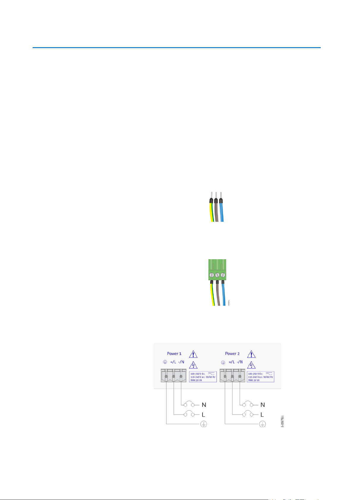
All power connections must use insulated flameproof flexible cable with a 1.5 mm²
cross section, 70 °C thermal class, and 750 V insulation voltage.
To reduce the risk of electrical shock, pre-insulated tubular pin terminals should be
used on the ends of the power connections.
Figure 7: Pre-insulated tubular pin terminals
The pin terminals must be completely inserted into the connector supplied with the
unity so that no metallic parts are exposed, according to the figure below.
Figure 8: Supply connector assembly
A 1.5 mm² ground lead must be connected to the terminal marked with the
protective ground symbol for safety.
Figure 9: RT430/RT434 Power Connection
Page 28

RT430/434
Chapter 4 – Installation
28
RT430/434
For AC power connection, the phase conductor must be applied to terminal (+/L),
neutral conductor to terminal (-/N) in each of the supply terminals identified, Power 1
and Power 2.
For DC power connection, the positive line should be applied to terminal (+/L),
negative to terminal (-/N) in each of the supply terminals identified, Power 1 and
Power 2.
For compliance with IEC 61010, install a suitable external switch or circuit breaker in
each current-carrying conductor of RT430/434 power supply; this device must
interrupt both the hot (+/L) and neutral (-/N) power leads. An external 10 A, category
C, bipolar circuit-breaker is recommended. The circuit breaker should have an
interruption capacity of at least 25 kA and comply with IEC 60947-2. The switch or
circuit-breaker must be suitably located and easily reachable, also it must not
interrupt the protective ground conductor.
Grounding (Earthing)
To ensure proper operation of the equipment under extreme electromagnetic
conditions, connect the equipment protective ground terminal to the panel using a
copper strap of at least 10 mm width as M6 ring lug.
Figure 10: RT430/434 Grounding Strap
GNSS Antenna Terminal
A 3.3-Volt active GNSS antenna (100 mA max loading) must be connected to the
antenna input terminal when satellites are being used as time reference.
Figure 11: GNSS antenna connector
If the GNSS antenna is connected and it is possible to receive signal from at least 4
satellites the LOCKED indicator will start to blink after a couple of seconds, indicating
that the internal time-base is being synchronized with the satellites. The LOCKED
indicator will stop blinking and will remain lit as soon as maximum accuracy is
achieved. This process may take several minutes if the equipment was transported
Page 29

Chapter 4 – Installation
RT430/434
RT430/434
29
for more than a few hundred kilometers or was unpowered for many weeks. The drycontact LOCKED in the rear panel closes when maximum accuracy is achieved.
The antenna must be mounted outdoors, in a vertical position, with an unobstructed
view of the sky. The antenna should be placed above the height of the building as
much as possible. A partially obstructed sky view will compromise the unit's
performance.
Figure 12: Recommended position for installing the GNSS Antenna
The antenna should not be located under overhead power lines or other electric light
or power circuits, or from where it can fall onto such power lines or circuits.
An antenna mast of roof-mounting-kit and any supporting structure must be
properly grounded to provide protection against voltage surges and built-up static
charges. It is recommended the use of a surge arrester for the entire wiring where
there is external antenna cabling.
The antenna must be connected to the unit by using a coaxial cable with a 50 Ω
impedance. The antenna cable should be routed through a conduit, shielded from
rain and/or solar radiation. The conduit should not be shared with any power circuits.
It is recommended to use a 3/4 PVC conduit, threaded on one end. To install it, cut
down to the intended size and screw the antenna in the conduit. The conduit can be
fixed on the wall, so that the antenna is above the wall limit and free from lateral
obstacles, as shown in the next figure.
Figure 13: Recommended position GNSS Antenna conduit installation
Page 30
RT430/434
Chapter 4 – Installation
30
RT430/434
Cables with lengths ranging from 15 m (50 ft) to 100 m (328 ft) can be ordered from
GE Grid Solutions. For use of antennas and cables from other manufacturers, contact
GE Grid Solutions for evaluation.
The antenna cable affects the unit's performance in two distinct ways: satellite signal
attenuation and propagation delay.
TTL Electrical Outputs
The RT430/434 has 4 electrical outputs, 2 screw connectors, and 2 BNC connectors.
One output of each connector type is insulated.
The type of signal at each output can be configured through a Web Interface to
generate IRIG-B004, DCF77, 1PPS, 1PPM, 100PPS, or any custom-defined low
frequency, from 1 pulse-every-two-seconds to 1 pulse-per-day. In addition, it is
possible to configure the outputs to generate daily set-time pulses. The polarity of the
signal and the pulse width can also be configured.
Figure 14: TTL electrical outputs
More than one device can be connected in parallel from one TTL output. The
maximum number of devices that can be connected to the TTL output depends on
the current that each device’s input uses. As the maximum current supplied from
each TTL output is 150mA, the sum of the currents from all devices connected cannot
exceed this value (cable resistance should be considered). The TTL voltage level is 5V.
Electrical cable length should not exceed 100m. To minimize EMC effects in IRIG-B
signals, the use of fiber-optic cable is recommended for distances greater than 3 m.
For details on the configuration of TTL-Level electrical outputs, refer to the
Configuration chapter.
See the Technical Specification chapter for more description of signal levels and
maximum ratings.
Open-Collector Electrical Outputs
The unit has 2 open-collector electrical outputs, and the electrical cable length
should not exceed 100m.
The type of signal at each output can be configured through a Web Interface to
generate IRIG-B004, DCF77, 1PPS, 1PPM, 100PPS, or any custom-defined low
frequency, from 1 pulse-every-two-seconds to 1 pulse-per-day. In addition, it is
possible to configure the outputs to generate daily set-time pulses. The polarity of the
signal and the pulse width can also be configured.
Page 31

Chapter 4 – Installation
RT430/434
RT430/434
31
Figure 15: Open collector electrical outputs
The open-collector outputs require the use of an external resistor properly sized to
limit current to a value below 300 mA.
Figure 16: Connection diagram of the open-collector electrical outputs
To scale the resistor use the relationship:
Where Vc is the external voltage to be switched by the open-collector output.
The resistor power should be adequate for the voltage and current values to be
switched, i.e.
Do not connect the open-collector electrical outputs without a properly sized
external resistor or another appropriate mechanism to limit current.
See the Technical Specification chapter for a description of signal levels and
maximum ratings.
Optical Outputs
RT430/434 has 2 outputs for multimode optical fiber. The length of fiber-optic cables
should not exceed 2 km.
The type of signal at each output can be configured through a Web Interface to
generate IRIG-B004, DCF77, 1PPS, 1PPM, 100PPS, or any custom-defined low
frequency, from 1 pulse-every-two-seconds to 1 pulse-per-day. In addition, it is
possible to configure the outputs to generate daily set-time pulses. The polarity of the
signal and the pulse width can also be configured.
Page 32

RT430/434
Chapter 4 – Installation
32
RT430/434
Figure 17: Optical outputs
See the Technical Specification chapter for optical outputs technical information.
Amplitude Modulated Output
The RT430/434 has one amplitude-modulated output, which generates an IRIG-B124
signal. Use coaxial cables with an impedance of 50 Ω and a BNC connector on this
output. See the Technical Specification chapter for the signal levels description.
Figure 18: Amplitude modulated output
Serial Port (RS232, RS422/485)
The serial port is compatible with the RS232 and RS422/485 standard (DTE pinlayout). The RS422/485 is capable of synchronizing up to 32 devices.
Figure 19: Serial port RS232 and RS422/485
Table 1: Serial port pinout
DB9 male
Signal
1 - 2
TXD (used to send the datagram)
3
RXD
Page 33

Chapter 4 – Installation
RT430/434
RT430/434
33
4
OUT (RS232 level output with user-programmable signal)
5
GND
6 - 7
V+ (RS232 level voltage reference of the internal converter)
8
422/485 TX+
9
422/485 TX-
The bit-rate, format (number of data bits, party, number of stop bits) and datagram
type can be configured using the Web Interface, as well as the type of signal
transmitted by the pin OUT (pin 4).
Pins 2, 3 and 5 are used for the RS232 interface.
Pins 8 and 9 are used for the RS422 or RS485 interface.
For serial port configuration, see the Configuration chapter.
For existing datagrams details, see Appendix.
Dry-Contact Relay
The RT430/434 has 1 dry-contact that can be used to remotely signal the locked
state of the unity and to alarm if there is no power on the unit.
Figure 20: Dry-contact relay
When the unit is powered up, the dry-contact relay is normally closed. When the
equipment enters in the locked state, the dry-contact will open. The dry-contact
closes in case the unit does not have enough satellites as reference or the power
supply has failed.
See the Technical Specification chapter for information on switching capacity
limitations.
Event Input
The RT430/434 has 1 input to detect TTL-Level external events. This input may be
used to verify the PTP signal quality when RT430/434 synchronizes another clock
using PTP. Thus, the TTL output from the PTP Slave clock may be connected to the
event input from RT430/434 in order to measure the signal quality. is used as a slave
(PTP signal received from external source via network).
Page 34

RT430/434
Chapter 4 – Installation
34
RT430/434
The electrical output from the PTP Slave clock should be configured to send pulses in
a time frequency and an event will be registered in a log file containing the pulse
timestamp for each received pulse. The input accuracy is in the magnitude of ns.
Figure 21: Event input
Euro Type Connections
The following information is available in the top of the unit, but if the equipment is
already installed in the panel, it may be useful when handling the Euro Type
connector for TTL outputs, Open collector, Locked relay and event input.
Figure 22: Euro Type label for connections
Numbers 1 and 2: Open collector outputs;
Number 3: Locked (dry contact) relay;
Number 4: Isolated TTL output;
Number 5: Event input;
Number 6: Non-isolated TTL output.
3 Ethernet Communication
The RT430 has 2 Ethernet 10/100BaseT (auto-negotiation) communication interfaces
with RJ45 connectors, and the RT434 has 4 Ethernet 10/100BaseT (auto-negotiation)
ports.
When a CAT5 cable with RJ45 connector is plugged in each port, the LINK led will
indicate that the cable is transmitting signal, and the ACTIVITY led blinks when there is
data exchange.
Page 35

Chapter 4 – Installation
RT430/434
RT430/434
35
Figure 23: Electrical communication interface via Ethernet network
Factory default settings
Table 2: Ethernet port 1 default settings
IP Address
192.168.0.199
Netmask
255.255.255.0
Broadcast
192.168.0.255
Table 3: Ethernet port 2 default settings
IP Address
192.168.1.199
Netmask
255.255.255.0
Broadcast
192.168.1.255
Table 4: Ethernet port 3 default settings (RT434)
IP Address
192.168.2.199
Netmask
255.255.255.0
Broadcast
192.168.2.255
Table 5: Ethernet port 4 default settings (RT434)
IP Address
192.168.3.199
Netmask
255.255.255.0
Broadcast
192.168.3.255
The factory’s default port to connect to the Gateway is the Ethernet 1. The factory
default settings of the Gateway and DNS Server are:
Page 36

RT430/434
Chapter 4 – Installation
36
RT430/434
Table 6: Gateway and DNS Server default settings
Gateway (Ethernet 1)
192.168.0.254
Server DNS
192.168.0.254
The Ethernet parameters can be configured through the Web Interface.
Network port and communication protocols
To ensure unrestricted access to communication via Ethernet network, the following
ports and protocols should be enabled:
Table 7: Gateway and DNS Server
Port
Protocol
Description
80
TCP/IP
Remote access via Web
123
UDP
NTP/SNTP Time synchronization
161
UDP
SNMP for equipment monitoring
319
UDP
Sending event messages PTP to synchronize
320
UDP
Sending general messages via PTP to synchronize
443
HTTPS
Establishing a safe connection via Web interface
Equipment access
The Web Interface is designed for configuring and monitoring the unit through a web
browser, if the unit it is accessible from a local network. To use all features through
the Web Interface, make sure to use one of the following web browsers:
Internet Explorer version 7.0 or newer.
Mozilla Firefox version 3.0 or newer.
Google Chrome
Connect to the Web Interface by entering the unit IP address into the address field of
your web browser. After the page is loaded, the unit’s Web Interface will open,
allowing the user to operate, monitor, and configure it.
4 Powering Up
Before energizing the unit, familiarize yourself with all the risks and attention
indicators in the equipment frame.
Connect the power supply (including the ground lead) to the appropriate
terminals.
Page 37

Chapter 4 – Installation
RT430/434
RT430/434
37
The unit will perform a self-test procedure, and the Alarm indicator will remain
lit.
At the end of the self-test, the equipment will perform initialization of the GNSS
receiver. At the end of approximately one minute, the Alarm indicator will go out
and information will be shown in the equipment's display. If Alarm indicator
remains on, the unit will not be operating and it will require attention by the
user.
To turn off the unit, switch off the external switch or circuit breaker. The unit will
record the time, date, satellite orbits parameters, and internal oscillators drift
estimates in non-volatile memory to improve accuracy and reduce the time to
synchronize with satellites in the next energizing process. Also, all indicators
LEDs will turn off.
In case the unit does not behave in a way here described, carefully check all power
and signal connections. See Maintenance chapter for additional suggestion for
problem diagnosis.
5 Preventive Maintenance Actions
In view of the critical nature of the application, GE products should be checked at
regular intervals to confirm they are operating correctly. GE products are designed
for a life in excess of 20 years.
The devices are self-supervising and so require less maintenance than earlier designs
of protection devices. Most problems will result in an alarm, indicating that remedial
action should be taken. However, some periodic tests should be carried out to ensure
that they are functioning correctly and that the external wiring is intact.
It is the responsibility of the customer to define the interval between maintenance
periods. If your organization has a Preventative Maintenance Policy, the
recommended product checks should be included in the regular program.
Maintenance periods depend on many factors, such as:
The operating environment;
The accessibility of the site;
The amount of available manpower;
The importance of the installation in the power system;
The consequences of failure.
Preventive Actions
For optimum performance of Reason RT430/434, perform the following preventive
maintenance procedures and actions:
Keep temperature and humidity at adequate levels inside the panel. The American
Society of Heating, Refrigerating, and Air Conditioning Engineers (ASHRAE)
recommends operating network equipment within the following ranges of
temperature and relative humidity (see the ASSHRAE TC9.9 “2011 Thermal Guidelines
for Data Processing Environments – Expanded Data Center Classes and Usage
Guidance”).
Temperature within 18° C to 27° C (64.4° F to 80.6° F)
Relative humidity less than 60%
Dew point within the range of 5.5° C to 15° C (41.9° F to 59.0° F)
Page 38

RT430/434
Chapter 4 – Installation
38
RT430/434
Operating within this range supports the highest degree of equipment reliability, even
though the equipment data sheets may state wider ranges of minimum and
maximum temperature and humidity (for example, -40° C to 55° C and 5% to 95%
RH). Continuous equipment operation at the minimum and maximum limits is not
recommended.
Keep panel sealed to avoid dust and/or animals and insects.
Inspect the installation site for moisture, loose wires or cables, and excessive dust.
Make sure that airflow is unobstructed around the device and into the air intake
vents.
It is recommended weekly or every two weeks to access the web interface area of
the unit and check the equipment details in Status area. See Operation chapter for
further details regarding the equipment status.
If any abnormal conditions are observed, refer to Maintenance chapter or contact
the technical support team to obtain the suitable instructions to deal with the issue.
Page 39

Page 40

RT430/434
Chapter 5 – Operation
40
RT430/434
Reason RT430/RT434
GNSS Precision-Time Clock
Chapter 5: Operation
This chapter introduces the Local and Remote Interface available for RT430/434.
1 Local Interface (HMI)
The RT430/434 front panel consists of a LCD display, two indicators and buttons to
navigate through the screen. The figure below illustrates the equipment’s front view.
Figure 24: Local Interface from RT430 and RT434
The RT430/434 has an LCD display (20 columns x 2 lines) for time monitoring and
network setup. The display's first screen shows temporal reference information: day
of the week, day, month, year, day of the year, hours, minutes, seconds, time zone
and the number of monitored satellites.
By navigating through the display using the buttons (arrows pointing right and left), it
is possible to check the configuration of the equipment's two Ethernet networks. IP
addresses, network mask, gateway, broadcast and DNS server are shown for each
network. The following illustration presents the possible menu screens for the RT430.
The RT434 menu has the same screens as the RT430, but informing about all 4
Ethernet ports.
Figure 25: Navigating the RT430’s local monitoring display
The Locked indicator shows that unit is synchronized with time references from
satellites. This indicator blinks when the unit is searching for orbit data from satellites,
which is a common situation if the unit has been moved over long distances or has
been out of operation for a long period. This indicator will turn off as soon as the
external reference is lost.
Page 41

Chapter 5 – Operation
RT430/434
RT430/434
41
The Alarm indicator will light up for a brief period while the unit powers up. After
concluding the initialization, the unit will start operating and this indicator should turn
off. If Alarm indicator remains on, the unit is not operating normally and will require
user attention. The Alarm will also light up in case a problem occurs with the antenna
or after 66 seconds in unlocked state.
2 Web Interface (Remote Access)
The RT430/434 has a Web Interface for monitoring and configuring the unit. This
section describes how to monitor the RT430/434 status in real time, check general
system information and to log external timestamps pulses.
To connect to the Web Interface, enter the unit Ethernet port IP address into the
address field of a web browser. For information on factory defaults for the Ethernet
port, see the Installation chapter. If the unit is not using factory default settings, the
current IP address can be obtained by the local HMI (LCD display and keys).
A start page containing the unit status information opens the Web Interface. The
remaining monitoring and configuring sections are on a menu on the left. To access
them, click the desired menu item.
Figure 26: RT430 Web Interface
Web Interface Language
The Web Interface is available in five different languages: English, French, Spanish,
Portuguese, Russian. To choose the language refer to the globe figure in the upperright corner.
Figure 27: Languages available in the Web Interface
Page 42

RT430/434
Chapter 5 – Operation
42
RT430/434
3 Monitoring Menus – Web Interface
The following sections will describe the monitoring menus from the Web Interface:
Status: monitoring the status of the unit in real time.
General Information: information of the unit system.
Event Log: timestamp pulses received from another time source.
Status
The section Status of Web Interface, as shown below, allows monitoring status
information of the unit in real time.
Figure 28: Section to monitor the status of the unit in the Web Interface
The unit status information is grouped into areas, as follows:
Equipment: shows operational information of the unit.
o Locked: indicates if the unit is in the locked state or not. If yes, the
number of monitored satellites is indicated.
o Antenna: indicates if the GNSS antenna is properly connected to
the unit.
o Alarm: indicates if the unit is presenting internal failure.
Time: presents the local time, UTC, off-set and time zone.
Position: latitude, longitude and altitude information.
PTP: shows status from PTP protocol, the time inaccuracy, GrandMaster Identity
and the state from each port.
NTP: presents the NTP information, including NTP stratum. The NTP graphic
illustrates the NTP offset time and the NTP Client List displays all NTP clients that
have recently sent requests to RT430/434. NTP Clients will appear up to 1 hour
Page 43

Chapter 5 – Operation
RT430/434
RT430/434
43
after from last NTP request sent. Both NTP Graphic and NTP Client List does not
have automatic refresh.
Channels: monitored satellites information (number, phase noise, azimuth and
elevation). The background of Satellite number (Sat #) is green when receiving
the health ephemeris data. A grey background means the satellite is not
healthy by the moment, and it is not been used as reference.
General Information
The section General Information of the Web Interface displays system information of
the unit.
Figure 29: Section to visualize general information of the system
The system information is as follows:
Firmware Version: presents the current firmware version of unit.
Hardware Version: presents the hardware version of unit.
Serial Number: presents the serial number of unit.
MAC Address Ethernet 1/4: presents the MAC address of each Ethernet port.
Key: partially displays the equipment key according to the cortec.
Ethernet Ports: presents the status of NTP and PTP.
PRP: presents the status of PRP (RT430 only).
Event Log
The section Event Log from the Web Interface allows monitoring external timestamp
pulses received from another time source. The timestamp frequency registered in log
files is according to the pulse frequency received through the event input.
Page 44

RT430/434
Chapter 5 – Operation
44
RT430/434
Figure 30: Section of Web Interface to monitor timestamps of event input
Last Events: In the Timestamp area, it is possible to view the last ten
timestamps from a signal received through the event input. The update of
timestamps is not automatic. To view them, click the button <Update>.
Timestamps Log file: a .txt format file, containing the timestamps registered in
the unit. By clicking <Download> a window will open to save the file in a
directory on the computer.
The RT430/434 event input can register up to 3600 timestamps.
Page 45

Charter 6 – Configuration
RT430/434
RT430/434
45
Reason RT430/RT434
GNSS Precision-Time Clock
Chapter 6: Configuration
This chapter describes how to configure the RT430/434.
1 Web Interface
The Reason RT430/434 GNSS Precision-Time Clock has a Web Interface for
configuring network parameters, time parameters, time synchronization outputs and
PTP standard, updating firmware, changing key, controlling access and manipulating
configurations.
To connect to the Web Interface, enter the unit Ethernet port IP address into the
address field of a web browser. For information on factory default settings of the
Ethernet ports, see Installation chapter. If the unit is not using factory default
settings, the current IP address can be obtained by the local HMI (LCD display and
keys).
A start page containing the unit status information opens once the Web Interface is
accessed. The remaining monitoring and configuring sections are on a menu on the
left. To access them, click the desired menu item. The configuring sections are:
Ethernet: allows configuring the network parameters.
Time Settings: allows configuring the time parameters.
Time Signals: allows configuring signals sent from outputs.
PTP: allows configuring PTP clock parameters in accordance with IEEE 1588.
Setup: allows manipulating configurations, changing access control and key,
and updating firmware.
User Name and Password
The configuration sections should be edited one by one and at the end of each
section, it is necessary to transmit the changes made to the unit. Otherwise, the
changes will not be saved. When transmitting changes to the unit, username and
password will be required. Factory default username and password are:
Table 8: Factory default username and password
User name
configuration
Password
1234
Sending Configuration
To send the new configuration to the equipment, click on the <Apply> button. Then
the username and password of the equipment will be requested.
Page 46

RT430/434
Chapter 6 – Configuration
46
RT430/434
Once both entered, click on login and the equipment will update its configuration. A
message will be displayed informing the status of the update.
In case the new configuration is not transmitted to the unit, the changes will not be
saved and will be discarded once the Web Interface is closed.
2 Ethernet
The Ethernet section of the Web Interface allows enabling the PRP (only in RT430) and
configuring network parameters of Ethernet ports 1, and 2, gateway and DNS. RT434
will display four Ethernet ports.
Figure 31: Section to configure network parameters of the unit
PRP (only in RT430)
To enable the Parallel Redundancy Protocol check the PRP Enabled box, as shown
below, and click on the <Apply> button. When using PRP, the Ethernet port 2 uses the
same Network parameters from Ethernet port 1. For this reason, the Ethernet 2
configuration keeps disable when PRP is enabled.
Page 47

Charter 6 – Configuration
RT430/434
RT430/434
47
Figure 32: Enabling the PRP redundancy
Ethernet Ports
The Ethernet ports allow communication via TCP/IP or UDP/IP networks.
MAC Address: informs the MAC address of the network port.
The IP Address field allows entering the IP address of the network port (only
decimal numbers).
The Network Mask field allows entering the network mask from the network to
which the unit will be connected (only decimal numbers).
The Broadcast field allows entering the subnet address to which the unit will be
connected (only decimal numbers).
Default Gateway
The gateway configuration allows RT430/434 to communicate with other devices
connected to a local subnet.
The IP Address field allows entering the network port IP address of the unit (only
decimal numbers).
The field Port allows choosing the communication port to be used as gateway
DNS Server
The DNS server configuration allows the RT430/434 to communicate with the DNS
server from a local subnet. The IP Address field allows entering the IP Address of the
network's name server (only decimal numbers).
Ethernet - Configuration Summary
Page 48

RT430/434
Chapter 6 – Configuration
48
RT430/434
The table below presents all configurable network parameters and its possible values
and variables.
Table 9: Summary of configurable network parameters
Ethernet Ports
MAC Address
00:00:00:00:00:00
Not configurable
IP Address
0.0.0.0
Only decimal numbers
Network Mask
0.0.0.0
Only decimal numbers
Broadcast
0.0.0.0
Only decimal numbers
Gateway
IP Address
0.0.0.0
Only decimal numbers
Port
Ethernet port 1, 2, 3* or 4*
Selectable
DNS Server
IP Address
0.0.0.0
Only decimal numbers
* only in RT434
3 Time Settings
The Time Settings section of the Web Interface allows configuring time parameters.
Figure 33: Section to configure time parameters
Time Parameters
The field Timezone allows configuring the time zone of the unit, and converting
UTC time to local time. Half hour time zones are supported.
The field DST, when enabled, allows configuring the beginning and the end of
Daylight Saving Time.
Page 49

Charter 6 – Configuration
RT430/434
RT430/434
49
When the option NTP – Send local time is selected, the local time is sent through
NTP protocol. If this option is unselected, the UTC is sent.
If NTP function was ordered, it is activated by default operating at unicast
(client/server) mode.
Leap Second
The RT430/434 has built-in support for leap seconds, whenever indicated by the
GNSS (when operating as GNSS Clock) or by PTP Grandmaster (when operating as
PTP Slave).
In both cases, the LCD display will show 23:59:60 at the moment the second
increases (leap). In other words, while the last second of a normal day is 23:59:59, the
last second of a day with Leap Second is 23:59:60.
This can also be verified in the Web Interface, under the NTP information of the
Status section. The first field, "leap", indicates whether a leap second will be applied
at the end of the day. Its standard value is 0 (normal, leap second warning). This field
has the value 1 if the last minute of the day has 61 seconds; or the value 2 if the last
minute of the day has 59 seconds. So from the beginning of the day that will take
place the Leap Second field will have a value of 1 or 2; after the application of the
Leap Second this field value is back to its normal value 0.
Besides the Web Interface, leap second treatment is also stored on the equipment’s
event log, and may be checked after the occurrence of a leap. The processing and
treatment of the Leap Second happens automatically and may not be disabled.
Time Settings - Configuration Summary
The table below presents all configurable time parameters and its possible values
and variables.
Table 10: Summary of configurable time parameters
Timezone
h: from -12 to +14 (hours)
m: 00 or 30 (minutes)
DST
selected: DST enabled
unselected: DST disabled
Start/End
h: 00 up to 23 (hours)
m: 00 up to 60 (minutes)
first, second, third or last (week of the month)
Sunday, Monday, Tuesday, Wednesday, Thursday, Friday or
Saturday (day of the week)
January, February, March, April, May, June, July, August,
September, October, November or December (month)
Page 50

RT430/434
Chapter 6 – Configuration
50
RT430/434
4 Time Signals
The Time Signals section of the Web Interface allows configuring the signals applied
to the outputs of the unit. See figure below:
Figure 34: Section to configure time signals applied in the outputs
Outputs
TTL 1 / 2: allows configuring the TTL-level electrical outputs 1 and 2. Each
output has two terminals, one screw, and other BNC. Both terminals can be
used simultaneously although its configuration is unique, so the same signal
will be applied to both terminals;
OPTO 1 / 2: allows configuring the two TTL-Level optical outputs;
OC 1 / 2: allows configuring the two open collector outputs;
RS232: allows configuring the Out pine signal of the serial output.
Page 51

Charter 6 – Configuration
RT430/434
RT430/434
51
For each electrical, optical, open collector and serial output, it is possible to configure
the following signals:
OFF - Output turned off;
PPS - Output with 1 pulse-per-second;
100PPS - Output with 100 pulses-per-second;
PPX - Output with programmable frequency pulses;
PPM - Output with 1 pulse-per-minute;
TMARK - Output with programmable time;
DMARK - Output with programmable date and time;
IRIG-B - Output with IRIG-B004 signal;
DCF77 - Output with DCF77 signal.
It is also possible to choose normal or inverted polarity for each output individually.
The field TMARK allows configuring time to generate a pulse with daily
repetition. All outputs programmed to send TMARK pulses will be programmed
within the same time.
The field DMARK allow to set a date and time for a single pulse signal. All
outputs using DMARK will be programmed to this same date and time.
The field PPX allows configuring a pulse-frequency that can vary from 1 pulse-
every-2-seconds to 1 pulse-per-day. All outputs programmed to send PPX
pulses will be programmed within the same pulse-frequency.
The field Pulse Width allows the user to adjust the duty cycle (pulse width of
high state) for PPS, PPM, PPX, TMARK and DMARK.
Pulse width of 1µs when unlocked: When selected, this option turns the PPS,
PPM, PPX, TMARK and DMARK pulses into a 1µs pulse when not locked to
satellites, indicating that the synchronization signal is local, not global.
Disable PPS when unlock time after (s): When selected, this option disables the
PPS signal after the specified time, in seconds.
The field Cable delay compensation allows entering a value between 0 and 999
nanoseconds (ns) to compensate propagation delay according to the cable
length. Refer to Appendix D for more details of how to compensate the cable
delay.
Serial datagram
The field Datagram allows configuring a datagram sent by the serial port (TDx
pin).
ACEB, NEMEA, GPZDA, Meinberg and customizable datagrams are possible.
When choosing a customizable datagram, it is necessary to enter characters
with information required. For more details about ACEB, NEMEA, GPZDA and
Meinberg datagrams, see Appendix C;
A serial datagram is sent each second. The field On-time mark allows choosing
if the sending will be synchronized with the beginning or the end of the
datagram;
o Start of first: pulse synchronized with the beginning of the
datagram;
o Start of last: pulse synchronized with the end of the datagram;
Serial: allows configuring the serial port parameters.
Page 52

RT430/434
Chapter 6 – Configuration
52
RT430/434
o The field Speed allows choosing data transmission speed of the
serial port, which can be 38400, 19200, 9600, 4800 or 1200 bps;
o The field Data allows defining the data bits, which can be 7 or 8;
o The field Parity allows choosing the serial port parity, which can be
odd, even, or none;
o The field Stop bit allows choosing the datagram stop bit, which can
be 1 or 2.
Customizable datagrams
The RT430/434 allows defining a datagram “ASCII'' to be sent once per second by the
serial port, using the characters described below. The datagram characters can be
single or special. The maximum number of character in a customizable datagram is
16.
The single characters allowed are: 0..9 A..Z a..z $ \{ \} ( ) [ ] . , ; : ! ? @ < >$ \# * \_ - \% \$
blank and empty.
%H %M %S %d %m %y %x correspond to 2 characters; (Date and Time sent
through datagrams refers to the local time zone configured in the RT430/434)
%j : correspond to 3 characters (length(str) + 1 for each event);
%Y correspond to 4 characters (length(str) + 2 for each event)
%u %w %s %o %O %Q %1 %2 %3 %4 %5 %% : correspond to 1 character
(length(str) - 1 for each event)
The following special characters can be used to enter information into the datagram:
Table 11: Customizable datagram special characters
Paramet.
Values
Num. of
Char.
Description
%H
00 ... 23
2
Hours
%M
00 ... 59
2
Minutes
%S
00 ... 59
2
Seconds
%j
001 ... 366
3
Day of the year
%d
01 ... 31
2
Day of the month
%m
01 ... 12
2
Month
%y
00 ... 99
2
Year (the last two digits)
%Y
2000 ... 2099
4
Year (four digits)
%u
1 ... 7
1
Day of the week (1 = Monday)
%w
0 ... 6
1
Day of the week (0 = Sunday)
Page 53

Charter 6 – Configuration
RT430/434
RT430/434
53
%s
‘S’ or ‘_’
1
DST (‘S’ if DST ‘_’ in odder case)
%o
‘_’ or ‘#’
1
Status (‘_’ if locked, ‘#’ in odder case)
%O
‘_’ or ‘*’
1
Status (‘_’ if locked, ‘*’ in odder case)
%Q
‘_’ or ‘?’
1
Status (‘_’ if locked, ‘?’ in odder case)
%1
<SOH>
1
Start-of-header (ASCII 01)
%2
<STX>
1
Start-of-text (ASCII 02)
%3
<ETX>
1
End-of-text (ASCII 03)
%4
<LF>
1
Line feed (ASCII 10)
%5
<CR>
1
Carriage returns (ASCII 13)
%x 2
Checksum type 1
%%
‘%’
1
Character ‘%’ (ASCII 37)
‘_’ is the character ‘blank (ASCII 32).
Checksum type 1 consists of two hexadecimal digits, which represent the result of a
XOR from all characters comprised between `\$' and `*' (`\$' e `*' not included). It is
useful for NMEA datagrams.
One example of serial datagram is presented below:
''Day:%d;Month:%m;Year:%Y;Hour:%H;Minute:%M;Second:%S;;%3''
Time Signals - Configuration Summary
The table below presents all configurable parameters for the time synchronization
outputs.
Table 12: Summary of all configurable parameters for outputs
Outputs
Output TTL 1 / 2
Signal: OFF, PPS, 100PPS, PPX, PPM, TMARK, DMARK,
IRIG-B or DCF77
Polarity: normal or inverted
Output OPTO 1 / 2
Signal: OFF, PPS, 100PPS, PPX, PPM, TMARK, DMARK,
IRIG-B or DCF77
Polarity: normal or inverted
Output OC 1 / 2
Signal: OFF, PPS, 100PPS, PPX, PPM, TMARK, DMARK,
Page 54

RT430/434
Chapter 6 – Configuration
54
RT430/434
IRIG-B or DCF77
Polarity: normal or inverted
RS232
Signal: OFF, PPS, 100PPS, PPX, PPM, TMARK, DMARK,
IRIG-B, DCF77 or EVENT
Polarity: normal or inverted
TMARK
Hour: 00 up to 23
Minutes: 00 up to 59
Seconds: 00 up to 59
DMARK
Year: from 2012 to 2030
Month: January to December
Day: 01 to 31
Hour: 00 up to 23
Minutes: 00 up to 59
Seconds: 00 up to 59
PPX
1 pulse-every-2-seconds to 1 pulse-per-day
Pulse width
PPS, PPM, PPX, TMARK and DMARK pulses width from 10
to 990 milliseconds
Pulse width of 1us
when unlocked
selected: PPS, PPM, PPX, TMARK and DMARK pulses
width of 1us when unit is unlocked
unselected: pulse width does not change when unit is
unlocked
Disable PPS when
unlock time after (s)
selected: disable PPS signal when the unit is unlocked
after defined period in seconds
unselected: maintain PPS signal when unit is unlocked
Cable delay
compensation
0 up to 999 nanoseconds
Serial datagram
Datagram
ACEB, NEMEA, GPZDA, Meinberg or Custom
On-time-mark
Char: start of first (start of first)
Char: start of last (start of last)
Serial
Speed: 38400, 19200, 9600, 4800, 2400 or 1200 bps
Data: 7 or 8
Parity: none, even or odd
Page 55

Charter 6 – Configuration
RT430/434
RT430/434
55
Stop bit: 1 or 2
5 PTP Configuration
The PTP section from Web Interface allows the user to configure the parameters for
the PTP protocol.
To enable the PTP in RT430/434, mark the “PTP Enabled” box. If the field “Force
operation as slave” is unmarked, the RT430/434 operates as Grandmaster Clock,
otherwise the unit acts as Ordinary Clock (slave). Note when equipment is operating
as Ordinary, the antenna signal is ignored.
To disable PTP, make sure both boxes, “PTP Enabled” and “Force operation as slave”,
are disabled.
Figure 35: Section to configure PTP parameters
Profile
When configuring PTP, the first point to be decided is which PTP profile, or which
common parameters, will be used along all PTP devices. The RT430/434 has four
options to be selected as profile:
Power Profile – IEEE C37.238/2011: profile with predetermined characteristics,
where the user cannot change any major parameter from PTP, such as Network
Protocol, Operation mode and Delay mechanism. The characteristics are shown
in next figure. The configurable parameters for Power Profile are:
o Domain number;
o VLAN ID and Priority;
o Operation as Master or Slave;
o If non-Power messages (PTP messages that are not in compliance
with IEEE C37.238) should be ignored;
o Grandmaster ID (identification);
o Network time inaccuracy, if delays are known from the network
architecture used;
o If the PTP should send the local time (considering the timezone and
DST parameters configured) or UTC time.
Page 56

RT430/434
Chapter 6 – Configuration
56
RT430/434
Figure 36: Characteristics from PTP Power Profile IEEE C37.238:2011
Power Utility – IEC/IEEE 61850-9-3/2016: profile with predetermined
characteristics, where the user cannot change any major parameter from PTP,
such as Network Protocol and Delay mechanism. The characteristics are shown
in next figure. The configurable parameters for Power Utility Profile are:
o Domain number;
o VLAN ID and Priority;
o Operation mode as One Step or Two Step;
o Operation as Master or Slave;
o If non-Power messages (PTP messages that are not in compliance
with IEEE C37.238) should be ignored;
o Send Alternate Time TLV – this option must be checked if
interoperability with Power Profile is required.
o If the PTP should send the local time (considering the timezone and
DST parameters configured) or UTC time.
Figure 37: Characteristics from PTP Power Profile IEEE C37.238:2011
Page 57

Charter 6 – Configuration
RT430/434
RT430/434
57
P2P Default: profile partly configurable, with some predetermined parameters,
which cannot be modified. The non-editable characteristics are shown in its
respective fields. The non-editable characteristics are.
o Domain number 0.
o Priority 128 in both Ethernet ports.
o Operation as master only.
Custom Profile: profile with all features freely configurable by a user.
Comparison between PTP Power Profiles
Table 13: Comparison between PTP Power Profiles
IEEE C37.238 PTP Power
Profile
IEC 61850-9-3 PTP Profile
for Power Utility
Automation
Network Protocol
Ethernet Layer 2
Ethernet Layer 2
Delay Mechanism
Peer-to-Peer (P2P)
Peer-to-Peer (P2P)
Operation Mode
One Step
One or Two Step(s)
TLV messages
Required
Optional
Grandmaster
Priority
Equal for all Grandmaster
Selectable, allowing to
choose the best
grandmaster for holdover
conditions
Domain number
The RT430/434 allows configuring the domain number to be identified by the PTP
clock, so it only answers messages from this domain. The domain number field
allows selecting a domain number between 0 and 255 which the unit will recognize.
Network protocol
This field defines the network layers where the PTP protocol will be applied. It is
possible to use PTP protocol in a network layer with IEEE 802.3 Ethernet (layer 2) or
UDP/IPv4 (layer 3) connection.
If Ethernet (layer 2) is selected, VLAN may be used.
Operation mode
The field operation mode allows configuring the operation mode according to the
form RT430/434 sends its messages, as follows:
One-step: Sync information and timestamp information are sent in the same
data packet;
Two-step: Sync information is sent in one data packet, and timestamp
information is sent in another data packet.
Page 58

RT430/434
Chapter 6 – Configuration
58
RT430/434
Delay mechanism
The RT430/434 is capable of measuring the delay between master and slave clocks
using End-to-end and Peer-to-peer, according to IEEE1588 standard. The field Delay
mechanism allows configuring the type of measurement of the delay, as follow:
End-to-end: measurement of delay across the network between master clock
and slave clock;
Peer-to-peer: measurement of delay only between master and slave clocks as
neighbors.
Grandmaster Priority
When configured as master, BMC algorithm tie breaking criteria priorities must be
attributed. The fields Grandmaster priority #1 and #2 allow configuring the priorities
of both Ethernet ports, in which #1 is the first and #2 is the last tie breaking criterion.
Between the first and the last tie breaking criterion, other clock characteristics are
analyzed. The priority values can vary from 0 to 255. The lower the attributed value is,
the higher its priority is.
PTP Messages
In PTP protocol, messages containing Sync information and timestamps are sent
across the network in multicast mode.
Announce messages are used to inform devices connected to the network about the
existence of a master clock available to send Sync packets. The clock connected to
the network operating as a master should send Sync messages. In case it is a twostep clock, Follow Up messages containing the timestamp will be send after the Sync
messages.
In RT430/434, it is possible to choose the frequency to send messages and the
waiting time of Announce message receipt, through the fields below:
Delay request interval allows choosing the frequency to send messages with
delay measurement. It is possible to configure the unit to send 16 messages per
second until one message every-32-seconds.
Announce interval allows choosing the frequency to send messages that apply
the device to become a network master candidate. It is possible to configure
the unit to send 16 messages per second until one message every-32-seconds.
Sync interval allows choosing the frequency to send Sync messages. It is
possible to configure the unit to send 16 messages per second until one
message every-32-seconds.
Announce receipt timeout allows choosing the waiting time of Announce
message receipt when RT430/434 is being used as slave. In case an Announce
message is not received within this time interval, the unit assumes that the
current master clock is unavailable and executes the BMC to select another
master clock. It is possible to configure values between 2 and 255 seconds.
PTP - Configuration Summary
The table below presents all configurable PTP parameters and its possible values and
variables.
Page 59

Charter 6 – Configuration
RT430/434
RT430/434
59
Table 14: Summary of configurable PTP parameters
Profile
Power IEEE C37.238
Predetermined parameters
Power Utility IEC
61850-9-3
Predetermined parameters
P2P Default
Domain number 0, priority 128, and operation as master
Custom
All parameters are configurable
Parameters
Domain number
From 0 to 255
Network protocol
UDP or Ethernet level 2
Operation mode
one-step or two-step
Delay
P2P or E2E
Grandmaster
Priority
# 1 from 0 to 255
# 2 from 0 to 255
For operation as
Slave: enables the use as slave
Intervals between sent messages
Delay request
From 1/16 to 32 seconds
Announce
From 1/16 to 32 seconds
Sync
From 1/16 to 32 seconds
Response time of messages
Announce receipt
From 2 to 255 seconds
TLV Messages
Send Alternate Time
TLV
Selected: TLV messages will be sent
Unselected: TLV messages will not be sent
UTC or Local Time
Send local time
Selected: local time is sent through PTP protocol.
Unselected: UTC is sent through PTP protocol.
Page 60

RT430/434
Chapter 6 – Configuration
60
RT430/434
6 Setup
The Setup section of the Web Interface allows updating the firmware, manipulating
configurations, changing key and configuring password. Firmware and key change
(equipment upgrade) instructions are described in Maintenance chapter.
Figure 38: Setup section in Web Interface
Page 61

Charter 6 – Configuration
RT430/434
RT430/434
61
Configuration Management
Backup Configuration: It is possible to receive a file with the current
configuration of the unit and store it in a directory on the computer. Saving the
final configuration of the unit as a backup is recommended.
o Download: allows saving the current configuration of the unit in
“.rt430” or “.rt434”, respectively to RT430 and RT434. By clicking
<Download> a window will open to save the file in a directory on
the computer.
Restore Configuration: It is possible to send a configuration file in “.rt430” or
“.rt434” format to the respectively unit.
o File: allows entering the directory and file name of the
configuration that will be sent to the unit.
o Search: allows searching the configuration file in Windows'
directories.
o Restore: allows transmitting the selected configuration file to the
unit. By clicking <Restore> a window will open requiring
configuration username and password. Enter the username and
password and click <Login>. To cancel the action, click <Cancel>.
During the transmission, the unit will go momentarily out of
operation.
Restore to factory default configuration: Restore the equipment to factory
default settings.
Password configuration
New password: allows entering a new password for configuration.
Confirm password: confirmation of the new password entered.
Reset Satellites Almanac
This option deletes the satellites Almanac data stored in the clock. Afterwards the
equipment will take several minutes to rebuild the Almanac.
The almanac consists of orbit courses and status information for each satellite in the
constellation, an ionosphere model, and information to relate satellites derived time
to Coordinated Universal Time (UTC).
Stationary Mode
This option enable the Stationary Mode, which keeps the equipment in locked state
even with one satellite. Note the equipment must track at least four satellites before
entering in stationary mode. Besides, if this option is enabled, the equipment must be
in a fixed position.
To enable the Stationary Mode, select the option “Enabled Stationary Mode” and click
on the <Apply> button.
Demo mode
Mostly used in demonstrations, this option forces the clock into a LOCKED state
independently if the antenna is or is not connected, as the internal oscillator is used
Page 62

RT430/434
Chapter 6 – Configuration
62
RT430/434
as time reference. In demo mode, the Locked Led will remain alight and the dry
contact relay opened. When the Demo Mode is activated, it is possible to configure
the date and time manually, in Time Settings tab from equipment Web Interface.
All time protocols work in Demo Mode: PTP, NTP, SNTP, IRIG-B and all other low
frequency signals.
Figure 39: Manual Time setting – only available in Demo Mode
Log Files
Technical support may request log files in case maintenance is required.
Reboot System
This feature reboots the system without the need to withdraw the power supply.
Page 63

Chapter 7 – Maintenance
RT430/434
RT430/434
63
Reason RT430/RT434
GNSS Precision-Time Clock
Chapter 7: Maintenance
This chapter describes the information to consider for an eventual maintenance.
For any further assistance required please contact the information and call center as
follows:
GE Grid Solutions:
Worldwide Contact Center
Web: www.GEGridSolutions.com/contact
Phone: +44 (0) 1785 250 070
1 Time Synchronization Failure (Locked Signaling)
The clock availability is higher than 99.95%, but time synchronization failure may
occur and the locked relay will alarm when it does. If availability rate is lower than
that, the follow actions are recommended:
Check for configuration being transmitted to the unit. During transmission, the
unit should momentarily go out of operation to reboot. This behavior is normal
and no action is required. The Locked indicator will lit as soon as the unit
resumes operation.
Make sure the GNSS antenna is properly connected to the unit.
Make sure the antenna cable being used is in accordance with the
specifications presented in Technical Specification.
Make sure the unit is synchronized with at least 4 satellites by checking the
Web Interface. Otherwise, check the location of the antenna, making sure that it
is installed according to the recommendations of Installation chapter.
If the unit is operating without time reference in the GNSS antenna, the failure may
be signaled in different ways: Local interface, Web Interface, signaling relay, and
data packets from IRIG-B, NTP, PTP and SNMP protocols.
Locked indicator (HMI)
The Locked indicator located in the front panel will be off when there is no time
reference in the GNSS antenna input. As soon as a GNSS antenna is connected, the
indicator will start blinking while it downloads a satellite almanac. This behavior is
normal and no actions are necessary. The Locked indicator will stop blinking and stay
lit as soon as the download is completed (it may take a few minutes when a unit is
moved over long distances or has been out of operation for a long period).
Page 64

RT430/434
Chapter 7 – Maintenance
64
RT430/434
Remote monitoring (Web Interface)
In the monitoring area of the Web Interface it is shown the information Locked and
the number of satellites when there is time reference in the GNSS antenna input, and
Unlocked when reference is disconnected.
Dry-contact relay (Locked)
The RT430/434 has a dry-contact normally closed for remotely signaling the locked
state of the unit. As the unit is powered up, the dry-contact Locked is normally closed.
The dry-contact relay operates along with the Locked indicator, and while RT430/434
is locked, the dry-contact relay is open. Thus, in case the unit loses satellite reference,
the dry-contact closes signaling the problem.
IRIG-B Signal
When the Time Quality bits from IRIG-B signal are all in 0, the unit is in Locked state,
i.e., there is time reference in the GNSS antenna input. In case the reference is
disconnected or the signal is weak, the bits combination will differ from zero.
PTP Protocol
In PTP protocol, there is a bit called time traceable that, when set, informs the
existence of time reference in the GNSS antenna input. Besides the existence of a
reference signal, it is possible to qualify the signal, according to the bits clock class
and clock accuracy, in which the criterion for assessing the quality of the signal is
configured in the device that receives the PTP messages.
NTP Protocol
In NTP protocol, information is given in layers, known as Stratum, numbered from 0
to 16. Layer 1 indicates the unit is operating with time reference from the GNSS
antenna input, and it is in LOCKED state. Layer 16 indicates the reference was
interrupted, i.e., the unit is not on LOCKED state. Also, the synchronization in this
protocol is updated every-2-minutes after the reference is interrupted.
SNTP Protocol
In SNTP protocol, a data set is sent containing time synchronization and the status of
the external time reference.
When the status data is zero, it represents the lack of time reference in the GNSS
antenna input. When it is 1, it represents the existence of reference in the GNSS
antenna input, i.e., it is in LOCKED state.
2 Firmware Update
Eventually, new firmware versions will be released with updates and improvements
to the unit.
The Setup section of the Web Interface allows updating the firmware, manipulating
configurations, changing key, and changing configuration username and password.
Page 65

Chapter 7 – Maintenance
RT430/434
RT430/434
65
Figure 40: Section to update firmware
To update the unit firmware, access the Setup section of the Web Interface by typing
the unit IP address in a default browser and follow the steps below:
1. Click <SEARCH> and it will allow the search of a new firmware update file in the
directories. Enter the directory and the firmware update file name in the <FILE>
field and it will be sent to the unit. The update file has the extension “.fw430” for
RT430 and “.fw434” for RT434.
2. Click < SEND> to send the new firmware to the unit.
3. After clicking <SEND>, a new window will open requesting username and
configuration password. Enter username and password and click <LOGIN>. To
cancel the action, click on <CANCEL>.
4. During the transmission, the unit will momentarily go out of operation.
5. After the change is completed, check the main page of the Web Interface.
Note: After updating, it is recommended to clear the browsing data (CTRL+ F5) when
accessing the web interface for the first time.
3 Equipment Upgrade - Key Change
It is possible to update the unit key in order to enable new features, according to the
commercial policy. Contact sales to acquire a new key to enable the desired features.
Figure 41: Section to equipment upgrade – key change
To change the unit key, access the Setup section from Web Interface, typing the unit
IP address in a default browser and follow the steps below:
1. Enter the new key (36 alphanumeric characters) in the Key field.
2. Click <Apply> to send the new key to the unit.
3. After clicking <Apply>, a new window will open requesting username and
configuration password. Enter username and password and click <Login>. To
cancel the action, click <Cancel>.
4. During the transmission, the unit will momentarily go out of operation. A
message communicating the key change will show up on the screen.
5. After the change is completed, check the main page of the Web Interface.
Page 66

RT430/434
Chapter 7 – Maintenance
66
RT430/434
4 Cleaning Instructions
Before cleaning the equipment, make sure that the primary voltage is removed. If it is
necessary cleaning the exterior of the equipment, use only a dry cloth. Internally it is
not required any cleaning.
5 Equipment Return
All parts and components comprising Reason devices must be repaired exclusively
by GE Grid Solutions. In case of equipment malfunction the customer must get in
contact with GE’s Contact Centre and never attempt to repair the device by his own.
To request equipment repair service, call GE Grid Solutions to check out shipment
options and receive the technical assistance order code.
The equipment must be packed in its original package or a suitable package to
protect against impacts and moisture.
Send equipment to address supplied including the sender's identification and the
technical assistance reference.
Page 67

Chapter 8 – Technical Specification
RT430/434
RT430/434
67
Reason RT430/RT434
GNSS Precision-Time Clock
Chapter 8: Technical Specification
This chapter describes the technical specifications of the product. The information
described in this manual goes for RT430 and RT434, unless specified.
1 Power Supply
Table 15: Power supply specifications
Number of Power Supply
Up to 2 power supplies
Operating nominal voltage
100-250Vdc, 110-240Vac
24/48Vdc
Operating voltage range
80-300Vdc, 88-264Vac
18-75Vdc
Frequency
50/60 Hz ± 3 Hz
N/A
Power Consumption
MAX 20 VA
MAX 10 W
Typical 15 W
Typical 8 W
2 GNSS Antenna
GNSS Antenna Receiver
Table 16: GNSS Antenna input specifications for temporal synchronization
GNSS Receiver
GPS + GLONASS L1 Frequency concurrently
Sensibility
-165 dBm (Tracking & Navigation)
-160 dBm (Reacquisition)
-148 dBm (Cold Start)
Antenna type
Active
Antenna’s supply
3.3 V, max 100 mA
Page 68

RT430/434
Chapter 8 – Technical Specification
68
RT430/434
Connector
BNC (female)
Time Receiver Autonomous Integrity Monitoring (TRAIM) supported
GNSS Antenna Type
Table 17: GNSS Antenna specifications
Type
3.3 V Active GNSS antenna (<20 mA)
Frequency
1588 ± 3MHz
Output / VSWR
2.0 Max
Impedance
50 Ω
Gain
30dB @ 25°C
Noise
3.3dB max (25°C ± 5°C)
Azimuth coverage
360° (omni-directional)
Elevation coverage
0°-90° elevation (hemispherical)
Operating Temperature
-40°C to +90°C
Connector
TNC Female
Antenna Cable
Table 18: Antenna Cable specifications
Length
Delay (ns)
Description
Attenuation
@1500MHz
15 m (50 ft)
62,0
TNC Male to BNC Male
connectors, RG58 Type
< 0.5 dB/m
25 m (82 ft)
102,6
TNC Male to BNC Male
connectors, RG58 Type
< 0.5 dB/m
40 m (131 ft)
163,6
TNC Male to BNC Male
connectors, RG58 Type
< 0.5 dB/m
Page 69

Chapter 8 – Technical Specification
RT430/434
RT430/434
69
75 m (246 ft)
305,9
TNC Male to BNC Male
connectors, RG8 Type
< 0.2 dB/m
100 m (328 ft)
407,5
TNC Male to BNC Male
connectors, RG8 Type
< 0.2 dB/m
Velocity of propagation
82%
Impedance
50 ohms
Capacitance
81pF/m
Surge Arrester
Table 19: Surge arrester specifications
Nominal discharge current In (8/20µs)
10 kA
Dynamic residual voltage
< 600 V
Band width
< 4 GHz
Insertion Loss
≤ 0.1dB
Impedance
50 Ω
Connector
BNC
3 Internal Oscillator
Table 20: Internal oscillator specifications
Internal Oscillator Type
TCXO
Short Term Stability
5 ns / s
Time Pulse Accuracy 1
≤ 50 ns
Holdover, One day
± 800 µs
Accuracy GNSS Synchronous, Average 24h
5 ppb
Super Capacitor Autonomy
2
80 hours
1
RT430/434 output signal. GNSS PPS Accuracy is ≤ 20ns
2
Super capacitor supplies energy to keep internal time after power supply outage.
Page 70

RT430/434
Chapter 8 – Technical Specification
70
RT430/434
4 Outputs
Connectors
See figures below to refer to the rear panel connectors of RT430/434.
Figure 42: Rear panel connectors of RT430 (top) and RT434 (bottom)
Table 21: RT430/434 rear panel connectors
Indicator
Description
A
2 power supplies (one is optional), AC/DC high voltage or DC low voltage
B
2 TTL electrical outputs using BNC connectors, one of them insulated
C
2 TTL electrical outputs using Euro Type connectors, one of them insulated;
2 open collector outputs;
Dry-Contact relay (Locked);
And 1 CMOS/TTL level even input.
D
1 modulated-amplitude output for IRIG-B124 signal
E
2 optical outputs using ST connector
F
RS232 and RS422/485 serial port
G
2 RJ45 communication ports via Ethernet network (RT430)
4 RJ45 communication ports via Ethernet network (RT434)
H
GNSS antenna input
Page 71

Chapter 8 – Technical Specification
RT430/434
RT430/434
71
TTL Electrical Outputs
Table 22: Electrical outputs specifications
Time Accuracy
50 ns (mean)
100 ns (peak)
Number of Outputs
4
TTL Voltage Level
5 Vdc
High Level
> 4.8 Vdc
Low Level
< 0.2 Vdc
Impedance
18 Ω
Maximum current
150 mA
Connectors
2x 2-pin Euro Type
2x BNC
Two electrical outputs are insulated, one from 2-pin connector and another from
BNC connector.
1
Level above which the equipment recognizes as activated output.
2
Level below which the equipment recognizes as disabled output.
Open Collector Electrical Outputs
Table 23: Open collector outputs specifications
Number of Outputs
2
Maximum collector emitter voltage
400 V
Maximum current
300 mA
Connectors
2-pin Euro Type
Page 72

RT430/434
Chapter 8 – Technical Specification
72
RT430/434
Optical Outputs
Table 24: Optical outputs specifications
Time Accuracy
50 ns (mean)
100 ns (peak)
Number of Outputs
2
Connector
ST
Wavelength
820 nm
Fiber Type
Multimode 50/125 µm, 62.5/125 µm, 100/140 µm
or 200 µm HCS
Emission power
- 17.8 dBm (50 / 125 µm)
- 14.0 dBm (62,5 / 125 µm)
- 8.5 dBm (100 / 140 µm)
- 5.7 dBm (200 µm HCS)
Amplitude Modulated Output
Table 25: Amplitude modulated output
Number of Outputs
1
Signal
IRIG-B124
Connector
BNC (female)
Empty Amplitude
4 Vpp
50 Ω Amplitude
3 Vpp
Relative level High/Low
3.3
Carrier Frequency
1 kHz
Outputs Impedance
15 Ω
Maximum Current
80 mA
Page 73

Chapter 8 – Technical Specification
RT430/434
RT430/434
73
Serial Port (RS232, RS422/485)
Table 26: RS232 or RS422/485 serial port specifications
Number of Outputs
1
Signal Level
RS232 or RS422/485
Bitrate
1200, 2400, 4800, 9600, 19200 or 38400 bps
Data bits
7 or 8
Stop bits
1 or 2
Parity
none, ever or odd
Connector
DB9 (female), standard DTE
5 Dry-contact Relay
Table 27: Dry-contact relay specification
Number of Outputs
1
Max AC Voltage and Current Capacity
250 Vac / 500 mA
Max DC Current Capacity
500 mA @ 24 Vdc
500 mA @ 48 Vdc
400 mA @ 125 Vdc
150mA @ 250 Vdc (max voltage)
Contact
Normally Closed
6 Event Input
Table 28: Event Input specification
Number of Inputs
1
TTL Voltage Level
5 Vdc
Signals
PPS, PPM or any other pulse with
frequency lower than 100Hz
Page 74

RT430/434
Chapter 8 – Technical Specification
74
RT430/434
7 Precision Time Protocol PTP (IEEE 1588)
Table 29: PTP time synchronization protocol specifications
Time Accuracy
< 100 ns
Protocols
UDP/IPv4 (Layer 3)
IEEE 802.3 (Layer 2)
Delay Compensation
End-to-End (E2E)
Peer-to-Peer (P2P)
Profiles
Power - IEEE C37.238/2011
Power Utility - IEC/IEEE 61850-9-3/2016
P2P Default
Custom
8 Ethernet Ports
Table 30: Ethernet ports specification
Number of ports
RT430 has 2 independent Ethernet ports
RT434 has 4 independent Ethernet ports
Transmission Rates
10/100 Mbps
Connector
RJ45
Protocols Supported
NTP v2 (RFC 1119)
NTP v3 (RFC 1305)
NTP v4 (RFC 5905)
SNTP
SNMP (v1, v2c and v3), including MIB
support.
IEEE 1588 PTP
IEC 62439-3 PRP (RT430 only)
HTTP, TCP/IP, UDP
Page 75

Chapter 8 – Technical Specification
RT430/434
RT430/434
75
9 Environment
Table 31: Environment specification
Operating temperature range
-40°C … +55°C (or –40°F to +131°F)
As tested per IEC 60068-2-1
-40°C
As tested per IEC 60068-2-2
+85°C
Maximum operating altitude
2000 m (6560 ft)
Relative humidity
5 … 95%, non-condensing
Table 32: Enclosure Protection IEC 60529
Front flush mounted with panel
IP54
Rear and sides
IP20
Product safety protection
IP20 (due to live connection on the
terminal block)
10 Type Test
Table 33: EMC tests were performed according to IEC 60255-26 referring to the
following standards
IEC 61000-4-2:2008
6 kV contact / 8 kV air
IEC 61000-4-3:2006
10 V/m
IEC 61000-4-4:2012
2 kV @ 5 kHz
IEC 61000-4-5:2005
Differential mode: 1 kV
Common mode: 2 kV
IEC 61000-4-6:2008
10 V
IEC 61000-4-8:2009
30 A/m continuous
300 A/m @ 1 s
Page 76

RT430/434
Chapter 8 – Technical Specification
76
RT430/434
IEC 61000-4-11:2004
IEC 61000-4-29:2000
A.C. and D.C. voltage dips
Test level: 0% residual voltage
Duration time
A.C.: 1 cycle
D.C.: 16,6 ms
Test level: 40% residual voltage
Duration time
A.C.: 12 cycles
D.C.: 200ms
Test level: 70% residual voltage
Duration time
A.C.: 30 cycles
D.C.:500 ms
A.C. and D.C. voltage interruptions
Test level: 0% residual voltage
Duration time
A.C.: 300 cycles
D.C.: 5 s
IEC 61000-4-17:1999
Test level: 15% of rated DC value
Test frequency: 120 Hz, sinusoidal waveform.
IEC 61000-4-18:2006
Voltage oscillation frequency: 1 MHz
Differential mode: 1 kV peak voltage;
Common mode: 2.5 kV peak voltage
IEC 60255-26:2008
Shut-down ramp: 60 s
Power off: 5 m
Start-up ramp: 60 s
CISPR11:2009
Radiated emission
30 to 230 MHz – 50 dB (μV/m) quasi peak at
3 m and 230 to 1000 MHz – 57 dB (μV/m) quasi
peak at 3 m
Page 77

Chapter 8 – Technical Specification
RT430/434
RT430/434
77
CISPR22:2008
Radiated emission
The definition of the limit frequency is based
on the maximum internal frequency of the
equipment. On RT430/434, the maximum
internal frequency is 100 MHz. For this case,
the levels of CISPR 11 satisfy the normative IEC
60255-26.
Conducted emission
0.15 to 0.50 MHz - 79dB (μV) quasi peak; 66 dB
(μV) average
0.5 to 30 MHz - 73dB (μV) quasi peak; 60 dB
(μV) average
Table 34: Safety tests
IEC 61010-1
CE Certification
Safety Requirements
IEC 60255-5
Impulse: 5 kV
Dielectric withstand: 3.3 kVdc
Insulation: > 100 MΩ
Table 35: Environmental tests
IEC 60068-2-1
-40°C, 16 hours (Cold)
IEC 60068-2-2
+85°C, 16 hours (Dry heat)
IEC 60068-2-30
95% no condensation, +55°C (Damp heat)
IEC 60068-2-14
-40°C to +85ºC / 9 hours / 2 cycles (Change of temperature)
IEC 60255-21-1
Class 2 (Vibration)
IEC 60255-21-2
Class 1 (Shock)
IEC 60255-21-3
Class 2 (Seismic)
Page 78

RT430/434
Chapter 8 – Technical Specification
78
RT430/434
11 Dimensions, Weight
Table 36: Dimensions and weight specification RT430/434
Height
44.45 mm (1 U; 1.75 in)
Width (body)
430 mm (16.9 in)
Depth
180 mm (7.1 in)
Weight
2.7 kg (5.9 lbs)
RT430/434 dimensions are shown below.
Figure 43: RT430/434 Dimensions
Page 79

Chapter 9 - Cortec
RT430/434
RT430/434
79
Reason RT430/RT434
GNSS Precision-Time Clock
Chapter 9: Ordering Options
This chapter describes the CORTEC number formation from RT430 and RT434.
Page 80

RT430/434
Chapter 9 - Cortec
80
RT430/434
1 RT430 GNSS Cortec
Issue H
Page 81

Chapter 9 - Cortec
RT430/434
RT430/434
81
2 RT434 GNSS Cortec
Issue H
Page 82

Page 83

Chapter 10 - Appendixes
RT430/434
RT430/434
83
Reason RT430/RT434
GNSS Precision-Time Clock
Chapter 10: Appendixes
Appendix A – IRIG-B Standard Summary
Table 37: IRIG-B standard summary
0
reference bit ()
1 + 10 ms
seconds 1
seconds (0 ... 59 or 60)
2
+ 20 ms
seconds 2
3
+ 30 ms
seconds 4
4
+ 40 ms
seconds 8
5
+ 50 ms
index bit (0)
6
+ 60 ms
seconds 10
7
+ 70 ms
seconds 20
8
+ 80 ms
seconds 40
9
+ 90 ms
position identifier 1 ()
10
+ 100 ms
minutes 1
minutes (0 ... 59)
11
+ 110 ms
minutes 2
12
+ 120 ms
minutes 4
13
+ 130 ms
minutes 8
14
+ 140 ms
index bit (0)
Page 84

RT430/434
Chapter 10 - Appendixes
84
RT430/434
15
+ 150 ms
minutes 10
16
+ 160 ms
minutes 20
17
+ 170 ms
minutes 40
18
+ 180 ms
index bit (0)
19
+ 190 ms
position identifier 2 ()
20
+ 200 ms
hours 1
hours (0 ... 23)
21
+ 210 ms
hours 2
22
+ 220 ms
hours 4
23
+ 230 ms
hours 8
24
+ 240 ms
index bit (0)
25
+ 250 ms
hours 10
26
+ 260 ms
hours 20
27
+ 270 ms
index bit (0)
28
+ 280 ms
index bit (0)
29
+ 290 ms
position identifier 3 ()
30
+ 300 ms
days 1
day of the year (1 ... 365 or 366)
31
+ 310 ms
days 2
32
+ 320 ms
days 4 33
+ 330 ms
days 8 34
+ 340 ms
index bit (0)
35
+ 350 ms
days 10
36
+ 360 ms
days 20
37
+ 370 ms
days 40
Page 85

Chapter 10 - Appendixes
RT430/434
RT430/434
85
38
+ 380 ms
days 80
39
+ 390 ms
position identifier 4 ()
40
+ 400 ms
days 100
41
+ 410 ms
days 200
42
+ 420 ms
index bit (0)
43
+ 430 ms
index bit (0)
44
+ 440 ms
index bit (0)
45
+ 450 ms
index bit (0)
46
+ 460 ms
index bit (0)
47
+ 470 ms
index bit (0)
48
+ 480 ms
index bit (0)
49
+ 490 ms
position identifier 5 ()
50
+ 500 ms
year 1
The last 2 digits of the year (00 ... 99)
51
+ 510 ms
year 2 52
+ 520 ms
year 4 53
+ 530 ms
year 8
54
+ 540 ms
index bit (0)
55
+ 550 ms
year 10
56
+ 560 ms
year 20
57
+ 570 ms
year 40
58
+ 580 ms
year 80
59
+ 590 ms
position identifier 6 ()
60
+ 600 ms
index bit (0)
Page 86

RT430/434
Chapter 10 - Appendixes
86
RT430/434
61
+ 610 ms
index bit (0)
62
+ 620 ms
Daylight Saving Pending (DSP)
1 during the minute before beginning or
end of DST
63
+ 630 ms
Daylight Saving Time (DST)
1 during DST
64
+ 640 ms
Time Offset Sign (0=+, 1=-)
difference between local time and UTC
(negative for West Greenwich)
65
+ 650 ms
Time Offset 1
difference between local time and UTC (-12
... +12)
66
+ 660 ms
Time Offset 2
67
+ 670 ms
Time Offset 4
68
+ 680 ms
Time Offset 8
69
+ 690 ms
position identifier 7 ()
70
+ 700 ms
Time Offset – 0.5h
0 – none
1 – Additional 0.5h time offset
71
+ 710 ms
Time Quality (bit 1)
4-bit code representing approx. clock time
error:
0000: Clock is locked
0001, 0010, …. , 1010, 1011: Time within 109s, 10-8s, …. , 1s,10s of UTC
1111: Fault ― time not reliable
72
+ 720 ms
Time Quality (bit 2)
73
+ 730 ms
Time Quality (bit 3)
74
+ 740 ms
Time Quality (bit 4)
75
+ 750 ms
Parity (odd)
Module 2 of the sum of the data bits 0 to
74 (Bits 75-99 not included in the sum)
76
+ 760 ms
Continuous Time Quality (bit 1)
3-bit code representing the estimated
maximum time error in the transmitted
message.
77
+ 770 ms
Continuous Time Quality (bit 2)
78
+ 780 ms
Continuous Time Quality (bit 3)
79
+ 790 ms
position identifier 8 ()
80
+ 800 ms
time-of-day 1
seconds of the year
Page 87

Chapter 10 - Appendixes
RT430/434
RT430/434
87
81
+ 810 ms
time-of-day 2
(0 ... 86399)
82
+ 820 ms
time-of-day 4
83
+ 830 ms
time-of-day 8
84
+ 840 ms
time-of-day 16
85
+ 850 ms
time-of-day 32
86
+ 860 ms
time-of-day 64
87
+ 870 ms
time-of-day 128
88
+ 880 ms
time-of-day 256
89
+ 890 ms
position identifier 9 ()
90
+ 900 ms
time-of-day 512
91
+ 910 ms
time-of-day 1024
92
+ 920 ms
time-of-day 2048
93
+ 930 ms
time-of-day 4096
94
+ 940 ms
time-of-day 8192
95
+ 950 ms
time-of-day 16384
96
+ 960 ms
time-of-day 32768
97
+ 970 ms
time-of-day 65536
98
+ 980 ms
index bit (0)
99
+ 990 ms
position identifier 0 ()
Page 88

RT430/434
Chapter 10 - Appendixes
88
RT430/434
Appendix B – PTP Standard Concepts (IEEE1588)
Description
The Precision Time Protocol (PTP) is an ultimate time synchronization accuracy
protocol for Ethernet networks. On a local area network, it achieves clock accuracy in
the sub-micro second range, making it suitable for applications where
synchronization is essential to the measurement system. The ultimate time accuracy
of the protocol is obtained from the compensation of propagation delay information
between the source and destination.
IEEE 1588 - 2002 standard, officially entitled “Standard for a Precision Clock
Synchronization Protocol for Networked and Control Systems”, originally defined PTP
protocol. In 2008, the standard was revised and had its protocol accuracy and
robustness improved.
The protocol describes a hierarchical master-slave architecture designed for clock
distribution, where the root timing reference is called Grandmaster clock, which
transmits synchronization information to the clocks residing on its network segment.
Definitions according to IEEE 1588 Standard
Clock: IEEE1588 standard defines a clock as a network device capable of using
PTP protocol and providing a measurement of the passage of time since a
defined epoch.
Synchronized Clocks: According to IEEE1588 standard, two clocks are
synchronized to a specified uncertainty if they have the same epoch and their
measurements of time of a single event at an arbitrary time differ by no more
than that uncertainty.
Master Clock: According to IEEE1588, it is a clock that is the source of time to
which all other clocks on that path synchronize.
Grandmaster Clock: IEEE1588 defines a grandmaster clock, within a domain, as
a clock that is the ultimate source of time for clock synchronization using the
protocol.
Slave Clock: IEEE1588 defines a slave clock as a clock that is coordinated with a
master clock, i.e., it is capable of recognizing time Sync messages from a master
clock.
Best Master Clock Algorithm: According to IEEE1588, The Best Master Clock
algorithm (BMC) performs a distributed selection of the best candidate clock to
be used as clock source based on the following clock properties:
o A universally unique numeric identifier for the clock. This is typically
constructed based on a device's MAC address.
o Time information quality is based on the time system adopted as reference.
o Priority assigned to a clock in its configuration.
o Clock variance, which represents its stability based on observation of its
performance over time.
The algorithm establishes an order of searching for the attributes and from the
results, determines which will be used as time source.
Boundary Clock: According to IEEE1588 standard, a boundary clock has multiple
PTP ports in a domain and maintains the timescale used in the domain. It may
Page 89

Chapter 10 - Appendixes
RT430/434
RT430/434
89
serve as the source of time, i.e., be a master clock, and may synchronize to
another clock, i.e., be a slave clock.
Ordinary Clock: According to IEEE1588 standard, an ordinary clock has a single
PTP port in a domain and maintains the timescale used in the domain. It may
serve as a source of time, i.e., be a master clock, or may synchronize to another
clock, i.e., be a slave clock.
Transparent Clock: According to IEEE1588, a transparent clock is a device that
measures the time take from a PTP event message to transit the device and
provides this information to clocks receiving this PTP event message.
End-to-end Transparent Clock: According to IEEE1588 standard, it is a
transparent clock that supports the use of the end-to-end delay measurement
mechanism between slave clocks and master clock.
Peer-to-peer Transparent Clock: According to IEEE1588 standard, it is a
transparent clock that, in addition to providing PTP event transit time
information, also provides corrections for the propagation delay of the link
connected to the port receiving the PTP event message.
One-step Clock: According to IEEE1588 standard, it is a clock that provides time
information using a single event message.
Two-step Clock: According to IEEE1588 standard, it is a clock that provides time
information using the combination of an event message and subsequent
general message.
Accuracy: According to IEEE1588 standard, the mean of the time or frequency
error between the clock under test and a perfect reference clock, over an
ensemble of measurements. Stability is a measure of how the mean varies with
respect to variables such as time, temperature, and so on. The precision is a
measure of the deviation of the error from the mean.
Profile: According to IEEE1588 standard, profile is a set of all allowed PTP
features applicable to a device.
Timeout: According to IEEE1588 standard, timeout is the time in which a device
waits to receive synchronization messages. In case the message is not received
within this time interval, the clock that sends messages is considered out of
operation and the BMC algorithm is ran, and chooses a second master clock.
Hierarchical Topology
IEEE1588 defines a hierarchical topology composed of different types of clocks that
send and receive synchronization messages.
In hierarchical topology, a boundary clock is elected the grandmaster clock that
sends PTP messages for the entire network, which are also connected ordinary and
boundary clocks. The boundary clocks connected to the network are used as
intermediate time source for ordinary clock. The selection of the source clock is
performed by each receiver device, using the BMC algorithm.
Multicast and Unicast Networks
The first revision of the IEEE1588 standard specifies only multicast network where a
PTP message sent by a network port can be received by all other ports connected to
the same network. The great advantage of the multicast network is that the master
clock sends only one packet of time Sync to the network, and it is received by all
slave devices connected to that network.
Page 90

RT430/434
Chapter 10 - Appendixes
90
RT430/434
The second revision of the standard also specifies the form of unicast
communication where the clock master has to send time synchronization packets for
each slave device connected to the network, which requires the master clock to have
greater processing power and causes the network traffic to be more overloaded.
PTP Synchronization
Through use of the BMC algorithm, PTP elects a master source of time for an
IEEE1588 domain and for each network segment in the domain. Clocks determine the
offset between themselves and their master. Let the variable represent physical time.
For a given slave device, the offset at a time is defined by:
where represents the time measured at the clock at physical time t, and
represents the time measured at the master at physical time t.
The master clock periodically broadcasts the current time as a message to the other
clocks. Under IEEE1588-2088, broadcasts are up to 10 messages per second.
Each broadcast begins at time T1 which is a Sync multicast message sent by the
master to all the clocks in the domain. A clock receiving this message takes note of
the local time T1' when this message is received. The master may subsequently send
a multicast Follow Up with accurate timestamp. Not all masters have ability to
present an accurate timestamp in the Sync message. It is only after the transmission
is complete that they are able to retrieve an accurate timestamp for the Sync
transmission from their network hardware. Masters with this limitations use the
Follow Up message to convey T1. Masters with PTP capabilities built into their
network hardware are able to present an accurate timestamp in the Sync message
and do not need to send Follow Up messages.
In order to accurately synchronize to their master, clocks must individually determine
the network transit time of the Sync messages. The transit time is determined
indirectly by measuring round-trip time from each clock to its master. The clocks
initiate an exchange with their master designed to measure the transit time d. The
exchange begins with a clock sending a Delay Req message at time T2 to the master.
The master receives and time stamps the Delay Req at time T2' and responds with a
Delay Resp message. The master includes the time stamp T2' in the Delay Resp
message. Through these exchanges, a clock learns T1, T1', T2 and T2'.
If d is the transit time for the Sync message, and is the constant offset between
master and slave clocks, then:
Combining the above two equations, we find that:
The clock now knows the offset õ during this transaction and can correct itself by this
amount to bring it into agreement with their other master.
Page 91

Chapter 10 - Appendixes
RT430/434
RT430/434
91
Network protocols
IEEE1588 standard defines the network layers where the PTP protocol will be applied.
It is possible to use PTP protocol in a network layer with IEEE 802.3 Ethernet (layer 2)
or UDP/IPv4 (layer 3) connection.
The layer 3 (UDP/IPv4) is used in more environments facilitating the compatibility of
sending and receiving messages between the devices connected to the network.
Once the PTP protocol has low traffic when compared to other protocols, the network
traffic is not limiting factor of the use of layer 3.
To use the layer 2 it is necessary that the network has ETHERNET connections between
all master and slave clocks, which are not common when the network is divided into
subnets and there is not an interconnection between them. The advantage of using
layer 2 is that the traffic through the network is smaller because the sent packets do
not require including IP and UDP address.
Clock operation mode
PTP protocol requires the master clock sending Sync messages periodically to all
slave clocks connected to the network. Furthermore, master clocks must register and
communicate to the slave clocks the exact timestamp in which the data packets
were sent. This information can be sent in a single packet or two packets separately.
In One-step operation mode, the Sync information is sent in the same data packet as
the timestamp of the message. In Two-step operation mode, the Sync information is
sent in a data packet and the timestamp information of the message is sent in
another one. The accuracy of both modes is the same.
RT430/434 allows sending messages in both One-step and Two-step modes.
Delay measurement mechanism
According to IEEE1588 a slave clock is capable of measuring the delay of message
propagation that represents the time that a message takes to cross the master-slave
path. The measurement of this delay is necessary to perform a time correction of the
time of receipt of the message in relation to the time it was sent. The delay
measurement is performed by sending messages containing the timestamp of the
time of receipt to the master clock which sends a reply with information of the delay.
The second review of IEEE1588 standard, in 2008, specifies two ways of
compensating delay: End-to-end and Peer-to-peer:
End-to-end: measurement of delay across the network between master and
slave clocks.
Peer-to-peer: measurement of delay only between master and slave clocks
as neighbors.
The advantage of P2P is that the time accuracy is immune to change in the network
topology, since the delay between each master-slave connection is calculated for
each packet sent. However, the P2P solution is possible only when all devices in the
network are transparent, i.e., they can perform delay measurement between one
point and another. In network applications where the network comprises devices
without measurement of delay, it is necessary to use the E2E mode, which calculates
the delay in a general way between the two ends of the network.
RT430/434 is capable of measuring the time a Sync message takes to cross a
master-slave path, using E2E and P2P mechanisms.
Page 92

RT430/434
Chapter 10 - Appendixes
92
RT430/434
Master, Slave and Grandmaster clocks
In PTP protocol, master clocks send message packets with Sync information, slave
clocks receive and process the Sync messages and grandmaster clocks are the
source of synchronization for the entire network.
IEEE1588 standard specifies the Best Master Clock algorithm (BMC) which selects the
best candidate to be elected the master of the network, used as time source. The
selection is performed from the attributes and attributed priorities to the possible
candidates. The algorithm establishes a search order, and from the results, it
determines which one will be the clock used as time source.
RT430/434 is pre-configured to operate as master of the network and it can be
configured to operate as slave.
PTP Messages
In PTP protocol, Sync messages followed by the timestamp messages are sent to the
entire network in multicast mode, in which a PTP message sent by a network port
can be received by all other ports connected to the same network. The advantage of
multicast mode network is that the master clock sends only one packet containing
time information to the network and this packet is received by all slave devices
connected to this network.
Among the messages specified by IEEE1588 standard, the ones that stand out are
related to synchronization, timestamp and propagation delay.
The Announce messages are used to inform the devices connected to the network
about the existence of a master clock available to send Sync messages. The
Announce message includes a packet of values that indicates the time accuracy of
the clock, enabling the BMC algorithm to decide which of the available clocks will be
used as master. The speed the Announce messages are sent influences directly the
frequency the slave will perform the BMC algorithm. Many announce messages can
be transmitted at the same time through the network and the slave clock is
responsible to process these messages. All devices connected to the network that
are able to operate as master should periodically send Announce messages to the
network, becoming candidates to be master of the network.
The clock connected to the network selected as master by the BMC algorithm, should
send Sync messages, and in case it is a two-step clock, it should also send a Follow
Up message, containing a timestamp. The sending interval of the messages is
configurable and its standard value, specified by IEEE1588 standard, is onemessage-per-second. This interval specifies the frequency the slave devices receive
synchronization information, allowing to adjust its internal clocks to use the master
clock as time reference. In the interval between two Sync messages the slave devices
operate free from external time reference and the time stability in this period is
determined by its internal time base, that can be, for example a crystal oscillator. By
choosing the frequency to send Sync messages through the master clock, it is
important to consider the accuracy of the internal clocks of the slave devices that will
be synchronized by it, and also the bandwidth, because the higher the frequency to
send messages is, the higher the network traffic is.
The delay measurement of messages passing through devices is important to reach
the accuracy required by IEEE1588 standard. Especially in E2E networks, the
propagation delay measurement is crucial for the synchronization. In networks with
E2E delay measurement, the frequency the slave devices should measure delay,
which results in sending and receiving messages, should be according to the network
stability regarding the variation of this information.
Page 93

Chapter 10 - Appendixes
RT430/434
RT430/434
93
Appendix C – Serial Datagrams
RT430/434 can be configured to send datagrams through serial ports. The
datagrams defined for the unit are ACEB, NEMEA GPZDA, and Meinberg.
ACEB Datagrams
ACEB datagram comprises 13 bytes, sent once per minute in the second second of
the minute (i.e. 12:00:02, then 12:01:02). The datagram information is described
below.
Table 38: ACEB Datagram Information
Byte
Description
Possible values
1
Delimiter
0xFF
2
Header
0x01
3
Status
0x00 (locked) or 0x01 (not locked)
4
Start of transmission
0x02
5
Day of week
BCD 01 (Monday) ... BCD 07 (Sunday)
6
Year
BCD 00 ... 99
7
Month
BCD 01 ... 12
8
Day of month
BCD 01 ... 31
9
Hour
BCD 00 ... 23
10
Minute
BCD 00 ... 59
11
Second
BCD 02
12
End of transmission
0x03
13
Synch byte
0x16
NEMEA GPZDA Datagram
NEMEA ACEB datagram comprises 32 characters, sent once per second. The
datagram information is described below:
$GPZDA,hhmmss.0,DD,MM,YYYY,,*CCCRLF
Page 94

RT430/434
Chapter 10 - Appendixes
94
RT430/434
Table 39: GPZDA Datagram Time Information
Parameters
Possible values
Description
hh
00 ... 23
hours
mm
00 ... 59
minutes
ss
00 ... 59
seconds
ddd
001 ... 366
Julian day
DD
01 ... 31
day of the month
MM
01 ... 12
month
YYYY
2000 ... 2099
year (4 digits)
Table 40: GPZDA Datagram Line Feed and Carriage Return Information
Characters
ASCII
(decimal)
ASCII
(hexadecimal)
Description
LF
10
0A
line feed
CR
13
0D
carriage return
Table 41: GPZDA Datagram Checksum Information
Parameters
Description
Comments
CC
checksum
two hexadecimal digits representing the
result of exclusive OR of all characters
between ‘$’ and ‘*’
(‘$’ and ‘*’ are excluded)
Meinberg Datagram
Meinberg datagram comprises 32 characters, sent once per second. The datagram
information is described below:
STXD:DD.MM.YY;T:w;U:hh.mm.ss;uv__ETX
Page 95

Chapter 10 - Appendixes
RT430/434
RT430/434
95
Table 42: Meinberg Datagram Time Information
Parameters
Possible values
Description
hh
00 ... 23
hours
mm
00 ... 59
minutes
ss
00 ... 59
seconds
DD
01 ... 31
day of the month
MM
01 ... 12
month
YY
00 ... 99
year (2 digits)
w
1 ... 7
day of the week (1 = Monday)
Table 43: Meinberg Datagram Beginning and End Information
Characters
ASCII
ASCII
Description
STX
02
02
start-of-datagram
ETX
03
03
end-of-datagram
_
32
20
space
Table 44: Meinberg Datagram Locked State Information
Parameters
Description
Comments
u
status
‘_’ se “locked”, ‘#’ if not
v
status
‘_’ se “locked”, ‘*’ if not
Page 96

RT430/434
Chapter 10 - Appendixes
96
RT430/434
Appendix D – Antenna Delay Compensation
The antenna cable affects the unit's performance in two different ways: signal
attenuation and signal propagation delay.
Signal Attenuation
Signal attenuation is related to cable type and overall cable length. When using the
active antenna supplied by GE Grid Solutions, total attenuation should not exceed 32
dB.
Total attenuation can be computed by using:
Where is the attenuation per unit length for the given cable and is the overall
cable length.
The table below shows a few typical cable configurations and the associated total
attenuation.
Table 45: Antenna cables attenuation @ 1500 MHz (±1 dB)
Cable length
Cable RG58
Cable RG8
15 m (50 ft)
7 dB
―
25 m (82 ft)
12 dB
―
40 m (131 ft)
19 dB
―
75 m (246 ft)
―
13 dB
100 m (328 ft)
―
18 dB
125 m (410 ft)
―
22 dB
150 m (492 ft)
―
26 dB
Propagation Delay
The antenna cable delays the signal received from the satellites. In applications in
which the ultimate time accuracy is desired, this delay should be compensated inside
the unit.
Typically, the delay introduced by coaxial cables is in the magnitude of 4 ns/m (1.2
ns/ft) of cable length.
The exact delay can be computed by using:
Where m/s is the speed of light, is a constant which
depends on the cable and is the cable length in meters.
The table below summarizes some typical delays caused by coaxial cables.
Page 97

Chapter 10 - Appendixes
RT430/434
RT430/434
97
Table 46: Attenuation of antenna cables
Cable length
Typical delay
15 m (50 ft)
60 ns
20 m (82 ft)
100 ns
50 m (164 ft)
200 ns
75 m (246 ft)
300 ns
100 m (328 ft)
400 ns
125 m (410 ft)
500 ns
150 m (492 ft)
600 ns
Page 98

RT430/434
Chapter 10 - Appendixes
98
RT430/434
Appendix E – Application Examples
Application Example 1: Traditional and Modern Time Sync
The first example illustrates the traditional and modern manners to synchronize
devices, using a single time source: RT430. In the left, the clock provides NTP and
IRIG-B for legacy IEDs, and in the right, the PTP represents the modern protocol for
time synchronization. Using Ethernet networks, the PTP is distributed through PTPaware Ethernet switches and whenever a legacy IED needs to be included in a
modern architecture, the RT431 acts as a PTP translator converting PTP to IRIG-B or
PPS.
Figure 44: Traditional x Modern Time Synchronization
Application Example 2: System Wide Grandmaster Clock
Using the RT430 along with GE JunglePAX is a great way to have PTP over a wide
network. The next figure exemplifies an architecture which a given application has a
local PTP Grandmaster clock, which commonly will be the Best Grandmaster Clock
for the local IEDs. Whenever this local clock became unavailable or does not
represent the best accurate clock, the local IEDs can count with a remote PTP
Grandmaster clock, which is called as System Wide Grandmaster.
Page 99

Chapter 10 - Appendixes
RT430/434
RT430/434
99
Figure 45: System Wide Grandmaster Clock
Application Example 3: Synchrophasor, TWFL and Process Bus
Applications
Requiring 1 µs time accuracy, this third example demonstrate the best way to
synchronize devices used for Synchrophasor (PMU), Travelling Waves Fault Locators
(TWFL) and Process Bus devices.
Figure 46: Synchrophasor devices synced by RT430/434
Page 100

RT430/434
Chapter 10 - Appendixes
100
RT430/434
Figure 47: TWFL application using RT430/434 for Time Sync
Figure 48: Process Bus application using PTP via the Station Bus network.
Application Example 4: IEEE 1588 in a PRP Network
RT430 offers the highly accurate IEEE 1588v2 Precision Time Protocol (PTP) combined
with the Parallel Redundancy Protocol IEC 62439-3:2016, ensuring 100 ns accuracy
and high availability in time synchronization over Ethernet networks. In case of failure
in one of the redundant networks, the recovery-time for the PTP is zero. In other
words, the PRP architecture overcomes any single network failure without affecting
the data transmission.
 Loading...