

Page 1

GE
Grid Solutions
GE Reason H49
PRP/HSR/QuadBox Ethernet Switches
Te
chnical Manual
Publication Reference: H49/EN M/C22
Page 2

WARNING
This guide gives instructions for installation, commissioning and operation of the Reason H49.
However, the guide can not cover all conceivable circumstances or include detailed information on all topics. In the
event of questions or specific problems, do not take any action without proper authorization. Please contact the
appropriate GE Grid Solutions technical sales office and request the necessary information.
Refer to the System Release Notes for new features.
Any agreements, commitments, and legal relationships and any obligations on the part of GE Grid Solutions,
including settlement of warranties, result solely from the applicable purchase contract, which is not affected by the
contents of the guide.
LICENSES
The Reason H49 software may contain open source licensed code. For more information and to obtain the source
code, please contact the appropriate GE Grid Solutions technical sales office.
Page 3

GE Reason H49
Technical Manual
H49/EN M/C22
3
Table of Contents
CHAPTER 1: INTRODUCTION 8
1.1 Key Features 8
1.2 Ordering Options 10
CHAPTER 2: SAFETY INFORMATION 11
2.1 Health and Safety 11
2.2 Symbols 11
2.3 Installation, Commissioning and Servicing 12
2.3.1 Lifting Hazards 12
2.3.2 Electrical Hazards 1
2.4 Decommissioning and Disposal 13
CHAPTER 3: COPYRIGHTS & TRADEMARKS 14
3.1 Copyrights 14
3.2 Warnings Regarding Use of GE Grid Solutions Products 14
CHAPTER 4: FUNCTIONAL DESCRIPTION 16
4.1 Hardware 16
4.1.1 Front Panel 16
4.1.2 Bottom view 1
4.2 Parallel Redundancy Protocol (PRP) 20
4.3 High-availability Seamless Redundancy (HSR) Protocol 22
4.4 HSR Quadbox 24
4.5 PRP-HSR Coupling 26
4.5.1 Connecting several PRP Networks to an HSR Ring 28
4.5.2 Connecting one PRP Networks to several HSR Rings 2
4.6 Standard Switch 30
4.7 Time Synchronization 30
4.7.1 Precision time synchronization (PTP) 31
4.7.2 NTP time synchronization 3
4.8 SNMP 33
4.8.1 Supported MIB 33
4.8.2 SNMP Traps 3
2
8
9
2
4
CHAPTER 5: INSTALLATION 35
CHAPTER 6: CONNECTION 41
5.1 Dimensions 35
5.2 Device Labeling 36
5.2.1 Manufacturing Label 37
5.2.2 Firmware Label 3
5.2.3 Manufacturer Label 3
5.3 Mounting 39
5.3.1 Recommendations for Electromagnetic compatibility 40
6.1 General Wiring 41
6.1.1 Well-organized Wiring 41
6.2 Earth Wiring 42
6.2.1 Protective Earth Wiring 42
6.2.2 Casing / Earth Interconnection 4
8
8
3
Page 4

Technical Manual
GE Reason H49
4
H49/EN M/C22
6.3
Power Supply Wiring 44
6.4 Alarm Relay Wiring 47
6.4.1 Using Terminal Blocks 47
6.5 Ethernet Connections 49
6.5.1 RJ45-Type Connection 51
6.5.2 Optical LC-type Connections 52
6.6 Fiber Optic Budget Calculations 53
6.7 Power up 54
CHAPTER 7: SETTINGS 55
7.1 Connecting to Reason H49 55
7.2 Accessing the Web User Interface 55
7.3 Logging In 57
7.4 Feature Overview 58
7.4.1 System 59
7.4.2 Network 81
7.4.3 Security 93
CHAPTER 8: CYBER SECURITY 103
8.1 Reason H49 Cyber Security Implementation 103
8.1.1 Encryption and Credentials 103
8.1.2 Secured File Transfer 104
8.1.3 Authorization 104
8.1.4 Authentication 106
8.1.5 Password Management 108
8.1.6 Security Logs 110
8.1.7 Local Logs 110
8.1.8 Remote Logs 110
8.1.9 Other Security Measures 111
CHAPTER 9: MAINTENANCE 112
9.1 Maintenance period 112
9.2 Product checks 113
9.2.1 Visual checks 113
9.2.2 Functional checks 113
9.3 Firmware Upgrade 113
9.4 Error detection 113
9.5 Testing the LEDs 114
9.6 Method of Repair 114
9.6.1 Replacing Reason H49 114
9.6.2 Repair and Modification Procedure 115
CHAPTER 10: TECHNICAL DATA 117
10.1 Conformity 117
10.2 Environmental conditions 117
10.3 IEC61850-3 Certification 118
10.3.1 Dielectric 118
10.3.2 Electromagnetic Compatibility 118
10.3.3 Safety tests 123
10.3.4 Environmental tests 123
10.4 IEEE1613 Certification 125
10.5 General Characteristics 128
10.5.1 Mechanical 128
10.5.2 Auxiliary Power Supply 128
Page 5

GE Reason H49
Technical Manual
H49/EN M/C22
5
10.5.3 Auxiliary Fault Relays (Optical Port Alarm) 128
10.5.4 BIU261D 129
10.6 Ethernet Management 129
10.7 Manufacturer 130
CHAPTER 11: GLOSSARY 131
CHAPTER 12: APPENDICES 133
12.1 Appendix 1 Configuring Reason H49 from command lines 133
12.1.1 Prerequisites 133
12.1.2 Accessing the SSH configuration interface 133
12.1.3 Login to the H49 135
12.1.4 CLI Commands 137
12.2 Appendix 2 Command Line Use Cases 149
12.2.1 System Commands 149
12.2.2 Networks Commands 151
12.2.3 Security Commands 154
Table of Figures
Figure 1: Front View and Rear View 16
Figure 2: Reason H49 Bottom View 18
Figure 3: Example PRP Redundant Network 20
Figure 4: Reason H49 connecting up to four SANs to the PRP Network 21
Figure 5: Example HSR Redundant Network 22
Figure 6: Two QuadBoxes linking two HSR Rings 24
Figure 7: Coupling two PRP LANs to an SRS Ring 26
Figure 8: Coupling an HSR Ring to two PRP LANs 27
Figure 9: Coupling one HSR ring to several PRP Networks 28
Figure 10: Coupling Several HSR Rings to a PRP Network 29
Figure 11: Example of PRP/HSR Architecture with the Precision Time Protocol (PTP) 31
Figure 12: Example of NTP Synchronization 32
Figure 13: Front Face and side with dimensions 35
Figure 14: Example of Device Labeling 36
Figure 15: Manufacturing Label 37
Figure 16: Firmware Label 38
Figure 17: Manufacturer Label 38
Figure 18: H49 DIN Rail Mounting Details - Rear View with Mounting Rack 39
Figure 19: H49 DIN Rail Mounting Details - Rear View with Weidmuller Clip 39
Figure 20: Protective Earth Screw 42
Figure 21: Example of Earth Cable 43
Figure 22: Recommended mounting and Casing / Earth interconnection 43
Figure 23: Reason H49 Power Supply Wiring 44
Figure 24: Typical 24-way Female Connector 44
Figure 25: Typical 2-way Female Connector 45
Figure 26: Relay Alarm Wiring 47
Figure 27: Pluggable Terminal Block 47
Figure 28: Pluggable Terminal Block 48
Figure 29: SFP Module Connection 49
Figure 30: RJ45 SFP Module 51
Figure 31: Ethernet Fiber Optic – LC-type Module 52
Page 6

Technical Manual
GE Reason H49
6
H49/EN M/C22
Figure 32: Example of Optical Patch Cord (Multimode Duplex LC/ST) 52
Figure 33: Fiber Budget 53
Figure 34: Reason H49 Web User Interface - Error during Login Process 57
Figure 35: Reason H49 Web User Interface - Agreement Conditions 57
Figure 36: Reason H49 Web User Interface – Start Page 58
Figure 37: H49 Web User Interface – Power Supply Status 59
Figure 38: H49 Web User Interface – Interfaces Status 60
Figure 39: H49 Web User Interface – Statistics of a Connected Interface 61
Figure 40: Reason H49 Web User Interface – Time Synchronization Status 61
Figure 41: Reason H49 Web User Interface – Logs Status 63
Figure 42: Reason H49 Web User Interface – Logs Status 64
Figure 43: Reason H49 Web User Interface – PTP Settings 66
Figure 44: Reason H49 Web User Interface – No Redundancy Mode Selected 68
Figure 45: Reason H49 Web User Interface – PRP RedBox Mode Selected 69
Figure 46: Reason H49 Web User Interface – SNMP Page 70
Figure 47: Reason H49 Web User Interface – SNMP Version Section 71
Figure 48: Reason H49 Web User Interface – SNMP Community Section 72
Figure 49: Reason H49 Web User Interface – SNMP Group Section for SNMP v1/v2c 72
Figure 50: Reason H49 Web User Interface – SNMP User Section for SNMP v3 73
Figure 51: Reason H49 Web User Interface – SNMP Group Section for SNMP v3 74
Figure 52: Reason H49 Web User Interface – SNMP View Section 74
Figure 53: Reason H49 Web User Interface – SNMP Access Configuration Section 75
Figure 54: Reason H49 Web User Interface – Device Management 76
Figure 55: Reason H49 Web User Interface – Select a Firmware File 77
Figure 56: Reason H49 Web User Interface – Start the Upgrade Process 77
Figure 57: Reason H49 Web User Interface – Firmware Upload Confirmation 77
Figure 58: Reason H49 Web User Interface – Select the Configuration File to be imported 78
Figure 59: Reason H49 Web User Interface – Start the Upgrade Process 78
Figure 60: Reason H49 Web User Interface – New Configuration Notification 79
Figure 61: Reason H49 Web User Interface – New Configuration Notification 79
Figure 62: Reason H49 Web User Interface – Downloading Running or Startup Configuration 79
Figure 63: Reason H49 Web User Interface – Configuration Export 80
Figure 64: Reason H49 Web User Interface – Reboot Button 80
Figure 65: Reason H49 Web User Interface – Confirmation Button 80
Figure 66: Reason H49 Web User Interface – Interface Configuration 81
Figure 67: Reason H49 – Location of M6 Screws to be removed 83
Figure 68: Reason H49 – Location of the Micro SD Card 84
Figure 69: Win32DiskImage Program – Select the SD Card Driver 84
Figure 70: Win32DiskImage Program – Select the Raw Image of the Switch 85
Figure 71: Win32DiskImage Program – Start the File Copy 85
Figure 72: Win32DiskImage Program – Confirm Overwrite process 85
Figure 73: Win32DiskImage Program – Overwrite process in progress 86
Figure 74: Win32DiskImage Program – Overwrite process done successfully 86
Figure 75: Reason H49 Web User Interface – VLAN Configuration 89
Figure 76: Multicast Filtering Principles 91
Figure 77: Reason H49 Web User Interface – Multicast Filtering Configuration 91
Figure 78: Reason H49 Web User Interface – Priority Configuration 92
Figure 79: Reason H49 Web User Interface – Security Configuration 93
Figure 80: Reason H49 Web User Interface – Certificate Management 94
Figure 81: Reason H49 Web User Interface – Local User Account Configuration 95
Figure 82: Reason H49 Web User Interface – User Account Settings Icon 99
Page 7

GE Reason H49
Technical Manual
H49/EN M/C22
7
Figure 83: Reason H49 Web User Interface – Account Settings 99
Figure 84: Reason H49 Web User Interface – LDAP Server Settings 100
Figure 85: Reason H49 Web User Interface – Syslog Server Settings 102
Figure 86: Network Architecture with Centralized Authentication 106
Figure 87: Reason H49 Web User Interface – User Account Settings Icon 109
Figure 88: SSH Console – Establish the connection with the H49 134
Figure 89: SSH Console – Add the SSH Key 134
Figure 90: SSH Console – Error during the Login Process 135
Figure 91: SSH Console – Enforced Password Policy 135
Figure 92: SSH Console – Agreement Conditions 136
Figure 93: SSH Console – H49 Main Menu 136
Figure 94: SSH Console – Information about the account configuration 154
Figure 95: SSH Console – Information about the security configuration 156
Page 8

Technical Manual
GE Reason H49
8
H49/EN M/C22
Chapter 1: Introduction
The DS Agile Ethernet products and software applications are designed to meet the
needs of a wide range of electrical substations. Emphasis has been placed on
compliance with standards, scalability and modularity.
These features mean that the products can be used in most applications, from the
most basic to the most demanding. They also ensure interoperability with other
vendors.
GE Grid Solutions provides a range of Ethernet products such as switches, which take
into account the compulsory requirements of electrical substations, including power
supply and immunity to environmental constraints.
GE Grid Solutions provides solutions to specific requirements such as network
redundancy management.
The products can be used independently, or can be integrated to form a DS Agile
system, which is a Digital Control System (DCS).
1.1 Key Features
Ports:
• Up to 6 1Gbps ports, copper or fiber
Redundancy Communication Protocols:
• Parallel Redundancy Protocol accordingly to IEC 62439-3 (2016) Clause 4 (PRP)
• High Availability Seamless Redundancy Protocol accordingly to IEC 62439-3
• PRP and HSR RedBox, HSR QuadBox and PRP-HSR coupling
Network Protocols:
• Simple Network Management Protocol an Internet protocol for managing and
(2016) Clause 5 (HSR)
monitoring devices on IP networks (SNMP)
• Network Time Protocol (NTP) and Precision Time Protocol (PTP) according to IEEE
1588 V2/IEC61588 Ed.2 (2009) provides highly accurate time synchronization
• Usual secured network protocols are supported: SSH, SFTP, HTTPS. Non-secured
protocols are disabled by default
Page 9

GE Reason H49
Technical Manual
H49/EN M/C22
9
Network standards:
• IEEE 802.1Q (2014): Networking standard that supports virtual LANs (VLANs) on
an Ethernet network
• IEEE 802.1p defined in IEEE 802.1Q (2014): Class of service (CoS), is a 3-bit field
called the Priority Code Point (PCP) within an Ethernet frame header when using
VLAN tagged frames.
• C37.238 (2011): IEEE Standard Profile for use of PTP (Precision Time Protocol) in
power system applications
Cyber security:
• NERC CIP (North American Electric Reliability Corporation - Critical Infrastructure
Protection): set of requirements designed to secure the assets required for
operating North America's bulk electric system
• IEEE 1686 (2013): Standard for IED Cyber security capabilities
• WIB 2.0: Process industry security standard; Working-party on Instrument
Behavior. The main parts of the WIB requirements will be merged under the roof
of IEC 62443 Industrial Network and System Security
• CIS: Hardened following Center for Internet Security recommendations.
Safety and environment:
• IEC 61850-3 (2013): General requirements for communication networks and
systems for power utility automation
• IEC 60255-27 (2013): Product safety requirements for measuring relays and
protection equipment
• IEEE 1613 (2009): Environmental and testing requirements for communications
networking devices installed in electric power substations.
• IEEE 1613-1 (2013): Environmental and testing requirements for communications
networking devices installed in transmission and distribution facilities.
Page 10

Technical Manual
GE Reason H49
10
H49/EN M/C22
1.2 Ordering Options
Page 11

GE Reason H49
Technical Manual
H49/EN M/C22
11
Chapter 2: Safety Information
2.1 Health and Safety
Personnel associated with the equipment must be familiar with the contents of this
Safety Section, or the Safety Guide (SFTY/4L M).
When electrical equipment is in operation, dangerous voltages are present in certain
parts of the equipment. Improper use of the equipment and failure to observe
warning notices will endanger personnel.
Before working on the equipment, it must first be electrically isolated.
Only qualified personnel may work on or operate the equipment. Qualified personnel
are individuals who:
2.2 Symbols
• Are familiar with the installation, commissioning, and operation of the equipment
and the system to which it is being connected.
• Are familiar with accepted safety engineering practices and are authorized to
energize and de-energize equipment in the correct manner.
• Are trained in the care and use of safety apparatus in accordance with safety
engineering practices
• Are trained in emergency procedures (first aid).
Although the documentation provides instructions for installing, commissioning and
operating the equipment, it cannot cover all conceivable circumstances. In the event
of questions or problems, do not take any action without proper authorization. Please
contact the appropriate technical sales office and request the necessary information.
Throughout this manual, you will come across the following symbols. You will also
see these symbols on parts of the equipment.
Caution:
Refer to equipment documentation. Failure to do so could result in
damage to the equipment
Caution:
Risk of electric shock
Page 12

Technical Manual
GE Reason H49
12
H49/EN M/C22
Earth terminal
Protective Earth terminal
2.3 Installation, Commissioning and Servicing
2.3.1 Lifting Hazards
Plan carefully, identify any possible hazards and determine whether the load needs to
be moved at all. Look at other ways of moving the load to avoid manual handling. Use
the correct lifting techniques and Personal Protective Equipment to reduce the risk of
injury.
Many injuries are caused by:
• Lifting heavy objects
• Lifting things incorrectly
• Pushing or pulling heavy objects
• Using the same muscles repetitively
2.3.2 Electrical Hazards
Caution:
All personnel involved in installing, commissioning, or servicing this
equipment must be familiar with the correct working procedures.
Caution:
Consult the equipment documentation before installing, commissioning,
or servicing the equipment.
Caution:
Always use the equipment in a manner specified by the manufacturer.
Failure to do so will jeopardize the protection provided by the equipment.
Caution:
Removal of equipment may expose hazardous live parts. Please refer to
user documentation before disassembly.
Caution:
Isolate the equipment before working on the terminal strips.
Caution:
Use a suitable protective barrier for areas with restricted space, where
there is a risk of electric shock due to exposed terminals.
Page 13
GE Reason H49
Technical Manual
H49/EN M/C22
13
the equipment
Caution:
Disconnect power before disassembling. Disassembly of the equipment
may expose sensitive electronic circuitry. Take suitable precautions
against electrostatic voltage discharge (ESD) to avoid damage to the
equipment.
Caution:
NEVER look into optical fibres. Always use optical power meters to
determine operation or signal level.
Caution:
Insulation testing may leave capacitors charged up to a hazardous
voltage. At the end of each part of the test, discharge the capacitors by
reducing the voltage to zero, before disconnecting the test leads.
Caution:
Operate the equipment within the specified electrical and environmental
limits.
Caution:
Before cleaning the equipment, ensure that no connections are
energised. Use a lint free cloth dampened with clean water.
2.4 Decommissioning and Disposal
Caution:
Before decommissioning, completely isolate the equipment power
supplies (both poles of any Vdc supply). The auxiliary supply input may
have capacitors in parallel, which may still be charged. To avoid electric
shock, discharge the capacitors using the external terminals before to
decommissioning.
Caution:
Avoid incineration or disposal to water courses. Dispose of
in a safe, responsible an environmentally friendly manner, and if
applicable, in accordance with country-specific regulations.
Page 14

Technical Manual
GE Reason H49
14
H49/EN M/C22
3.1 Copyrights
Chapter 3: Copyrights &
Trademarks
Under the copyright laws, this publication may not be reproduced or transmitted in
any form, electronic or mechanical, including photocopying, recording, storing in an
information retrieval system, or translating, in whole or in part, without the prior
written consent of GE Grid Solutions Trademarks.
DS Agile, DS Agile SCE, DS Agile ES, DS Agile OI, DS Agile SMT, GE Grid Solutions - are
trademarks of GE Grid Solutions. Product and company names mentioned herein are
trademarks or trade names of their respective companies.
3.2 Warnings Regarding Use of GE Grid Solutions Products
GE Grid Solutions products are not designed with components and testing for a level
of reliability suitable for use in connection with surgical implants or as critical
components in any life support systems whose failure to perform can reasonably be
expected to cause significant injuries to a human.
In any application, including the above reliability of operation of the software
products can be impaired by adverse factors, including - but not limited to fluctuations in electrical power supply, computer hardware malfunctions, computer
operating system malfunctions, software suitability, suitability of compilers and
development software used to develop an application, installation errors, software
and hardware compatibility problems, malfunctions or failures of electronic
monitoring or control devices, transient failures of electronic systems (hardware
and/or software), unanticipated uses or misuses, or errors by the user or application
designer (adverse factors such as these are collectively termed "System failures").
Any application where a system failure would create a risk of harm to property or
persons (including the risk of bodily injuries and death) should not be reliant solely
upon one form of electronic system due to the risk of system failure to avoid damage,
injury or death, the user or application designer must take reasonable steps to
protect against system failure, including - but not limited - to back-up or shut-down
mechanisms, not because the end-user's system is customized and differs from GE
Grid Solutions testing platforms but also because a user or application designer may
use GE Grid Solutions products in combination with other products.
These actions cannot be evaluated or contemplated by GE Grid Solutions.
Page 15

GE Reason H49
Technical Manual
H49/EN M/C22
15
Thus, the user or application designer is ultimately responsible for verifying and
validating the suitability of GE Grid Solutions products whenever they are
incorporated in a system or application, even without limitation of the appropriate
design, process and safety levels of such system or application.
Page 16
Technical Manual
GE Reason H49
16
H49/EN M/C22
(2
)
(
1
)
(
3)
(
9)
S1601ENb
(*)
(*)
(19)
(20)
(21)
(22)
(23)
(18)
(A)
(B)
4.1 Hardware
4.1.1 Front Panel
Chapter 4: Functional
Description
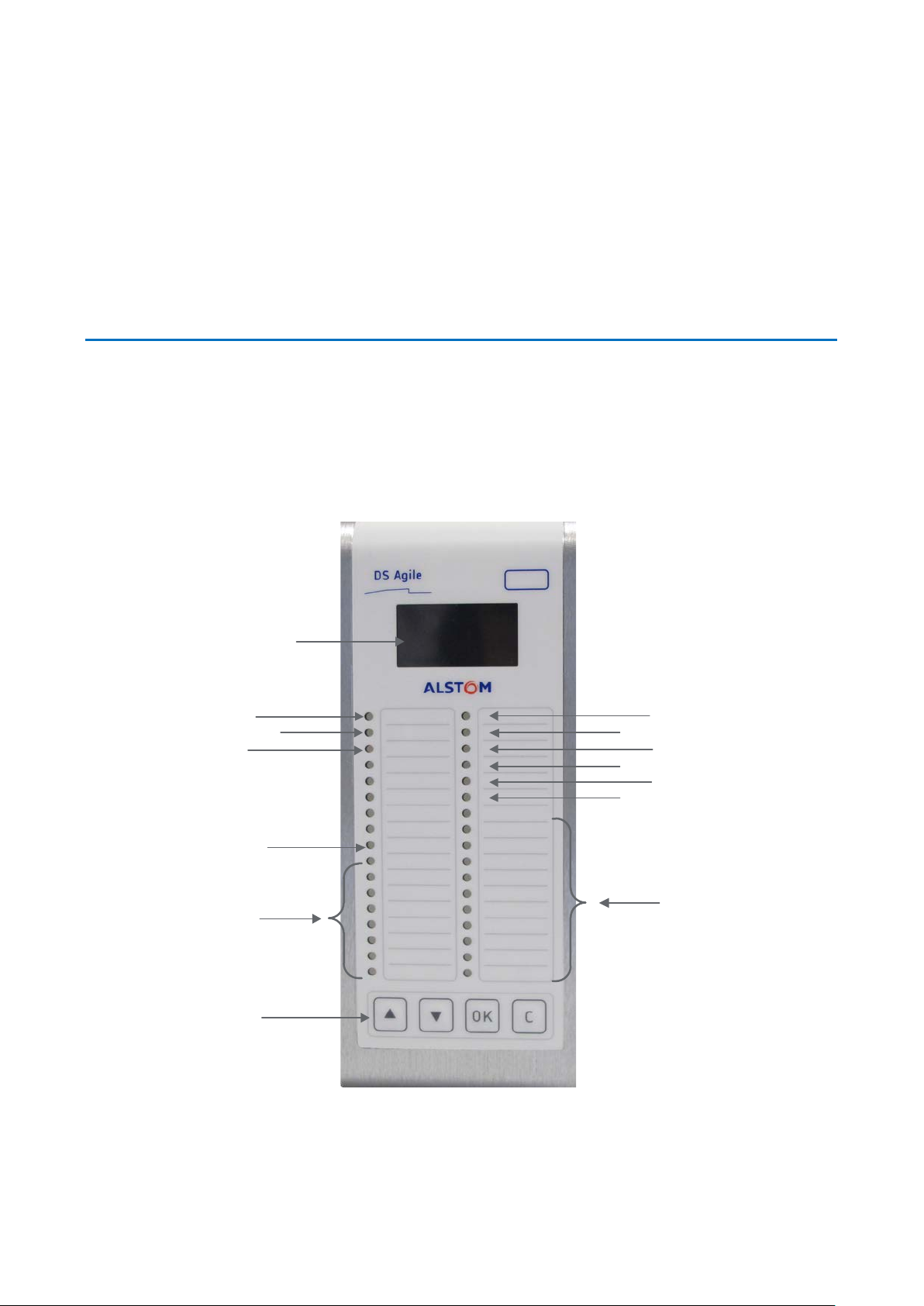
The following section show different views of the device together with its
components.
Figure 1: Front View and Rear View
Page 17

GE Reason H49
Technical Manual
H49/EN M/C22
17
1 LED (boot, ok, alarm)
The front panel of the Reason H49 switch contains the following items:
Item Description
Liquid crystal display (LCD) with 4 lines of 16 characters:
Line 1: Empty
A
B Navigation buttons to access and browse the device menu
Line 2: H49
Line 3: IP address (255.255.255.255)
Line 4: Empty
Reason H49 is configured through the web application user interface (detailed later in
this document) or using configuration file.
Signification of the LEDs
Light Emitting Diodes (LEDs) and alarm contacts indicate the status of the product
and its ports:
LED
rank
1
2
3
4 to 9
18
19
20
21
22
Signification Color Description Activity
Power
1 LED
Operating state
Time
Synchronization
1 LED
Port activity
6 LEDs
Alarm
1 LED
HSR RedBox
1 LED
PRP RedBox
1 LED
PRP-HSR Coupling
1 LED
HSR QuadBox
1 LED
Green Powered on
Off Switch is off
Amber
(default)
Green
Green PTP or NTP synchronization
Red
Green 1Gbits/s
Amber 100Mbits/s
Red
Red (default) Power redundancy alarm
Green
Green
Green
Green
As long as the CPU board has not
booted.
Healthy (board works, no contact
alarm)
No synchronization or Switch in
Grandmaster
Not forwarding (access violation,
wrong MAC address)
No traffic On
Signs of activity Blinking
Not plugged or disabled by
configuration
Off
Page 18
Technical Manual
GE Reason H49
18
H49/EN M/C22
Alternatively,
S1602ENa
Alarm
Relay
Slot A
Slot B
Slot C
4.1.2 Bottom view
LED
rank
23
*
Signification Color Description Activity
Standard Switch
1 LED
Green
Red, Green
and Amber
LED chaser
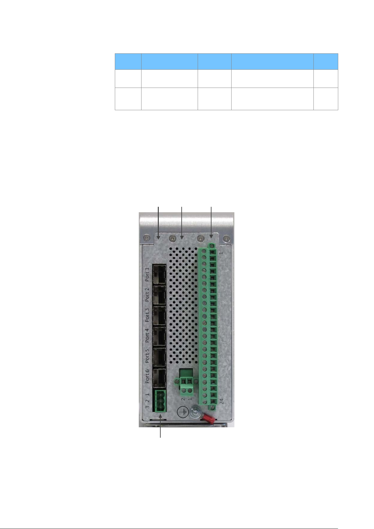
Reason H49 is a 6-port switch, supporting any combination of 100Mbps and 1Gbps
RJ45 copper or LC optical fiber ports.
The following figure presents the bottom view of the device together with its
components.
Figure 2: Reason H49 Bottom View
Page 19

GE Reason H49
Technical Manual
H49/EN M/C22
19
Multi-mode SFP transceivers are used for connections up to 2km, and single-mode
SFP transceivers can be used for distances up to 15km.
Description of the slots
Slot Board Description
Communication port
• Port 1 to port 6: SFP transceiver optical/copper
Alarm Relay Connector
A SRPV3
• Pin1: Normally Open
• Pin2: Common
• Pin3: Normally Closed
Secondary Power Supply
B BIU261D
• Pin2: In-
• Pin1: In+
Primary Power Supply
• Pin1 to Pin21: Not Connected
C BIU261D
• Pin22: Earth
• Pin23: In-
• Pin24: In+
Page 20
Technical Manual
GE Reason H49
20
H49/EN M/C22
DANP 3
H49
RedBox
DANP 2
SAN 1
SAN 4SAN 2
SAN 3
S1603ENa
LAN A Switch LAN B Switch
DANP 1
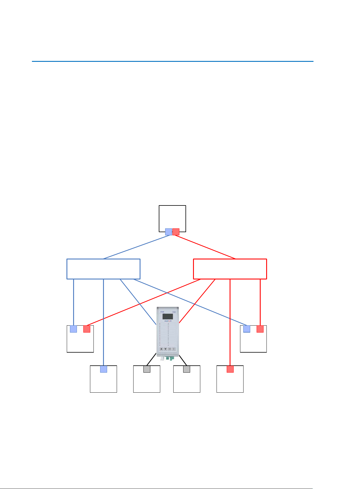
4.2 Parallel Redundancy Protocol (PRP)
The Parallel Redundancy Protocol (PRP) is implemented according to the definition in
the standard IEC 62439-3 (2016) Clause 4.
PRP allows seamless switchover and recovery in case of network disruption (for
instance cable, driver, switch or controller failure).
A PRP compatible device has two ports operating in parallel, each port being
connected to a separate local area network (LAN) segment. IEC 62439-3 (2016)
Clause 4 assigns the term DANP (Doubly Attached Node running PRP) to such
devices. Critical devices should be doubly attached using two ports. The two LANs
have no connection between them and are assumed to be fail-independent.
A source DANP sends the same frame over both LANs and a destination DANP
receives it from both LANs within a certain time, consumes the first frame and
discards the duplicate. In the following figure, DANP1 and DANP2 implement this
redundancy.
Figure 3: Example PRP Redundant Network
Singly Attached Nodes (SAN) are connected to only one LAN (see SAN 1 and SAN 4 in
previous figure) and they do not implement any redundancy. They can, however, be
Page 21

GE Reason H49
Technical Manual
H49/EN M/C22
21
DANP 2
DANP 1
SAN 1 SAN 4
SAN 3
S1604ENa
LAN A Switch LAN B Switch
H49 - RedBox
SAN 2
connected to both LANs, via the Reason H49 switch that converts a singly attached
node into a doubly attached node. It acts as a redundancy box or RedBox.
Devices with single network cards such as personal computers, printers, etc., are
singly attached nodes that may be connected into the PRP network via a RedBox as
shown in the following figure.
This is the case for SAN2 and SAN3. Because these SANs connect to both LANs, they
can be considered as Virtual Doubly Attached Nodes and described as VDANs.
Reason H49 can be configured as PRP RedBox and connect up to four SANs to the PRP
network as shown in the following figure:
Figure 4: Reason H49 connecting four SANs to the PRP Network
Page 22
Technical Manual
GE Reason H49
22
H49/EN M/C22
DANH 3
DANH 2
SAN 1
SAN 2
S1605ENa
"C" frame
from SAN
"D" frame
to SAN
"A" frame "B" frame
Returning "B" frame is stopped Returning "A" frame is stopped
“A” frames
“B” frames
non-HSR frames exchanged between ring and host
frame is removed from the ring by the node
H49
HSR RedBox
DANH 1
4.3 High-availability Seamless Redundancy (HSR) Protocol
The HSR protocol is implemented accordingly to IEC 62439-3 (2016) Clause 5.
HSR allows seamless communication in case of a single network disruption (for
instance cable, driver, switch or controller failure).
An HSR-compatible device has two ports operating simultaneously, both ports being
connected to the same LAN. IEC 62439-3 (2016) Clause 5 assigns the term DANH
(Doubly Attached Node running HSR) to such devices. Reason H49 is a DANH.
The figure below shows an example of an HSR network. The doubly attached nodes
HSR RedBox, DANH 1 and DANH 2 send and receive HSR frames in both directions,
while the singly attached nodes SAN 1 and SAN 2 can only send and receive frames
without HSR header.
Singly attached nodes can, however, be connected to HSR ring, via a device which
converts a singly attached node into a doubly attached node. Devices performing this
function are often referred to as redundancy boxes or RedBoxes. Thus, devices with
single network cards such as personal computers, printers, etc., are singly attached
nodes that may be connected to the HSR network via a RedBox as shown in the
figure.
Because these SANs are connected to the HSR network, they can be considered as
Virtual Doubly Attached Nodes and described as VDANs.
Figure 5: Example HSR Redundant Network
Page 23

GE Reason H49
Technical Manual
H49/EN M/C22
23
HSR is based on a ring-type architecture to achieve its network path redundancy.
Duplicate packets, identified as “A” and “B”, are sent in opposite directions of the ring
to achieve redundancy down to the packet level. When a packet arrives at a DANH
node, the node will determine if the packet is addressed to it or to another
destination.
• If the packet is addressed to the node, then
It will process it or
It will discard it if it is a duplicate packet
• If the packet is for another destination, then
If the DANH device receives a frame that it originally sent, it does not
forward it
Otherwise, it will simply forward the packet on to the next node in the
network.
Frames sent by a SAN device (see “C” frames in the following figure) are converted
into two “A” and “B” frames and sent over the HSR network.
Received frames that are addressed to a SAN managed by a Redbox (such as MMS
messages) are not forwarded on to the HSR network.
There are two basic operation principles, depending on whether the broadcasted
frames are multicast (e.g. GOOSE) or unicast (e.g. MMS reports).
• Multicast (e.g. GOOSE): A source DANH sends a frame over both ports (“A”-
frame and “B”-frame). The destination DANH receives, in a fault-free state, two
identical frames from each port within a certain interval, passes the first frame on
to its higher layers. A source DANH discards any duplicate multicast frame from
the ring.
• Unicast (e.g. REPORT): A destination node of a unicast frame does not forward a
frame for which it is the only destination. It removes the unicast frame from the
ring.
Page 24

Technical Manual
GE Reason H49
24
H49/EN M/C22
DANH
S1606ENa
DANH
DANH DANH
H49
QuadBox
H49
QuadBox
DANH
DANH
DANH
DANH
DANH
"A"
"B"
Source
Destination
“A” frames
“B” frames
frame is removed from the ring by the node
4.4 HSR Quadbox
It is possible to connect two HSR rings when the traffic flow exceeds the capabilities
of a single ring. However, transmission delays from end to end are not improved. This
connection is possible thanks to quadruple port devices with forwarding capabilities
called QuadBoxes as shown in the following figure.
Although one QuadBox is sufficient to forward traffic, two QuadBoxes are used to
prevent a single point of failure. A QuadBox forwards frames over each ring as any
HSR node, and passes the frames unchanged to the other ring, except if the frame can
be identified as a frame not to be forwarded to the other ring. To this effect, a
QuadBox is expected to filter traffic based for instance on multicast filtering or on
VLAN filtering. There is no learning of MAC addresses in a QuadBox, though, since the
learning of MAC addresses on specific ports of a QuadBox device could lead to a short
break in communication if the QuadBox that has learned an address and is
forwarding network traffic fails.
With QuadBoxes realized as single physical entities, the two interconnected rings
share the same redundancy domain concerning fault tolerance. If one QuadBox
breaks down, both interconnected rings are in a degraded state and cannot tolerate a
further fault.
Figure 6: Two QuadBoxes linking two HSR Rings
The presence of two QuadBoxes on the same ring causes that two copies of the same
frame are transferred from the first ring to the second, each generating other two
copies.
This does not cause four frames to circulate on the second ring, since, when a copy
from a first QuadBox reaches the second QuadBox on the same second ring, the
second QuadBox will not forward it if it already sent a copy that came from its
interlink.
Page 25

GE Reason H49
Technical Manual
H49/EN M/C22
25
Conversely, if the second QuadBox did not yet receive a copy from its interlink, it will
forward the frame, but not the copy that comes later from the interlink.
When a QuadBox receives a frame that it itself injected into the ring or a frame that
the other QuadBox inserted into the ring, it forwards it to the interlink and to its other
port if it did not already send a copy. This duplicate will be discarded at the other end
of the interlink. This scheme may cause some additional traffic on the interlink, but it
allows to simplify the design of the logic.
Note:
The maximum time skew between two frames of a pair is about the same as if all nodes were on the same ring
Page 26
Technical Manual
GE Reason H49
26
H49/EN M/C22
DANH
S1607ENa
DANH DANH DANH
"A"
"B"
H49
RedBox
“A“
Destination
LAN A
LAN B
"AB"
"BA"
DANP
DANP
Source
“A” frames
“B” frames
duplicated redundant frames
frame is removed from the ring by the node
DANH
H49
RedBox
“B“
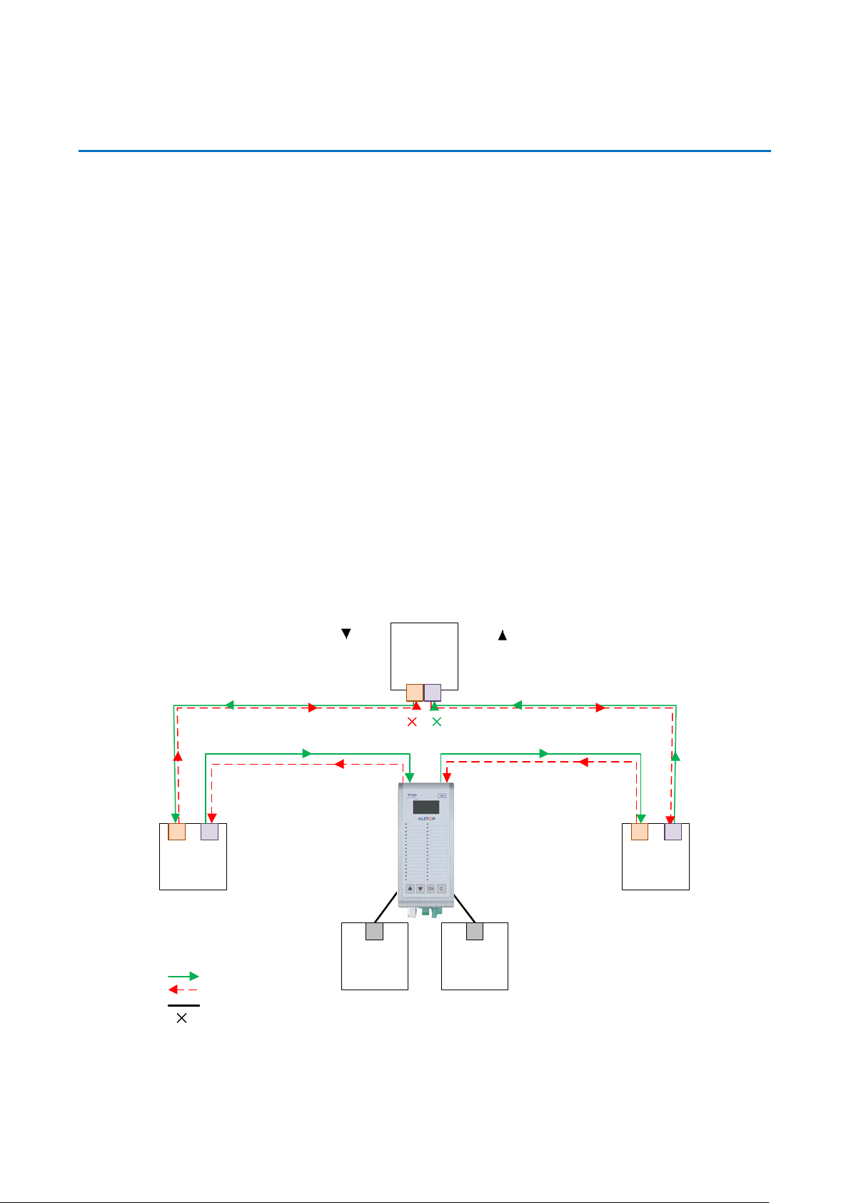
4.5 PRP-HSR Coupling
A HSR may be coupled to a PRP network through two RedBoxes, one for each LAN as
shown in the figure here below. In this case, the RedBoxes are configured to support
PRP traffic on the interlink and HSR traffic on the ring ports.
The sequence number from the PRP RCT is reused for the HSR tag and vice versa, to
allow frame identification from one network to the other and to identify pairs and
duplicates on the HSR ring, introduced by a twofold injection into the ring through the
two HSR RedBoxes.
Figure 7: Coupling two PRP LANs to an SRS Ring
Page 27
GE Reason H49
Technical Manual
H49/EN M/C22
27
DANH
S1608ENa
DANH
DANH
DANH DANH
"B"
Destination
LAN A
LAN B
"BA"
DANP
DANP
Source
“A” frames
“B” frames
duplicated redundant frames
frame is removed from the ring by the node
"A"
"AB"
H49
RedBox
“A“
H49
RedBox
“B“
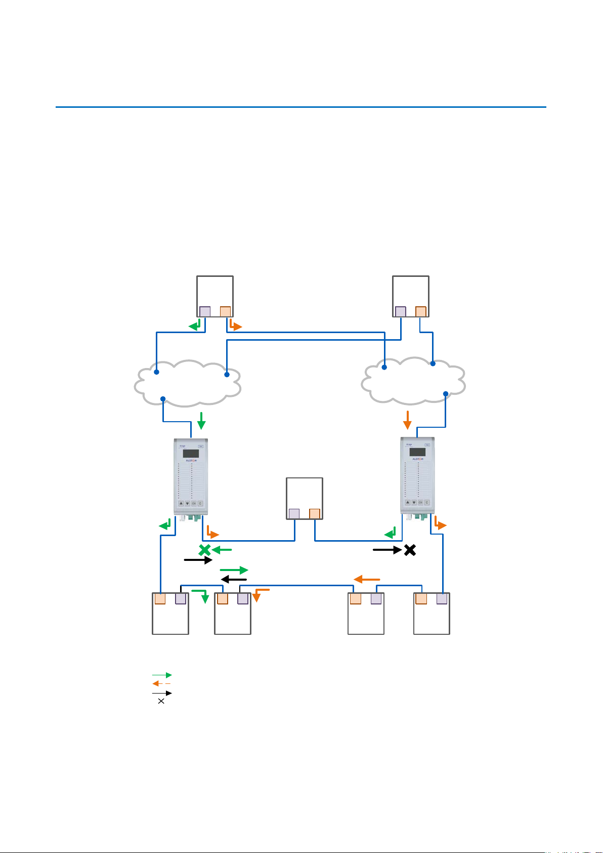
The HSR RedBoxes for connecting the ring to a PRP network operate identically to
those used to attach SANs, except that they are configured as RedBox “A” or RedBox
“B” to accept PRP frames on their interlink. In the figure here above, RedBox A and
RedBox B would send the same frame (A and AB, respectively B and BA), but if a
RedBox receives the frame before it could send it itself, it refrains from sending it.
In the figure here above, RedBox A will not generate an “A“ frame on behalf of LAN A if
it previously received the same frame as “AB“ from the ring, or conversely, RedBox “B”
will generate an “AB” frame if it did not previously receive an “A” frame from the ring,
which is the case whenever frame “A” is not a multicast frame.
Multicast frames or unicast frames without a receiver in the ring (see figure here
above) are removed by the RedBox that inserted them into the ring, if they originated
from outside the ring.
The following figure shows the same coupling when the source is within the ring.
Figure 8: Coupling an HSR Ring to two PRP LANs
Page 28
Technical Manual
GE Reason H49
28
H49/EN M/C22
DANH
S1609ENa
DANH DANH
DANH
H49
RedBox
“1A“
LAN A
LAN B
H49
RedBox
“1B“
DANP
DANP
DANH DANH
DANH DANH
H49
RedBox
“2A“
LAN A
LAN B
H49
RedBox
“2B“
DANP
DANP
DANH DANH
To avoid reinjecting a frame into the PRP network through the other RedBox, each
HSR frame carries the identifier of the PRP network from which the frame came
originally. Therefore, RedBoxes are to be configured with the NetId of the PRP
network to which they are attached.
Other combinations of PRP and HSR networks are allowed. Some of them are
explained in the following sections.
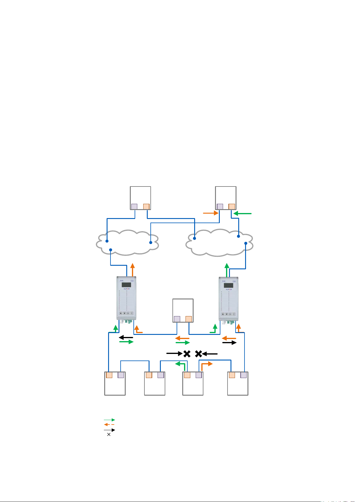
4.5.1 Connecting several PRP Networks to an HSR Ring
Up to six PRP networks can be connected to the same HSR ring, each being identified
by a 3- bit NetId.
The two RedBoxes that connect a PRP network with an HSR ring are configured with
the NetId (1..7) and the LanId (A=0/B=1), see the following figure.
Figure 9: Coupling one HSR ring to several PRP Networks
To prevent reinjection of frames coming from one PRP network into another PRP
network or from the same, a RedBox only forwards from the HSR ring frames that do
not carry its own NetId. When inserting into the ring a PRP frame from LAN A or from
LAN B of a PRP network with a given NetId, a RedBox inserts into the PathId of the
HSR tag its own NetId and the LanId, i.e. one of “2”/”3”, “4”/”5”, “6”/”7”, “8”/”9”, “A”/”B”,
“C”/”D” or “E”/”F”, depending if it is RedBox A or B.
Page 29

GE Reason H49
Technical Manual
H49/EN M/C22
29
DANH
S1610ENa
DANH
DANH
DANH DANH
H49
RedBox
“A“
LAN A
LAN B
H49
RedBox
“B“
DANP
DANP
Source
DANH DANH
DANH
DANH DANH
H49
RedBox
“A“
H49
RedBox
“B“
Source
Ring A Ring B
Conversely, when forwarding a frame from the ring to a PRP network, a RedBox insert
the LanId “A” or ”B” into the RCT, depending if it is RedBox A or RedBox B.
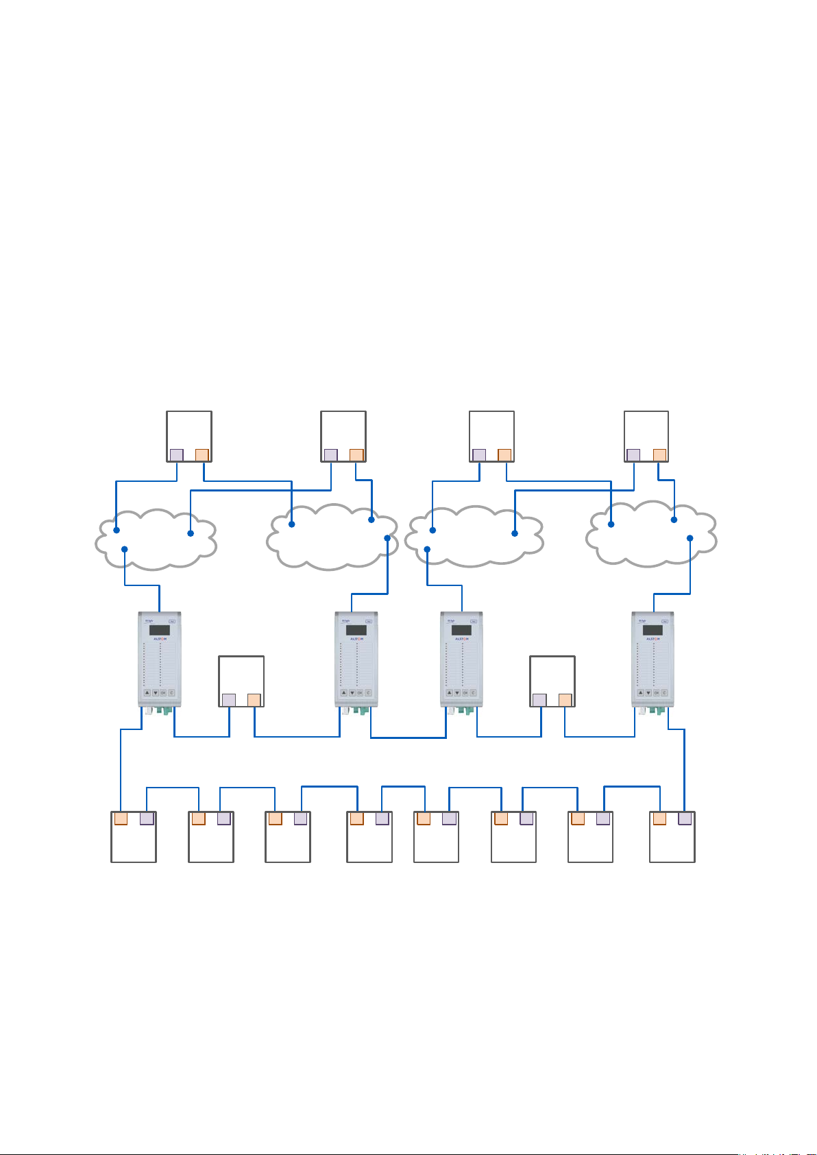
4.5.2 Connecting one PRP Networks to several HSR Rings
A PRP network can be connected to any number of HSR rings, but these rings cannot
be connected between themselves, neither by QuadBoxes nor by another PRP
network since this would create loops.
Figure 10: Coupling Several HSR Rings to a PRP Network
Page 30

Technical Manual
GE Reason H49
30
H49/EN M/C22
4.6 Standard Switch
Reason H49 can be configured as a standard Ethernet Switch. In this case, it manages
up to six Ethernet ports.
Reason H49 using auto-negotiation:
• Automatically determines the speed of transmission on the 10/100/1000 Base
ports according to the following standards:
IEEE 802.3u – 100BaseTX, 100BaseFX
IEEE 802.3ab – 1000BaseTX
IEEE 802.3z – 1000BaseLX, 1000BaseSX
• Determines whether communication is half-duplex or full-duplex, and adapts
accordingly.
Addressing:
• Each Ethernet device inserts its unique “MAC address” into each message it
sends.
• The receiving port automatically recognizes the MAC address in a received frame
and stores it.
• Once an address is recognized and stored, the switch will forward frames to the
appropriate port.
• Up to 512 MAC addresses can be stored and monitored at any time.
4.7 Time Synchronization
Reason H49 supports real-time clock synchronization for the timestamp of logs or
events through the following network protocols:
• Precision Time Protocol (PTP in accordance with IEEE/IEC 61588 (2009))
• Network Time Protocol (NTP).
Note:
The Reason H49 switch does not support Spanning Tree Protocol (STP, RSTP, MSTP).
The time protocol used is independent of the network architecture (HSR or PRP).
Thus, the time server can be placed in either the HSR ring or one of the PRP LANs.
It is important to emphasize that the time server shall be placed in a VDAN device; in
other words, it shall be linked to the network through a RedBox.
Page 31

GE Reason H49
Technical Manual
H49/EN M/C22
31
4.7.1 Precision time synchronization (PTP)
Time synchronization from a master clock synchronized to the global positioning
satellite (GPS) system is accepted over the network according to IEEE/IEC61588 Ed.2.
(2009).
PTP synchronizes all clocks within a network by adjusting distributed clocks to a
grandmaster clock. PTP enables distributed clocks to be synchronized and maintained
to sub-microsecond accuracy.
Note:
On PTP protocol, a time discrepancy of 60 milliseconds per 24h is reported on Reason H49 (equipped with a SRPv3 version x) and
used as Master Clock (M1) (case VDAN-P Grandmaster Clock not available).
Figure 11: Example of PRP/HSR Architecture with the Precision Time Protocol (PTP)
Page 32

Technical Manual
GE Reason H49
32
H49/EN M/C22
4.7.2 NTP time synchronization
Network Time Protocol (NTP) is a networking protocol for clock synchronization
between computer systems over packet-switched, variable-latency data networks.
Reason H49 supports NTP as shown in the figure below.
4.7.2.1 Time Zone
Figure 12: Example of NTP Synchronization
The internal clock of Reason H49 can be synchronized using NTP protocol, which
sends the UTC time (Greenwich Mean Time). When using the equipment in other
regions, the time zone may be set manually to correct the internal clock.
Page 33

GE Reason H49
Technical Manual
H49/EN M/C22
33
4.8 SNMP
Simple Network Management Protocol (SNMP) is the network protocol developed to
manage devices on an IP network.
To exchange information, SNMP relies on a Management Information Base (MIB)
that contains information about parameters to supervise. A MIB format is a tree
structure, with each node identified by a numerical Object Identifier (OID). Each OID
identifies a variable that can be read or set via SMP with the appropriate software.
4.8.1 Supported MIB
The SNMP MIB consists of distinct OIDs, each of which refers to a defined collection of
specific information used to manage devices over the network.
GE Grid Solutions management information bases (MIB) use the following types of
object identifiers (OID):
• BRIDGE-MIB (RFC 1493)
• SNMPv2-MIB (RFC 1907)
• TCP-MIB (RFC 2012)
• UDP-MIB (RFC 2013)
• SNMPv2-SMI (RFC 2578)
• SNMPv2-TC (RFC 2579)
• RMON-MIB (RFC 2819)
• IF-MIB (RFC 2863)
• PRP/HSR MIB (IEC 62439-3)
• Power Profile MIB (IEEE C37.238)
Page 34

Technical Manual
GE Reason H49
34
H49/EN M/C22
4.8.2 SNMP Traps
The SNMP agent in the Reason H49 switch can send SNMP traps to the management
station. Traps are change-of-state messages alerting the SNMP manager to a
condition on the network. A trap message is sent to alert the management station to
some event or condition on the switch such as:
• Loss of communication on one port
• Loss of power supply input
• Loss of time synchronization (PTP)
• Resource exhaustion
Page 35

GE Reason H49
Technical Manual
H49/EN M/C22
35
5.1 Dimensions
Chapter 5: Installation
Figure 13: Front Face and side with dimensions
Page 36

Technical Manual
GE Reason H49
36
H49/EN M/C22
S1616ENa
Manufacturer Label Firmware Label Manufacturing Label
5.2 Device Labeling
The figure below shows an example of the standard labels stuck to the Reason H49
switch:
Figure 14: Example of Device Labeling
Main information present in these labels includes:
• Company
• Product name
• Cortec code
• Voltage range
• Serial number
• Caution notice
• Firmware version
• MAC address
The following tables give the details of the label components.
Page 37

GE Reason H49
Technical Manual
H49/EN M/C22
37
5.2.1 Manufacturing Label
Figure 15: Manufacturing Label
Label 20x94mm
Diagram number:
Reference of the product: GP0067001
Version of the product: B
Serial number:
Unique serial number: 8 numerical digits: 11111158
Date of manufacturing /MM/YY: /06/16
Barcode content description:
Cortec number: DSAGILEH4900000000000B
Serial number without the manufacturing date: 11111158
MAC Address: 80B32AFF0000
Label1 - Manufacturing Label
GP0067001_B
11111158/06/16
DSAGILEH4900000000000B_11111158_80B32AFF0000
Page 38

Technical Manual
GE Reason H49
38
H49/EN M/C22
5.2.2 Firmware Label
Label 10x27mm
Firmware version:
Name of the product: H49
First digit: Major functional version (2)
Second digit: Compatibility indicator version (0)
Third digit: Maintenance/Evolution/Bug fix version (0)
Fourth digit: Second level maintenance version (0)
Figure 16: Firmware Label
Label2 - Firmware Label
H49_2.0.0.0
Note:
Firmware label is given as an example. Check last issue of datapack for correct firmware label.
5.2.3 Manufacturer Label
Figure 17: Manufacturer Label
Label3 - Manufacturer Label
Label 28x50mm
Font: Alstom regular, black
Content: manufacturer contact information
Page 39

GE Reason H49
Technical Manual
H49/EN M/C22
39
5.3 Mounting
Reason H49 is designed to be mounted vertically on a standard DIN Rail.
For this purpose, two adjustable mounting brackets are located on the back of the
H49, one at the top and one at the bottom of the rear face as shown below:
Figure 18: H49 DIN Rail Mounting Details - Rear View with Mounting Rack
Optional Weidmuller FM4 TS35 mounting clip can also be used, as shown in the
following figure (to be ordered separately).
Figure 19: H49 DIN Rail Mounting Details - Rear View with Weidmuller Clip
Page 40

Technical Manual
GE Reason H49
40
H49/EN M/C22
5.3.1 Recommendations for Electromagnetic compatibility
Caution:
Reason H49 operates within -25°C/+55°C in normal conditions. As heat
within Reason H49 switches is channeled to the enclosure, it is
recommended that 1,5 cm of space be kept between each switch mounted
within the DIN Rail to allow for a small amount of airflow.
A closer spacing will result in higher device operating temperature.
Caution:
The orientation in which the Reason H49 is fitted on the DIN Rail is a key
factor to optimal performance. Reason H49 requires to be installed
vertically on the DIN rail. Other position would lead to inadequate
ventilation and result in increased heat generation.
Page 41

GE Reason H49
Technical Manual
H49/EN M/C22
41
Chapter 6: Connection
As well as connections to the Ethernet network, Reason H49 requires auxiliary power
supply connection and safety earth connection. Alarm outputs are provided and
these should be connected for system supervision.
The locations of the various connection points are detailed section Bottom view.
6.1 General Wiring
Only two wires can be screwed together on any one connector. The AC and DC signal
and communication wires should use separate shielded cable.
Wires should be connected with the power supply connectors unplugged. Each wired
signal has to be tested before plugging and fixing the connectors. The connectors
have to be fixed on the H49 case with the screws available at each extremity of the
connector.
Caution:
A high rupture capacity (HRC) fuse must be used for auxiliary supplies (for
example Red Spot type NIT or TIA) with the following characteristics:
• Current rating: 16 Amps
• Minimum dc rating: 220 V dc
• gG operating class in accordance with IEC 60269
The fuses must be connected in series with the positive auxiliary supply input
connections for both primary (Pin 23) and secondary (Pin 1) BIU261D inputs.
For connection of the protective (earth) conductor, refer to chapter 6.2 Earth Wiring
page 42.
6.1.1 Well-organized Wiring
Caution:
Improperly installed cabling can affect device performance and generate
interferences.
To avoid interferences, careful placement of cables is required. The principle
consists in physically separating power sources (AC/DC) and communications
cables (i.e. high voltage from RJ45/Copper). This is even more important
when devices receive time synchronization from PTP master clock.
Whenever possible, use cableways or troughs.
Page 42

Technical Manual
GE Reason H49
42
H49/EN M/C22
6.2 Earth Wiring
6.2.1 Protective Earth Wiring
This equipment requires a protective conductor (earth) to ensure user safety
according to the definition in the standard IEC 60255-27: 2005 Insulation Class 1.
Warning:
– To preserve the device's safety features, the protective conductor (earth)
MUST not BE disturbed when connecting or disconnecting functional earth
conductors, such as cable screens, to the PCT stud.
– The protective conductor must be connected first, in such a way that it is
unlikely to be loosened or removed during installation, commissioning or
maintenance. This MAY be achieved by use of an additional locking nut.
Caution:
Always place the protective conductor (earth) as shown on the diagram
below.
Figure 20: Protective Earth Screw
The protective conductor (earth) must be as short as possible, with low impedance.
The best electrical conductivity must be maintained at all times, particularly the
contact resistance of the plated steel stud surface.
Page 43

GE Reason H49
Technical Manual
H49/EN M/C22
43
C0047ENb
Good conductor surface
Cable crimp
Copper cable
minimum section: 2.5mm²
S1645
ENa
1,
5 cm
1,
5 cm
1,
5 cm
1,
5 cm
Figure 21: Example of Earth Cable
6.2.2 Casing / Earth Interconnection
To protect against disturbances, each Reason H49 must be carefully and correctly
interconnected.
Within Reason H49 equipment, earth and casing must be connected to a grid-like
grounding system in the shortest possible way using low impedance (at high
frequencies), wide and short electrical connections (wires or braids) as specified in
the IEC 61000-5 standard.
Figure 22: Recommended mounting and Casing / Earth interconnection
Page 44

Technical Manual
GE Reason H49
44
H49/EN M/C22
S1613ENa
6.3 Power Supply Wiring
Reason H49 contains a Basic Interface Unit (BIU261D) board, which includes two
redundant power supply inputs, as shown in the following figure:
Figure 23: Reason H49 Power Supply Wiring
BIU261D primary power supply
The primary power supply is connected using a 24-way connector block:
Figure 24: Typical 24-way Female Connector
Page 45

GE Reason H49
Technical Manual
H49/EN M/C22
45
BIU261D primary power supply
Pin n° Description
1 to 21 Not used
22 Voltage input: GND
23 Voltage input: AC/DC ( + )
24 Voltage input: AC/DC ( - )
Note:
Inputs must be connected to the specified pins. Other pins must remain unused and no other connection has to be made.
The 24-way connector block characteristics are as follows:
• Continuous rating 10A
• Connection method M3 screws
• Cable section 2.5mm2
• Connection pitch 5.08mm
• Insulation between terminals and to the earth 300 V basic insulation
• Standards UL, CSA
Note:
The connector is fixed using 2 M3 screws located at each end of the connector.
BIU261D secondary power supply
The secondary power supply is connected using a 2-way connector block:
Figure 25: Typical 2-way Female Connector
1 Voltage input: DC ( + )
2 Voltage input: DC ( - )
Pin n° Description
Page 46

Technical Manual
GE Reason H49
46
H49/EN M/C22
The 2-way connector block characteristics are as follows:
• Continuous rating 10A
• Connection method M2.5 screws
• Cable section 2.5mm2
• Connection pitch 5.08mm
• Insulation between terminals and to the earth 300 V basic insulation
• Standards UL, CSA
If the primary power supply input is lost while being used, the BIU261D switches to
the secondary power supply input. It will switch back to the primary power supply
when the latter becomes available again and has been stable for a few seconds.
If the secondary power supply is lost while being used, the BIU261 instantly switches
to the primary power supply. It will continue to use the primary power supply source
as long as it is available, even when the secondary power supply becomes available
again.
Reason H49 supports the following power supply use cases:
Primary source Secondary source
Use case 1 DC DC
Use case 2 DC OFF
Use case 3 OFF DC
Use case 4 AC DC
Use case 5 AC OFF
Nominal Power supply range
85Vac to 230Vac
85Vdc 220Vdc
85Vdc 220Vdc
Page 47

GE Reason H49
Technical Manual
H49/EN M/C22
47
S1351ENa
6.4 Alarm Relay Wiring
The 3-pin connector of the relay alarm on the SRPV3 board allows the following H49
statuses:
Figure 26: Relay Alarm Wiring
Pin Signal Description
1 Normally Open
2 Common
3 Normally Closed
Closed=Normal Operation
Open= Power supply defect (both input voltage sources are
down) / Operating System defect (Kernel crash, processor
overload, memory leak)
Closed= Power supply defect (both input voltage sources are
down) / Operating System defect (Kernel crash, processor
overload, memory leak)
Open= Normal Operation
6.4.1 Using Terminal Blocks
Printed-circuit board connectors can be used:
Figure 27: Pluggable Terminal Block
The relay alarm connector shall be plugged with MSTB 2,5 HC/ 3-ST-5,08 - 1911978
manufactured by Phoenix Contact.
6.4.1.1 Recommended Wire Size
The minimum recommended wire size for terminal blocks is 2.5mm2.
Page 48

Technical Manual
GE Reason H49
48
H49/EN M/C22
6.4.1.2 Crimped Ferrule
For safety reasons, wire terminations must be insulated using an insulated crimped
ferrule, suitable for 2,5mm
2
wire size.
Figure 28: Pluggable Terminal Block
Insulated wire ferrules must be slipped over the stripped cable and crimped to
prevent stranded wire from fraying.
Caution:
Refer to section 10.5.3 Auxiliary Fault Relays (Optical Port Alarm) page 128 for
electrical characteristics of alarm circuit.
Page 49

GE Reason H49
Technical Manual
H49/EN M/C22
49
S1353ENa
6.5 Ethernet Connections
Reason H49 is easy to install and operate. It is designed to work in an electrical plant
environment and it is fully certified IEEE 1613 series, IEC 61850-3 and IEC 60255-27.
Reason H49 connects to the network through a Small Form-factor Pluggable module
(SFP), which can be inserted and removed safely while the switch is powered and
operating:
Figure 29: SFP Module Connection
The SFP module is a hot-swappable connector that provides high-speed performance.
Reason H49 supports two kinds of modules:
• Optical LC-type SFP
• RJ45-type SFP.
The table below lists the supported LC-type SFP and references:
Reference Manufacturer Description Connector Type Image
AFBR-5715ALZ fit-foxconn
HFBR-57E0APZ AVAGO
1Gbps Multimode
850nm wavelength
100Mbps Multimode
1300 nm wavelength
LC Duplex
LC Duplex
100Mbps Single-mode SR
AFCT-5765ALZ fit-foxconn
(up to 2 km)
1300 nm wavelength
LC Duplex
Page 50

Technical Manual
GE Reason H49
50
H49/EN M/C22
mode (up to
Reference Manufacturer Description Connector Type Image
1Gbps Single-
AFCT-5715ALZ fit-foxconn
AFCT-5765ATLZ fit-foxconn
10km)
1310 nm wavelength
100Mbps Single-mode IR1 (up to 15 km)
1300 nm wavelength
LC Duplex
LC Duplex
The table below lists the supported RJ45-type SFP and references:
Reference Manufacturer Description
ABCU-5741ARZ fit-foxconn 10/100/1000Mbps RJ45
Connector
Caution:
Reason H49 is delivered with SFP cap inserted in each SFP
cage.
The cap must be inserted in each SFP cage unused. It is a
protection against dust.
Type
Image
Page 51

GE Reason H49
Technical Manual
H49/EN M/C22
51
6.5.1 RJ45-Type Connection
S1355ENa
The following figure shows the RJ45-type module used by the Reason H49 switch and
its corresponding RJ45 connector.
Insulated cable category 6 or 5e (FTP: Foil Twisted Pair) or insulated (STP – Shielded
Twisted Pair) with RJ45 connectors are mandatory.
Note: Do not use RJ45 UTP cable. This kind of cable may disrupt time synchronization.
Figure 30: RJ45 SFP Module
Caution:
When SFP Copper Ethernet modules are used, the connected cables shall
be shortened to minimum possible length. We recommend that cables
(such as RJ45 category 6 or 5e) do not exceed 3 meters to comply with
Electromagnetic compatibility (EMC) requirements.
Connected cables shall not extend beyond the cabinet where the product
is used. The equipment connected to both ends of the cable shall be
connected directly to a common protective earth point within the same
cabinet.
Page 52

Technical Manual
GE Reason H49
52
H49/EN M/C22
6.5.2 Optical LC-type Connections
S1354ENa
The following figure shows the optical LC-type module used by the Reason H49
switch and its corresponding LC-type connector.
Figure 31: Ethernet Fiber Optic – LC-type Module
Warning about Laser Rays
Caution:
NEVER look into optical fibers. Always use optical power meters to
determine operation or signal level.
Non–observance of this rule could possibly result in personal injury.
Signals transmitted via optical fibers are unaffected by interference. The
fibers guarantee electrical isolation between the connections.
If electrical to optical converters are used, they must have management of
character idle state capability (for when the fiber optic cable interface is
"Light off").
-type small form-factor pluggable (SFP) modules shall be used. LC/ST or LC/SC
LC
optical patch cords may be used to connect the board to devices fitted with ST or SC
connectors.
Figure 32: Example of Optical Patch Cord (Multimode Duplex LC/ST)
Page 53

GE Reason H49
Technical Manual
H49/EN M/C22
53
6.6 Fiber Optic Budget Calculations
Transmitted Power
Received Power
S0525ENb
Optical
Transmitter
Optical loss:
Connectors, fibers
Optical Receiver
Optical power is expressed in Watts. However, the common unit of power
measurement is the dBm, defined by the following equation: Power (dBm) = 10 log
Power (mW) / 1 mW.
The fiber optic budget is the difference between the power emitted into the fiber and
the sensitivity (minimum amount of power required) of the receiver connected
through the fiber optic cable.
Link Power Budget = Transmitter Power (dBm) - Receiver Sensitivity (dBm). The
distance over which the signals can be transmitted and successfully received is
affected by the optical loss as shown in the figure below.
Figure 33: Fiber Budget
For this product, the optical budget is given in the table below.
Fiber type
Power coupled into fiber -19 dBm -15 dBm
Sensitivity -31 dBm -34 dBm
In calculating the maximum distance, the following figures can be used as a guide, but
you should check with your supplier for precise figures.
Fiber type Multimode Single mode
Link budget 12 dB 19 dB
Typical connector loss
(1 per receiver, 1 per transmitter)
Safety Margin 4 dB 4 dB
Allowed link attenuation 6.4 dB 13.4 dB
Typical cable attenuation 1 dB/km 0.4 dB/km
Maximum range 2 km 15 km
Insertion of a patch panel (per panel) 2 dB 1 db
Multimode
62.5/125 micron
0.8 dB 0.8 dB
Single mode
9/125 micron
Page 54

Technical Manual
GE Reason H49
54
H49/EN M/C22
6.7 Power up
During the power up process the following indicators are displayed:
• LED 1 is green
• LED 2 is amber
• LED 18 indicates the state of the redundant power supply
At the end of the power-up process, the following indicators are displayed:
• The LCD screen displays “H49” and the device’s IP address
• LED 1 is green
• LED 2 is green
Refer to section 4.1.1 Front Panel page 16 for LEDs indications.
Page 55

GE Reason H49
Technical Manual
H49/EN M/C22
55
Chapter 7: Settings
To take full advantage of all the features available from the Reason H49 switch, the
device must properly be configured for your network.
There are several ways to configure the Reason H49 switch:
• A web user interface, accessible via the switch’s built-in web server.
• An SNMP interface can be used to read/write some settings
• CLI (command Line Interface) can be used to read/write most settings (SSH).
Note:
This chapter only explains how to configure the Reason H49 switch through the embedded web server. However, an appendix, at
the end of this document, describes the command lines supported by the SSH service.
7.1 Connecting to Reason H49
To access the embedded web server from a PC connected to the same LAN as the
Reason H49 switch, the PC and the H49 must be on the same subnet.
The default IP address of the Reason H49 switch is 192.168.254.254 and the sub
mask is 255.255.0.0.
Your PC IP address must be set in the same LAN for initial configuration.
Note:
The device connects to the network through a Small Form-factor Pluggable module (SFP). Refer to the Ethernet Connections
section to see the references of the supported RJ45-type SFP module.
7.2 Accessing the Web User Interface
The H49 web user interface provides an easy way to modify the switch’s configuration
settings and access the built-in network and security administration functions.
The web user interface can be accessed via a web browser.
Once your PC is connected to the same LAN and subnet as the H49, open the switch’s
web user interface as follows:
1 Open one of the following recommended web browsers:
Page 56

Technical Manual
GE Reason H49
56
H49/EN M/C22
Browser name Manufacturer
Chrome Google
Internet Explorer Microsoft
Mozilla Firefox
Safari Apple Inc.
n the web browser’s address bar, type the default H49’s IP address:
2 I
Mozilla Foundation
Mozilla Corporation
192.168.254.254 and press Enter on your keyboard.
Note:
The embedded web server only supports the secure HTTPS protocol. When you access the server via https, you may see a
warning dialogue indicating that the certificate was signed by an unknown authority. This is expected as the certificate provided
by default is self-signed. To avoid this message in the future, you can choose to install a properly signed certificate.
Page 57

GE Reason H49
Technical Manual
H49/EN M/C22
57
7.3 Logging In
The web login window prompts you for a login name and password.
Use the following default values:
• Login: user
• Password: user
Note: See the Cyber Security section for more information on user accounts.
If an error occurs during the authentication process, an information message appears
on screen, as shown in the following figure.
Figure 34: Reason H49 Web User Interface - Error during Login Process
When connecting to Reason H49 for the first time, the system prompts the user to
change the default password.
• Enter a new password and confirm.
Note:
The new password must match the Password complexity parameter, which is enabled by default in H49 web user
interface. Refer to section 8.1.5 Password Management, page 108 for more information.
Upon successful authentication, the user is granted authorization for access.
Read the Software License agreement and click Yes to agree to the terms:
Figure 35: Reason H49 Web User Interface - Agreement Conditions
Page 58

Technical Manual
GE Reason H49
58
H49/EN M/C22
7.4 Feature Overview
The embedded web user interface consists of two areas:
• A configuration menu, on the left side of the window, which is organized into
three main sections;
System
Network
Security
• A setting panel, on the right.
Navigate through the configuration menu to access each of the switch’s functions.
Figure 36: Reason H49 Web User Interface – Start Page
Page 59

GE Reason H49
Technical Manual
H49/EN M/C22
59
7.4.1 System
7.4.1.1 Status
The System section provides the current configuration of the Reason H49 switch
together with its status.
It also allows the user to update the main system attributes.
To get the global status of the Reason H49 switch, click Status in the System
section:
The top part of the page shows the following information:
Attribute Description
Redundancy mode Selected redundancy mode
IP address Device’s IP address
MAC address Device’s MAC address
Date & Time Device’s clock date and time
Uptime Elapsed time since last reboot
Firmware Version Version of the firmware currently running on the device
L
ED Chaser
The LED chaser of the H49 is a function used to identify correctly a given device
amongst others.
It consists in sequentially lighting all the LEDs in the front panel one after the other,
eight at a time.
• Click Enable LED Chaser to activate the LED chaser and make the device’s LEDs
b
link in sequence.
• Click again to stop the LED chaser (Disable LED Chaser button), or press the “C”
button on the device front panel.
Alternatively, the LED chaser can be stopped by pressing the “C” button in the front
panel.
Supply Status
This area shows information about the input voltage sources (Primary voltage
source/Secondary voltage source):
Figure 37: H49 Web User Interface – Power Supply Status
Page 60

Technical Manual
GE Reason H49
60
H49/EN M/C22
Interfaces
This area displays the interface status:
Figure 38: H49 Web User Interface – Interfaces Status
Note:
The interface configuration is done in the System > Redundancy Mode page.
Each interface has a colored button and some details:
Attribute Description
Display the port type in accordance of colors.
• Red: Redundant interface Port A
• Green: Redundant interface Port B
Button color
• Blue: PRP coupling interface
• White: Standard interface
• Grey: The port is not available in the selected redundancy mode.
• Copper 10/100/1000 Mbps
Media and speed state
of interfaces X1 to X6
• Fiber 100 Mbps
• Fiber 1000 Mbps
• Green: Connected
Connection state of
interfaces X1 to X6
• Yellow: Disconnected
• Red: Disabled
These settings can be modified in the Network > Interface page.
Page 61

GE Reason H49
Technical Manual
H49/EN M/C22
61
Click a connected interface to get the status of the packets sent:
Figure 39: H49 Web User Interface – Statistics of a Connected Interface
Time Synchronization
This area displays read-only information about the device’s time synchronization
protocol.
Figure 40: Reason H49 Web User Interface – Time Synchronization Status
This information comes from the configuration done in the System > Global
Settings page.
The following attributes are also displayed according to the selected value.
Note:
when the device uses its Local clock as time source, then no other attribute is displayed in this section.
Page 62

Technical Manual
GE Reason H49
62
H49/EN M/C22
NTP attributes
Attribute Description
System's time synchronization mode:
• Disable
Mode
• Client
• Client/Server
• Server
Time synchronization status:
Status
• Synchronized
• Not synchronized
PTP attributes
Attribute Description
Synchronization mode of the system:
• Disable
• Boundary clock
Mode
• Transparent clock - E2E
• Transparent clock - P2P
A label “Slave” or “Master” indicates the current state as time
Master or Slave.
• Synchronized to a Master clock
Status
• Not synchronized to a Master clock
Grandmaster ID Grandmaster MAC address
• Atomic clock
• GPS
• Terrestrial radio
Time Source
• Hand set
• Internal oscillator
• Other
Clock Accuracy Case time error (its magnitude) between time that the
device provided a traceable time (Applicable only for PTP
clock mode)
25ns | 100ns | 250ns | 1us | 2.5us | 10us | 25us | 100us |
250us | 1ms | 2.5ms | 10ms | 25ms | 100ms | 250ms | 1s |
10s | >10s
Page 63

GE Reason H49
Technical Manual
H49/EN M/C22
63
Logs
This area displays the log messages in a Syslog format. The syslog level is divided in 4
categories: error, warning, notice and information:
Figure 41: Reason H49 Web User Interface – Logs Status
The following table gives a description of each table columns:
Attribute Description
Date & Time Date and time of log generation
Log’s severity level:
• Alert
• Critical
• Debugging
Severity
• Emergency
• Error
• Informational
• Notice
• Warning
Group name of the Syslog message defined in the Cyber
Security system specifications
• Authentication
Group
• Security
• System
• Command
Login Username at the origin of the Syslog message.
Message Message content
Page 64

Technical Manual
GE Reason H49
64
H49/EN M/C22
7.4.1.2 Global Settings
To configure the global settings of the Reason H49 switch, click Global Settings in
the System section.
Figure 42: Reason H49 Web User Interface – Logs Status
Page 65

GE Reason H49
Technical Manual
H49/EN M/C22
65
Network
The Network area allows the user to modify the usual TCP/IP network parameters.
An explanation of each configuration item is given in the following table:
Attribute Description Factory Default
Name Name of the system Undefined
VLAN ID
IP Address
Subnet Mask
Gateway
DNS
Default VLAN ID. It identifies the individual
VLANs you create on your network.
IP address in IPV4 format which identifies the
switch on a TCP/IP network.
Identifies the type of network to which the
H49 is connected.
IP address of the router that connects the
LAN to an outside network.
IP address of the DNS Server used by your
network.
192.168.254.254
255.255.0.0
(Class B network)
0.0.0.0
10.5.6.78
Time
The Time area allows the user to set the time, date and other time source attributes
for the system and the PTP settings:
Attribute Description
Timezone
Allows conversion from GMT (Greenwich Mean Time) to local time.
Use the drop-down list to select the time zone of the system.
Note:
Changing the time zone will automatically correct the current time. You should configure the time zone before
setting the time.
Synchronization
The H49 time synchronization mode can be:
• Manual (the device uses its Local clock as time source)
• NTP
• PTP
Page 66

Technical Manual
GE Reason H49
66
H49/EN M/C22
PTP Configuration
Figure 43: Reason H49 Web User Interface – PTP Settings
Set the PTP settings as detailed below:
Attribute Description Factory Default
Use the drop-down list to select the PTP switching
mode:
• Disable
Clock Mode
• Boundary clock
Transparent clock E2E
• Transparent clock - E2E
• Transparent clock - P2P
Set Reason H49 as a PTP slave-only. It means that
Slave Only
Domain Enter the PTP domain between 0 and 255 0
Priority 1
Priority 2
Step Number Select the device’s step synchronization mode. One-step
Profile
the device will not postulate as time master during
a selection campaign.
Enter the priority level to turn the H49 as the
Master clock. Priority 1 goes from 0 to 255.
Lowest values increase the probability for the
device to be elected Master clock.
Enter the priority level to turn the H49 as the
Master clock. Priority 2 goes from 0 to 255.
Lowest values increase the probability to be
elected Master clock.
Selects the PTP profile
• Default L2
Enabled
255
255
Power Profile
• Power profile
Page 67

GE Reason H49
Technical Manual
H49/EN M/C22
67
VLAN Tag
Enable or disable the VLAN tag for PTP messages.
VLAN ID
PCP ID
7.4.1.3 Redundancy Mode
Setting up communication redundancy on your network provides a backup data
transmission route in the event that the communication is lost.
To set up the H49 redundancy mode, click System > Redundancy Mode.
Click the desired redundancy mode among the preset switch configurations:
Selected Redundancy Mode Description
None
PRP RedBox
HSR-PRP Coupling RedBox
Attribute Description Factory Default
Set the VLAN ID of the PTP frames.
Set the priority code point (PCP) of the PTP frames.
Uses Reason H49 as a standard switch.
All the ports are enabled by default.
Ports 1 and 2 are reserved for redundant connection to
LAN A and LAN B respectively.
4 Ports are available for SAN connections.
0
4
• Ports 1 and 2 are reserved for redundant
connection to HSR ring.
• Port 3 is reserved for one of the PRP LANs.
HSR RedBox
HSR QuadBox
• 3 Ports are available for SAN connections.
Ports 1 and 2 are reserved for redundant connection to
HSR ring.
4 Ports are available for SAN connections.
In this configuration, 4 ports are reserved for coupling
functions.
• Ports 1 & 2 are reserved for redundant connection
to HSR ring A.
• Ports 3 & 4 are reserved for redundant connection
to HSR ring B.
The two remaining ports are inoperative.
Note:
Pay attention when using this configuration since no
more standard Ethernet ports will be available and you
will need to connect to the device by using an HSR
compliant device (another H49 for example).
Page 68

Technical Manual
GE Reason H49
68
H49/EN M/C22
In order to facilitate identification, each port is colored in relation to its configured
function:
Color Description
Red Redundant port
Green Redundant port
Blue HSR/PRP coupling port
White Standard port
Grey OFF port
Figure 44: Reason H49 Web User Interface – No Redundancy Mode Selected
Page 69

GE Reason H49
Technical Manual
H49/EN M/C22
69
Redundancy Mode Details
The lower part of the page changes according to the selected redundancy mode
(highlighted in blue):
Figure 45: Reason H49 Web User Interface – PRP RedBox Mode Selected
Set the settings for the selected redundancy mode:
Attribute Description
Supervision Mac Address Set the PRP or HSR supervision Mac Address
Only displayed for “HSR/PRP coupling” redundancy mode.
It is an integer between 1 and 6 allowing the device to
Network ID
LAN ID
Note:
When switching from one redundancy mode to another, reboot Reason H49 to apply changes in the Start-up configuration. The
system and network configuration will be erased except the Name; IP address; Subnet mask and Gateway attributes set in the
Global Settings > System page. The security settings will be kept.
identify the network and to avoid duplicated packages.
Note: When coupling rings with two RedBoxes, both
RedBoxes must be configured with the same Network ID.
Only displayed for “HSR/PRP coupling” redundancy mode.
It identifies the PRP LAN to be connected to the device.
Note: When coupling a ring with two RedBoxes, one shall
be set on LAN A and the other one shall be set on LAN B.
Pay attention not to configure both RedBoxes on the
same LAN.
Page 70

Technical Manual
GE Reason H49
70
H49/EN M/C22
7.4.1.4 SNMP
Reason H49 implements Simple Network Management Protocol (SNMP) and is
capable of exchanging information with other SNMP devices on the network. This
information is saved in the Management Information Base (MIB) of the switch.
To configure the SNMP settings of the switch, click System > SNMP:
Figure 46: Reason H49 Web User Interface – SNMP Page
Page 71

GE Reason H49
Technical Manual
H49/EN M/C22
71
The content of this page depends on the selected SNMP version.
Reason H49 supports three versions of SNMP:
• SNMPv1: SNMPv1 uses a community string for authentication. The SNMP agent
accesses all objects with read-only permissions using the community string public
and/or all objects with read/write permissions using the community string
private.
• SNMPv2c: SNMPv2c is a later version of the SNMP protocol. It supports the same
community-based security standard.
• SNMPv3: SNMPv3 is the most secure protocol. It supports the View-Based Access
Control Model and User-Based Security Model along with encryption and
Authentication features.
The following table summarizes the sections corresponding to each SNMP version.
V1 V2C V3
Communities Yes Yes No
Groups Yes Yes Yes
Users No No Yes
Views Yes Yes Yes
Access configurations Yes Yes Yes
Throughout the page:
• Click the + button to add a new element and set the related attributes as detailed
below,
• Click the remove button in front of the desired row, to delete an element from a
section.
SNMP Version selection
From the SNMP mode drop-down list, select the desired SNMP protocol version to be
used to manage the switch:
Figure 47: Reason H49 Web User Interface – SNMP Version Section
Page 72

Technical Manual
GE Reason H49
72
H49/EN M/C22
Attribute Description
• SNMP v1
• SNMP v2c
SNMP mode
• SNMP v3
• Disable
If the “Disable” option is selected then the SNMP protocol
will be disabled in the device.
SNMP v1 and v2c
Communities
This section allows the user to create a new community by defining the community
name and the community string (access mode):
Figure 48: Reason H49 Web User Interface – SNMP Community Section
Attribute Description
Community Name Name of the community
Community String Authentication key to access the device (acts as a password)
Groups
Manage user groups by defining the group name and the related community name:
Figure 49: Reason H49 Web User Interface – SNMP Group Section for SNMP v1/v2c
Attribute Description
Group name A unique group name
Community Name List of existing communities
Page 73

GE Reason H49
Technical Manual
H49/EN M/C22
73
SNMP v3
Users
This section allows the user to manage SNMP users:
Figure 50: Reason H49 Web User Interface – SNMP User Section for SNMP v3
Set the SNMP users together with their authentication and their privacy attributes as
detailed below:
Attribute Description
User name User name
Authentication protocol.
Select the encryption algorithm for the authentication
Auth Type
key:
• MD5 (Message-digest algorithm)
• SHA (Secure hash algorithm)
Auth Password User’s authentication Password
Select the privacy protocol to be used to encrypt the
data of the SNMP message
Priv Protocol
• AES (Advanced Encryption Standard)
• DES (Data Encryption Standard)
Priv Password User’s privacy password
Page 74

Technical Manual
GE Reason H49
74
H49/EN M/C22
Groups
Manage user groups by defining the group name and the user that belongs to this
group:
Figure 51: Reason H49 Web User Interface – SNMP Group Section for SNMP v3
Attribute Description
Group name A unique group name
User Name User attached to this group
All SNMP versions
Views
This section allows the user to manage Views by defining their name and their related
OID A given View is linked to a single OID (and its sub-OIDs)
Figure 52: Reason H49 Web User Interface – SNMP View Section
Attribute Description
View name A unique View name
Include or Exclude mode:
• Include: The given OID and all its tree will be visible for
Type
the group gathering this view
• Exclude: The given OID and all its tree will be hidden for
the group gathering this view
OID OID associated with the view
Page 75

GE Reason H49
Technical Manual
H49/EN M/C22
75
Access Configurations
This section allows the user to link a Group and a View. A Group can gather more than
one view.
You shall be careful not gathering two contradictory view in the same group; for
example: gathering a View including a given OID and another view excluding the same
OID.
Figure 53: Reason H49 Web User Interface – SNMP Access Configuration Section
Attribute Description
Group name List of existing groups
View name List of existing Views
Access Mode Access mode to the view (Read, Write)
Page 76

Technical Manual
GE Reason H49
76
H49/EN M/C22
7.4.1.5 Management
This page allows the user to manage the firmware and configuration settings of
Reason H49.
Figure 54: Reason H49 Web User Interface – Device Management
Firmware Update
The Firmware section allows an authorized user to keep Reason H49 up to date with
the latest firmware from General Electric or revert the switch to factory settings and
firmware.
When firmware update is required, the first step to be done is requiring GE for the
firmware file (*.tar.gz). After this file is received, copy the file to the PC on which
management interface of the switch is performed.
Page 77

GE Reason H49
Technical Manual
H49/EN M/C22
77
To update firmware, go to the System > Management menu.
• Click the “…” button and then, select the correct .tar.gz file:
Figure 55: Reason H49 Web User Interface – Select a Firmware File
• Click the “Upgrade Firmware” button to activate the upgrade process:
Figure 56: Reason H49 Web User Interface – Start the Upgrade Process
The package signature is verified before allowing the firmware to be installed.
A popup prompts the user to decide whether he/she wants to keep the existing
switch configuration settings (user accounts, logs, date/time…).
• Check the box to save the existing switch configuration and click Confirm:
Figure 57: Reason H49 Web User Interface – Firmware Upload Confirmation
At the end of the upgrade process, the system will ask for a reboot.
Page 78

Technical Manual
GE Reason H49
78
H49/EN M/C22
Configuration
Reason H49 runs internally two configuration files:
• Running Configuration: This file is the current configuration of the switch. When
the Apply button is pressed at any settings menu, changes made at the
configuration will be saved at this file. If the switch is restarted, this configuration
is discarded and the switch will load, after the reboot, the Startup Configuration
file;
• Startup Configuration: This file represents the configuration that the switch will
run after it is powered up or restarted. If a change in the Running Configuration
was performed and it is requested to maintain the Running Configuration at the
Startup Configuration, the user must save it using the Save Running as
Startup option, in the Management page;
Import a New Configuration File
To import a new configuration file to the device, perform the following steps:
• Click the “…” button to navigate to the folder that contains the configuration file
and then, select the relevant .yaml, yml file:
Figure 58: Reason H49 Web User Interface – Select the Configuration File to be imported
• Click “Change Running” to import the file.
Figure 59: Reason H49 Web User Interface – Start the Upgrade Process
At the end of the upgrade process, the new configuration is running on the device.
Only System and Network parameters are preserved in Running and Startup
configuration.
Page 79

GE Reason H49
Technical Manual
H49/EN M/C22
79
A new button invites the user to save the Running configuration as Startupconfiguration so it will be preserved after reboot.
Running and Startup configurations are different
When the Running and the Startup configurations are different, a warning icon is
displayed in the navigation menu as shown in the following figure.
Figure 60: Reason H49 Web User Interface – New Configuration Notification
A message warms the user in the Management page, as shown in the following
figure:
Figure 61: Reason H49 Web User Interface – New Configuration Notification
Export Reason H49 Configuration File
It is possible to export the Running and/or the Startup configurations of the switch
(.yaml file).
• Click the corresponding button as shown in the following figure:
Figure 62: Reason H49 Web User Interface – Downloading Running or Startup Configuration
Page 80

Technical Manual
GE Reason H49
80
H49/EN M/C22
From the popup that appears on screen, select Save File and click OK to save it to
the local host:
Figure 63: Reason H49 Web User Interface – Configuration Export
By default, the file is saved to the Downloads folder onto your local host.
System Reboot
The user can reboot the device by clicking the Reboot button:
Figure 64: Reason H49 Web User Interface – Reboot Button
The system will ask for confirmation before proceeding.
Figure 65: Reason H49 Web User Interface – Confirmation Button
Page 81

GE Reason H49
Technical Manual
H49/EN M/C22
81
7.4.2 Network
7.4.2.1 Interface
This section provides the current network configuration of the Reason H49 switch.
This page allows the user to configure the device’s interfaces available in the selected
redundancy mode.
Each interface is represented by a row in the table.
Figure 66: Reason H49 Web User Interface – Interface Configuration
Note:
When the device is configured in QuadBox mode, ports 5 and 6 are deactivated, thus they are not displayed in the list.
Caution:
Be careful not to disable the port you are using for configuring the device. In the
same manner, do not disable all the ports since it will not be possible to connect
to the device afterwards. If, for any reason, you have disabled all the ports,
reboot manually the device to reload the “Startup” configuration that is supposed
to be correct.
Page 82

Technical Manual
GE Reason H49
82
H49/EN M/C22
Reason H49
Port 5
(Access port VLAN ID 2)
Port 6
(
Access port VLAN ID 4
)
Device D
VLAN
4
Device E
VLAN 2
to connect two
Reason H49 Reason H49
Port 4
(Trunk port VLAN ID 1)
Default VLAN ID
Set the interface attributes as detailed in the table below:
Attribute Description
Enable
Check the box to enable a port.
Reason H49 interfaces can be configured either as access ports or a trunk ports, as follows:
• Access: An access port can have only one VLAN configured on the interface; it can carry
traffic for only one VLAN,
Interface Mode
•
Trunk: A trunk port can have two or more VLANs configured on the interface; it can carry
traffic for several VLANs simultaneously. Usually trunk link connection is used
switches or switch to router.
Caution:
Wrong VLAN setting on access ports may cause communication failure with Reason H49.
In such a case, you shall reset the switch to factory-default configuration, as explained in
section “Revert to Default Factory Configuration”.
Link Mode
VLAN Tag
Default PCP
Select the link mode to be used for copper SFP (10Mbps Full Duplex, 100Mbps Full Duplex, 1000Mbps Full
Duplex, Auto-negotiation)
This attribute is disabled if the interface is optic fiber.
Check the box to enable the 802.1Q tag for VLAN and Priority Code Point (PCP) tags
Enter the default VLAN ID (VID) for untagged devices that connect to that port
Enter the default Priority Code Point of the interface (0 to 7)
Page 83

GE Reason H49
Technical Manual
H49/EN M/C22
83
7.4.2.1.1 Revert to Default Factory Configuration
You may experience communication failure if VLAN is not properly configured on the
Access port. A common method to troubleshoot switching issues consists in reverting
Reason H49 to default factory configuration by replacing the raw image stored at
switch’s memory.
When factory reset is required, the first step to be done is requiring GE for the raw file
of the switch (h49-x.x.x.x-buildxx-xx.tar.gz file).
After this file is received:
• Copy the h49-x.x.x.x-buildxx-xx.tar.gz file to a PC
• Unzip the file until you get the h49-x.x.x.x-buildxx.raw file,
• Download and install Win32DiskImager.exe
https://sourceforge.net/projects/win32diskimager/.
This free of charge program is designed to write a raw disk image to a removable
device.
application from the link
Caution:
Disconnect all the power supply connectors before removing the switch case.
• Disconnect all the power supply connectors.
• Remove the switch case by unscrewing the eight (8) cross-head screws as shown
on the following figure:
Figure 67: Reason H49 – Location of M6 Screws to be removed
Page 84

Technical Manual
GE Reason H49
84
H49/EN M/C22
•
Remove the micro SD card from the SRPV3 board:
Figure 68: Reason H49 – Location of the Micro SD Card
• Insert the micro SD card into your Windows PC’s card reader. You may use an SD
card adapter to fit into the SD card slot.
• Run the unzipped Win32DiskImager.exe application.
• From the Device drop-down list, select the SD card (ensure that the correct driver
is selected):
Figure 69: Win32DiskImage Program – Select the SD Card Driver
Page 85

GE Reason H49
Technical Manual
H49/EN M/C22
85
• Click the folder icon to open the file explorer. Set the Files of type to *.* and then,
select the unzipped raw file. Click Open.
Figure 70: Win32DiskImage Program – Select the Raw Image of the Switch
• Click Write to copy the RAW image on the SD card:
Figure 71: Win32DiskImage Program – Start the File Copy
An information message appears on screen, click Yes to continue:
Figure 72: Win32DiskImage Program – Confirm Overwrite process
Page 86

Technical Manual
GE Reason H49
86
H49/EN M/C22
•
The raw file is being copied on the SD card:
Figure 73: Win32DiskImage Program – Overwrite process in progress
• Once the process is complete, click OK:
Figure 74: Win32DiskImage Program – Overwrite process done successfully
• In the task bar of your PC, click the icon to safely remove hardware and eject
media.
• Remove the micro SD card from your PC and insert it into the SRPV3 board.
• Screw the eight (8) M6 screws on the switch case.
Page 87

GE Reason H49
Technical Manual
H49/EN M/C22
87
7.4.2.1.2 Insulation Resistance and Earth Continuity Checks
If the unit is disassembled to access the internal Micro SD card, then the following
checks must be made after the unit is reassembled and before use.
Caution:
These tests must only be carried out by a maintenance operative having
appropriate technical training and experience necessary to be aware of hazards
to which that operative may be exposed in performing installation / maintenance
and of measures to reduce the risks to that person or other persons.
The unit must be unpowered and electrically isolated from the installation wiring by
removing all connections with the exception of the safety Protective Conductor
Terminal (PCT) connection to the equipment case, which may be left in place.
Ensure that all case fixings have been reinserted and tightened to the correct torque.
Insulation Resistance Check
• Connect the following pins together to form isolation groups on the unit under
test:
H49 Terminal Connections Terminals Isolation Group
Primary Power Supply Input – Slot C 23 and 24 1
Secondary Power Supply Input – Slot B 1 and 2 2
Alarm Relay – Slot A 1,2 and 3 3
• Using an insulation resistance tester and taking care to follow the manufacturer’s
safety precautions, test between the following isolation groups with the output
set to 500 V DC:
Test # First Isolation Group Second Isolation Group
1 Primary Power Supply Input – Group 1
2 Secondary Power Supply Input – Group 2
3 Alarm Relay – Group 3
Groups 2 and 3 connected to
Case PCT
Groups 1 and 3 connected to
Case PCT
Groups 1 and 2 connected to
Case PCT
• Verify that the insulation resistance of each test is >100MΩ.
• If any of the test measurements are <100MΩ then the root cause must be
identified and rectified before the unit can be returned to active service.
Page 88

Technical Manual
GE Reason H49
88
H49/EN M/C22
Earth Continuity Check
• Using a continuity tester or Digital Multimeter, check that the resistance from the
PCT to all other conductive case components on the unit is <1Ω.
• If any of the test measurements are not <1Ω then the root cause must be
identified and rectified before the unit can be returned to active service.
Page 89

GE Reason H49
Technical Manual
H49/EN M/C22
89
7.4.2.2 VLAN
A physical network can be split into logical segments to create multiple Virtual Local
Area Networks (VLANs).
A VLAN gathers a group of devices that may be located anywhere on a network, but
which communicate as if they were on the same physical network:
Setting up a Virtual Local Area Network (VLAN) is more flexible than traditional
networks and easier to manage:
• Ease the relocation of devices on networks (no re-cabling)
• Extra security: devices within each VLAN can only communicate with other
devices on the same VLAN. If a device on VLAN A needs to communicate with
devices on VLAN B, the traffic must pass through a routing device.
• Restricted traffic: with traditional networks, traffic is directed to all network
devices, regardless of whether or not they need it and may cause network
congestion. VLANs are set up to contain only those devices that need to
communicate with each other.
VLANs can manage traffic flow through Reason H49 to improve bandwidth utilization
and security.
To configure virtual LANs in Reason H49, click Network > VLAN.
Figure 75: Reason H49 Web User Interface – VLAN Configuration
eason H49 can manage up to 4096 configurable Virtual LANs. Each VLAN (starting
R
from 2) can handle up to six VLAN ports.
Page 90

Technical Manual
GE Reason H49
90
H49/EN M/C22
Set the Virtual LAN attributes, as described below:
Attribute Description
For tag-based VLANs, this is the ID to look for in the
tag. It identifies the individual VLANs you create on
your network. The VLAN ID must be specified in the
range from 1 to 4094.
VLAN ID
• VLAN 0 is not used for VLAN routing but only
to carry priority information.
• VLAN 4095 is not allowed by the 802.1Q
standard. It is not displayed in the page.
VLAN Name
X1 to X6
Note:
in QuadBox configuration, the ports 5 and 6 might be disabled. Thus, we highly recommend to check the interfaces implied in the
VLAN configuration against the selected redundancy mode.
Enter a unique name to identify the VLAN. This is
used for display purposes only.
Check the box for each port you wish to include in
this VLAN.
I
t is possible to remove a VLAN by clicking on the corresponding Remove icon.
7.4.2.3 Multicast Filtering
Ethernet protocol supports multicast messages.
A multicast is a packet sent by one host to multiples hosts.
The multicast filtering is a mechanism where information is filtered and then
addressed to a group of destination hosts simultaneously.
Only those hosts that belong to a specific multicast group will receive the multicast
message as show.
Page 91

GE Reason H49
Technical Manual
H49/EN M/C22
91
Multicast 2
Multicast 1
Multicast 2 Host Multicast 2 HostMulticast 1 Host Multicast 1 Host
S1620ENa
Figure 76: Multicast Filtering Principles
Reason H49 supports adding MAC addresses manually to restrict or filter multicast
traffic automatically.
The filter relies on a range of MAC addresses applied to one or more device ports
(interfaces).
To manage Multicast filtering rules, click Network > Multicast Filtering.
Figure 77: Reason H49 Web User Interface – Multicast Filtering Configuration
Add multicast MAC addresses manually:
Attribute Description
MAC Address
Mask Length
X1 to X6 Select the ports over which the frame is allowed.
Set the forbidden MAC addresses for the selected port(s)
Number of bytes of the MAC Address to apply to the filter (1 to 6)
Page 92

Technical Manual
GE Reason H49
92
H49/EN M/C22
7.4.2.4 Priority
Reason H49 provides a mechanism for priorizing Ethernet frames by using Priority
Code Points.
Four priority queues (from 0 to 3) are present in Reason H49 (3 being the highest
priority) and eight Priority Code Point (PCP) can be distributed among the queues.
• To configure priority queues, click Network > Priority.
Figure 78: Reason H49 Web User Interface – Priority Configuration
Set the priority mechanism as described below:
Attribute Description
Queue 0 to Queue 3
PCP0 to PCP7
C
lick the Default Values button to reset the H49 to factory defaults:
Select the queue for which the PCP is set.
A given queue can be associated with 0 or more PCPs
Priority Code Point (PCP)
Only one Queue can be selected for each row.
• Queue 3: PCP6 ; PCP7
• Queue 2: PCP4 ; PCP5
• Queue 1: PCP2 ; PCP3
• Queue 0: PCP0 ; PCP1
Page 93

GE Reason H49
Technical Manual
H49/EN M/C22
93
7.4.3 Security
This section is divided into four pages:
• Security settings
• User Accounts
• LDAP Server
• Syslog server
7.4.3.1 Security Settings
To configure security settings, click Security > Security Settings.
From this page, you can set the user and system management parameters and
manage TLS and trusted certificates.
Figure 79: Reason H49 Web User Interface – Security Configuration
Sy
stem
Set the system security settings as described below:
Attribute Description
Inactivity Period
Sets the inactivity period before disconnecting a user.
If Period equals 0, then no disconnection time will be applied.
Page 94

Technical Manual
GE Reason H49
94
H49/EN M/C22
Attribute Description
Enables / disables the use of LDAP server
Local authentication uses the set of user and roles defined in
the User Accounts page while LDAP uses the configuration
defined in LDAP page
LDAP Server Enabled
If LDAP server is enabled, then
• the LDAP server provides both authentication and roles
assigned to user accounts
• if the roles assigned to a user change, the user needs to
re-login to apply the new roles
Reason H49 device keeps a local log file.
Use Syslog Server
This option makes it possible to forward the local logs to the
configured Syslog server.
Server attributes are configured in Syslog page.
Certificate Management
Certificates are used in a network to provide secure access. This is an electronic
document that identifies an entity (machine, server or other) and associates that
entity with a key.
Reason H49 uses certificates for communicating with external servers such as the
syslog and LDAP server or upgrading HTTPS.
Caution:
To manage system certificates from the Security Settings page, you must be a
Security Administrator.
Ensure that the certificate resides on the file system of the computer where your
browser is running.
To upgrade certificates, perform the following steps:
• Click the “…” button to navigate to the folder that contains the desired certificate,
then select the relevant certificate and click Upload Certificate.
• Click Apply to save the modifications
Figure 80: Reason H49 Web User Interface – Certificate Management
Page 95

GE Reason H49
Technical Manual
H49/EN M/C22
95
At least 4 character types: Upper, Lower, Numeric
7.4.3.2 User Accounts
To configure local user accounts and local user account policy, click Security > User
Accounts.
Figure 81: Reason H49 Web User Interface – Local User Account Configuration
Note:
This page allows the user to create, edit and remove local user accounts. These user accounts are used only if no LDAP account
management has been defined or if the LDAP server is not accessible. If local authentication is used, then its associated
authorization will also be local.
Set the user account properties as described below:
Attribute Description
Enables account password complexity. When checked,
user’s password shall fit the following restrictions:
Password Complexity
• Minimum length of password
•
& Special.
Sets the minimum number of characters required when
Minimum Length
Password Expiration Period
Password Complexity is checked. You can select a value
between 3 and 20
Password expiration period defined in months between
0 and 24.
0 means that the passwords never expire.
Page 96

Technical Manual
GE Reason H49
96
H49/EN M/C22
user
the
Attribute Description
Number of consecutive login attempts before locking a
user account.
Consecutive Login Attempts
• 0 means that this policy is disabled.
• The maximum number of attempts is 10.
Set the locking period of the user accounts.
Locking Period
0 means that the user account will be locked until a
with appropriate privileges manually unlock it.
The following data is displayed for the existing local accounts:
Attribute Description
Shows the current account’s status
• No icon shown: there is no special issue
concerning the account
• The account has been disabled by the
security administrator (see Edit User Account
Status
section)
• The account has been locked by the system
after some login attempts. The user has to wait
until the end of the security time (see Locking
Period in Security Settings section) However,
security administrator can manually unlock the
account (see Security Settings section).
Login Account’s login
Full Name Account’s name
Role(s) Roles assigned to the corresponding account
Expires Password expiration date
Three action buttons are also provided in this page allowing the following functions:
• New: creates a new local account
• Edit: modifies the selected account
• Delete: removes the selected account
Page 97

GE Reason H49
Technical Manual
H49/EN M/C22
97
Create a User Account
The User Accounts window allows the user to create a new local user. Login and
password are mandatory whereas the other fields are optional.
• To create a new local user account, click New:
Figure 93: Reason H49 Web User Interface – Create Local User Account
In the Account Settings popup, complete the following attributes:
Attribute Description
Login Unique login name
Full Name User’s name
User’s password. Automatic default password is generated
Password
when opening the New window.
Special characters will not be accepted.
User’s role
• Viewer
Roles
• Security Administrator
• Security Auditor
• Engineer
Disable the user account
A new disabled account can be generated by checking this
option.
•
Click Save to save the new user account. Modifications are immediately applied.
• Click Cancel to cancel the user account creation. The entries are lost and the
window is closed.
Note:
Local accounts are accessible only if no LDAP server is defined or if it is disabled or unreachable.
Page 98

Technical Manual
GE Reason H49
98
H49/EN M/C22
Edit a User Account
All user accounts are modifiable (name and password), including the default factory
account.
To edit an existing local user account:
• Select the account to be modified and then, click Edit.
Figure 94: Reason H49 Web User Interface – Edit a Local User Account
In the Account Settings popup, make the relevant changes:
Figure 95: Reason H49 Web User Interface – Change Settings of a Local User Account
If the selected user’s account is locked, an unlock button is available for users with
Security administrator role.
A Reset password option is also available for users with Security administrator
role. In this case, the system generates a new automatic password that the user can
update.
It is highly recommended to change the reset password upon the first utilization of
the user account.
Page 99

GE Reason H49
Technical Manual
H49/EN M/C22
99
If the roles assigned to a user change, the user will need to re-login in order to apply
the new roles.
Account Settings
Users can update their own account settings. These attributes are accessible by
clicking on the user icon in the top-right corner of the web server application:
Figure 82: Reason H49 Web User Interface – User Account Settings Icon
The attributes displayed in the Account Settings window are:
• Login
• Full Name
• Current Password
• New Password
• Confirm Password
Figure 83: Reason H49 Web User Interface – Account Settings
Page 100

Technical Manual
GE Reason H49
100
H49/EN M/C22
7.4.3.3 LDAP Server
This page allows configuring the LDAP server for remote authentication.
The information in this page is used when the LDPA authentication mode is selected
in the Security > Security Settings page (see Security Settings section).
Figure 84: Reason H49 Web User Interface – LDAP Server Settings
Attribute Description
LDAP Server IP address LDAP Server’s IP address (for instance 10.17.10.10)
LDAP Server FQDN
Port Communication port used by the LDAP servers
TLS
Base DN Base Distinguished Name in the LDAP server
Complete domain name of the LDAP Server using the Fully
Qualified Domain Name (FQDN), for instance kiwi.dsagile.intern.
Enables the TLS encryption over the LDAP communication
channel
Authentication access mode to the LDAP server:
• Simple
Authentication Mode
• Anonymous
User DN
Password Password associated to User DN
Connection Timeout
User account authorized to request data to the LDAP server. It
shall be provided if the Simple Authentication Mode is selected.
Connection timeout in seconds used for the queries sent to the
LDAP server.
After timeout, the client considers that the requested server is
out of service.
 Loading...