

Page 1

ReadyToProcess WAVE
Operating Instructions
Original instructions
™
25
Page 2

Page intentionally left blank
Page 3

Table of Contents
Table of Contents
51 Introduction ..........................................................................................................
61.1 About this manual ................................................................................................................................
71.2 Important user information .............................................................................................................
91.3 Regulatory information ......................................................................................................................
101.3.1 EU Directives ....................................................................................................................................
111.3.2 Eurasian Customs Union ............................................................................................................
121.3.3 Regulations for USA and Canada ...........................................................................................
131.3.4 Other regulations and standards ............................................................................................
151.4 Important concepts .............................................................................................................................
161.5 User documentation ...........................................................................................................................
172 Safety instructions ...............................................................................................
182.1 Safety precautions ...............................................................................................................................
262.2 Labels .........................................................................................................................................................
272.2.1 Instrument labels ...........................................................................................................................
312.2.2 Safety labels .....................................................................................................................................
332.2.3 Additional labels .............................................................................................................................
352.3 Emergency procedures ......................................................................................................................
382.4 Recycling information .........................................................................................................................
392.5 Declaration of Hazardous Substances (DoHS) ........................................................................
413 System description ..............................................................................................
423.1 System overview ...................................................................................................................................
443.2 ReadyToProcess WAVE 25 rocker .................................................................................................
523.3 ReadyToProcess CBCU .......................................................................................................................
553.4 ReadyToProcess Pump 25 ................................................................................................................
583.5 Cellbag bioreactor ................................................................................................................................
613.6 UNICORN software overview ..........................................................................................................
623.6.1 General UNICORN operation .....................................................................................................
653.6.2 Administration .................................................................................................................................
663.6.3 System control ................................................................................................................................
723.6.4 Evaluation .........................................................................................................................................
734 Installation ............................................................................................................
744.1 Site preparation .....................................................................................................................................
754.1.1 Delivery and storage ....................................................................................................................
764.1.2 Site requirements ...........................................................................................................................
814.1.3 Client computer specifications .................................................................................................
834.2 Hardware installation .........................................................................................................................
844.2.1 Unpack the system units ............................................................................................................
864.2.2 Connect the system components ...........................................................................................
904.3 Software installation ...........................................................................................................................
914.3.1 Install UNICORN software ..........................................................................................................
944.3.2 Configure an e-license .................................................................................................................
1014.3.3 Define the system ..........................................................................................................................
ReadyToProcess WAVE 25 Operating Instructions 29009597 AD 3
Page 4

Table of Contents
1035 Operation ..............................................................................................................
1045.1 Set up the system .................................................................................................................................
1055.1.1 Select the tray and Cellbag bioreactor .................................................................................
1065.1.2 Attach and detach tray ................................................................................................................
1095.1.3 Prepare pH and DO sensors ......................................................................................................
1125.1.4 Attach the Cellbag bioreactor ...................................................................................................
1145.1.5 Prepare the pump ..........................................................................................................................
1195.1.6 Connect gas to the system ........................................................................................................
1235.2 Start and configure the system .....................................................................................................
1245.2.1 Start the system and log on to UNICORN ...........................................................................
1255.2.2 Connect to the system .................................................................................................................
1275.2.3 Configure system properties .....................................................................................................
1295.2.4 Configure system settings ..........................................................................................................
1315.2.5 Start a run .........................................................................................................................................
1355.3 Prepare for cultivation ........................................................................................................................
1365.3.1 Inflate the Cellbag bioreactor ...................................................................................................
1375.3.2 Adjust pump parameters ...........................................................................................................
1385.3.3 Add and equilibrate culture medium .....................................................................................
1415.3.4 Prepare the sensors ......................................................................................................................
1445.4 Perform cultivation ..............................................................................................................................
1455.4.1 Inoculate the culture .....................................................................................................................
1465.4.2 Monitor the run ...............................................................................................................................
1485.4.3 End a run ...........................................................................................................................................
1506 Maintenance .........................................................................................................
1516.1 Calibration ................................................................................................................................................
1536.2 Cleaning ....................................................................................................................................................
1546.3 Cleaning before planned service ...................................................................................................
1557 Troubleshooting ...................................................................................................
1567.1 ReadyToProcess WAVE 25 system ................................................................................................
1577.2 ReadyToProcess WAVE 25 rocker .................................................................................................
1617.3 ReadyToProcess CBCU .......................................................................................................................
1627.4 ReadyToProcess Pump 25 ................................................................................................................
1637.5 UNICORN System Control .................................................................................................................
1658 Reference information ........................................................................................
1668.1 Chemical resistance ............................................................................................................................
1678.2 Health and Safety Declaration Form ...........................................................................................
169Index .......................................................................................................................
4 ReadyToProcess WAVE 25 Operating Instructions 29009597 AD
Page 5

1 Introduction
About this chapter
This chapter contains important user information, the intended use of ReadyToProcess
WAVE 25, description of safety notices, and regulatory information.
In this chapter
This chapter contains the following sections:
1 Introduction
See pageSection
61.1 About this manual
71.2 Important user information
91.3 Regulatory information
151.4 Important concepts
161.5 User documentation
ReadyToProcess WAVE 25 Operating Instructions 29009597 AD 5
Page 6

1 Introduction
1.1 About this manual
1.1 About this manual
Purpose of this manual
The Operating Instructions provide you with the information needed to install, operate
and maintain the product in a safe way.
Scope of this document
This manual covers the entire ReadyToProcess WAVE 25 system,including the main unit
(rocker), CBCU and pump, as well as accessories.
Typographical conventions
Software items are identifiedin the textby bold italic text. A colonseparates menu levels,
thus File:Open refers to the Open command in the File menu.
Hardware controls, indicators and connections are identified in the text by bold text (for
example, Power switch).
Text entries that UNICORN™ generates or that the user must type are represented by a
monospaced typeface(for example, \Program Files\GE Healthcare\UNICORN\).
6 ReadyToProcess WAVE 25 Operating Instructions 29009597 AD
Page 7

1.2 Important user information
Read the Operating Instructions
before operating the product
All users must read the entire separate Operating Instructions before installing, operating, or maintaining the product.
Always keep the Operating Instructions at hand when operating the product.
Do not operate the product in any other way than described in the userdocumentation.
If you do, you may be exposed to hazards that can lead to personal injury and you may
cause damage to the equipment.
Intended use
The ReadyToProcess WAVE 25 system is intended to be used as laboratory and manufacturing equipment for cell cultivation. The system may not be used for clinical or diagnostic purposes.
1 Introduction
1.2 Important user information
Prerequisites
In orderto follow this manual and use the system in the intended manner, itis important
that:
•
you have a general understanding of how the client computer and Microsoft®Windows®operating systems work.
•
you areacquainted with the use of general laboratory equipment and with handling
of biological materials.
•
you have read and understood the Safety instructions chapter in these Operating
Instructions.
•
the system is installed according to the instructions in these Operating Instructions.
•
a useraccount has been created according to UNICORN Administrationand Technical
manual.
ReadyToProcess WAVE 25 Operating Instructions 29009597 AD 7
Page 8
1 Introduction
1.2 Important user information
Safety notices
This user documentation contains safety notices (WARNING, CAUTION, and NOTICE)
concerning the safe use of the product. See definitions below.
WARNING
WARNING indicates a hazardous situation which, if not avoided,
could resultin death orserious injury. Itis important notto proceed
until all stated conditions are met and clearly understood.
CAUTION
CAUTION indicates a hazardous situation which, if not avoided,
could result in minor or moderate injury. It is important not to proceed until all stated conditions are met and clearly understood.
NOTICE
NOTICE indicates instructions that must be followed to avoid
damage to the product or other equipment.
Notes and tips
Note:
Tip:
8 ReadyToProcess WAVE 25 Operating Instructions 29009597 AD
A note is used to indicate information that is important for trouble-free and
optimal use of the product.
A tip contains useful informationthat can improve or optimizeyour procedures.
Page 9

1.3 Regulatory information
Introduction
This section lists the regulations and standards that apply to ReadyToProcess WAVE 25.
Manufacturing information
The table below summarizes the required manufacturing information.
In this section
1 Introduction
1.3 Regulatory information
InformationRequirement
GE Healthcare Bio-Sciences AB,Name and address of manufacturer
Björkgatan 30, SE 751 84 Uppsala, Sweden
See pageSection
101.3.1 EU Directives
111.3.2 Eurasian Customs Union
121.3.3 Regulations for USA and Canada
131.3.4 Other regulations and standards
ReadyToProcess WAVE 25 Operating Instructions 29009597 AD 9
Page 10

1 Introduction
1.3 Regulatory information
1.3.1 EU Directives
1.3.1 EU Directives
Conformity with EU Directives
This product fulfills the European Directives listed below. See the EU Declaration of
Conformity for the directives and regulations that apply for the CE marking.
If not included with the product, a copy of the EU Declaration of Conformity is available
on request.
CE marking
TitleDirective
Machinery Directive (MD)2006/42/EC
Electromagnetic Compatibility (EMC) Directive2014/30/EU
Low Voltage Directive (LVD)2014/35/EU
Restriction of Hazardous Substances (RoHS) Directive2011/65/EU
The CE marking and the corresponding EU Declaration of Conformity is valid for the instrument when it is:
•
used according to the Operating Instructions or user manuals, and
•
used in the same state as it was delivered from GE, except for alterations described
in the Operating Instructions or user manuals.
10 ReadyToProcess WAVE 25 Operating Instructions 29009597 AD
Page 11

1.3.2 Eurasian Customs Union
Introduction
This section contains additional regulatory information to comply with the Eurasian
Customs Union technical regulations.
Manufacturer and importer
information
The table below summarizes the manufacturer and importer information required by
the Eurasian Customs Union.
ing information about importer
1 Introduction
1.3 Regulatory information
1.3.2 Eurasian Customs Union
InformationRequirement
See Manufacturing informationName and address of manufacturer
Telephone: + 46 771 400 600Telephone number of manufacturer
GE Healthcare LLCImporter and/orcompany for obtain-
GE Healthcare Life Sciences
Presnenskaya nab., 10C, 12th floor
RU-123 317 Moscow, Russian Federation
Telephone 1: + 7 495 411 9714
Fax nr: + 7 495 739 6932
Email: LSrus@ge.com
ReadyToProcess WAVE 25 Operating Instructions 29009597 AD 11
Page 12

1 Introduction
1.3 Regulatory information
1.3.3 Regulations for USA and Canada
1.3.3 Regulations for USA and Canada
NRTL certification
This symbol indicates that Ready to Process bioreactor has been certified by Intertek,
which is a US Occupational Safety and Health Administration Nationally Recognized
Testing Laboratory (NRTL).
This product Conforms to UL 61010-1, and is Certified to CAN/CSA-C22.2 No. 61010-1.
CAN ICES/NMB compliance
This product complies with the Canadian standard ICES-001/NMB-001 concerning
electromagnetic compatibility.
FCC compliance
This device complies with part 15 of the FCC Rules. Operation is subject to the following
two conditions: (1) This device may not cause harmful interference, and (2) this device
must acceptany interferencereceived, including interference thatmay cause undesired
operation.
Note:
This equipment has been tested and found to comply with the limits for a Class A digital
device, pursuant to part 15 of the FCC Rules. These limits are designed to provide reasonable protection against harmful interference when the equipment is operated in a
commercial environment. This equipmentgenerates, uses,and can radiateradio frequency energy and, if not installed and used in accordance with the instruction manual, may
cause harmful interference to radio communications. Operation of this equipment in a
residential area is likely to cause harmful interference in which case the user will be required to correct the interference at his own expense.
12 ReadyToProcess WAVE 25 Operating Instructions 29009597 AD
The user is cautioned that anychanges or modifications not expressly approved
by GE could void the user’s authority to operate the equipment.
Page 13

1.3.4 Other regulations and standards
Environmental conformity
This product conforms to the following environmental requirements.
TitleRequirement
1 Introduction
1.3 Regulatory information
1.3.4 Other regulations and standards
China RoHS
Standards, machinery and
electrical equipment
Standard requirements fulfilled by this product are summarized in the table below.
EN ISO 12100
EN 61010-1, IEC 61010-1,
UL 61010-1, CAN/CSAC22.2 No. 61010-1
IEC/EN 61010-2-010
EN 61326-1
Management Methods for the Restriction of the Use of Hazardous Substances in Electrical and Electronic Products.
DescriptionStandard
Safety of machinery. General principles for design. Risk
assessment and risk reduction.
Safety requirements for electrical equipment for measurement, control, and laboratory use - Part 1: General
requirements.
Particular requirements for laboratory equipment for
the heating of materials
Electrical Equipment for Measurement, Control, and
Laboratory Use-EMC requirements-Part 1: General requirements
(Emission according to CISPR 11, Group 1, class A)
NOTICE
This equipmentis not intended for
use in residential environments
and may not provide adequate
protection to radio reception in
such environments.
ICES-001/NMB-001
ReadyToProcess WAVE 25 Operating Instructions 29009597 AD 13
Industrial, Scientific and Medical (ISM) Radio Frequency
Generators (Canada)
Page 14

1 Introduction
1.3 Regulatory information
1.3.4 Other regulations and standards
Software declaration of
conformity
UNICORN 6.3,7.0 and laterversions are technicallycompatible with all relevant sections
of FDA 21 CFR Part 11.
A part 11-system assessment checklist is available on request from your local GE representative.
14 ReadyToProcess WAVE 25 Operating Instructions 29009597 AD
Page 15

1.4 Important concepts
Concepts and abbreviations used in this manual are explained in the table below.
abbreviation
1 Introduction
1.4 Important concepts
ExplanationConcept/
Cellbag™ bioreactor
DO sensor
Single mode
Dual mode
pH sensor
rocker
Tray
ReadyToProcess WAVE 25
The ReadyToProcess WAVE
25 system
The bioreactor system
The disposable container in which the cells are cultured.
Dissolved oxygen.DO
Optical sensorfor measurementof dissolved oxygen.
Attached to DO configured Cellbag bioreactors.
Operating mode with one Cellbag bioreactor on the
rocker.
Operating modewith two Cellbag bioreactors on the
same rocker. Cultivation is monitored and controlled
independently in the two bioreactors.
Optical sensor forpH measurement. Attached to pH
configured Cellbag bioreactors.
Control unit for gas mix, pH and DO control.ReadyToProcess™ CBCU
The pump.ReadyToProcess Pump 25
The rocker.ReadyToProcess WAVE 25
Tray for Cellbag, mounted on the rocker. Different
tray sizesare available for different culture capacities.
The entire bioreactor system, including rocker,
CBCU(s), andpump(s), together with Cellbagbioreactor(s) and filter heater(s).
UNICORN
ReadyToProcess WAVE 25 Operating Instructions 29009597 AD 15
The software used for controlling andmonitoring the
system.
Page 16

1 Introduction
1.5 User documentation
1.5 User documentation
The table below describes the user documentation for ReadyToProcess WAVE25, which
is available from the Help menu in UNICORN or on the user documentation CD.
Main contentsDocument
ReadyToProcess WAVE 25
Operating instructions
ReadyToProcess WAVE 25
System Handbook
ReadyToProcessWAVE25 Cue
Card
UNICORN Administration and
Technical manual
User Documentation CD
Instructions neededto install,operate andmaintain
ReadyToProcess WAVE 25 in a safe way. Includes
basic UNICORN 7.0 system control functions.
Detailed system descriptions and instructions on
how to run, maintain and troubleshoot
ReadyToProcess WAVE 25. Includes UNICORN 7.0
system control functions, method creation and
handling, togetherwith evaluationand presentation
of data.
Brief instructions providing an overview of how to
run the system.
Overview and detailed description of networksetup
and complete software installation. Administration
of UNICORN and the UNICORN database.
Dialog descriptions for UNICORN 7.0.UNICORN Online Help
CD containing the listed manuals and translated
versions of ReadyToProcess WAVE 25 Operating
instructions.
16 ReadyToProcess WAVE 25 Operating Instructions 29009597 AD
Page 17

2 Safety instructions
About this chapter
This chapter describes safety precautions, labels and symbols that are attached to the
equipment. In addition, the chapter describes emergency shutdown procedures, and
provides recycling information.
Important
WARNING
Before installing, operating or maintaining the product, all users
must read and understand the entire contents of this chapter
to become aware of the hazards involved.
2 Safety instructions
In this chapter
This chapter contains the following sections:
See pageSection
182.1 Safety precautions
262.2 Labels
352.3 Emergency procedures
382.4 Recycling information
392.5 Declaration of Hazardous Substances (DoHS)
ReadyToProcess WAVE 25 Operating Instructions 29009597 AD 17
Page 18

2 Safety instructions
2.1 Safety precautions
2.1 Safety precautions
Introduction
ReadyToProcess WAVE 25 is powered by mains voltage andhandles materials that may
be hazardous.Before installing,operating or maintainingthe system, you must beaware
of the hazards described in this manual.
Follow the instructions provided to avoid personal injuries, damage to the cell cultures, to the product, or to other personnel and equipment in the area.
The safety precautions in this section are grouped into the following categories:
•
General precautions
•
Flammable liquids and explosive environment
•
Personal protection
•
Installing and moving the equipment
•
Power supply
•
System operation
•
Maintenance
Some of the safety precautions in this chapter concern situations that are described in
other manuals.
General precautions
WARNING
Do not operate the product in any other way than described in the
user documentation.
WARNING
Only properly trained personnel may operate and maintain the
product.
WARNING
Do not use any accessories not supplied or recommended by GE.
18 ReadyToProcess WAVE 25 Operating Instructions 29009597 AD
Page 19

WARNING
Do not use ReadyToProcess WAVE 25 if it is not working properly,
or if it has suffered any damage, for example:
•
damage to the power cord or its plug
•
damage caused by dropping the equipment
•
damage caused by splashing liquid onto it
NOTICE
Any computer used with the equipment must comply with EN/IEC
60950-1, andbe installed and used accordingto the manufacturer's
instructions.
Flammable liquids and explosive
environment
2 Safety instructions
2.1 Safety precautions
WARNING
ReadyToProcess WAVE 25 is not designed to handle flammable
liquids.
WARNING
ReadyToProcess WAVE 25 is not approved for work in a potentially
explosive atmosphere.
Personal protection
WARNING
Always useappropriate PersonalProtective Equipment(PPE) during
operation and maintenance of this product.
ReadyToProcess WAVE 25 Operating Instructions 29009597 AD 19
Page 20

2 Safety instructions
2.1 Safety precautions
Installing and moving the
equipment
WARNING
Hazardous substances. When using hazardous chemical and
biological agents, take all suitable protective measures, such as
wearing protective glasses and gloves resistant to the substances
used. Follow local and/or national regulations for safe operation,
maintenance and decommissioning of the system.
WARNING
Spread of biological agents. The operatormust take all necessary
actions toavoid spreading hazardous biological agents.The facility
must comply with the national code of practice for biosafety.
CAUTION
Heavy object. Because of the significantweight of ReadyToProcess
WAVE 25 rocker, assistance from another person is highly recommended when lifting or moving the equipment. Use the handles
on thesides of therocker when possible. Do notlift ReadyToProcess
WAVE 25 rocker with tray attached.
CAUTION
Due to the size and weight of Tray 50, at least two persons are
recommended for installing the tray.
CAUTION
Falling equipment. Do not stack more than one ReadyToProcess
CBCU and/or ReadyToProcess Pump 25 unit on top of each other.
20 ReadyToProcess WAVE 25 Operating Instructions 29009597 AD
Page 21

Power supply
2 Safety instructions
2.1 Safety precautions
WARNING
Supply voltage. Before connectingthe powercord, make sure that
the supply voltage at the wall outlet corresponds to the marking
on the instrument.
WARNING
Protective ground. bioreactor stand-alone instruments must al-
ways be connected to a grounded power outlet.
WARNING
Only use grounded power cords delivered or approved by GE.
WARNING
Access to power switch and power cord with plug. Do not block
access to the power switch and power cord. The power switch
must always be easy to access. The power cord with plug must
always be easy to disconnect.
WARNING
Disconnect power. Always disconnect power from the equipment
before connecting the ReadyToProcessWAVE 25 units toany other
instrument.
ReadyToProcess WAVE 25 Operating Instructions 29009597 AD 21
Page 22

2 Safety instructions
2.1 Safety precautions
System operation
WARNING
Suffocation hazard. ReadyToProcess WAVE 25 equipment must
only be used in locations with forced ventilation. When N2and/or
CO2are connected, make sure that:
•
the pressure overthe gasconnections does not exceed 1.5 bar.
•
the gas connections are tightly secured.
•
Inlet tubing and connections are subject to regular visual inspection.
Exceeding pressure or loose connections maycause the gas tubing
to disconnect, resulting in dangerous leakages.
WARNING
Prevent gas leakage. To prevent any gas leakage, always switch
off all gas supplies when the system is not in use.
WARNING
Fire hazard. O2leakage in combination with heat may cause igni-
tion. To avoid O2leakages, make sure that:
•
the pressure overthe gasconnections does not exceed 1.5 bar.
•
the gas connections are tightly secured. Visually inspect the
inlet tubing regularly.
CAUTION
Only Cellbagbioreactors approvedby GE for ReadyToProcess WAVE
25 may be used together with the equipment.
CAUTION
Heavy object. The filled Cellbag bioreactor is heavy and must be
lifted with care. This also applies to optional equipment such as
calibration weights.
22 ReadyToProcess WAVE 25 Operating Instructions 29009597 AD
Page 23

2 Safety instructions
2.1 Safety precautions
CAUTION
Leakage risk of biological substances. Before every use, check
the integrity of all tubing and connections.
CAUTION
Leakage risk of biological substances. Always enter the correct
Cellbag bioreactor size in the system software settings. Failure to
do this may cause overpressure and subsequent rupture of the
Cellbag bioreactor.
CAUTION
Pinch hazard. Body parts maybe caught between therocker base
and tray.
CAUTION
Pinch hazard. Be careful not to trap any fingers between the
rocker platform and tray when repositioning Tray 10 from tilt position. Move the tray by firmly gripping both sides of the tray.
CAUTION
Pinch hazard. Moving parts in [[ProductName7]]. Do not open any
pump head flip tops during operation.
CAUTION
Falling equipment. To prevent the bioreactor system units from
accidentally being pulledfrom thebench, makesure thatall tubing
is kept inside the bench area.
ReadyToProcess WAVE 25 Operating Instructions 29009597 AD 23
Page 24

2 Safety instructions
2.1 Safety precautions
Maintenance
NOTICE
If UniNet cables are disconnected during a run, the run will be interrupted and must be restarted. Make sure that cables are properly secured before starting a run and avoid moving system units
during a run.
WARNING
Electrical shock hazard. All repairs should be done by service
personnel authorized by GE. Do not open any covers or replace
parts unless specifically stated in the user documentation.
WARNING
Disconnect power. Always disconnect power from the instrument
before performing any maintenance task.
WARNING
Always clean the equipment in a well ventilated area. Never
immerse any part of the equipment in liquid or spray liquid on the
equipment. Always make sure that the equipment is completely
dry beforeconnecting to a mains powersource. Make sure to follow
all environmental, health, and safety guidelines pertaining to the
materials used.
WARNING
Use only approved parts. Only spare parts and accessories that
are approved or supplied by GE may be used for maintaining or
servicing the product.
24 ReadyToProcess WAVE 25 Operating Instructions 29009597 AD
Page 25

2 Safety instructions
2.1 Safety precautions
CAUTION
Falling equipment. Due to pinch and crush hazards, calibration
weights should not be stacked on top of each other. Remove calibration weights before the power is turned off.
CAUTION
Hazardous substances. Before maintenance,service and decom-
missioning, clean the ReadyToProcess WAVE 25 system with an
appropriate cleaningagent to removeany hazardous substances.
ReadyToProcess WAVE 25 Operating Instructions 29009597 AD 25
Page 26

2 Safety instructions
2.2 Labels
2.2 Labels
About this section
This section describes the various labels that are attached to the system units. The illustrations in this section are examples of labels found on various parts of the system. For
information aboutmarking of the client computerequipment, refer to the manufacturer's
instructions.
In this section
See pageSection
272.2.1 Instrument labels
312.2.2 Safety labels
332.2.3 Additional labels
26 ReadyToProcess WAVE 25 Operating Instructions 29009597 AD
Page 27

2.2.1 Instrument labels
29044471 Filter Heater
Code no: 29036750
Mfg Year: YYYY/MM
Voltage: 32 V DC
Max Power: 4 W
Made in Sweden
GE Healthcare Bio-Sciences AB
751 84 Uppsala Sweden
ReadyToProcessWAVE 25 rocker
label
The following illustration shows an example of the label located on the back of the
rocker and underneath the rocker platform.
Filter heater label
The following illustration shows an example of the label attached to the filter heater.
2 Safety instructions
2.2 Labels
2.2.1 Instrument labels
ReadyToProcess WAVE 25 Operating Instructions 29009597 AD 27
Page 28
2 Safety instructions
2.2 Labels
2.2.1 Instrument labels
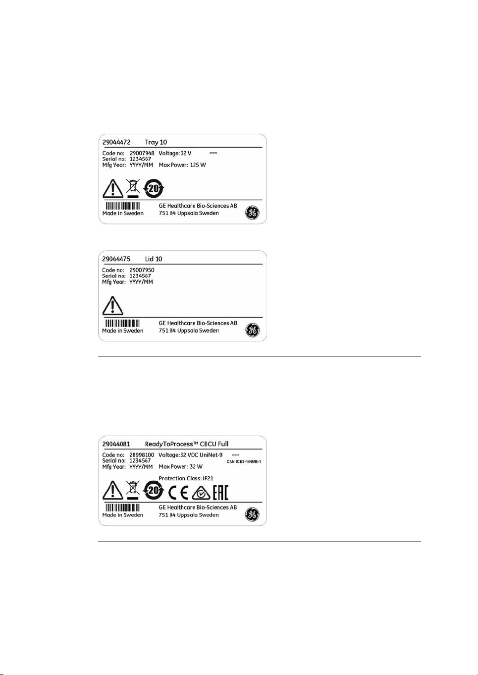
Tray and lid labels
The following illustrations show examples of the labels attached to the trays and lids.
Tray label
Lid label
ReadyToProcess CBCU label
The instrument label on the CBCU is located on the underside of theunit. The illustration
below isan example of the label attached to aCBCU with full configuration. Corresponding
labels are attached to the CBCU units with alternative configurations.
28 ReadyToProcess WAVE 25 Operating Instructions 29009597 AD
Page 29

ReadyToProcess Pump 25 label
The following illustraton shows an example of the label located on the rear panel of the
pump.
Symbol description
The following symbols are used in the labels.
2 Safety instructions
2.2 Labels
2.2.1 Instrument labels
DescriptionLabel
Warning! Read the user documentation before using the sys-
tem. Donot open anycovers or replace partsunless specifically
stated in the user documentation.
This symbol indicates that electrical and electronic equipment
must notbe disposed of as unsorted municipal waste andmust
be collectedseparately. Please contact an authorizedrepresentative of the manufacturer for information concerning the decommissioning of equipment.
This symbol indicates that the product contains hazardous
materials in excess of the limits established by the Chinese
standard GB/T 26572 Requirements for Concentration Limits
for Certain Hazardous Substances in Electrical and Electronic
Products.
This symbolindicates thatthe systemcomplies withapplicable
European directives.
This symbolindicates thatthe systemcomplies withapplicable
requirements for Australia and New Zealand.
ReadyToProcess WAVE 25 Operating Instructions 29009597 AD 29
Page 30

2 Safety instructions
2.2 Labels
2.2.1 Instrument labels
Frequency
Max. Power
DescriptionLabel
Eurasian Conformitymark: the singleconformity markindicates
that the product is approved for circulation on the markets of
the member states of the Eurasian Customs Union.
This symbol indicates that ReadyToProcess WAVE 25 hasbeen
certified by a Nationally Recognized Testing Laboratory (NRTL).
This product Conforms to UL 61010-1, and is Certified to
CAN/CSA-C22.2 No. 61010-1.
Electrical requirements:Voltage
Voltage (VAC )
•
Voltage (VDC )
•
Frequency (Hz)
•
Max. power (VA)
•
Degree of protection provided by the enclosure.Protection Class
CAN ICES-1/NMB1
Year (YYYY) and month (MM) of manufactureMfg. Year
CAN ICES-1/NMB-1 indicates that this product complies with
the Canadianstandard ICES-001 concerning technical requirements relative to radiated noise emissions from Industrial, Scientific and Medical radio frequency generators.
30 ReadyToProcess WAVE 25 Operating Instructions 29009597 AD
Page 31

2.2.2 Safety labels
Safety labels on ReadyToProcess
WAVE 25 rocker
The following symbols can be found on the rocker.
DescriptionLabel
Warning! Read the user documentation before using the sys-
tem. Donot open anycovers or replace partsunless specifically
stated in the user documentation.
Indicates a risk for body parts getting caught between two
parts of the system andthat care must betaken to avoidinjury.
Safety labels on ReadyToProcess
Pump 25
The following symbols can be found on the pump.
2 Safety instructions
2.2 Labels
2.2.2 Safety labels
Safety labels on filter heater
The following symbols can be found on the filter heater.
DescriptionLabel
Warning! Indicates a risk for fingers getting caught between
moving partsin thepump andthat caremust be taken to avoid
injury.
DescriptionLabel
Warning! Indicates a hot surface and that care must be exer-
cised to prevent injury.
ReadyToProcess WAVE 25 Operating Instructions 29009597 AD 31
Page 32

2 Safety instructions
2.2 Labels
2.2.2 Safety labels
Safety labels on tray
The following symbols can be found on the tray.
DescriptionLabel
Warning! Indicates a hot surface and that care must be exer-
cised to prevent injury.
LEFT indicates the left side of the tray.
Warning! Indicates a hot surface and that care must be exer-
cised to prevent injury.
RIGHT indicates the right side of the tray.
32 ReadyToProcess WAVE 25 Operating Instructions 29009597 AD
Page 33

2.2.3 Additional labels
Illustration of Cellbag label
The following image is an example of the label attached to the cellbag.
2 Safety instructions
2.2 Labels
2.2.3 Additional labels
Illustration of DO sensor label
The following image is an example of the DO sensor label attached to the cellbag next
to the DO sensor.
ReadyToProcess WAVE 25 Operating Instructions 29009597 AD 33
Page 34

2 Safety instructions
2.2 Labels
2.2.3 Additional labels
Illustration of pH sensor label
The following image is an example of the pH sensor label attached to the cellbag next
to the pH sensor.
Illustrations of fiber cable labels
The following image shows the label to be attached to the optical fiber cable of the DO
sensor.
The following image shows the label to be attached to the optical fiber cable of the pH
sensor.
Illustration of pump head label
The following image shows the label attached to the pump head.The label indicates the
pumping direction of the pump.
34 ReadyToProcess WAVE 25 Operating Instructions 29009597 AD
Page 35

2.3 Emergency procedures
Introduction
This section describes how to perform an emergency shutdown of ReadyToProcess
WAVE 25. This section also describes the result in the event of power failure or network
interruption.
WARNING
Access to power switch and power cord with plug. Do not block
access to the power switch and power cord. The power switch
must always be easy to access. The power cord with plug must
always be easy to disconnect.
Emergency shutdown
In an emergency situation, stop the run in one of the following ways:
•
Stop the run from System Control by clicking the Stop icon, if UNICORN is in control
of the system.
Result: Thecurrent run isended and theinstrument will go to Ready state, indicating
that it is ready for a new run.
2 Safety instructions
2.3 Emergency procedures
.
or
•
Switch off power by pressing the Power button on the rocker front panel.
Result: The run is interrupted. The light in the Power button is turned off.
ReadyToProcess WAVE 25 Operating Instructions 29009597 AD 35
Page 36

2 Safety instructions
2.3 Emergency procedures
Normal and forced shutdown
If the Power button is pressed once, a normal shutdown is performed. If the button is
pressed and held, a forced shutdown is performed.
The following table describes normal shutdown and forced shutdown.
No light: power is OFF.Green light: power is ON.
DescriptionType of shutdown
Normal shutdown: pressthe Power
button once.
Forced shutdown: press and hold
the Power button.
All processes are stopped. The system waits
for acknowledgement from the processes before shutting down the instrument.
All processes are stopped. The instrument is
shut down immediately.
Power failure
The result of a power failure or emergencyshutdown depends on which unit is affected.
will result in...Power failure to...
ReadyToProcess WAVE 25
36 ReadyToProcess WAVE 25 Operating Instructions 29009597 AD
The run is interrupted immediately.
•
The data collected before the power failure is
•
stored in the instrument and can be saved when
power returns.
Page 37

2 Safety instructions
2.3 Emergency procedures
will result in...Power failure to...
Client computer
Restart after emergency
shutdown or power failure
If System Settings:Auto start:Rocker and System Settings:Auto start:CBCU are set to
Resume activity, the following will happen when the system is re-energized:
•
The rocker and the CBCU(s) will restart using the same values as before the power
inerruption.
•
UNICORN will ask if you want to save or discard the run data collected before the
power interruption.
Note:
Data collection, media control, and regulation of pHand DO must be reinitiated
manually by reconnecting to the system and starting a new run.
Uninterruptible power supply
(UPS)
A UPS can postpone power failure, which allows time for a controlled shut-down of the
bioreactor system and prevents data loss.
For UPS power requirements, see the system specifications in ReadyToProcess WAVE 25
System Handbook. Take the specifications for the client computer and monitor into account. Refer to the manufacturers' documentation.
The cellcultivation run continueswithout interruption.
The operatorwill not, however, beable to view system
status, change settings or send manual instructions
during power failure of client computer. The software
retains the run settings when the power is restored.
ReadyToProcess WAVE 25 Operating Instructions 29009597 AD 37
Page 38

2 Safety instructions
2.4 Recycling information
2.4 Recycling information
Introduction
This section contains information about the decommisioning of ReadyToProcess WAVE
25.
Decontamination
The product must be decontaminated before decommissioning. All local regulations
must be followed with regard to scrapping of the equipment.
Disposal of the product
When taking the product out of service, the different materials must be separated and
recycled according to national and local environmental regulations.
Recycling of hazardous
substances
The product containshazardous substances.Detailed information is available from your
GE representative.
Disposal of electrical
components
Waste electricaland electronicequipment must notbe disposed of as unsorted municipal
waste and must be collected separately. Please contact an authorized representative
of themanufacturer for information concerning the decommissioning of the equipment.
38 ReadyToProcess WAVE 25 Operating Instructions 29009597 AD
Page 39

2 Safety instructions
2.5 Declaration of Hazardous Substances (DoHS)
2.5 Declaration of Hazardous Substances (DoHS)
根据SJ/T11364-2014《电子电气产品有害物质限制使用标识要求》特提供如下有关污染控制方面的
信息。
The following product pollution control information is provided according to SJ/T11364-2014 Marking
for Restriction of Hazardous Substances caused by electrical and electronic products.
电子信息产品污染控制标志说明
Explanation of Pollution Control Label
该标志表明本产品含有超过中国标准GB/T 26572 《电子电气产品中限用物质的限
量要求 》中限量的有害物质。标志中的数字为本产品的环保使用期,表明本产品
在正常使用的条件下,有毒有害物质不会发生外泄或突变,用户使用本产品不会
对环境造成严重污染或对其人身、财产造成严重损害的期限。单位为年。
为保证所申明的环保使用期限,应按产品手册中所规定的环境条件和方法进行正
常使用,并严格遵守产品维修手册中规定的定期维修和保养要求。
产品中的消耗件和某些零部件可能有其单独的环保使用期限标志,并且其环保使
用期限有可能比整个产品本身的环保使用期限短。应到期按产品维修程序更换那
些消耗件和零部件,以保证所申明的整个产品的环保使用期限。
本产品在使用寿命结束时不可作为普通生活垃圾处理,应被单独收集妥善处理。
This symbolindicates the product contains hazardous materials inexcess of the limits
established by the Chinese standard GB/T 26572 Requirements of concentration
limits for certain restricted substances in electrical and electronic products. The
number in the symbol is the Environment-friendly Use Period (EFUP), which indicates
the period during which the hazardous substances contained in electrical and electronic products will notleak or mutate under normal operating conditions so that the
use ofsuch electrical andelectronic productswill not result in any severe environmental pollution,any bodily injuryor damage toany assets. Theunit of theperiod is “Year”.
In order to maintain the declared EFUP, the product shall be operated normally according to the instructions and environmental conditions as defined in the product
manual, and periodic maintenance schedules specified in Product Maintenance Procedures shall be followed strictly.
Consumables or certain parts may have their own label with an EFUP value less than
the product. Periodic replacement of those consumables or parts to maintain the
declared EFUP shallbe done in accordance withthe ProductMaintenance Procedures.
This product must not be disposed of as unsorted municipal waste, and must be
collected separately and handled properly after decommissioning.
ReadyToProcess WAVE 25 Operating Instructions 29009597 AD 39
Page 40

2 Safety instructions
2.5 Declaration of Hazardous Substances (DoHS)
有害物质的名称及含量
Name and Concentration of Hazardous Substances
产品中有害物质的名称及含量
Table of Hazardous Substances’ Name and Concentration
部件名称
Component name
本表格依据SJ/T 11364的规定编制。
This table is prepared according to SJ/T 11364.
0:
X:
•
0:
表示该有害物质在该部件所有均质材料中的含量均在 GB/T 26572规定的限量要求以下。
表示该有害物质至少在该部件的某一均质材料中的含量超出 GB/T 26572规定的限量要
求。
此表所列数据为发布时所能获得的最佳信息.
Indicates that this hazardous substance contained in all of the homogeneous materials for
this part is below the limit requirement in GB/T 26572.
有害物质
Hazardous substance
铅
(Pb)
汞
(Hg)
镉
(Cd)
六价铬
(Cr(VI))
多溴联苯
(PBB)
多溴二苯醚
(PBDE)
OOOOOX28988000
OOOOOX29032003
OOOOOX29044213
OOOOOX29044216
OOOOOX29044081
X:
•
40 ReadyToProcess WAVE 25 Operating Instructions 29009597 AD
Indicates that this hazardous substance contained in at least one of the homogeneous
materials used for this part is above the limit requirement in GB/T 26572.
Data listed in the table represents best information available at the time of publication.
Page 41

3 System description
About this chapter
This chaptergives a brief overview ofReadyToProcess WAVE25. For more detailed information, refer to ReadyToProcess WAVE 25 System Handbook.
In this chapter
This chapter contains the following sections:
3 System description
See pageSection
423.1 System overview
443.2 ReadyToProcess WAVE 25 rocker
523.3 ReadyToProcess CBCU
553.4 ReadyToProcess Pump 25
583.5 Cellbag bioreactor
613.6 UNICORN software overview
ReadyToProcess WAVE 25 Operating Instructions 29009597 AD 41
Page 42

3 System description
3.1 System overview
3.1 System overview
Introduction
ReadyToProcess WAVE 25 is intended for cell cultivation.
A disposable Cellbag bioreactor is placed on a rocker and filled with gas, partially filled
with culture medium, and inoculated with cells. Gas transfer and mixing of culture is
accomplished by wave-induced agitation, performed by the rocker unit.
The cell culture volume range per Cellbag bioreactor is 0.3 to 25 L depending on bioreactor size, and working volume may be expanded up to 10 times during one cultivation.
The system, composed of the rocker, ReadyToProcess CBCU andReadyToProcess Pump
25, enables measurement and control of pH, DO, weight and media distribution, and
provides different gas flow and gas mixing possibilities.
•
In single mode, the system supports culture in one Cellbag bioreactor at one time.
The rocker is connected to one ReadyToProcess CBCU and up to three
ReadyToProcess Pump 25 units.
•
In dual mode, the system supports culture in two Cellbag bioreactors placed on the
same tray. Therocker is connected to up to two ReadyToProcess CBCU units and up
to threeReadyToProcess Pump 25units for independentcontrol ofculture conditions
in the two bioreactors.
The system is controlled from a PC running UNICORN software version 7 or later. The
system can also be controlled from a supervisory control and data acquisition (SCADA)
system, such as the Emerson DeltaV™ control system, using the integrated OPC server.
Contact GE for instructions and guidance for OPC.
42 ReadyToProcess WAVE 25 Operating Instructions 29009597 AD
Page 43

Illustration of the system
1 432
58 7 6
The illustration below shows the main system units for use in single mode with one
ReadyToProcessPump 25. Dual mode usestwo ReadyToProcessCBCU unitsfor controlling
the two Cellbag bioreactors independently. Both single and dual modes can support up
to three ReadyToProcess Pump 25 units.
3 System description
3.1 System overview
DescriptionPart
Hatch1
Filter heater2
Cellbag bioreactor3
ReadyToProcess Pump 254
ReadyToProcess WAVE 25 Operating Instructions 29009597 AD 43
ReadyToProcess CBCU5
ReadyToProcess WAVE 25 rocker6
Tray7
Lid8
Page 44

1
3
4
5
2
3 System description
3.2 ReadyToProcess WAVE 25 rocker
3.2 ReadyToProcess WAVE 25 rocker
Introduction
The rocker is the main unit of the system. Through the rocker, weight is measured, and
temperature, rocking speed, rocking angle and rocking motion are controlled.
The rocker contains four load cells for monitoring the weight of the Cellbag bioreactor
and content. The placement of the load cells allows independent weight measurement
of the two Cellbag bioreactors in dual mode.
The rocker also contains an embedded microprocessor, which allows the system to be
controlled independently of the performance of the connected network and client
computer.
For specifications of the rocker, refer to the ReadyToProcess WAVE 25 System Handbook
or the data file for ReadyToProcess WAVE 25, available for download from
www.gelifesciences.com/wave.
Front view of the rocker
The illustration below shows the front view of the rocker.
44 ReadyToProcess WAVE 25 Operating Instructions 29009597 AD
Page 45

3 System description
3.2 ReadyToProcess WAVE 25 rocker
DescriptionPart
Rocker platform1
Temperature sensors2
Rocker base3
Power button4
Location of adjustable foot5
Power button
The Power button indicates the status of the rocker according to the list below.
DescriptionImageLight indicator
The power is OFF.No light
The rocker is starting up.Green flashing light
Green steady light
The poweris ON andthe rocker is operational.
Red flashing light
The rocker failed to connect to other
components in the system.
Indicates an error of the rocker.Red steady light
ReadyToProcess WAVE 25 Operating Instructions 29009597 AD 45
Page 46

1 2 4
3
5 6 7
3 System description
3.2 ReadyToProcess WAVE 25 rocker
Adjustable foot
The adjustable foot is placed in the front right corner of the rocker base when viewed
from the front. It is used to distribute weight evenly over the four rocker feet.
Use the supplied adjustable foot wrench to adjust the foot.
Rear view of the rocker
The illustration below shows the rear panel of the rocker.
DescriptionPart
15-pin D-sub connector, used for digital and analog I/O signals1
Filter heater connectors2
Tray connector3
UniNet-9 ports4
USB ports5
Ethernet connector6
7
46 ReadyToProcess WAVE 25 Operating Instructions 29009597 AD
Power connector
Note:
The rocker is fitted with internal electrical fuses that arenot user-replaceable.
Page 47

Tray and lid sizes
1
2
3
4
Trays and lids are available in the different sizes listed below:
Illustrations of tray and lid
The illustration below shows the rocker with Tray 50 attached.
3 System description
3.2 ReadyToProcess WAVE 25 rocker
LidsTrays
Lid 10Tray 10
Lid 20Tray 20
Lid 50Tray 50
DescriptionPart
Bag clamp (upper)1
Bag clamp opener (one in each upper corner)2
Bag clamp opener (one in each lower corner)3
Bag clamp (lower)4
The illustration below shows the rocker with Tray 50 and Lid 50 mounted.
ReadyToProcess WAVE 25 Operating Instructions 29009597 AD 47
Page 48

54
3
2
1
3 System description
3.2 ReadyToProcess WAVE 25 rocker
DescriptionPart
Rocker base1
Lid2
Tray3
Tubing exit4
Hatch5
48 ReadyToProcess WAVE 25 Operating Instructions 29009597 AD
Page 49

Prepare for tilt
When the system enters END mode, the tray prepares for tilt if System Settings:Rocker:Prepare for tilt at END is set to Yes. This moves the rocker to the mechanical end
position, which is 14 degrees from horizontal. This position can also be set by executing
the manual instruction Rocker:Prepare for tilt. See illustration below.
Tilt position
In order to facilitate tray change in system setup and sampling and harvest during and
after cell cultivation, it is possible to position the tray with the attached Cellbag bioreactor(s) into an upright position called tilt position. Follow the instructions below to put the
tray into tilt position.
The tray is shown without attached Cellbag bioreactor in the images below.
3 System description
3.2 ReadyToProcess WAVE 25 rocker
NOTICE
Take care when tiltingthe rocker tray with fullCellbag bioreactor(s)
attached.
ActionStep
1
ReadyToProcess WAVE 25 Operating Instructions 29009597 AD 49
Prepare for tilt as described above or select the largest possible angle in
UNICORN. Do not tilt the tray from an angle lower than 12°.
Page 50

1
2
3
3 System description
3.2 ReadyToProcess WAVE 25 rocker
ActionStep
2
Hold thetextured grip area on eachside of thetray and pullthe tray towards
you.
The illustration below shows the tilt position:
Filter heater
The filter heater prevents condensation and clogging of the outlet vent filter on the
Cellbag bioreactor.
50 ReadyToProcess WAVE 25 Operating Instructions 29009597 AD
Page 51

3 System description
3.2 ReadyToProcess WAVE 25 rocker
DescriptionPart
Filter heater1
Connector for connection to the rocker2
Filter heater stand3
ReadyToProcess WAVE 25 Operating Instructions 29009597 AD 51
Page 52

1
4
2
3
3 System description
3.3 ReadyToProcess CBCU
3.3 ReadyToProcess CBCU
Introduction
The control unit, ReadyToProcess CBCU, is connected to the rocker via a UniNet-9 connector. The full configuration mixes air/N2, O2, and CO2gas, and contains O2and CO
sensors, a mass flow controller, an optical pH sensor reader, and an optical DO sensor
reader. Three configurations are available:
•
ReadyToProcess CBCU pH: CO2, O2and pH.
•
ReadyToProcess CBCU DO: CO2, O2and DO.
•
ReadyToProcess CBCU Full: CO2, O2, pH and DO.
For specifications of the CBCU, refer to the ReadyToProcess WAVE 25 System Handbook
or the data file for ReadyToProcess WAVE 25, available for download from
www.gelifesciences.com/wave.
Front view of ReadyToProcess
CBCU
The illustrationbelow shows thefront panel of a fullyconfigured CBCU. The configuration
of your CBCU may vary from the configuration shown below.
2
52 ReadyToProcess WAVE 25 Operating Instructions 29009597 AD
Page 53

1
2
3
6
5
4
3 System description
3.3 ReadyToProcess CBCU
DescriptionComponentPart
Connector for pH sensor fiber cable.pH port1
Gas outlet for connection to Cellbag bioreactor.GAS MIX OUT2
Indicates the CBCU operating status.Status LED3
Connector for DO sensor fiber cable.DO port4
Status LED
The status LED indicates the CBCU operating status according to the following table.
DescriptionLight indicator
The CBCU is ready for operation.Steady green light
The CBCU is operating.Green flashing light
Indicates an internal error, but the CBCU is still operating.Red flashing light
Indicates an internal error, and the CBCU is not operating.Steady red light
Rear view of ReadyToProcess
CBCU
The illustration below shows the rear panel of a fully configured CBCU.
ReadyToProcess WAVE 25 Operating Instructions 29009597 AD 53
Page 54

3 System description
3.3 ReadyToProcess CBCU
DescriptionComponentPart
Power connection to the rocker.UniNet-9 port1
Indicates system connection status.CAN indicator LED2
CAN ID switch3
CAN ID
The CAN ID is a unit number used by UNICORN to recognize the CBCU that is connected
to the system.
The CAN ID is set by turning a switch on the CBCU rear panel (see illustration above). The
CAN ID should always be set to position 1 for use in single mode. For dual mode, set the
CAN ID to 1 for the CBCU connected to the left Cellbag bioreactor, and to 2 for the CBCU
connected to the right Cellbag bioreactor.
Tubing and connectors
Tubing andconnectors for gas flow aslisted below are deliveredwith the ReadyToProcess
CBCU. Tubing and connectors for liquid flow must be obtained separately.
Tubing
Switch for setting the CBCU unit number for system
recognition.
Inlet connection for O2supply.O2 IN4
Inlet connection for CO2supply.CO2 IN5
Inlet connection for air or N2supply.AIR/N26
LengthOuter diameterInner diameterItem
147.6" (375 cm)1/4" (6.4 mm)1/8" (3.2 mm)Tygon™ E3603
7.9" (20 cm)3/8" (9.5 mm)3/16" (4.8 mm)Silicone
Connectors
Inner diameterItem
1/8" to 3/16" (3.2 to 4.8 mm)Reducer connector, gas tubing
1/8" (3.2 mm)Connector, CBCU
54 ReadyToProcess WAVE 25 Operating Instructions 29009597 AD
Page 55

3.4 ReadyToProcess Pump 25
1
2
3
Introduction
The ReadyToProcess Pump 25 is a peristaltic pump unit that includes two roller pump
heads. The function of a given pump head is set in the UNICORN software. Up to three
pump units are supported in both single and dual mode.
For specifications of the pump, refer to the ReadyToProcess WAVE 25 System Handbook
or the data file for ReadyToProcess WAVE 25, available for download from
www.gelifesciences.com/wave.
Front view of the pump
The illustration below shows the front panel of the pump.
3 System description
3.4 ReadyToProcess Pump 25
DescriptionPart
Pump head flip top1
Pump head2
Status LEDs for pumping function per pump head3
ReadyToProcess WAVE 25 Operating Instructions 29009597 AD 55
Page 56

3
2
1
3 System description
3.4 ReadyToProcess Pump 25
Status LEDs
The status LEDs indicate the pumping function status according to the following table.
DescriptionLight indicator
The pumping function is ready for operation.Steady green light
Pumping is ongoing.Green flashing light
Indicates an internal error, but the pump is still operating.Red flashing light
Steady red light
Rear view of the pump
The illustration below shows the rear panel of the pump.
Indicates an internal error, and the pump is not operating
properly.
DescriptionComponentPart
Power connection to the rocker.UniNet-9 port1
Indicates system connection status.CAN indicator LED2
CAN ID switch3
56 ReadyToProcess WAVE 25 Operating Instructions 29009597 AD
Shows the unit number of the pump for recognition
by the system.
Page 57

CAN ID
3 System description
3.4 ReadyToProcess Pump 25
The CAN ID is a unit number used by UNICORN to recognize the particular pump unit
that is connected. If more than one pump unit is connected, the units are distinguished
by their CAN IDs.
The CAN ID is set by turning a switch on the pump rear panel (see illustration above).
The switch has four CAN ID positions, marked 1, 2, 3, and 4, respectively. The CAN ID
should be set to position 1 for the first pump, position 2 for the second pump and so on.
Tip:
The pumps are identified in UNICORN by their CAN ID. Label each pump unit
with its CAN ID to simplify identification of the physical pump.
ReadyToProcess WAVE 25 Operating Instructions 29009597 AD 57
Page 58

3 System description
3.5 Cellbag bioreactor
3.5 Cellbag bioreactor
Introduction
Cell cultivation is performed inside the Cellbag bioreactor. The Cellbag bioreactor is delivered gamma irradiated and ready for use. It is intended for single use only and should
be discarded after use.
Cellbag bioreactor options
The Cellbag bioreactors are available in different configurations, of varying sizes and
equipped with various ports. Cellbag bioreactors with internal cell retention filters are
available for perfusion culture. If required, it is possible to customize the Cellbag bioreactors. The following bag sizes are available for ReadyToProcess WAVE 25:
•
2 L
•
10 L
•
20 L (single mode only)
•
22 L
•
50 L (single mode only)
58 ReadyToProcess WAVE 25 Operating Instructions 29009597 AD
Page 59

Illustration of Cellbag bioreactor
1
678
5432
9
The illustration shows a general Cellbag bioreactor. The configuration of your Cellbag
bioreactor may vary from the configuration shown below.
3 System description
3.5 Cellbag bioreactor
DescriptionPart
pH bag sensor port, located on the underside of the bag1
Outlet vent filter with pressure control valve2
Inlet vent filter3
Addition port4
DO bag sensor port, located on the underside of the bag5
Cellbag rod6
Clave™ sampling port7
Note:
Addition port8
Addition/harvest port9
The inlet and outlet vent filters are distinguished by the pressure control valve
on the outlet filter.
ReadyToProcess WAVE 25 Operating Instructions 29009597 AD 59
Page 60

1
2
3 System description
3.5 Cellbag bioreactor
pH and DO sensors
The Cellbag bioreactor may be equipped with optical sensors for monitoring pH and
dissolved oxygen (DO). The sensors are light sensitive and should be protected from excessive light. The sensors are located in the center of a sensor port on the Cellbag
bioreactor and must be coupled to a sensor adapter, see table below.
DescriptionPart
Bag sensor
port
Sensor
adapter
The sensor port is located onthe underside ofthe Cellbag bioreactor.
The actual sensor (white/yellow for pH, pink/black for DO is located
in the center (1) of the sensor port, see image below.
The sensor adapter is attached to the sensor port by the four pins (2).
The sensor adapter is located at one end of an optical fiber cable.
The opticallens of thefiber cable islocated in thecenter of thesensor
adapter. The fiber cable is connected to a sensor reader in the CBCU.
The fiber cable is connected to the pH or DO port on the CBCU front
panel.
60 ReadyToProcess WAVE 25 Operating Instructions 29009597 AD
Page 61

3.6 UNICORN software overview
In this section
This section gives an overview of the general operation of the UNICORN software: a
complete package for control, supervision and evaluation of cell cultivation runs. It also
describes how to access the help utility that is included in UNICORN.
This section contains the following subsections:
3 System description
3.6 UNICORN software overview
See pageSection
623.6.1 General UNICORN operation
653.6.2 Administration
663.6.3 System control
723.6.4 Evaluation
Note:
Software illustrations in these instructions are examples, and may differ from
your software in some details.
ReadyToProcess WAVE 25 Operating Instructions 29009597 AD 61
Page 62

3 System description
3.6 UNICORN software overview
3.6.1 General UNICORN operation
3.6.1 General UNICORN operation
UNICORN modules overview
UNICORN consists of four modules: System Control, Evaluation, Administration and
Method Editor.
The main functions of the modules are described in the table below.
Main functionsModule
Start, view and control runs.System Control
Open results, evaluate runs and create reports.Evaluation
Administration
Enter a UNICORN module
To enter a module:
•
click the Taskbar button of the module of interest,
or
•
choose themodule of interest in the Tools menu in any of the othersoftware modules.
The illustration below shows the Tools menu of the Evaluation module.
Perform userand systemsetup, systemlog and database
administration.
Create and edit methods.Method Editor
62 ReadyToProcess WAVE 25 Operating Instructions 29009597 AD
Page 63

Access the help utility
A comprehensive help utility is included in the UNICORN software. The table below describes how to access the different parts of the help utility.
a UNICORN module
3 System description
3.6 UNICORN software overview
3.6.1 General UNICORN operation
then...If you want to...
select Help:Help for... in the UNICORN module of interestfind information about
find information about
the itemcurrently selected and in focus (e.g., a
pane, a dialog, or a
method phase)
navigate theonline help
search for a specific
term in the online help
access manuals in PDF
format
press theF1 key with theitem of interest selectedand
•
in focus
or
click the Help icon in the open dialog
•
select Help:Helpfor... in anyof the UNICORN modules
•
(see illustration above)
in the TOC (Table of contents) pane, expand the
•
headings ofinterest tonavigate the content structure
click the heading of interest to open a section
•
select Help:Helpfor... in anyof the UNICORN modules
•
(see illustration above)
in the Search pane, enter the term of interest in the
•
input field
click the Search button
•
select Help:Helpfor... in anyof the UNICORN modules
•
(see illustration above)
in the TOC pane, expand the heading UNICORN 7.0
•
online documentation portal and select Documentation overview
in the PDF manuals section, click one of the text links
•
ReadyToProcess WAVE 25 Operating Instructions 29009597 AD 63
Page 64

3 System description
3.6 UNICORN software overview
3.6.1 General UNICORN operation
an instruction
then...If you want to...
In the Method Editor module:find information about
open a method
•
select theinstruction of interest in theInstruction box
•
in the Text instruction pane
press the F1 key
•
In the System Control module:
select Manual:Execute Manual Instructions
•
expand aheading and select the instruction of interest
•
press the F1 key
•
or
click the Help icon in the dialog
64 ReadyToProcess WAVE 25 Operating Instructions 29009597 AD
Page 65

3.6.2 Administration
Introduction
The Administration module is used to manage all functions of the UNICORN software.
Refer to UNICORN Administration and Technical manual for more information.
Icons in the Administration
module
The table below shows the Administration module icons.
FunctionIcon
User Setup is used to manage user access to UNICORN.
Access Groups and Network Users is used to manage access groupsand
network users.
3 System description
3.6 UNICORN software overview
3.6.2 Administration
E-mail Setup is used to set up an e-mail account for automated system
messages.
UNICORN and System Log providesthe system administrator with records
of usage and activity.
System Properties isused to define thesystem and editsystem properties.
Database Management is used for maintenance of the database.
ReadyToProcess WAVE 25 Operating Instructions 29009597 AD 65
Page 66

3 System description
3.6 UNICORN software overview
3.6.3 System control
3.6.3 System control
Introduction
The System Control module is used to start, view, and control a manual or method run.
System Control panes
As illustrated below, two tabs are available in the System Control module by default.
The Process Picture tab allows manual interactions with the system and provides
feedback on run parameters. The Chart tab shows a graphical presentation of data
throughout therun. Process picture, charts, runlogs, and rundata can be displayedeither
as separate tabs or as docked panes in the same window.
Refer to Section 5.4 Perform cultivation, on page 144 for information on how to perform
a run.
Tip:
To get more information than isshown in the Process Picture, select View:Run
Data to open the Run Data pane which presents current data in numerical
values.
Items in the process picture reflect the components includedin the system(for example,
the illustration above shows a system in single mode equipped with three pumps).
66 ReadyToProcess WAVE 25 Operating Instructions 29009597 AD
Page 67

3 System description
3.6 UNICORN software overview
3.6.3 System control
In dual mode, the process picture shows two Cellbag bioreactors on the rocker picture,
with separatecontrol iconsfor the individually controlled parameters in each bioreactor.
Icons for the left-hand bioreactor are in the upper half of the process picture and icons
for the right-hand bioreactor in the lower half.
Identifying system components in the process picture
This section describes how to identify the units in the process picture with respect to the
Cellbag bioreactors in single and dual mode.
•
The left-and right-hand Cellbag bioreactorsin dual mode are controlledby the CBCU
units with CAN ID 1 and 2 respectively. They are shown on the left and right sides of
the tray in the process picture. To avoid confusion, place the physical CBCU units on
the left and right sides of the tray as viewed from the front of the rocker.
•
Connections betweenthe Cellbag bioreactor(s) and therespective monitorand active
control units are indicated by connection lines in the process picture.
•
Pump units are identified in the process picture as 1, 2 or 3 according to their CAN
ID setting, and the pump heads on each unit are designated A (left) and B (right).
In dual mode, pump rolesfor the leftand right Cellbagbioreactors are labelled L and
R respectively.
Examples:
Pump 25: 1B refers to the right-hand pump head on the pump unit with CAN ID 1.
ReadyToProcess WAVE 25 Operating Instructions 29009597 AD 67
Page 68

3 System description
3.6 UNICORN software overview
3.6.3 System control
Pump 25: 2A refers to the left-hand pump head on the pump unit with CAN ID 2.
Tip:
Label the CBCU and pump unitswith their CANID settings to simplify correlation
of the physical units with the process picture.
In dual mode, place the pumps connected to the left and right Cellbag bioreactors on the left and right sides of the rocker respectively.
Actions in the Process Picture
pane
It is possible to interact with the Process Picture pane in the following ways:
then...If you want to...
Activate or deactivate
pH and DO measurement and control
Activate or deactivate
other functions
Hold the cursor over the right-hand side of the button,
and turn Reading and/or Control on or off as required.
You can only switch the Control setting if Reading is on,
and you cannot turn Reading off if Control is on.
Click on the right-hand side of the button. The text on the
button shows the current value of the function.
68 ReadyToProcess WAVE 25 Operating Instructions 29009597 AD
Page 69

function
3 System description
3.6 UNICORN software overview
3.6.3 System control
then...If you want to...
Click on the left-hand side of the button.Open the settings for a
The example below shows the settings for dissolved oxygen, DO.
Adjust the settings
Enter appropriate values in the Settings dialog and click
OK or press enter.
ReadyToProcess WAVE 25 Operating Instructions 29009597 AD 69
Page 70

3 System description
3.6 UNICORN software overview
3.6.3 System control
System settings
Each installed instrument has a set of default parameter values, called system settings.
The System Settings dialogin System Control is used toview and edit thesystem setting
for the currently selected instrument before the run is started. Follow the instructions
below to change the System Settings.
ActionStep
In the System Control module, select System:Settings.1
Result: The System Settings dialog opens with the Instructions displayed.
An example is shown below.
2
3
4
Manual instructions
It ispossible to interactmanually with an ongoing run using Manual instructions. Follow
the instructions below to perform manual instructions.
Note:
Select the instruction to edit from the list. Click the + symbol to show the instructions foreach category. Theinstructions in each category differdepending on the instrument configuration.
Select settings and choose parameter values for the selected instruction.
Click OK. Settings will apply until they are changed.
To returnto the default values defined in the instrument configuration,click
Set Parameters To Strategy Default Values.
It is also possible to interact with the system manually directly from the Process
Picture.
70 ReadyToProcess WAVE 25 Operating Instructions 29009597 AD
Page 71

ActionStep
In the System Control module:1
select Manual:Execute Manual Instructions
•
or
use the shortcut Ctrl+M.
•
Result: The Manual instructions dialog opens.
In the Manual instructions dialog:2
3 System description
3.6 UNICORN software overview
3.6.3 System control
Run data
Click the+ symbol to showthe instructions forthe instruction group that
•
you want to modify.
Select the instruction that you want to modify.
•
Enter the new values for the instruction.
•
3
The Run Data pane shows the current values of some parameters, for example rocking
motion and accumulated time. To change the Run Data display, select View:Run Data,
right click in the Run Data pane and:
•
•
To execute several instructions at the same breakpoint, select and edit an
instruction and click Insert. Repeat for several instructions.
Note:
To update parameter fields during run, check the Auto update... box.
To perform the instructions, click Execute.4
select Run Data Groups:Detailed to show more details
or
select Customize to customize the appearance of the Run Data pane.
ReadyToProcess WAVE 25 Operating Instructions 29009597 AD 71
Page 72

3 System description
3.6 UNICORN software overview
3.6.4 Evaluation
3.6.4 Evaluation
The Evaluation module is used to evaluate the results from bioreactor runs. Evaluation
is described in detail in the ReadyToProcess WAVE 25 System Handbook and UNICORN
Online Help.
72 ReadyToProcess WAVE 25 Operating Instructions 29009597 AD
Page 73

4 Installation
About this chapter
This chapter provides required information to enable users and service personnel to:
•
unpack the bioreactor system delivered from the factory
•
install the system units
•
install UNICORN 7.0 software
•
edit system properties
Read the entire installation chapter before starting to install ReadyToProcess WAVE 25.
NOTICE
The rocker contains load cells forweight measurementsand should
be handled with extra care. Do not place the rocker on any parts
that maymove. Avoid exposing theload cells tolateral forces, such
as pushing the unit sideways on the bench, which may cause disturbances in the measurement or damage the load cells.
4 Installation
In this chapter
This chapter contains the following sections:
See pageSection
744.1 Site preparation
834.2 Hardware installation
904.3 Software installation
ReadyToProcess WAVE 25 Operating Instructions 29009597 AD 73
Page 74

4 Installation
4.1 Site preparation
4.1 Site preparation
About this section
This sectiondescribes the site planning andthe preparations necessary before installation
of ReadyToProcess WAVE 25. The purpose is to provide plannersand technical staffwith
the data needed to prepare the laboratory for the installation.
In this section
See pageSection
754.1.1 Delivery and storage
764.1.2 Site requirements
814.1.3 Client computer specifications
74 ReadyToProcess WAVE 25 Operating Instructions 29009597 AD
Page 75

4.1.1 Delivery and storage
When you receive the delivery
boxes
•
Record on the packing slip if there is any apparent damage on the delivery boxes.
Inform your GE representative of any such damage.
•
Move the delivery boxes to a protected location indoors.
Storage requirements
The deliveryboxes should be storedin a protected location indoors.The following storage
requirements must be fulfilled for the unopened boxes.
4 Installation
4.1 Site preparation
4.1.1 Delivery and storage
Allowed rangeParameter
-25°C to 50°CAmbient temperature, storage
5% to 95% (non-condensing)Humidity, storage
ReadyToProcess WAVE 25 Operating Instructions 29009597 AD 75
Page 76

4 Installation
4.1 Site preparation
4.1.2 Site requirements
4.1.2 Site requirements
Space requirements
Prepare a clean working area on a stable laboratory bench. The bench must fulfill the
following requirements:
•
Recommended minimum bench space: 80 x 180 cm.
•
The bench must be clean, level, flat and sufficiently stable to withstand vibration
from the rocking.
•
Do not place any other vibrating equipment on the same bench, since vibrations
might affect the weight reading.
•
The benchmust be ableto support thetotal weight of the system, including the filled
Cellbag bioreactor. See Equipment dimensions and weight, on page 78. If other optional instruments are installed, their weights must also be included.
•
Do not place soft material, paper sheets or similar under the system, as this may
block the ventilation inlet.
WARNING
Access to power cord. Do not block access to the power cord. The
power cord must always be easy to disconnect.
76 ReadyToProcess WAVE 25 Operating Instructions 29009597 AD
Page 77

Illustration of system setup,
single mode
The illustration below shows the recommended setup of the bioreactor system on the
laboratory bench for operation in single mode.
4 Installation
4.1 Site preparation
4.1.2 Site requirements
Illustration of system setup, dual
mode
In dual mode, place the ReadyToProcess CBCU and ReadyToProcess Pump 25 units on
either side of the rocker to correspond with the L and R designations in the software.
ReadyToProcess WAVE 25 Operating Instructions 29009597 AD 77
Page 78

4 Installation
4.1 Site preparation
4.1.2 Site requirements
Equipment dimensions and
weight
The table below lists the outer dimensions and weights of the bioreactor system units.
Weight (kg)Dimensions, W x D x H (mm)System unit
24.0404 x 560 x 205Rocker
4.8276 x 360 x 117CBCU
3.8275 x 280 x 115Pump
4.5475 x 430 x 60Tray 10
7.3740 x 480 x 70Tray 20
9.5800 x 610 x 70Tray 50
1.7475 x 430 x 230Lid 10
3.3740 x 480 x 245Lid 20
3.9800 x 610 x 260Lid 50
Environmental conditions
The following general requirements must be fulfilled:
•
The room must have forced ventilation, adapted for use of CO2, O2and N2.
•
The system units should not be exposed to sources of heat, such as direct sunlight
The installation site must comply with the following specifications.
Environmental requirements
RequirementParameter
Indoor use onlyAllowed location
15°C to 32°CAmbient temperature, operation
20% to 80%, noncondensingRelative humidity, operating
800 to 1060 mbarAtmospheric pressure
Up to 2000 mAltitude, operation
78 ReadyToProcess WAVE 25 Operating Instructions 29009597 AD
Page 79

ment
4 Installation
4.1 Site preparation
4.1.2 Site requirements
RequirementParameter
Pollution degree 2Pollutiondegree of the intended environ-
Note:
Note:
For satisfactory temperature control, the ambient temperature must be at
least 5°C lower than the desired culture growth temperature.
The load cells in therocker are sensitive to changesin temperature. The ambient
temperature should be maintained as constant as possible for reliable weight
measurements.
Electrical power requirements
The table below specifies the power requirements:
Mains connection
SpecificationParameter
100 to 120 V AC ±10%Supply voltage
200 to 240 V AC ±10%
50/60 HzFrequency
Overvoltage category IITransient overvoltages
1500 VAMax power
EU or US plug, outlet fused or protected
by equivalent circuit breaker.
UK mains cable available on request.
Length of mains cable
2 m. Extension cables may be used if required.
WARNING
Protective ground. The product must always be connected to a
grounded power outlet.
Noise level
•
The noise level of the operating bioreactor system is below 65 dBA.
•
Audio warning signals have a higher noise level than the operating system.
ReadyToProcess WAVE 25 Operating Instructions 29009597 AD 79
Page 80

4 Installation
4.1 Site preparation
4.1.2 Site requirements
Heat output
The heat output data is listed in the table below.
unit, CBCU and pump.
Gas supply
The table below lists the gas supply required for each installed CBCU.
Heat outputComponent
Maximum 1500 WBioreactor system, including the rocker
Pressure (bar)Gas
Flow (L/min)
Normal mode
2
2
2
Flow (L/min)
Fast fill mode
3.51.31.0 to 1.5Compressed air/N
0.50.21.0 to 1.5CO
1.70.71.0 to 1.5O
80 ReadyToProcess WAVE 25 Operating Instructions 29009597 AD
Page 81

4.1.3 Client computer specifications
Introduction
The table below lists client computer specifications for a UNICORN 7.0 system for use
with ReadyToProcess WAVE 25.
ReadyToProcess WAVE 25 is supplied with UNICORN 7.0, which requires Windows 7. If
you wish to use ReadyToProcess WAVE 25 with an earlier version of UNICORN, contact
GE for assistance.
General computer specifications
Installation is supported for Windows 7 Professional, 32-bit or 64-bit, with Service Pack
1 or Windows 10 Professional 64-bit.
For information about compatibility between UNICORN versions and the supported operating systems and database versions see the UNICORN compatibility matrix at
http://www.gelifesciences.com/UNICORNcompatibility.
4 Installation
4.1 Site preparation
4.1.3 Client computer specifications
space
Architecture
Database ServerUNICORN Client
installation
Intel Dual Core
(or faster)
Note: •
1
UNICORN must be closed when the color scheme is changed.
UNICORN is tested using the English (U.S.) Code 1033 operating system
language version. Using other language versions of the operating system
may cause errors.
•
A screen resolution of 1280x1024 or higher is recommended. Parts of the
UNICORN user interface may not be displayed properly using a lower resolution.
•
Changing the default font and changing the font size from 100% in Windows may cause problems in the UNICORN user interface.
•
The Windows basic color scheme is recommended1.
Intel DualCore (or
faster)
Intel Dual Core (or
faster)
E-License ServerWorkstation
500 MB12 GB6 GB6 GBMin. free disk
2 GB3 GB3 GB3 GBMin.available RAM
NTFSNTFSNTFSNTFSDisc format
Intel DualCore (or
faster)
ReadyToProcess WAVE 25 Operating Instructions 29009597 AD 81
Page 82

4 Installation
4.1 Site preparation
4.1.3 Client computer specifications
•
•
•
Using the Windows 7 Aero color scheme is not recommended.
Windows power save features should be turned off to avoid conflicts with
system operations.
UNICORN is not compatible with the Windows 7 feature High DPI Awareness, which allows the graphic user interface to be scaled. The interface
scale must remain at 100% to avoid issues with clipping and misaligning
of parts of the UNICORN user interface. Normally, the scale is set at 100%
by default.
82 ReadyToProcess WAVE 25 Operating Instructions 29009597 AD
Page 83

4.2 Hardware installation
About this section
This section describes the installation procedure for ReadyToProcess WAVE 25.
In this section
4 Installation
4.2 Hardware installation
See pageSection
844.2.1 Unpack the system units
864.2.2 Connect the system components
ReadyToProcess WAVE 25 Operating Instructions 29009597 AD 83
Page 84

4 Installation
4.2 Hardware installation
4.2.1 Unpack the system units
4.2.1 Unpack the system units
Unpacking instruction
Follow the instructions below to unpack each box and to lift the system units onto the
bench.
ActionStep
1
2
3
Note:
Place the box on a smooth and flat surface with the correct side facing upwards.
Open thepackaging with a knife andremove the pieces of foamfrom around
the system unit.
Lift the system unit by the handles on each long side and place it on the
bench.
Keep each unit in an upright position during unpacking. Protect units from
bumping into other objects.
NOTICE
The rocker has a scale function (load cells) and should therefore
be handled with extra care. The rocker shall not be placed on any
parts that may move. Avoidexposing the loadcells to lateral forces,
such aspushing it sideways onthe bench, which may causedisturbances in the measurement, or damage the load cells.
CAUTION
Heavy object. Because of the significantweight of ReadyToProcess
WAVE 25 rocker, assistance from another person is highly recommended when lifting or moving the equipment. Use the handles
on the sides of the rocker when possible, and do not lift
ReadyToProcess WAVE 25 rocker with tray attached.
84 ReadyToProcess WAVE 25 Operating Instructions 29009597 AD
Page 85

Install the client computer
equipment
Install the client computer equipment according to the manufacturer's instructions. The
computer is either supplied as part of thebioreactor system deliveryor obtained locally.
IP settings for standalone installation
For a standalone installation, the client computer's network card that is connected to
the rocker should have the static IP 192.168.1.3. Refer to UNICORN Administration and
Technical manual, Appendix D for instructions on how to change these settings.
4 Installation
4.2 Hardware installation
4.2.1 Unpack the system units
NOTICE
Any computerused with the equipment shallcomply with IEC 60950
and beinstalled and used accordingto the manufacturer's instructions.
ReadyToProcess WAVE 25 Operating Instructions 29009597 AD 85
Page 86

4 Installation
4.2 Hardware installation
4.2.2 Connect the system components
4.2.2 Connect the system components
Connect system units to the
rocker
ReadyToProcess Pump 25 and ReadyToProcess CBCU units are connected to the rocker
with UniNet cables. Power to the units is supplied from the rocker.
Follow the instructions below to connect the system units to the rocker.
NOTICE
If UniNet cables are disconnected during a run, the run will be interrupted and must be restarted. Make sure that cables are properly secured before starting a run and avoid moving system units
during a run.
See Rear view of the rocker, on page 46 for the location of connectors on the rear panel
of the rocker.
ActionStep
Connect the ReadyToProcess CBCU unit(s) to the rocker.1
Connect the supplied UniNet cable between the UniNet-9 port on the
1
CBCU rear panel (see Rear view of ReadyToProcess CBCU, on page 53)
and the first available UniNet-9 port on the rocker rear panel. Up to two
ReadyToProcess CBCU units are used for operation in dual mode.
For single mode, set the CAN ID switch on the CBCU to position 1. For
2
dual mode using two CBCU units, set the CAN ID switches on the two
CBCU units to positions 1 and 2 respectively.
Tip:
In dual mode, label theCBCU units withtheir respective CAN ID to simplify
identification in the UNICORN software.
86 ReadyToProcess WAVE 25 Operating Instructions 29009597 AD
Page 87

4 Installation
4.2 Hardware installation
4.2.2 Connect the system components
ActionStep
Connect the ReadyToProcess Pump 25 unit(s) to the rocker.2
Connect the supplied UniNet cable from the UniNet-9 port on the rear
1
panel of the each pump (see Rear view of the pump, on page 56) to the
next available UniNet-9 port on the rocker rear panel.
Set the pump CAN ID to position 1 for the first pump, position 2 for the
2
second pump, and position 3 for the third pump.
Tip:
Label the pump units with their respective CAN IDto simplifyidentification
in the UNICORN software.
Connect the filter heater(s) to the rocker.3
Connect the filter heater cable to the filter heater port on the rocker rear
panel. Twofilter heaters are usedin dual mode,one connected to eachfilter
heater port.
Note:
The filter heater connector snaps into place in the socket to prevent it from
being disconnected by a sudden pull. To release the connector, pull the connector sleeve away from the socket.
Jumpers
Insert jumpers into any unused UniNet-9 ports onthe rocker. Jumpers are provided with
the system.
Connect to networkor computer
The system can be connected to a stand-alone computer, or to a network using either
Ethernet or wireless connection. Follow the appropriate instruction in the table below.
InstructionConnection
Stand-alone computer
ReadyToProcess WAVE 25 Operating Instructions 29009597 AD 87
Connect anetwork cable between the Ethernetconnector
on the rear panel of the rocker and the Ethernet port on
the computer.
Page 88

4 Installation
4.2 Hardware installation
4.2.2 Connect the system components
InstructionConnection
Ethernet
Wireless
Additional I/O connections
The 15-pin D-sub connector on the rear panel of the rocker provides two analog inputs,
four digital inputs and four digital outputs for controlling and monitoring additional
equipment. See the ReadyToProcess WAVE 25 System Handbook for details.
Connect to mains power
ActionStep
1
Connect the supplied power cordbetween the powerinlet on the rear panel
of the rocker and a grounded power outlet.
Connect anetwork cable between the Ethernetconnector
on the rear panel of the rocker and the network. Connect
the computer to the network.
Contact your GE representative for support on how to
establish and configure the network connection.
Connect a WiFi USB adapter to the USB port on the rear
panel of the rocker.
Contact your GE representative for support on how to
establish and configure the network connections.
2
Follow themanufacturer's instruction to connect powerto computer, monitor
and local printer (if used).
Prepare gas tubing
Tubing for gas connections (Tygon E3603 and silicone, see Tubing and connectors, on
page 54) is supplied with the ReadyToProcess CBCU.
For gas distribution with full gas mixing functionality (N2/air, CO2and O2), four pieces of
gas tubingare needed for each ReadyToProcess CBCU.Three pieces are used toconnect
the gas sources to the inlets on the rear panel of the CBCU, and one piece is used to
connect the gas mix outlet on the front panel of the CBCU to the Cellbag bioreactor.
Follow the instructions below to prepare tubing for gas distribution.
88 ReadyToProcess WAVE 25 Operating Instructions 29009597 AD
Page 89

4 Installation
4.2 Hardware installation
4.2.2 Connect the system components
ActionStep
1
Cut the Tygon tubing into pieces of appropriate length, one piece for connecting gas distribution from the CBCU to the Cellbag bioreactor and as
many pieces as required for connecting the gas mix sources to the CBCU.
Insert a CPC™ tubing connector into one end of each piece.2
3
For the tubing used to connect the CBCU to the Cellbag bioreactor, connect
the end without the CPC connector to the silicone tubing using the supplied
reducer connector.
ReadyToProcess WAVE 25 Operating Instructions 29009597 AD 89
Page 90

4 Installation
4.3 Software installation
4.3 Software installation
About this section
This section describes how to perform a complete UNICORN 7.0 installation on a standalone workstation(Full installation).Instructions on how to configure an e-license, define
a system, and set up a system printer are also included.
Note:
Additional information about software installation and configuration is available in the
UNICORN Administration and Technical manual.
In this section
For other types of installations, contact your GE representative for support .
This includes network installations when you want to access the
ReadyToProcess WAVE 25 system from several client computers or control
more than one system from a single computer, or to run the system from a
third-party controller.
See pageSection
914.3.1 Install UNICORN software
944.3.2 Configure an e-license
1014.3.3 Define the system
90 ReadyToProcess WAVE 25 Operating Instructions 29009597 AD
Page 91

4.3.1 Install UNICORN software
Introduction
The full UNICORN installation includes all software component parts, including the
UNICORN database, necessary to operate UNICORN and a connected local system. The
UNICORN software installed on the client computer must correspond to the version
provided inthe ReadyToProcessWAVE 25 rocker. Contact your GE representative in case
of uncertainty.
The installation includes the components described in the table below.
CharacteristicsSoftware component
4 Installation
4.3 Software installation
4.3.1 Install UNICORN software
UNICORN software
Database server
License server
Note:
Installation procedure
ActionStep
Insert the installation disk into your DVD drive.1
2
3
If the installation program does not start automatically, open the DVD in
Windows Explorer and double-click on the file Setup.exe to launch the program.
Use the Next> button to step through the installation procedure.
Tip:
You can exit the installation at any stage by clicking the Cancel button.
However, if you do this the installation will be incomplete and the software
cannot be used. You may alsoclick the Back button in some installation steps,
to return to a previous step to change selections.
The UNICORNsoftware includesthe four modules; Administration, MethodEditor, System Control and Evaluation.
The server software necessary to operate the database
where all UNICORN data is stored. Microsoft SQL Server®
Express Edition is used for this.
The license server software is used to authorize that the
UNICORN software installation is properly licensed.
For general technical specifications for UNICORN 7.0 computers, refer to Section 4.1.3 Client computer specifications, on page 81.
4
ReadyToProcess WAVE 25 Operating Instructions 29009597 AD 91
Provide input or selectionsas requested.See thenotes below for more information.
Page 92

4 Installation
4.3 Software installation
4.3.1 Install UNICORN software
NotesStep
Read and accept the license agreement.Licenseagreement
Type ofinstallation
Type of system
Destination folder
You should normally choose to perform a Full installation.
Perform a Custom installation only if advised todo so by a GE
representative.
Select Cell cultivation as the type of system. If you install
UNICORN for Chromatography, you will not be able to use the
software with ReadyToProcess WAVE 25.
Choose to install the software to the selected folder or change
the destinationfolder if desired. There must be sufficientspace
available in the destination folder.
Note:
The general UNICORN installation folder structure will be saved
in the folder selected in this step. However, the SQL Server software and e-license server software will be installed on the C
drive by default. If the available space for this is insufficient, the
installation may fail. The required space will vary depending on
what is previously installed on the computer but at least 2 GB
should be available to ensure that the installation will be completed correctly.
Select data storage locations for backup and archive storage.Data storage
The backup folder is used for back-up copies of the database,
automatically takenevery night. Backup material can berecovered to any UNICORN cell cultivation database.
The archive folder is used to move old data and recover space
in the database.Archived material can only be retrieved to the
original database.
By default UNICORN will suggest a Backup folder in the same
folder as the installation. However, if possible backups should
be saved on different physical drive than the active database
to reduce the risk of data loss in the event of a disk crash. This
drive must be installed on the same computer as where the
database is installed. Network folders cannot be used for this
purpose.
For additionalsecurity, it is recommended that the backupand
the archive folders are copied or moved at regular intervals to
another computer or storage media.
The backup and archive folders can be changed after installation using the UNICORN Configuration Manager.
92 ReadyToProcess WAVE 25 Operating Instructions 29009597 AD
Page 93

4 Installation
4.3 Software installation
4.3.1 Install UNICORN software
NotesStep
Password settings
Choose whether access to the UNICORN software should be
password-protected.
The password setting can be changed after installation using
the UNICORN Configuration Manager.
When the installation is complete, you may click Show Report to view an installation
summary report.
Before the system can be used, you will need to configure an e-license and define a
system. These functions are accessed from the Configure eLicense and Define System
buttons inthe Installationcompleted dialog, and are described in the following sections
in this chapter.
ReadyToProcess WAVE 25 Operating Instructions 29009597 AD 93
Page 94

4 Installation
4.3 Software installation
4.3.2 Configure an e-license
4.3.2 Configure an e-license
Introduction
An e-license is a licensing file retrieved from the GE e-licensing web site and stored on
the local computer. This section describes how to retrieve and configure an e-license.
To configure an e-license directly after installing the software, click Configure eLicense
in the final dialog ofthe installation procedure. Youcan also accessthe e-license configuration ata latertime usingthe UNICORN Configuration Tools installed under Windows
programs.
Types of e-license
The table below lists the different types of e-licenses available for UNICORN 7.0.
DescriptionType
Workstation license
Remote license
Dry license
Before you start
Access Code
Before you canretrieve an e-license from the GEsoftware e-licensingweb site, you must
have received an Access Code with your software or via courier mail. Without this code
you will not be able to configure the e-license. Contact your GE representative if you
have not received the code.
Internet connection
To activate the e-license, you must have access to the Internet. If you are configuring
the e-license for a stand-alone workstation with no external network access, retrieve
the e-license file using another computer and then move the file to the workstation
computer using, for example, a USB memory stick.
A workstation license is a node locked license that is used for
one client computer only.
A remote license is a floating license that can be used on any
workstation in a network.
A dry license is a floating license that can be used on any
computer in a network for all functionality except connecting
to an instrument.
94 ReadyToProcess WAVE 25 Operating Instructions 29009597 AD
Page 95

4 Installation
4.3 Software installation
4.3.2 Configure an e-license
Computer Ethernet address
You will need the physical address for the network card used for communication with
the instrument to complete the e-license configuration. Normally, this address is shown
in the Configure e-License dialog. If for some reason the address is not shown in the
dialog, follow the steps below to find the address.
Note:
If the computer is equipped with two interface cards you should verify that
the correct address is used.
ActionStep
1
Open a Command Prompt window
•
1
and
enter the command ipconfig/all.
•
2
Locate thelisting for theNetwork Interface Card (also calledEthernet adapter)
used to connect to the instrument.
3
Make a note of the Physical Address.
Note:
The physical address is a 6-digit hexadecimal number, with the digits separated by hyphens (e.g., F0-1F-AF-3E-42-1A). You can omit the hyphens if
you wish.
Tip:
If you type the address into a text editor or similar program you can copy it
the the Windows clipboard (you cannot copy text fromthe Command Prompt
window).
1
In Windows XP, click the Start button and choose Programs:Accessories:Command Prompt.
In Windows7, click the Windows iconand chooseAll Programs:Accessories:Command Prompt.
You can also press and hold the Windows key and then press the letter R. Type 'cmd' in the
input field and click OK or press Enter.
ReadyToProcess WAVE 25 Operating Instructions 29009597 AD 95
Page 96

4 Installation
4.3 Software installation
4.3.2 Configure an e-license
Initiate e-license configuration
Follow the steps below to initiate the e-license configuration.
ActionStep
In the Configure e-License dialog:1
Click Copy to Clipboard to copy the displayed Ethernet address to the
Windows clipboard.
Note:
If the address is not displayed, or if there are multiple network cards in the
computer, follow the steps described in Computer Ethernet address, on
page 95 to find the correct address. Do not click Copy to Clipboard.
Note:
When activating additional licenses, always use the Ethernet address for
the network card on the computer where the license server software is installed. Do not use the Ethernet addresses on additional client computers.
96 ReadyToProcess WAVE 25 Operating Instructions 29009597 AD
Page 97

4 Installation
4.3 Software installation
4.3.2 Configure an e-license
ActionStep
Click the hyperlink in the dialog to access the e-licensing web site.2
Result: The GE Healthcare software elicensing web site opens in your web
browser.
Enter your access code (see Access Code, on page 94) and click Login.3
Result: The Operations Portal opens.
ReadyToProcess WAVE 25 Operating Instructions 29009597 AD 97
Page 98

4 Installation
4.3 Software installation
4.3.2 Configure an e-license
Retrieve the e-license
Follow the steps below to retrieve the e-license.For help on how to retrieve an e-license,
go to Help & FAQ on the Operations Portal.
ActionStep
Click the link to Collect License.1
Result: The manage entitlements page opens listing the e-license(s) towhich
you are entitled.
Select the check-box for your UNICORN license and click Activate.2
Result: A manage entitlements data input page opens.
3
Enter the data requested. Items marked with a red dot are mandatory.
•
If, for some reason, the e-license cannot be saved to a file during the
•
configuration, select the option Ship to Email or Ship to Address. Normally, this will not be necessary.
Check whether you want to receive software updates and information
•
about related products.
Click the Next button to proceed to the next page.
•
Click Add New Host under the heading Nodelocked Hosts.4
Result: The create license host dialog opens.
98 ReadyToProcess WAVE 25 Operating Instructions 29009597 AD
Page 99

4 Installation
4.3 Software installation
4.3.2 Configure an e-license
ActionStep
5
Paste or type the computer Ethernet address into the Nodelocked Hosts
field. The address is either copied to the clipboard as described in Initiate e-
license configuration, on page 96 or obtained as described in Computer
Ethernet address, on page 95.
Click the OK button to proceed.
6
Check that the information displayed in the manage entitlements page is
correct, then click Generate.
Result: The License summary page opens.
7
On the License summary page, select the check-box for your license and
click Save to File.
Save the license file in a safe location.
Click Complete and Logout to close the software e-licensing web site.8
ReadyToProcess WAVE 25 Operating Instructions 29009597 AD 99
Page 100

4 Installation
4.3 Software installation
4.3.2 Configure an e-license
Connect the e-license to the
software
Follow the steps below to connect the e-license to the software.
ActionStep
In the Configure e-License dialog:1
Click Browseand navigate tothe location ofyour saved e-license, thenclick
Open to transferthe searchpath to the file into thee-License Configuration
dialog.
Click the Configure e-License button.2
Result: A confirmation dialog opens, showing that the configuration has
been successful.
Click OKin the confirmationdialog, then close the Configuree-License dialog.3
100 ReadyToProcess WAVE 25 Operating Instructions 29009597 AD
 Loading...