

GE Lumination RC Series, RC6, Lumination RX Series, Lumination LRC Series, LRC6 Installation Manual
...Page 1

Installation Guide
LuminationTM LED Luminaire
RC/LRC/RX/LRX Series - New Construction Frame
BEFORE YOU BEGIN
Read these instructions completely and carefully.
WARNING/AVERTISSEMENT
RISK OF ELECTRIC SHOCK
• Turn power off before inspection, installation or removal.
• Properly ground electrical enclosure.
RISK OF FIRE
• Follow all NEC and local codes.
• Use only UL approved wire for input/output connections.
Minimum size 18 AWG or 14 AWG for continuous runs.
RISQUES DE DÉCHARGES ÉLECTRIQUES
• Coupez l’alimentation avant d’’inspecter, installer ou déplacer le luminaire.
• Assurez-vous de correctement mettre à la terre le boîtier d’alimentation électrique.
RISQUES D’INCENDIE
• Respectez tous les codes NEC et codes locaux.
• N’utilisez que des ls approuvés par UL pour les entrées/sorties de
connexion. Taille minimum 18 AWG ou 14 AWG pour les rangées continues.
NOTICE
Lamp Housings RC6, RC8 or LRC6, LRC8 or RX6, RX8 or LRXR4, LRXR6, LRXR8 may be assembled with part FRAMExR. When Lamp Housings RC6,
RC8 or LRC6, LRC8 or RX6, RX8 or LRXR4, LRXR6, LRXR8 is assembled with Part FRAMExR the nal assembly complies with UL 1598 category IFAO
recessed luminaire requirements. LRX products are suitable for wet location covered ceiling only.
Les boîtiers de lampes RC6, RC8 ou LRC6, LRC8 ou RX6, RX8 ou LRXR4, LRXR6, LRXR8 peuvent être montés avec la pièce FRAMExR. Lorsque les
boîtiers des lampes RC6, RC8 ou LRC6, LRC8 ou RX6, RX8 ou LRXR4, LRXR6, LRXR8 sont montés avec la pièce FRAMExR, le montage nal respecte
les exigences des luminaires encastrés de la catégorie IFAO de la norme UL 1598. LRX produits conviennent pour emplacement humide couverte
au plafond uniquement.
Save These Instructions
Use only in the manner intended by the manufacturer. If you have any questions, contact the manufacturer.
Prepare Electrical Wiring
Electrical Requirements
The LED luminaire must be connected to the mains
supply according to its ratings on the product label.
Grounding Instructions
The grounding and bonding of the overall system
shall be done in accordance to local electric code of
the country where the luminaire is installed.
1
Page 2
1
2 3 4
5
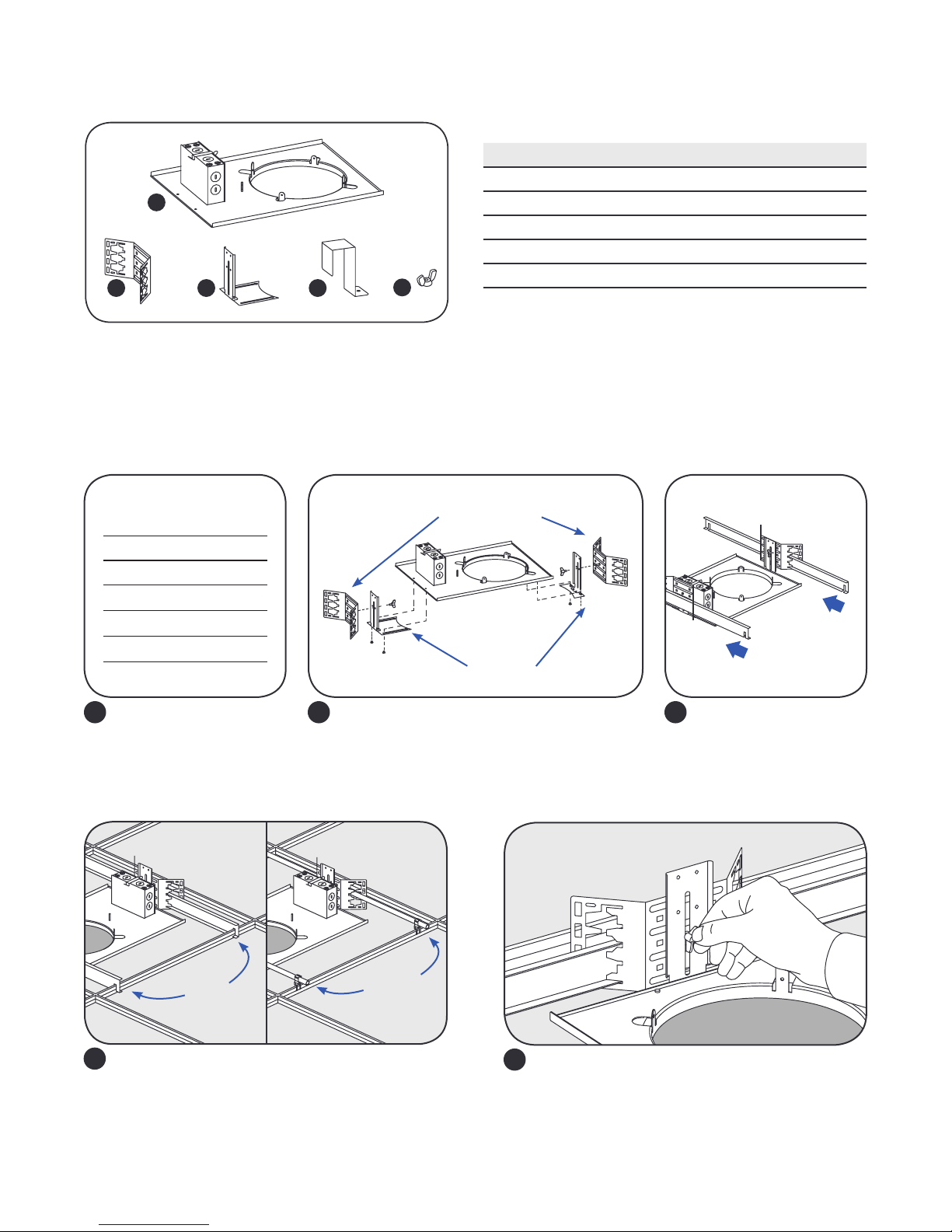
Components
Frame Installation
Provided Item Qty.
1 Frame (4-inch, 6-inch or 8-inch) 1
2 Mounting brackets 2
3 L-Bracket 2
4 U-Bracket (used only with RC/LRC Series Installs) 1
5 Wing nut 3
NOTE: Part 4 and 5 are only for RC/LRC product.
Fixture
Diameter
LRXR4 4.9–5.2 in.
RC6/LRC6 6.4–7.2 in.
RX6/LRXR6 5.91–6.60 in.
RC8/LRC8 7.5–8.9 in.
RX8/LRXR8 7.68–8.27 in.
Cut the appropriate size
1 2
hole into ceiling tile.
Hole
Diameter
Mounting brackets
L-brackets
Place side L-brackets on existing frame screws
and tighten with screwdriver on both sides of
the frame. Then attach mounting brackets to
both L-brackets with wing nuts (provided).
Adjust height and
tighten wing nut
Slide hanger bars through
3
adjustable mounting
brackets.
Bars
A B
Option A: Mount xture by attaching hanger bars
4
to T-Grid ceiling (BH3 SKU 94890).
Option B: Mount xture with ½” EMT conduit.
Note: Supplied by 3rd party.
Conduit
Adjust xture height to be ush with ceiling and
5
tighten both mounting bracket wing nuts.
2
Page 3

RC/LRC-Series Mounting
(RX-Series Mounting skip to step 15. LRXR-Series Mounting skip to step 18)
Through Wiring for RC-series 15A Circuit
Lumen Level
Maximum Number of Fixtures
(120V Input / 277V Input)
Minimum Spacing Requirements
for all Fixture Congurations
1000 84 / 195
1500 77 / 179
2000 59 / 138
3000 38 / 89
Center to center of adjacent luminaires 24”
Top of Luminaire to overhead building member 3”
Luminaire center to side building member 12”
4000 24 / 57
(For any other information refer to RC-series or LRC-series Installation Guides)
Remove cover
AC conduit
Screwdriver tip
Remove
AC wires
Open RC or LRC PSU box cover, disconnect AC conduit. Remove AC conduit wire from PSU box knockout hole using
6
at head screw driver.
AC line (Line, Neutral and Ground)
Insert AC line wires into the PSU box through
7
the knockout hole and connect wires (see wiring
diagrams at right).
LRC Wiring Diagram
Black /Red (+) Lead
White (-) Lead
TPC
Blue (+) Lead
*NOTE:
Black Lead - 120V ONLY
Red Lead - 277V ONLY
RC Wiring Diagram
Black (+) Lead
White (-) Lead
TPC
*Blue/Red (+) Lead
*NOTE:
Blue Lead - 120V ONLY
Red Lead - 277V ONLY
L N G
(0-10V) Purple (+) Dimming Lead
(0-10V) Grey (-) Dimming Lead
L N G
(0-10V) Purple (+) Dimming Lead
(0-10V) Grey (-) Dimming Lead
PSU Enclosure
White (-) Lead
Black (+) Lead
PSU Enclosure
Black (+) Lead
DRIVER
DRIVER
3
Page 4

Loop around
L-bracket
Wing nut
Place PSU box onto frame next to unused junction
8 9
U-bracket
box and secure with U-bracket by tightening wing nut.
Safety
tether
Feed button stop
and toggle through
hole in bracket
Toggle
Button stop
Attach the other end of the safety tether to the
1110
xture using one of the three holes located on the
xture brackets. Feed the button stop and toggle
through the hole and slide into the hole in the
bracket. Allow the xture to hang freely .
Take the provided safety tether and loop one end
of the tether around the L-bracket.
Connect two
quick connects
Assembled connector
housing
Plug together the light xture to the driver enclosure
with the supplied quick connects and assemble the
connector housing when nished.
Cut cable tie on light xture.
12
Position xture so
L-bracket does not
interfere with springs
Align the xture so that two of the three springs are
13
on each side of the L-bracket. This is necessary in
order to make sure that when the springs release,
the L-bracket does not interfere and prevent the
springs from making contact with the top of the
ceiling for proper support.
4
Page 5

installation
position for
14
Push xture through the hole in the ceiling. This will
engage the protruding arms, thus, releasing the
springs. The springs will draw the xture up into the
ceiling and hold it their tightly.
RX-Series Mounting
Final
springs
CAUTION
RISK OF PERSONAL INJURY - Operators shall ensure no
appendages are in the path of the torsion springs
as they are a pinch hazard when released. The
springs will release when the arm is exed downward.
Be cautious that no body part is in the path of the
spring when released.
RISQUE DE BLESSURE CORPORELLE - Les techniciens
veilleront à ce qu’aucun appendice ne se trouve sur
le chemin des ressorts de torsion, car ils présentent
un risque de pincement lorsqu’ils sont libérés. Les
ressorts seront libérés au moment de échir le bras vers
le bas. Faites attention à ce qu’aucune partie du corps
ne se trouve sur le chemin du ressort à sa libération.
Wiring Diagram
Line (black)
Neutral (white)
Ground (green)
AC line
Connect AC line to existing junction box. Connect conduit tting to the existing junction box. Connect the black,
15
Black
White
Green/Yellow
DRIVER
white and green/yellow wires of the input leads to the black, white and green AC line wires using UL Listed twist-on
wire connectors and close the junction box (see wiring diagram).
Springs up
Connect plugs
16
Connect the two quick connectors and reassemble
the connector box.
Reassembled
connector box
17
Load springs into upright position by twisting the
springs upward and carefully insert the xture to
the hole of the frame. Ensure xture is secure.
RISK OF PERSONAL INJURY - Operators shall ensure no appendages are in the path of the torsion springs as they are a pinch hazard when
released. The springs will release when the arm is exed downward. Be cautious that no body part is in the path of the spring when released.
RISQUE DE BLESSURE CORPORELLE - Les techniciens veilleront à ce qu’aucun appendice ne se trouve sur le chemin des ressorts de torsion, car
ils présentent un risque de pincement lorsqu’ils sont libérés. Les ressorts seront libérés au moment de échir le bras vers le bas. Faites attention à
ce qu’aucune partie du corps ne se trouve sur le chemin du ressort à sa libération.
CAUTION
5
Page 6

LRX-Series Mounting
Wiring Diagram
AC line
Connect conduit end with input leads to existing
18
junction box and make proper connections. Connect
the black, white, and green/yellow wires of the input
leads to the black, white and green wires using twiston wire connectors and close junction box.
Optional dimmer: When connecting with dimming
controller, wires must be run through another
separate knockout hole. Connect the violet (dimming
+) and gray (dimming -) wires to the violet and gray
wires of the xture.
NOTE: Please cover dimming leads with wire nuts if
you won’t connect with dimming leads.
Dimming compatibility for both 0-10V and phase cut,
please refer to GE website:
www.gelighting.com/dimming.
L
N
Dimming +
Dimming –
Ground
0-10 Volt Dimming
LED
Driver
Gray
Violet
Black
White
Violet
Gray
Green/Yellow
0-10V –
0-10V +
LRX
Fixture
To 0-10V
Dimmer
Lumens Setting Switch
NOTE: For 1000/650lm and 4000/3000lm, default output lumen is 1000lm and 4000lm respectively. Push switch up or
left to activate 650lm and 3000lm respectively.
6
Page 7

Springs up
Connect plugs:
3 pole to 3 pole
2 pole to 2 pole
19
Connect the two quick connectors and
reassemble the connector box.
Reassemble
connector box
20
Load springs into upright position by twisting the
springs upward and carefully insert the xture to
the hole of the frame. Verify reector trim is ush
with ceiling.
CAUTION
RISK OF PERSONAL INJURY - Operators shall ensure no
appendages are in the path of the torsion springs
as they are a pinch hazard when released. The
springs will release when the arm is exed downward.
Be cautious that no body part is in the path of the
spring when released.
RISQUE DE BLESSURE CORPORELLE - Les techniciens
veilleront à ce qu’aucun appendice ne se trouve sur
le chemin des ressorts de torsion, car ils présentent
un risque de pincement lorsqu’ils sont libérés. Les
ressorts seront libérés au moment de échir le bras vers
le bas. Faites attention à ce qu’aucune partie du corps
ne se trouve sur le chemin du ressort à sa libération.
This device complies with Part 15 of the FCC Rules. Operation is subject to the following two conditions: (1) This device may not cause harmful interference,
and (2) this device must accept any interference received, including interference that may cause undesired operation. CAN ICES-005 (A) / NMB-005 (A).
Note: This equipment has been tested and found to comply with the limits for a Class A digital device, pursuant to part 15 of the FCC Rules. These limits are
designed to provide reasonable protection against harmful interference when the equipment is operated in a commercial environment. This equipment
generates, uses, and can radiate radio frequency energy and, if not installed and used in accordance with the instruction manual, may cause harmful
interference to radio communications. Operation of this equipment in a residential area is likely to cause harmful interference in which case the user will be
required to correct the interference at his own expense.
All trademarks are the property of their respective owners. Information provided is subject to
change without notice. All values are design or typical values when measured under laboratory
conditions. Current, powered by GE is a business of the General Electric Company.
© 2018 GE.
www.currentbyge.com
IND259 (Rev 08/15/18) GE2029-8519
 Loading...