

GE RB790DT2BB Installation Insrtuctions

Installation Instructions
Free-Standing Electric Ranges
Questions? CaM1.800.GE.CARES(1.800.432.2737) or visit www.GEApp)iances.com
In Canada, call 1.800.561.3344 or visit www.GEApp)iances.ca
BEFORE YOU BEGIN
Readthese instructions completely and carefully,
" I MPO RTANT -- Savethese instructions
for local inspector's use.
" IMPORTANT -- Observe allgoverning
codes and ordinances.
. Note to Installer - Be sure to leave these
instructions with consumer.
, Note toconsumer - Keepthese instructions
for future reference.
. Skill level -Installation of this appliance
requires a qualified installer or electrician.
. Properinstallation is the responsibility of the
installer.
• Product failure dueto improper installation is
not covered under warranty.
FOR YOUR SAFETY:
! A w
Tip-Over Hazard
• Achild or adult can tip the range and bekilled.
Install the anti-tip bracket to the wall orfloor.
Engage the range to the anti-tip bracket bysliding the
range back such that the foot isengaged.
Re-engage the anti-tip bracket if the range is moved.
Failure to do socan result indeath or serious burns
to children or adults.
If youdid not receive ananti-tip bracket with your purchase,
call !.800.626.8774 to receiveone at no cost.fin Canada,
call !.800.561.3344.) Forinstallation instructions ofthe bracket,
visit: www.GEAppliances.com,fin Canada, www.GEAppliances.co.)
Anti-Tip Bracket
Kit Included
_,WARNING -- Beforebeginning
the installation,switchpower offat service
paneland lockthe servicedisconnecting
meansto preventpowerfrom being
switchedon accidentally.Whenthe service
disconnectingmeanscannot belocked,
securelyfastena prominentwarningdevice,
suchas atag,to the service panel.
MATERIALS YOU MAY NEED
SqueezeConnector (ULListed40 AMP)
(ForConduit 4-Wire Cord4' long OR
Installations Only} 3-Wire Cord 4'long
TOOLS YOU WILL NEED
Drill with 1/8" Bit Tin Snips
Safety Glasses Tape Measure
Adjustable Wrench Pliers
Level 1/4" Nut Driver
[i] REMOVE PACKAGI NG MATERIALS: Failureto remove packagingmaterials
couldresultindamage totheappliance.Remove allpackingpartsfromoven,racks,heating
elementsand drawer.Also,remove protectivefilmand labelson theouterdoor,cooktopand
control panel.
[TI PREPARE THE OPENING (FOR INDOOR USE ONLY)
Seeillustrations for all rough-in and spacing dimensions. Therange may be placed with 0"
clearance (flush) at the back wall and side walls of the cabinet.
+/-_/4"
_ 46"
* GEbranded models Installthe
have controlpanels outlet box
30 7/8"wide. on either
side ofthe CL
Electricity to the rangecan be disconnected at the outlet
without moving the range if the outlet is inthe preferred
location (remove lower drawer).
NOTE:Use a 4' power cord to prevent interference
with the storage drawer. Power cords 4½ to 6' long may
have to be dressed to allow for proper drawer closing.
MINIMUM DIMENSIONS BETWEEN COOKTOP,
WALLS ANDABOVE THE COOKTOP:
A. Make surethe wall covering, countertop, flooring
and cabinets around the range can withstand
the heat (up to 200°F) generated by the range.
B.Allow 30" minimum clearance between surface units and
bottom of unprotected wood or metal cabinet,
or allow a 24" minimum when bottom of wood or metal
cabinet isprotected by no lessthan 1/4" thick flame
retardant millboard covered with not less than No. 28
MSGsheet metal, (.015'1, .015" thick stainless steel, .024"
aluminum or .020" copper.
NOTEC
A _
B
C
Both
Sides
J
C.This appliance has been approved for 0" minimum spacing to adjacent surfaces above
the cooktop. However, a 6" minimum spacing to surfaces less than 15" above the cooktop
and adjacent cabinets is recommended to reduce exposure to steam, grease splatter and heat.
To reduce the risk of bums or fire when reaching over hot surface elements, cabinet storage
space above the cooktop should be avoided. If cabinet storage space is to be provided above
the cooktop, the risk can be reduced by installing a range hood that projects at least 5" beyond
the front of the cabinets. Cabinets installed above the cooktop must be nodeeper than 13".
[TI ELECTRICAL REQUIREMENTS
A WARNING: Thisappliance must be properly grounded.
WARN I NG: All new constructions, mobile homes,recreational vehicles and installations where
local codesdo not allow grounding through neutral, require o 4-conductor UL-listed range cord.
A WARN I NG: To prevent fire or shock, do not use an extension cord with this appliance.
A WARN ING: To prevent shock, remove house fuse or open circuit breaker before beginning
installation.
We recommend you have the electrical wiring and hookup of your range connected by aqualified
electrician. After installation, have the electrician show you how to disconnect power from the range.
You must use asingle-phase, 120/208 VAC or 120/240 VAC,60 hertz electrical system. If you connect
to aluminum wiring, properly installed connectors approved for use with aluminum wiring must be
used.
Effective January 1, 1996,the National Electrical Code requires that new construction (not existing)
utilize a 4-conductor connection to an electric range. When installing an electric range
in new construction, mobile home, recreational vehicle, or an area where local codes prohibit
grounding through the neutral conductor, refer to the section on four-conductor branch circuit
connections.
Check with your local utilities for electrical codes which apply in your area. Failure to wire your oven
according to governing codes could result in a hazardous condition. If there are no local codes, your
oven must be wired and fused to meet the National Electrical Code, NFPA No.
70 - latest edition, available from the National Fire Protection Association.
This appliance must besupplied with the proper voltage and frequency, and connected to an
individual, properly grounded, 40 amp (minimum) branch circuit protected by a circuit breaker or time-
delay fuse.
Use only a3-conductor or a 4-conductor UL-listed range cord. These cords may be provided with ring
terminals on wire and a strain relief device.
A range cord rated at 40 amps with 125/250 minimum volt range isrequired. A50 amp range cord
is not recommended but if used, itshould be marked for use with nominal 1%< diameter connection
openings. Care should be taken to center the cable and strain relief within the knockout hole to keep
the edge from damaging the cable.
. Because range terminals are not accessible after range is in position, flexible service conduit or cord
must be used.
The rating plate is located on the oven frame or on the side of the drawer frame.
Rating plate
[TI POWER CORD AND CONDUIT INSTALLATION
rA1 Remove wire cover (on the back ofrange) by removing screws using a 1/4" nut driver.
Do not discard these screws.
2 screws to remove
wire cover
Retaining
tab
Backof range
Forpower cordand 1"conduit only, remove the LCJ
r=-!
knockout ring (lSA") located on bracket directly
below the terminal block. To remove the
knockout, use apair of pliers to bend the
knockout ring away from the bracket and
twist until ring is removed.
Terminal
(appearance
may vary)
Knockout
ring in
bracket
For power cord installations only (seethe
next step ifusing conduit), assemblethe
strain relief inthe hole. insert the power
cord through the strain reliefand tighten.
Mow enough slack to easilyattach the
cord terminals to theterminal block. Iftabs
are present atthe end of thewinged strain
relief, theycan be removed for better fit.
NOTE:Do not install the power cord
without a strain relief. Thestrain relief
bracket MUST beinstalled before
reinstalling the rear range wiring cover.
Strain relief
rG1
Power cord
For 314"conduit installations only, purchase a squeezeconnector matching the diameter of your
conduit and assembleit inthe hole. Insertthe conduit through the squeeze connector andtighten.
Allowenough slackto easilyattach the wiresto the terminalblock.
NOTE:Do not installthe conduit without a squeezeconnector. The squeeze connector MUSTbe
installed before reinstalling the rear range wiring cover.
block
F_ 3-WIRE INSTALLATION
A WARN I NG: The neutralor ground wire of the powercord must be connected tothe neutral
terminal located inthe center of the terminal blockand the ground strap must connect theneutral
terminal to the ground plate.The power leadsmust be connected tothe lower left and the lowerright
terminals ofthe terminal block.
DO NOT remove the ground strap connection.
FORPOWER CORD INSTALLATION
A. Remove the 3 lower terminal screws from the terminal block.
B. Insert the 3terminal screws through each power cord terminal ring and into the lower
terminals of the terminal block. Be certain that the center wire (white/neutral)is connected to
the center lower position of the terminal block.
C.Tighten screws securely into the terminal block.
FOR CONDUIT INSTALLATION
A. Loosenthe 3 lowerterminal screws on the terminal block.Strip wire toexposed tip about 5/8" long.
B. Insertthe center (white/neutral) wire tipthrough thebottom center terminal block opening.On
certain models,the wire will needto be insertedthrough the ground strapopening and then into
the bottom center block opening. Insertthe two sidebare wire tips intothe lower left andthe lower
right terminal blockopenings.
C.Tighten the screws untilthe wire isfirmly secured (35to 50inch-lbs.).Do not over-tighten the
screws.
NOTE:ALUMINUM WIRING: Aluminum building wire may be used but it must be rated for the
correct amperage and voltage.
Power Cord
Terminal block
(appearance _----t_
may vary)
Neutral terminal
Ground stra
Ground
plate 4
Power cord --
PROCEEDTO STEP7.
Conduit
Terminal
Conduit _
I 31-I0831 I
01-12 GE
Printedin Mexico
[_] 4-WIRE INSTALLATION
A WAR N IN G:The neutralwire ofthe supplycircuit must beconnected tothe neutralterminal located in
the lowercenter ofthe terminal block.The powerleads mustbe connectedto thelower leftand the lower
rightterminals ofthe terminal block.Thegrounding leadmust beconnected tothe frame
of therange withthe ground plateand thegreen groundscrew.
FOR POWER CORD INSTALLATION
A. Removethe 3 lower terminal screws from the terminal block. Remove theground screw and ground
plate and retain them. Cutand discardthe ground strap. DONOTDISCARDANYSCRBA/S.
B. Insertthe oneground screwinto the power cordground wireterminal ring,through the ground plateand into
the frame ofthe range.
C. Insertthe3 terminalscrews(removed earlier)througheach powercord terminalring andinto thelower
terminalsof theterminal block.Becertain thatthe centerwire (white/neutral)isconnectedto thecenter lower
positionof theterminal block.Tightenscrewssecurelyinto theterminal block.
FOR CONDUIT INSTALLATION
A. Loosenthe 3lower terminal screwson theterminal block. Removethe ground screwand ground plate and
retainthem. Cut and discard theground strap. DONOT DISCARDANYSCREWS.Stripwire to exposed tip
about 5/8" long.
B. Insertthe ground barewiretip between therange frame andthe ground plate(removed earlier)and secure
t inplace with theground screw(removed earlier).Insertthe bare wire(white/neutral) tipthrough the bottom
centerof theterminal block opening.Insert thetwo sidebare wire tipsinto thelower leftand the lower right
terminal blockopenings.
C.Tighten the screwsuntil the wireis firmlysecured (35to 50inch-lbs.).Do not over-tighten the screws.
NOTE:ALUMINUM WIRING: Aluminum building wire may be used but it must be rated for
the correct amperage and voltage.
Before-Power Cord and Conduit
Ground _ _ "-,
strap Neutral terminal
After-Power Cord
/ ,
Terminal_ '
block l_ -_ o Bl
Gcr?Uwnd _
Neutral
_ terminal
__ Ground plate
_- (grounding to
range)
PROCEED TO STEP 7.
After-Conduit
Term na,--
(grounding
block
to range)
Wire
Ground screw "__
171 REPLACE THE WIRE COVER
Replacewire cover on range back
bysliding its left edgeunder the retaining
tabs and replacethe screws removed
earlier.Make surethat no wires are pinched
between cover and range back.
2 screws to remove
wire cover
Retaining
tab
Wire cover
Backof range
FB-I ANTI-TIP DEVICE INSTALLATION
Ti -Over Hazard
• A child or adult ca ntip the range and be killed.
• Install the anti-tip bracket to the wall or floor.
• Engage the range to the anti-tip bracket by sliding the
range back such that the foot isengaged.
• Re-engage the anti-tip bracket if the range is moved.
• Failure to do so can result in death or serious burns
to children or adults.
To reducethe risk oftipping the range, the
range must besecured by o properly installed
anti-tip bracket. See installation instructions
shipped with the bracketfor complete details
before attempting to install.
To checkif the bracket isinstalled and
engaged properly, look underneath the range
to seethat the rear leveling legis engaged
inthe bracket. On some models, thestorage
drawer or kick panelcan be removed for
easier inspection. Ifvisual inspection is not
possible,slide the range forward, confirm the anti-tip bracket issecurely attached to the floor or wall, and
slidethe range back so the leveling legis under the anti-tip bracket. Ifthe range is pulledfrom the wallfor
any reason, alwaysrepeat this procedure to verify the range isproperly secured by the anti-tip bracket.
Never completely remove the leveling legsor the range willnot be secured to the anti-tip bracket.
[_ LEVELTHE RANGE
A WARN ING: Nevercompletelyremove thelevelingleg
asthe range will not besecured to the anti-tip device properly.
MODELS WITH STORAGEDRAWER ORKICK PANELS
B]
F61
Plug in unit and slide into place. Pulldrawer out until it stops.
Lift front of drawer until the stops clear the guide. Remove the drawer.
Installthe oven shelves in the ovenand position therange where it willbe
installed.
Check forlevelness by placing a spirit level on oneof the oven shelves. Spirit level
Taketwo readings-with the level placed diagonally first
in onedirection and then the other.
rE1 The front leveling legs can beadjusted from the bottom and
the rear legs can beadjusted from the top orthe bottom.
Usean adjustable wrench to adjust the leveling legs until
the range is level.
[=_ LEVELTHE RANGE (CONT.)
r_ Position cord so that it does not interfere with drawer.
Place drawer rail on guides. Push the drawer in until it stops.
Lift front of drawer and push in until the stops clear
the guides.
D Lower thefront of the drawer and push in until it doses.
MODELS WITHBAKING OR WARMING DRAWERS
__ Lower
range
range
rA1 Plug in the unit.
Measure the height of your countertop at the rear of the opening (X).
rcl Adjust two rear leveling legs so that the rear of cooktop isat the same height
as the counter (Y).
r_ Slide unit into place.
r_ install ovenshelves in the oven and positionthe rangewhere it will beinstalled.
r_ Check for levelnessby placing a spirit level on oneof the oven shelves,
Take two readings-with the level placed diagonally first in onedirection
and then the other.
r_ Adjust front leveling legs until the range islevel.
FINAL INSTALLATION CHECKLIST
• Checkto make sure thecircuit breaker isclosed (RESET)or the circuit fuses arereplaced.
• Besure power is inservice to the building.
Check that all packingmaterials and tape havebeen removed. Thiswill include tape on metalpanel under
control knobs (ifapplicable), adhesive tape, wireties, cardboard and protective plastic. Failure to remove
these materials could result indamage to the appliance once the appliance hasbeen turned on and
surfaces have heated.
Check that thedoor and drawer are parallel to each otherand that both operate smoothly. If they donot,
seethe Owner's Manual forproper replacement.
Check to makesure that the rear levelingleg isfully inserted intothe Anti-Tip bracket and that the bracket
issecurely installed.
OPERATION CHECKLIST
• Turn onone ofthe surface units to observethat the element glowswithin 60seconds. Turnthe unit
off when glow isdetected. Ifthe glow is notdetected within the time limit, recheckthe range wiring
connections. Ifchange is required, retestagain. If nochange is required, havebuilding wiring checked for
proper connections andvoltage.
Check that theClock (on modelsso equipped) displayis energized. Ifo seriesof horizontal redlines appear
inthe display, disconnect power immediately. Recheckthe range wiring connections. If change is madeto
connections, retest again. Ifno change is required, havebuilding wiring checked for proper connections
and voltage. Itis recommended that the clock be changed ifthe red linesappear.
Note: Ifthe clock flashes "bAd"and then "LinE"with o loud tone, the neutralconnection to the range is
miswired. Checkthe terminal block connections and/or housewiring to correct.
Besure all range controlsare in the OFFposition before leaving therange.
lnstrucciones de instalaci6n
Cocinas elactricas independientes
_Preguntas? Llame a) !.800.GE.CARES(!.800.432.2737) o visite www.GEApp)iances.com
En Canada, Ilame al 1.800.561.3344 o visite www.GEAppliances.ca
ANTES DE COMENZAR
Lea estas instrucdones par completo y con
detenimiento.
" IMPORTANTE -- Guarde estas
instrucciones para el usa de inspectores
locales.
" IMPORTANTE -- Sigatodos
los c6digos y ordenanzas vigentes.
, Nota al instalador - Aseg0rese de dejar estas
instrucciones con el consumidor.
, Nota al consumidor - Conserve estas
instrucdones para referencia futura.
, Nivel de destreza - La instalaci6n de este
aparato debe efectuarla un instalador o
electricista caJificado.
. Elinstalador tiene la responsabilidad
de efectuar una instalad6n adecuada.
• Lagarant[a no cubre lasfolios del producto
debido a una instalaci6n incorrecta.
PARA SU SEGURIDAD
! A _ A
Riesqo deCaida
• Un nifio oadulto pueden volcar la cocina y morir.
• Instale el soporte anti-volcaduras sabre la pared o
el piso.
• Adhiera la estufa al soporte anti-volcaduras, volviendo
a deslizar la estufa de modo que elpie quede adherido.
• Vuelva a adherir el soporte anti-volcaduras si la estufa
semueve de lugar.
• Siesto no sehace, se podr6 producir lamuerte o
quemaduras graves en nifios oadultos.
Sino recibi6 un soporteanti volcaduras con sucompra,
Ilame al1.800.626.8774 para recibir uno sincosta.
(EnCanada, Ilame al!.800.56!.3344). Para recibir
instrucciones de instalaci6n delsoporte, visite:
GEAppliances.com(EnCanada, GEAppliances.ca.).
Kit desoporte
anti volcaduras incluido
,_ ADVERTENCtA -- Antes
de comenzar lainstalaci6n, apague el
encendido en elpanel de servicio ybloquee
el mediade desconexi6n del servicio afin de
evitar que elencendido se active deforma
accidental. Cuando elmedia de desconexi6n
del serviciono se pueda bloquear, ajuste
de manera segura unitem de advertencia
que est4 bienvisible, tal coma unaetiqueta,
sabre el panelde servicio.
MATERIALES QUE PUEDE NECESITAR
Conectorde presian
(S6topara instalaciones
conconductos
portacables)
(AprobadosparULde40 AMP)
Cablede 4abmbres de 4'
de largoO Cablede3 alambres
de4' de largo
HERRAHIENTAS NECESARIAS
Perforadora con hojalata
broca de 1/8" Cinta m4trica
Gafas de seguridad Alicates
Llave ajustable Llave de tuercas
Nivel de i/4"
TUeras para
| QUITE LOS MATERIALES DE ENV/O: Noquitarlosmateriales
de empaque puede provocardaflos al electrodom#stico. Quite todas las partes de empaque del
homo, bandejas, elementos calentadores y caj6n. Tambian, quite la pelfcula protectora y las
etiquetas de lapuerta exterior, estufa, y panel decontrol.
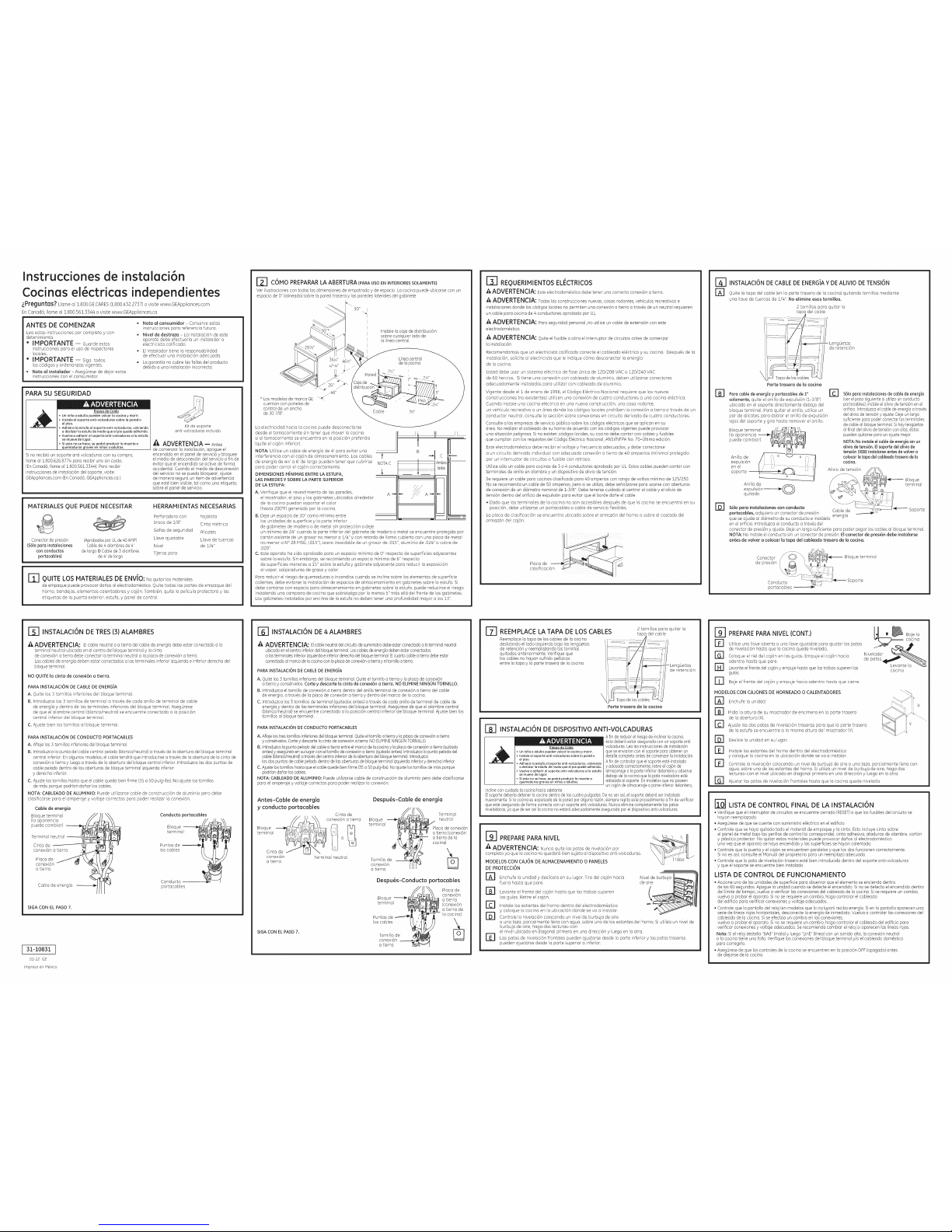
121 C6MO PREPARARLA ABERTURA(PARAUSO ENINTERIORESSOLAMENTE)
Ver ilustraciones contodas los dimensiones deempotrado y deespacio. Lacocina puede ubicarsecon un
espacio de 0"(alineado) sabrela pared trasera y losparedes laterales del gabinete.
I'" 30" j
i
i
Instale lacaja de distribuci6n
sabre cualquier ladode
la lineacentral.
.29_/8"
36_,J' 46Y_"
+/-Y4"
26"_
z \_,. 46"
* Losmodelos de marca GE "_
cuentan con paneles de
control de unancho
de 307/8".
La electricidad hacia la cocina puede desconectarse
desde el tomacorriente sin tener que mover la cocina
si eltomacorriente se encuentra en la posici6n preferida
(quite el caj6n inferior).
NOTA: Utilice un cable de energfa de 4'para evitar una
interferencia con el caj6n de almacenamiento. Los cables
de energia de 4_':'a 6'de largo pueden tenet que cubrirse
para poder cerrar el caj6n correctamente.
DIMENSIONESM/NIMAS ENTRELA ESTUFA,
LAS PAREDESYSOBRELA PARTESUPERIOR
DE LAESTUFA:
1
B --_ C
NOTAC Ambos
lados
A.Verifique que el revestimiento de las paredes, A -_ _- A "_
elmostrador, el piso y los gabinetes ubicados alrededor
de lacocina puedan soportar el calor
(hasta 200°F) generado par la codna.
B. Dejeun espacio de ]0" coma mfnimo entre --
los unidades desuperficie y laparte inferior -- _
de gabinetes de madera o de metal sinprotecci6n o deje
un minima de 24" cuando la porteinferior del gabinete de madera o metal se encuentre protegida par
cart6n aislante deun grosor no menor a Z/4" y con retardo de llama cubierto con una placa de metal
no menor a NO28 MSG,1.015"),acero inoxidable de ungrosor de .015",aluminio de .024" o cobre de
.020".
C. Esteaparato ha sido aprobado para un espado mfnimo de 0" respecto de superficies adyacentes
sabre la estufa. Sin embargo, serecomienda un espacio mfnimo de 6" respecto
de superficies menores a lS" sabre la estufa y gabinete adyacente para reducir la exposici6n
alvapor, salpicaduras degrasa y color.
Para reducir el fiesgo dequemaduras o incendios cuando se incline sabre loselementos de superficie
calientes, debe evitarse la instalaci6n de espacios de almacenamiento en gabinetes sabre laestufa. Si
debe contarse con espacio para almacenamiento en gabinetes sabre la estufa, puede reducirse el riesgo
instalando unacampana de cocina que sobresalga par Io menos S"mas all@del frente de los gabinetes.
Losgabinetes instalados par encima de la estufa no deben tenet una profundidad mayor a los Z]".
[]_] REQUERIMIENTOS ELECTRICOS
A ADVERTENCIA: Este electrodomastico debe tener una correcta conexi6n atierra.
A ADVERTENCJA: Todas los construcciones nuevas, casasrodantes, vehiculos recreativos e
instalaciones don@ los c6digos locales nopermiten una conexi6n a tierra atravas de unneutral requieren
un cable para cocinade 4 conductores aprobado par UL.
A ADVERTENCIA: Paraseguridad personal, no utilice un cablede extensi6n con este
electrodom4stico.
A ADVERTENCIA: Quiteel fusible oabra el interruptor de circuitos antes de comenzar
la instalaci6n.
Recomendamos que un electricista calificado conecte el cableado elactrico y sucocina. Despuas de la
instalaci6n, solicite al electricista que leindique c6mo desconectar la energia
de la cocina.
Usted debe usar un sistema e16ctrico de fase 0nica de 120/208 VAC o120/240 VAC
de 60 hercios. Si tiene una conexi6n con cableado de aluminio, deben utilizarse conectores
adecuadamente instalados para utilizar con cableado de aluminio.
Vigente desde el :i de enero de :1996,el C6digo Elactrico Nacional requiere que los nuevas
construcciones (no existentes) utilicen una conexi6n de cuatro conductores a una cocina elactrica.
Cuando instale una cocina elactrica en una nueva construcci6n, una casa rodante,
un vehiculo recreativo o undrea donde los c6digos locales prohiben la conexi6n a tierra a travas de un
conductor neutral, consulte la secci6n sabre conexiones en circuito derivado de cuatro conductores.
Consulte alos empresas de serviciop0blico sabre los c6digoselactricos que se aplican ensu
area. No realizarel cableado desu homo de acuerdo con losc6digos vigentes puede provocar
una situaci6n peligrosa. Sino existen c6digoslocales, su cocina debecontar con cables yfusibles
que cumplan con losrequisitos del C6digo El@ctricoNacional,ANSI/NFPANo. 70-01tima edici6n.
Esteelectrodom4stico debe recibir el voltaje y frecuenda adecuados, y debe conectarse
a un circuito derivado individual con adecuada conexi6n a tierra de 40 amperios (mfnimo) protegido
par un intemuptor de circuitos o fusible con retraso.
Utilice s6lo uncable para cocinas de3 o 4conductores aprobado par UL.Estos cablespueden contar con
terminales de anillo enalambre y un dispositivo dealivio de tensi6n.
Serequiere un cable para cocinasclasificado para 40 amperios conrango de voltios minima de125/250.
No serecomienda un cable deg0 amperios, pero sise utiliza, debeseBalizarse para usarse conaberturas
de conexi6n deun diametro nominal de 1-3/8". Debetenerse cuidado al centrar el cabley el olivia de
tensi6n dentro delorificio de expulsi6npara evitar que el bordedaBe el cable.
Dado que las terminales de la cocina no son accesibles despuas de que la cocina se encuentra en su
posici6n, debe utilizarse un portacables o cable de servido flexibles.
La placa de clasificaci6n se encuentra ubicada sabre elarmaz6n del homo o sabre el costado del
armaz6n del caj6n.
r_
INSTALACION ENERGIA TENSI6N
DECABLE DE ? DE ALIVIO DE
rA1 Quite la tapa del cable (en la porte trasera de la cocina) quitando tornillos mediante
una Ilave de tuercas de :1/4".No elimine esos tomillos.
2 tornillos para quitar la
.LengOetas
de retenci6n
B]
@
Parte trasera de la cocina
Paracable de energia y )ortacables de1"
solamente, quite el anillo de expulsi6n (1-3/8")
ubicado en el soporte directamente debajo del
bloque terminal. Para quitar el anillo, utilice un
par de alicates para doblar el anillo de expulsi6n
lejos del soporte y gire basra remover el anillo.
Bloque terminal r-!_--_t/_L_-,
(la apariencia ----_{(_{_ )!!@_'Q_t_;::t_
expulsi6n / _ /I
enel I / IU_ ,.---_ _: {I
soporte II
,___ o -_]
Anillo de
expulsi6n -_----_
quitado
E1
S6t0para instalaciones decable deenergia
(verel pasosiguientesi utilizaunconducto
portacables),instaleel oliviadetensian enel
orificio.Introduzcael cablede energb atravas
delalivio detensi6ny ajuste.Dejeun largo
suficientepara poderconectar losterminales
decable albloque terminal.Sihay leng0etas
alfinal delolivia detensiancon alas,_stas
puedenquitarse paraun ajustemejor.
NOTA:Noinstaleel cablede energiasinun
olivia detensi6n,Elsoporte delolivia de
tensi6nDEBEinstalarseantes devolvera
colocarla tapadel cableadotrasero dela
cocina.
Alivio de tensi6n
Bloque
terminal
$61opara instalaciones con conducto _ Soporte
portacables, adquiera un conector de presi6n Cable de
que seajuste al di6metro de suconducto e inst6]elo energfa
en elorificio. Introduzca el conducto a trav6sdel
conector de presi6n yajuste. Deje unlargo sufidente para poderpegar loscables al bloque terminal.
NOTA:No instale elconducto sin unconector de presi6n.Elconector de presi6n debe instalarse
antes de volver acolocar la tapa del cableado trasero de lacocina.
_] INSTALACI6N DE TRES (3) ALAMBRES
A ADVERTENCIA: Elcable neutral oa tierra del cablede energia debeestar conectado a la
terminal neutral ubicada en elcentro del bloqueterminal y la cinta
de conexi6n atierra debe conectar laterminal neutral ala placa deconexi6n a tierra.
Loscables deenergia deben estar conectados a losterminales inferior izquierda einferior derecha del
bloque terminal.
NO QUITE lacinta de conexi6n a tierra.
PARA INSTALACION DE CABLE DE ENERG/A
A. Quite los] tornillos inferiores de1bloque terminal.
B. Introduzca los 3 tornillos de terminal a trav6s de coda anillo de terminal decable
de energia y dentro de las terminales inferiores del bloque terminal. Aseg0rese
de que elalambre central (blanco/neutral) se encuentre conectado a la posici6n
central inferior del bloque terminal.
C. Ajuste bien lostornillos al bloque terminal.
PARA INSTALACI6N DE CONDUCTO PORTACABLES
A. Aflojelos ] tornillos inferiores delbloque terminal.
B. Introduzca lapunta del cable central pelado(blanco/neutral) a trav4s de laabertura del bloque terminal
central inferior. Enalgunos modelos,el cable tendr6 que introducirseatravas de laabertura dela cinta de
conexi6n atierra y luegoa travas de laabertura del bloque central inferior. Introduzca lasdos puntas de
cable pelado dentro delos aberturas debloque terminal izquierda inferior
y derecha inferior.
C. Ajustelos tornillos hastaque el cablequede bien firme (35a S0pulg-lbs). Noajuste 1astornillos
de m6sporque podrian daflar los cables.
NOTA: CABLEADODE ALUMINIO: Puede utiFzarse cable de construcci6n de aluminio pero debe
dasificarse para el amperaje y voltaje correctos para poder realizar la conexi6n.
Cable de energia
Bloque terminal
(laapariencia
puede cambiar)
Conducto portacables
terminal
Conducto _ -_ I
portocobles
SIGA CON EL PASO 7.
31-10831
01-12GE
Impreso en Mdxico
[_] INSTALACI6N DE 4 ALAMBRES
A A DVERTEN CIA: Elcableneutraldelcircuito desuministrodebeestarconectadoa laterminalneutral
ubicadaenel centroinferiordelNoque terminal.Loscablesdeenergiadebenestarconectados
alosterminales inferiorizquierdae inferiorderechadelNoque terminal.Elcuartocableatierra debeestar
conectadoalmarco delacocina conla placadeconexi6natierra yeltornilloa tierra.
PARA INSTALACI6N DE CABLE DE ENERGIA
A. Quitelos 3tornillos inferiores delbloque terminal. Quiteel tornillo atierra y laplaca deco0exi6n
a tierra ycons6rvelos. Cartey descarte la cinta de conexi6na tierra. NO ELIMINENINGUNTORNILLO.
B. Introduzca eltornillo de conexi6n atierra dentro del anillo terminal de conexi6n atierra del cable
de energia,a travas de laplaca de conexi6n atierra y dentro del marco dela cocina.
C. Introduzca los3 tornillos determinal (quitados antes)a trav4s decoda anillo de terminal de cablede
energiay dentro de los terminales inferiores delbloque terminal. Aseg0rese deque el alambre central
(blanco/neutral) se encuentre conectado a la posici6ncentral inferior del bloque terminal. Ajustebien los
tornillos al bloque terminal.
PARA INSTALACI6N DE CONDUCTO PORTACABLES
A.Afloje lostrestornillos inferioresdelbloque terminal.Quiteeltornillo atierra yla placadeconexi6n atierra
yconsarvelos.Cartey descartela cintadeconexi6n atierra.NOELIHINENINGUNTORNILLO.
B. Introduzcalapuntapelada delcablea tierraentreel marcode lacocinay laplacade conexi6natierra (quitada
antes)yaseg0relaen sulugarcon eltornillode conexi6natierra (quitadoantes).Introduzcalapunta peladadel
cable(blanco/neutral)atravasdel centroinferiorde laaberturadel bloqueterminal.Introduzca
losdos puntasdecable peladodentrode losaberturasdebloqueterminal izquierdainferiory derechainferior.
C.Ajustelostomillos hastaque elcablequedebienfirme (35a 50pulg-lbs).Noajustelostornillosde masporque
podrianda_ar loscables.
NOTA:CABLEADODE ALUMINIO:Puede utilizarse cablede construcci6n dealuminio pero debe clasificarse
para elamperaje yvoltaje correctos para poder realizar la conexi6n.
Antes-Cable de energia
y conducto portacables
Cinta de
//,-_/MXk conexi6natierra
Cinta de / _ \ --_
conexlon Terminal neutral
a tierra
SIGA CON EL PASO 7.
Despu6s-Cable de energia
Bloque __4_
terminal
,'B
4
Tornillo de _
IJtl
Terminal
neutral
laca deconexi6n
a tierra (conexi6n
-- atierra dela
cocina)
Despu6s-Conducto _ortacables
_....___/_' Platade
conexi6n
BIoque _l a tierra
terminal _ _ (conexi6na tierra de
/
Puntas de ---'-'_'_ /!_ la codna)
loscables _>_
Tornillo de
conexion _"--_
a tierra "[_
[_ REEHPLACE LA TAPA DE LOS CABLES
Reemplacelatapadeloscablesdelacocina
deslizandoelladoizquierdobajoloslengLietas
deretenci6ny reemplazandolostornillos
quitadosanteriormente.Verifiqueque
loscablesno hayansufridopellizcos
entre latapa y laporte trasera de la cocina.
2 tornillos para quitor la
tapc del cable
Parte trasera de la cocina
LengOetas
de retenci6n
F_ INSTALACI6N DE DISPOSITIVO ANTI-VOLCADURAS
Riesqo deCalda
• Unni6o o adulto pueden volcar la cocina ymorir.
• Instale elsoporte anti-volcaduras sabre la pared o
el piso.
• Adhiera laestufa al soporte anti-volcaduras, volviendo
a deslizar laestufa de modo queel pie quede adherido.
• Vuelvaa adherir elsoporte anti-volcaduras si laestufa
semueve de lugar.
• Siesto no sehace, sepodr6 producir la muerte o
quemaduras graves en niBoso adultos.
inclineconcuidadola cocinahaciaadelante
Afin dereducirelriesgodeindinar lacocina,
#stadeber6estar aseguradacon unsoporteanti
volcadurasLealos instrucdonesdeinstalacian
quese enviaronconelsoporte paraobtenerun
detallecompletoantes decomenzarlainstalacian
Afin decontrolarque elsoporteest#instalado
yadosadocorrectamente,retire elcajande
almacenajeola porteinferiordelanteray observe
debajode lacocinaquela pataniveladoraest6
adosadaalsoporte Enmodelosqueno poseen
uncajan dealmacenajeo porteinferiordelantera,
Elsoportedeberfadetenerla cocinadentrodelos cuatropulgadasDe noserasf,el soportedeber6setinstalado
nuevamenteSila cocinaesexpulsadadela paredparalguna razan,siemprerepitaesteprocedimientoafin deverificar
queest6aseguradode formacorrectaconun soporteantivokaduras Nuncaeliminecompletamentelos patas
niveladoras,ya quedeserasi lacocinano estar6adecuadamenteaseguradaparel dispositivoanti vokaduras
r91 PREPARE PARA NIVEL
A ADVERTENCIA: Nunca quite las parasde nivelad6n par
completo ya que lacocina no quedar6 bien sujeta aldispositivo anti-volcaduras.
MODELOS CON CAJ6NDEALMACENAMIENTO O PANELES
DE PROTECCI6N
N1
Enchufe la unidad y des%ela en su Iugar. Tire delcaj6n hacia
fuera hasta que pare.
Nivelde burbuja
de aire
Levante el frente del caj6n hasta que lostrabas superen
los guias. Retire elcaj6n.
rcl Instale los estontes del homo dentro del electrodom6stico
y coloque la cocina en la ubicaci6n donde se vaa instalar.
Controle la nivelaci6n colocando un nivelde burbuja de aire
o una taza,parcialmente Ilena con agua,sabre unode los estantes del homo. Siutiliza unnivel de
burbuja de aire, haga dos lecturas-con
el nivel ubicado endiagonal primero en una direcci6n y luego en la otto.
r_ Las patas de nivelaci6n frontales pueden ajustarse desde la porte inferior y lospatas traseras
pueden ajustarse desde la porte superior o inferior.
Fal
EB
@
rT1
PREPAREPARA NIVEL (CONT.}
Utilice una Ilave abierta o una Ilaveajustable para ajustar los patos
de nivelaci6n hasta que la cocina quede nivelada.
Coloque el riel del caj6n en losguias. Empuje elcaj6n hacia
adentro hasta que pare.
Levante elfrente delcaj6n yempuje hasta que lostrabas superenlos
guias.
Bale elfrente del caj6n y empuje hacia adentro hasto que cierre.
cocina
MODELOS CON CAJONES DE HORNEADO0 CALENTADORES
B3
B]
El
@
B]
Enchufe la unidad
Midala altura desu mostradordeencimera enla portetrasera
de laabertura (×).
Ajuste los dos patas de niveloci6n traseras para que la porte trasera
de la estufa se encuentre a la misma altura del mostrador (Y).
Deslice la unidad en su lugar.
Instale los estantes del horno dentro del electrodom#stico
y coloque la cocina en la ubicaci6n donde se vaa instalar.
Controle la nivelaci6n colocando un nivelde burbuja de aire o una taza, pardalmente Ilena con
agua, sabre uno delos estantes delhomo. Siutiliza un nivel de burbuja de aire,haga dos
lecturas-con el nivel ubicado en diagonal primero en una direcci6n y Iuego en laotra.
Ajustar las patas denivelaci6n frontales hasta que lacodna quede nivelada.
LISTA DE CONTROL FINAL DE LA INSTALACI6N
• Verifique queel interruptor decircuitos se encuentre cerrado (RESET)o que losfusibles del circuito se
hayan reemplazado.
• Aseg0rese deque secuente con suministro el_ctrico en eledificio.
• Controle que sehaya quitado todo el material deempaque y la cinta. Estoincluye cinta sabre
elpanel de metal bajo losperillas de control (sicorresponde), cinta adhesiva,ataduras de alambre, cart6n
y plastico protector. Noquitar estos materiales puede provocar da_os al electrodomastico
una vezque el aparato sehaya encendido y lossuperficies se hayan calentado.
• Controle que lapuerto y el caj6nse encuentren paralelos yque los dosfuncionen correctamente.
Sino esasi, consulte el Manualdel propietario para un reemplazo adecuado.
• Controle que lapata de nivelaci6n trasera est6bien introducida dentro del soporte anti-volcaduras
y queel soporte se encuentre bien instalado.
LISTA DE CONTROL DE FUNCIONAMIENTO
• Accione unade los unidadesde superficie para observar queel elementose encienda dentro
de los60 segundos.Apague la unidad cuando sedetecte el encendido.Si nose detecta el encendidodentro
del limite detiempo, vuelva averificar los conexiones delcableado de la cocina.Sise requiere un cambio,
vuelva aprobar elaparato. Si nose requiereun cambio, haga controlar el cableado
del edificiopara verificar conexiones y voltaje adecuados.
• Controle quela pantalla del reloj(en modelosque Io incluyan)reciba energ[a. Sien lapantalla aparecen una
serie de I[neasrajashorizontales, desconecte la energ[ade inmediato. Vuelva acontrolar los conexionesdel
cableado dela cocina. Sise efect0aun cambio en losconexiones,
vuelva aprobar elaparato. Si nose requiereun cambio, haga controlar el cableadodel edificio para
verificar conexiones yvoltaje adecuados. Serecomienda cambiar el relojsi aparecen los I[neasrajas.
Nota: Siel relojdestella "bAd" (mala)y luego "LinE"(l[nea)conun sonido alto, laconexi6n neutral
a lacocina tiene una folio.Verifique los conexionesdel bloque terminal y/o elcableado dom_stico
para corregirlo.
• Aseg0rese deque loscontroles de lacocina se encuentren enla posici6n OFF(apagado) antes
de alejarsede la cocina.
 Loading...