

Page 1
Installation Instructions
Wireless Digital Programmable
Thermostats with Receivers
RAK548R1 - Receiver RAK564R1 - Receiver
RAK348T1 - Thermostat RAK364T1 - Thermostat
To Remove an Existing Thermostat .................... 2
Install the Thermostat (when mounting to a wall) ....... 3
Mount the Thermostat ................................. 3
Install the Receiver
2500, 2800, 3500 & 3800 Series Models ............ 4-7
5500 & 5800 Series Models ....................... 8-11
7500 Series Models .............................. 12-14
Link the Receiver ................................. 15, 16
EspaF_ol
Para consultar una version
en espar_ol de este manual
de instrucciones, visite nuestro
sitio de internet ge.com.
Frangaise
Pour une version fran_aise de
ce manuel d'utilisation, veuillez
visiter notre site web _ I'adresse
www.electromenagersge.ca
06-07 JR
Page 2
INSTALLATION INSTRUCTIONS
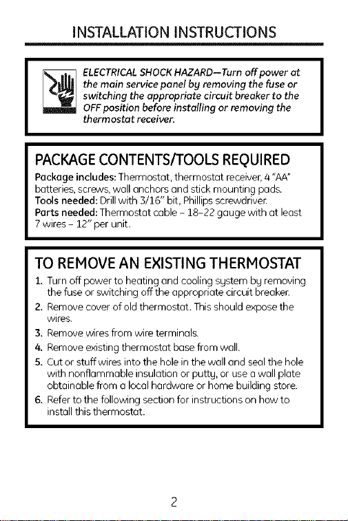
the main service panel by removing the fuse or
switching the appropriate circuit breaker to the
_ LECTRICALSHOCKHAZARD--Turn off power at
OFFposition before installing or removing the
thermostat receiver.
PACKAGE CONTENTS/TOOLS REQUIRED
Package includes: Thermostat, thermostat receiver,4 "AA"
batteries, screws, wall anchors and stick mounting pads.
Tools needed: Drillwith 3/16" bit, Phillipsscrewdriver.
Parts needed: Thermostat cable - 18-22 gauge with at least
7 wires - 12" per unit.
TO REMOVE AN EXISTING THERMOSTAT
1. Turn off power to heating and cooling system by removing
the fuse or switching off the appropriate circuit breaker.
2. Remove cover of old thermostat. Thisshould expose the
wires.
3. Remove wires from wire terminals.
4. Remove existing thermostat base from wall.
5. Cutor stuff wires into the hole in the wall and seal the hole
with nonflammable insulation or putty, or use awall plate
obtainable from a local hardware or home building store.
6. Referto the following section for instructions on how to
install this thermostat.
Page 3
INSTALLATION INSTRUCTIONS
INSTALLTHERMOSTAT(when mounting to clwall)
IMPORTANT: Thermostat installation must
conform to local and national building and electrical codes
and ordinances.
Note: Mount the thermostat about five feet above the floor. Do
not mount thethermostat on on outside wall, in direct sunlight,
behind o door or in on area affected bg o vent or duct.
MOUNT THE THERMOSTAT
i, Turnoff power to the heating and cooling sgstem bg
removing the fuse or switching off the appropriate circuit
breakeE
2. To remove the cover,using both hands, pressthe two
push-tabs on the bottom of the thermostat housing with
gour thumbs while pulling the front ofthe thermostat awag
from the base.
3. Put the thermostat base against the wall where gou plan
to mount it.
& Hark the placement of the mounting holes on the wall.
5. Set the thermostat base and cover awag from working
area.
6. Using a 3/16" drill bit, drill holes inthe locations gou have
marked for mounting.
7. Use a hammer to tap supplied anchors in mounting holes.
8. Align the thermostat base with mounting holesand use
supplied screwsto mount the thermostat base to wall.
9. Insert four "AA"batteries into the batterg holder.Verifg that
theg are oriented as shown on the batterg holder.
Page 4
INSTALLATION INSTRUCTIONS
INSTALL THE RECEIVER
2500, 2800, 3500 and 3800 SERIESZONELINE MODELS
the main service panel by removing the fuse or
switching the appropriate circuit breaker to the
ELECTRICALSHOCKHAZARD--Turn off power at
OFFposition before installing the thermostat
receiver.
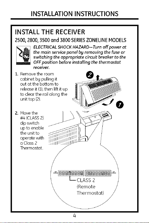
1, Remove the room
cabinet by pulling it
out at the bottom to
release it (1},then lift it up
to clear the railalong the
unit top (2}.
2. Move the
#4 (CLASS2)
dip switch
up to enable
the unit to
operate with
a Class 2
Thermostat.
\
_-CLASS 2
(Remote
Thermostat) j
Page 5
INSTALLATION INSTRUCTIONS
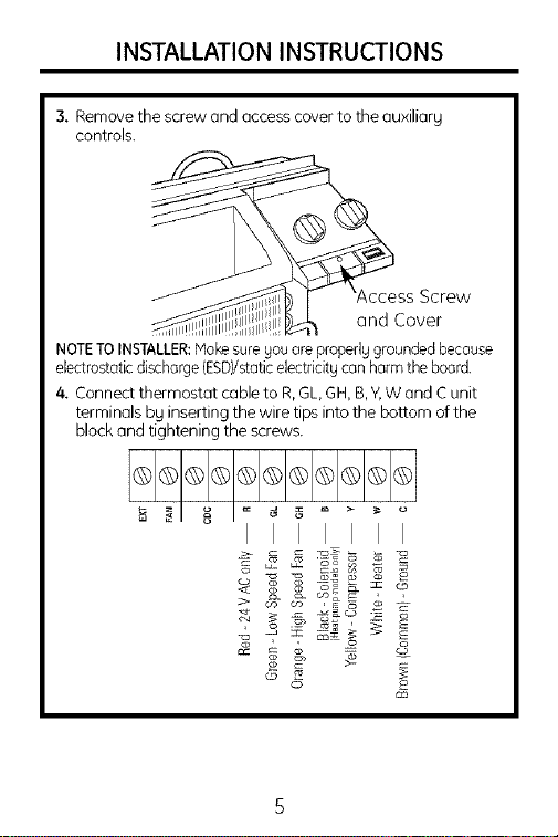
3, Remove the screw and access cover to the auxiliarg
controls.
Screw
and Cover
NOTETOINSTALLER:Nokesuregouare properlggroundedbecause
electrostaticdischarge(ESD)/staticelectricitgcan harmthe board.
4. Connect thermostat cableto R,GL,GH,B,Y,Wand Cunit
terminals bg inserting the wire tips into the bottom of the
block and tightening the screws.
I I
Page 6
INSTALLATION INSTRUCTIONS
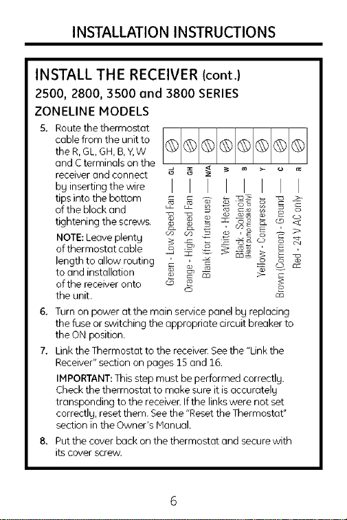
INSTALL THE RECEIVER (cont.)
2500, 2800, 3500 and 3800 SERIES
ZONELINE MODELS
5. Route the thermostat
cable from the unit to
the R, GL, GH, B,Y,W
and C terminals on the
receiver and connect d, _ _ _ ....
by inserting the wire
tips into the bottom _ _ ._-_ _ _ >-
of theblockand E _ _ _ _ -
tightening the screws. _ _ _ _ _ _ cD, >_:
NOTE: Leave plentg _ c_ _ _ o_ _
ofthermostatcable _ _ _ _ _ _'
length to allow routing _ _ -- (_ c_
to and installation _ _ _ >- =
of the receiver onto _
the unit.
6. Turn on power atthe main service panel by replacing
the fuse or switching the appropriate circuit breaker to
the ON position.
7. Link the Thermostat to the receiver. See the "Link the
Receiver" section on pages 15 and 16.
IMPORTANT: This step must be performed correctly.
Check the thermostat to make sure it is accurately
transponding to the receiver. If the links were not set
correctly, reset them. See the "Reset the Thermostat"
section in the Owner's Manual.
8. Put the cover back on the thermostat and secure with
its cover screw.
o
Page 7
INSTALLATION INSTRUCTIONS
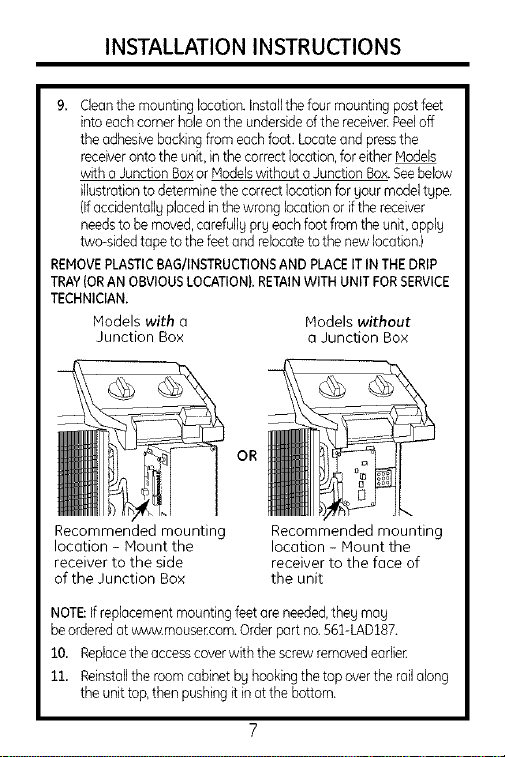
9. Cleanthe mountingIccation.Installthe four mountingpostfeet
intoeachcornerholeontheundersideofthe receiver.Peeloff
theadhesivebuckingfrom eachfoot. Locateandpressthe
receiveronto theunit,in thecorrectlocation,for eitherModels
with aJunctionBoxor Modelswithout aJunctionBox.Seebelow
illustrationtodeterminethe correctlocationforyour modeltgpe.
(Ifaccidentallyplacedinthe wrong locutionorif thereceiver
needstobemoved,carefull9 prgeachfoot from the unit,apply
two-sidedtape to the feetand relocatetothe newlocation.}
REMOVEPLASTICBAG/INSTRUCTIONSANDPLACEITINTHEDRIP
TRAY(ORANOBVIOUSLOCATION}.RETAINWITHUNITFORSERVICE
TECHNICIAN.
Models with a Models without
Junction Box a Junction Box
OR
Recommended mounting
location - Mount the
receiver to the side
of the Junction Box
Recommended mounting
location - Mount the
receiver to the face of
the unit
NOTE:Ifreplacementmountingfeetare needed,theg mag
beorderedatvfww.mouse_com.Orderpart no.561-LAD187.
10. Repbcethe accesscover with the screwremovodeariieE
11. Reinstallthe room cabinetby hookingthetop overtherailalong
theunittop,then pushingitin atthe bottom.
Page 8

INSTALLATION INSTRUCTIONS
INSTALL THE RECEIVER (cont.)
5500 and 5800 SERIES 70NELINE MODELS
the main service panel by removing the fuse or
switching the appropriate circuit breaker to the
_ LECTRICALSHOCKHAZARD--Turn offpowerat
OFF position before installing the thermostat
receiver.
1. Remove the room cabinet bg
pulling it out at the bottom to
release it (1), then lift it up to
clear the rail along the unit
top (2).
2. Movethe #4
(CLASS2)dip
switch up to
enable the unit
to operate with
a Class 2
Thermostat.
iX - CLASS 2 (Remote/
\\\
\
\
Thermo_._
Page 9

INSTALLATION INSTRUCTIONS
3, Remove the screws and access cover to the auxiliarg
controls.
Remove screws
and cover to
access terminal
connections
NOTETOINSTALLER:Hakesuregouore properlggroundedbecause
electrostaticdischarge(ESD)/staticelectricitgcan harmthe board.
4. Connect thermostat cableto R,GL,GH,B,Y,W and Cunit
terminals bg inserting the wire tips into the bottom of the
block and tightening the screws.
I I I I
> _ _co2E
, _ ®
o
Page 10

INSTALLATION INSTRUCTIONS
INSTALL THE RECEIVER (cont.)
5500 and 5800 SERIESZONELINE MODELS
S. Route the thermostat
cable from the unit,
under the right side of
the control wall and to
the R, GL, GH, B,Y,W
and C terminals on the
receiver. Connecttothe _ _ _ _ _ _ g
receiver by inserting _ _ _ 3:_2 _ _:
the wire tips into the _ __ _ , co_
bottornoftheblockand _ co = _ _o, _-_
tightening the screws. _ _-_ _ c_z _ _ -_
NOTE: Leave plenty _ _ _ _ _ cc
of thermostat cable _ _ >- z
length to allow routing cD o
to and installation of the
receiver onto the unit.
6. Turn on power atthe main service panel by replacing
the fuse or switching the appropriate circuit breaker to
the ON position.
7. Link the Thermostat to the receiver. See the "Link the
Receiver" section on pages 15 and 16.
IMPORTANT: This step must be performed correctly.
Check the thermostat to make sure it is accurately
transponding to the receiver. If the links were not set
correctly, reset them. See the "Reset the Thermostat"
section in the Owner's Manual.
8. Put the cover back on the thermostat and secure with
its cover screw.
_ _ >-
10
Page 11

INSTALLATION INSTRUCTIONS
9. Clean the mounting location. Install the four mounting
post feet into each corner hole on the underside of the
receiver. Peel off the adhesive backing from each foot.
Locate and press the receiver onto the unit, in the correct
location, for either Models with a Junction Box or Models
without a Junction Box. See below illustration to determine
the correct location for gour model tgpe. {If accidentallg
placed in the wrong location or if the receiver needs to
be moved, carefullg prg each foot from the unit, applg
two-sided tape to the feet and relocate to the new
location.)
Models with a
Junction Box
OR °_
Models without
a Junction Box
Recommended mounting
location - Mount the
receiver to the side
of the Junction Box
NOTE: If replacement mounting feet are needed, theg mag be
ordered at wvwv.mouser.com. Order part no. 561-LAD187.
10. Replace the access cover with the screw removed earlier
11. Reinstall the room cabinet bg hooking the top over the rail
along the unit top, then pushing it in at the bottom.
Recommended mounting
location - Mount the
receiver to the side of
the unit
11
Page 12

INSTALLATION INSTRUCTIONS
INSTALL THE RECEIVER Icont.)
7500 SERIES VERTICAL 70NELINE MODELS
themain servicepanel by removingthe fuseor switching
theappropriate circuit breakerto the OFFposition before
_ LECTRICALSHOCKHAZARD-Turnoffpowerot
installing thethermostat receiver.
1. Removethefront casepanel by removingthefilter,takingoutthe
four frontscrews,theuppertwo screwsfrom the topof the panel
andthe shippingscrewsoneachside,ifpresent.
Side
'-_ shipping
screw
shipping
screw
NOTETOINSTALLER:Makesuregouare properlggroundedbecause
electrostaticdischarge(ESD}/staticelectridtg canharmthe board.
2. Connectthermostatcane to R,GL,GH,B,Y,W andCunit
terminalsbg insertingthewire tipsintothe bottomofthe block
andtighteningthescrews.
c_ _
!2
Page 13

INSTALLATION INSTRUCTIONS
3. Route the
thermostat cable
from the unit
through the case
top cable opening
and connect to
the R, GL, GH, B,Y,
W and C terminals
on the receiver.
Connect the cable
to the receiver bg
inserting the
wire tips into
the bottom of
the block and
tightening the
screws.
I I I I I I II
13
Page 14

INSTALLATION INSTRUCTIONS
INSTALL THE RECEIVER (cont.)
7500 SERIES VERTICAL ZONELINE MODELS
4. Cleanthemountinglocation.
Installthefourmounting
postfeetintoeachcorner
holeontheundersideof
thereceive[Peeloff
theadhesive Recommended
backingfromeach mounting location -
foot.Locateand Mount the receiver
mountthereceiverto the case top
ontothecasetop
bypressingit intoposition.
(ifoccidentall9 placedin
thewronglocationorif the
receiverneedsto bemoved,
carefullypryeachfootfromNOTE:Ifreplacementmountingfeet
theunit,applytwo-sided areneeded,they may beorderedat
tapetothe feetand www.mouse:com.Orderpart no.
relocatetothe new 561-LAD187.
location.)
5. Turnon poweratthemainservicepanelbgreplacingthefuseor
switchingtheappropriatecircuitbreakertotheONposition.
6. LinktheThermostattothereceiveESeethe "LinktheReceiver"
sectiononpages15and16.
IMPORTANT:Thisstepmustbeperformedcorrectly.Checkthe
thermostatto makesureit isoccuratelgtranspondingtothereceiveE
Ifthelinkswerenotsetcorrectly,resetthem.Seethe"Resetthe
Thermostat"sectioninthe Owner'sManual.
7. Putthecoverbackonthe thermostatandsecurewithitscover
screw,
8. Replacethecasefrontpanelbyrepladngthefourfrontscrewsand
thetwotopscrews.
14
Page 15

INSTALLATION INSTRUCTIONS
LINK THE RECEIVER
The thermostat and receiver will not operate as a sgstem until
they are linked together through the installation process. The
linking process binds one or more receivers to a thermostat
so that they will communicate with each other as a control
system. Up to eight (8} receivers can be linked to a single
thermostat. Until linked, a control receiver will not operate.
Once linked, a control receiver will only respond to its specific
thermostat.
LINK THE THERMOSTAT TO THE RECEIVER
A thermostat and receiver that have been linked will not
interfere with or be affected bg ang other thermostat or
receiver in adjacent rooms, apartments or neighboring homes.
Linking information is stored in memorg-lt is not necessarg to
re-link a thermostat and receiver if the thermostat batteries are
removed or after a power outage.
If multiple installation teams ore installing and linking
thermostots at the some time coordinate the octivitg to ovoid
the possibilitg of installers simultaneously attempting to perform
the linking process. Because this is on RF system, instollers in
nearby rooms/oreos where it is possible RFoverlap could exist
run the risk of interfering with each othe_ Installation and linking
activity going on around o system already installed will not
interfere with it.
condnued on next page
15
Page 16
INSTALLATION INSTRUCTIONS
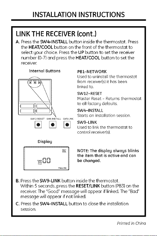
LINK THE RECEIVER(cont.)
A. Press the SW4-1NSTALL button inside the thermostat. Press
the HEAT/COOL button on the front of the thermostat to
select gour choice. Press the UP button to set the receiver
number (0-7) and press the HEAT/COOL button to set the
receive[.
Internal Buttons
J2
SW2RESET SW41NSTALL SWgLINK
Displag
PB1-NETWORK
Used to uninstall the thermostat
from receiver(s) it has been
linked to.
SW12-RESET
Master Reset - Returns thermostat
to allfactorg defaults
SW4-1NSTALL
Starts an installation session
SW9-LINK
Used to link the thermostat to
control receiver(s),
mr'l be changed.
'!_uu
B. Press the SW9-LINK button inside the thermostat.
Within 5 seconds, press the RESET/LINK button (PB3) on the
receive[. The "Good" message will appear if linked. The "Bad"
message will appear if not linked.
C. Press the SW4-1NSTALL button to close the installation
session.
the item that is active and can
12 NOTE:The displag alwags blinks
Printed in China
 Loading...