

Page 1
OWNER’S MANUAL &
INSTALLATION INSTRUCTIONS
RAK180W1
F
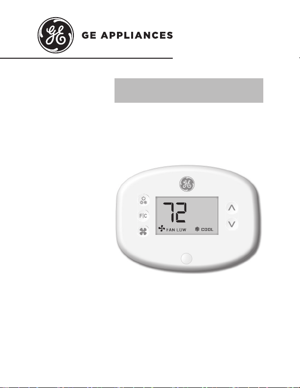
THERMOSTAT
Wireless Thermostat with Occupancy Sensor
49-5000416 Rev. 1 07-19 GEA
Page 2
THANK YOU FOR MAKING GE APPLIANCES A
PART OF YOUR HOME.
Whether you grew up with GE Appliances, or this is
your first, we’re happy to have you in the family.
We take pride in the craftsmanship, innovation and
design that goes into every GE Appliances product,
and we think you will too.
2 49-5000416 Rev. 1
Page 3

Table of Contents
Safety Information ............................................................................................................ 4
Before You Begin .................................................................................................................5
Thermostat Installation .................................................................................................... 7
Installing the Wireless Control card ........................................................................................7
Wireless Installation ...............................................................................................................10
Wired Installation ....................................................................................................................10
Thermostat Configuration ............................................................................................11
Setting the clock .....................................................................................................................12
Entering the room number ....................................................................................................13
Configuring the Equipment Settings - Compressor Type ....................................................14
Configuring the Equipment Settings - Electric Heat ............................................................15
Configuring the Equipment Settings - Reversing Valve ......................................................16
Configuring the Energy Saving Settings...............................................................................17
Custom Energy Savings Settings .............................................................................. 19
Using the Thermostat Settings Screens ...............................................................................20
01 – FAN CONTROL MODE ................................................................................................21
02 – 1ST STAGE DIFFERENTIAL - HEAT .........................................................................22
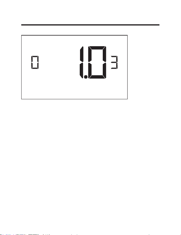
03 – 2ND STAGE DIFFERENTIAL - HEAT ........................................................................23
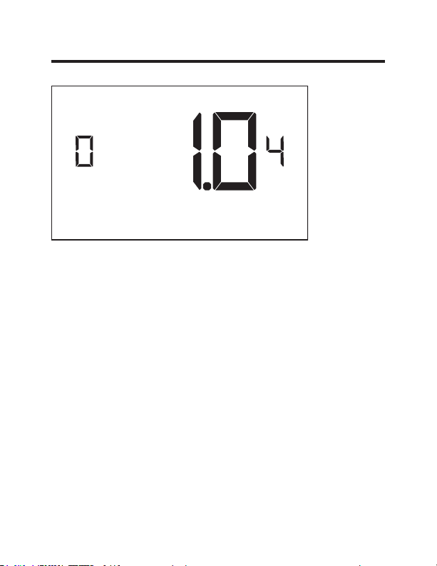
04 – 1ST STAGE DIFFERENTIAL - COOL ........................................................................24
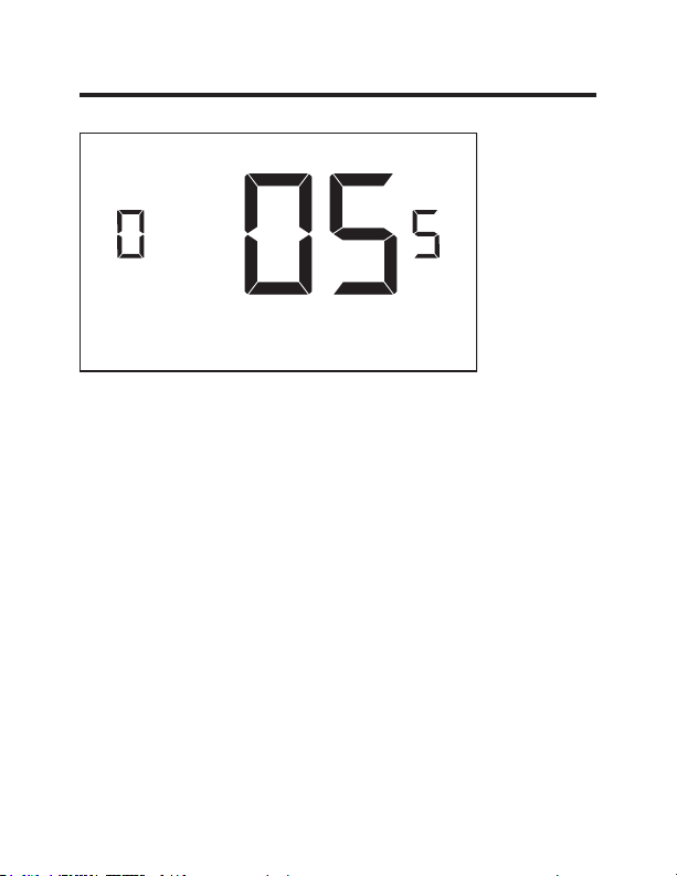
05 – INCIDENTAL OCCUPANCY THRESHOLD ...............................................................25
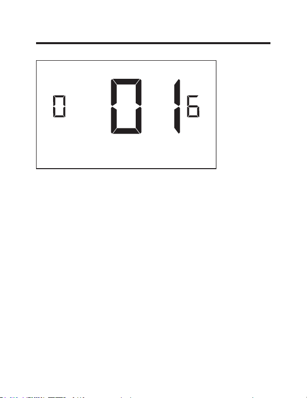
06 – NIGHT OCCUPANCY THRESHOLD ..........................................................................26
07 – FORCED 2ND STAGE HEATING ...............................................................................27
08 – NIGHT OCCUPANCY START .....................................................................................28
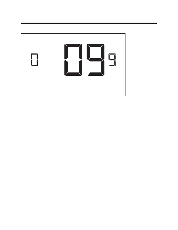
09 – NIGHT OCCUPANCY END .........................................................................................29
10 – TEMPERATURE RECOVERY TIME ..........................................................................30
11 – RECOVERY TEMPERATURE - HEAT .......................................................................31
12 – TEMPERATURE SETBACK DELAY - HEAT .............................................................32
13 – MINIMUM SETBACK TEMPERATURE ......................................................................33
14 – TEMPERATURE SETBACK DELAY - COOL ............................................................34
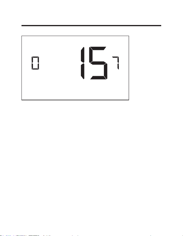
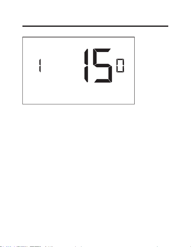
15 – MAXIMUM SETBACK TEMPERATURE.....................................................................35
16 – RECOVERY TEMPERATURE - COOL ......................................................................36
17 – MINIMUM SET POINT .................................................................................................37
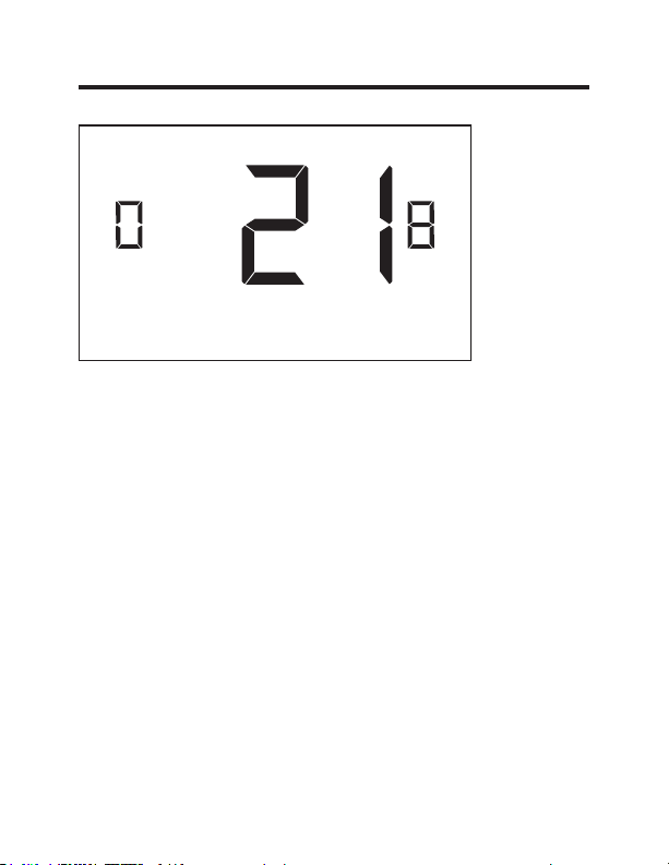
18 – MAXIMUM SET POINT ................................................................................................38
19 – TEMPERATURE CONTROL MODE ...........................................................................39
20 – AUTO CHANGEOVER SET POINT OFFSET
(DEAD BAND) ...............................................................................................................40
21 – SETBACK SET POINTS / AUTO-RESTORE .............................................................41
22 – AUTOMATIC HUMIDITY CONTROL† ........................................................................42
23 – TEMPERATURE CALIBRATION.................................................................................43
Thermostat Maintenance .............................................................................................44
Troubleshooting ................................................................................................................45
Appendix 1 - Energy Saving Presets ......................................................................48
Technical Specifications ..............................................................................................49
Limited Warranty ..............................................................................................................50
49-5000416 Rev. 1 3
Page 4

IMPORTANT SAFETY INFORMATION
READ ALL INSTRUCTIONS BEFORE USING
WARNING
• Always turn off power at the main power supply
before installing, cleaning or removing the
thermostat. Failure to do so could result in
electrical shock hazard.
• Do not use on voltages over 30 VAC. Higher
voltages will damage the thermostat and could cause
shock or fire hazard.
FIRE AND SHOCK HAZARD
NOTICE
• All wiring must conform to local and national
electrical and building codes.
• Use this thermostat only as described in this manual.
Specifications.
Electrical rating: • 24 VAC (18–30 VAC)
• 1 amp maximum per terminal
• 4 amp maximum total load
Operating temperature range: 40°F–99°F (4°C–37°C)
System Configurations:
* 1 stage cool, 2 stage heat (heat pump/resistance heat)
1 stage cool, 1 stage heat (resistance heat)
Terminations: *R, C, W, Y, GH, GL, B for 2-stage heat
R, C, W, Y, GH, GL, for 1-stage heat
Wiring:
*Default setting
4 49-5000416 Rev. 1
Maximum wiring length is 66ft (20 meters) for
AWG18
Maximum wiring length is 60ft (18 meters) for
AWG20
Page 5

Before You Begin
• Determine the appropriate installation location for the
thermostat
The thermostat should face the bed area of the
room.
The thermostat must not be installed near or on
metal structures or surfaces including metal air
ducting that may be in the wall.
0HWDOVWUXFWXUHVDQGVXUIDFHVVLJQL¿FDQWO\
reduce the range of the wireless signal.
A. Refer to the Zoneline Owner’s Manual to change
the AUX setting to 6A (class 2 mode). The unit will
display “use wall thermostat” when finished.
B. Zoneline output is 24VAC. Be sure the jumper on the
wireless control card is on the AC position – jumper
is connecting “R” and “C” (common) pins. This is the
default position.
Other Zoneline Auxilary Control Settings for use with
*DBM & *EBM Models
• Mode E: Enables Zoneline Makeup air vent door control
EDVHGRQRFFXSDQF\GHIDXOWLVRႇDQGPRGHPXVWEH
turned on to utilize this feature.
• Refer to the Zonelines Owner’s Manual for instructions
on how to change this AUX setting/mode.
49-5000416 Rev. 1 5
Page 6
NETWORK INSTALLATION ONLY
NOTE: This section is not required unless the thermostats are
networked
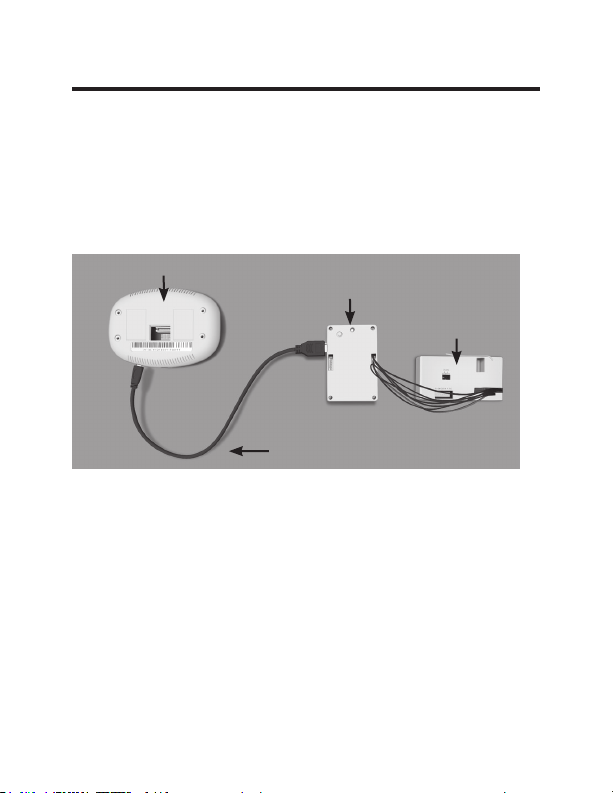
Pairing the Thermostat and the Control Card:
In case of Network Installation with online management, the
thermostat and the Control Card must be paired with a Network
Programmer specific to the property before the installation.
Note: Thermostat and Control Card are factory paired.
Thermostat
The thermostat and control card must not be powered during the
pairing procedure - remove batteries from the thermostat and unplug
the control card from the HVAC unit during the pairing procedure.
• Plug one programmer connector into the thermostat;
• Plug the other programmer connector into the control card.
• Push the black button on the programmer.
•
The red light on the programmer should turn on and remain
steadily lit.
•
If the red light on the programmer is blinking or is not steadily
lit, unplug the programmer from the thermostat and the control
card and repeat the steps above.
• Unplug the programmer from the thermostat and the control card.
6 49-5000416 Rev. 1
Network
Programmer
Programmer
Connector
Control
Card
Page 7
Thermostat Installation
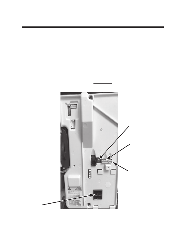
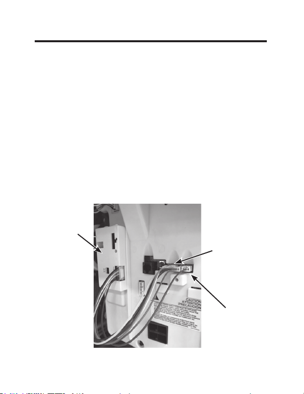
Installing the Wireless Control Card
• Power off the Zoneline
• Insert the Control Card wiring harness into the thermostat
connection port on the front of the Zoneline control box cover.
• For Makeup Air Models (*DBM and *EBM), insert the small
connector into the mating CDC Connection port next to the
thermostat port. (See Drawing 1)
NOTE: If not a Makeup Air Model, DO NOT plug in the CDC/
occupancy connection.
Red Aux Set
Button
Remote
Thermostat
Connection
CDC /
Occupancy
Connection
AC input
Drawing 1
49-5000416 Rev. 1 7
Page 8
Thermostat Installation
Installing the Wireless Control Card (cont.)
• Using the supplied double sided tape, attach the control card
to the Zoneline control box cover. (See Drawing 2)Mount the
control card inside of the hvac unit.
The wireless control card antenna must not be touching any metal
components of the hvac unit.
The wireless control card antenna must face the thermostat on the
wall and be oriented so that any metal parts of the Zoneline do not
obstruct the wireless communication to the thermostat and, in case of
a network installation, to other wireless control cards and the server.
The wireless control card must not be placed in the Zoneline
condensation pan and must be mounted so it cannot fall into the
condensation pan.
• For wired applications, join the common and 24VAC wires with
any code-approved low voltage field supplied connection method.
Control
Card
Remote
Thermostat
Connection
CDC/
Occupancy
Drawing 2
8 49-5000416 Rev. 1
Page 9
Thermostat Installation
Wiring Table – 24V AC
Wire Color Terminal Letter Terminal Connection
Black C Common
Red R 24V
Yellow Y Compressor
White W Heat
Orange O or B Reversing Valve
Green GH Fan High
Purple GL Fan Low
Brown AUX Occupancy
NOTE: If the PTAC unit has only one (1) fan speed,
connect both fan control wires – Green and Purple –
to the fan terminal (G).
49-5000416 Rev. 1 9
Page 10
GH OB W R Y C
AUX
GL
GH OB W R Y C
AUX
GL
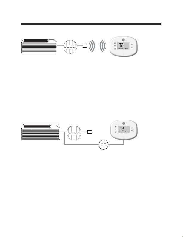
Thermostat Installation
Wireless Installation
F
Mounting the thermostat to the wall
• Remove the thermostat cover;
• Use the supplied wall anchors and mounting screws to
secure the thermostat to the wall;
• Insert two (2) AA-cell batteries (not supplied) into the
thermostat battery compartment;
• Follow the “Thermostat Configuration” instructions
starting on page 11.
• Replace the thermostat cover and screw in the locking
screw.
Wired Installation
F
R C
Mounting the thermostat to the wall
• Connect R & C from HVAC unit to the corresponding
wires on the harness by splicing 24VAC and common
wires from the thermostat into the 24VAC and common
wires to the zoneline.
• Remove the thermostat cover;
• Use the supplied wall anchors and mounting screws to
secure the thermostat to the wall;
• Follow the “Thermostat Configuration” instructions
starting on page 11.
• Replace the thermostat cover and screw in the locking
screw.
10 49-5000416 Rev. 1
Page 11
Thermostat Configuration
Once the thermostat is powered, thermostat configuration
settings will appear on the thermostat screen.
In order to properly operate the HVAC unit:
• Set the thermostat clock
• Enter the room number
• Configure the equipment settings
• Select Energy Savings Preset (Zoneline custom settings
are the default).
The thermostat configuration screens have a 30-second
time-out. If no action is taken within thirty (30) seconds, the
thermostat will exit configuration settings.
NOTE: You can
access Thermostat
Configuration settings at
any time by pressing the
“Configuration” button.
NOTE: If the thermostat is connected to a network, the
settings configured online will be applied.
49-5000416 Rev. 1 11
Page 12
Thermostat Configuration
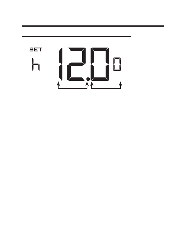
Setting the thermostat clock
Hours
Set the thermostat clock to current time in 24h (Military Time)
format.
• Use the “Up” and “Down” buttons to set the hours
• Press the “Fan” button to advance to the minutes setting
• Use the “Up” an “Down” buttons to set the minutes
• Press the “F/C” button to advance to the next menu
Setting the clock correctly is crucial for proper operation of
the thermostat.
The thermostat clock will need to be reset each time
NOTE:
the batteries are replaced.
12 49-5000416 Rev. 1
Minutes
Page 13
Thermostat Configuration
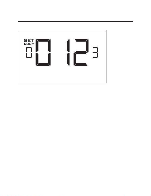
Entering the room number
Enter the room number by changing the digits on the screen.
Leading zeros “0” preceding other digits will be ignored, i.e.
Room number “123” should be entered as “00123”.
• Use the “Up” and “Down” buttons to change the digit;
• Press the “Fan” button to advance to the next digit;
• Press the “F/C” button to advance to the next menu;
Entering the room number correctly is crucial for proper
operation of networked systems.
49-5000416 Rev. 1 13
Page 14

Thermostat Configuration
Configuring the Equipment Settings - Compressor Type
Compressor Type
Use the “Up” and “Down” buttons to change the compressor
type by changing the first digit
0 - No Compressor
1* - Heat pump
2 - Air Conditioner
• Press the “Fan” button to advance to the next setting;
* Indicates default setting
If the Zoneline is an AZ45 model, change the
NOTE:
compressor type to a 2.
14 49-5000416 Rev. 1
Page 15

Thermostat Configuration
Configuring the Equipment Settings - Electric Heat
Electric Heat
Use the “Up” and “Down” buttons to change the Electric Heat
setting by changing the second digit;
0 - No Electric Heat- All Zonelines have Electric heat -
Do not select this option.
1* - Electric Heat
• Press the “Fan” button to advance to the next setting;
* Indicates default setting
49-5000416 Rev. 1 15
Page 16
Thermostat Configuration
Configuring the Equipment Settings - Reversing Valve
Reversing Heat
Use the “Up” and “Down” buttons to change the reversing
valve type by changing the first digit
0 - OB contact is energized to cool
1* - OB contact is energized to heat (default operation for
Zoneline heat pump models)
Refer to the HVAC unit documentation to determine the
correct OB VALVE setting.
If incorrect OB VALVE Setting is selected, the HVAC
unit will turn on the heating when air conditioning is
requested and turn on the air conditioning when heating is
requested.
• Press the “F/C” button to advance to the next menu
• Press the “Fan” button to advance to toggle to equipment
settings.
* Indicates default setting
NOTE: Zonelines OB is energized in heating mode.
16 49-5000416 Rev. 1
Page 17
Thermostat Configuration
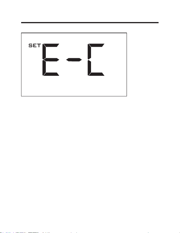
Configuring the Energy Saving Settings
Use the “Up” and “Down” buttons to select the Energy Saving
preset:
E-C*: Custom Energy Savings
•
Refer to the APPENDIX 1 on page 48 for Energy Saving
Preset details.
• For details on changing the custom settings, refer to the
“Custom Energy Savings Settings” section on page 19.
E-0: Energy Savings Off - No Temperature Setback;
E-1: Lowest Energy Savings;
E-2: Lower Energy Savings;
E-3: Standard Energy Savings;
E-4: Higher Energy Savings;
E-5: Highest Energy Savings;
• Press the “Power” button to save the Thermostat
Configuration and start using the thermostat.
* Indicates default setting
49-5000416 Rev. 1 17
Page 18

Thermostat Configuration
Testing the thermostat
Following the thermostat configuration, test if the thermostat
is controlling the Zoneline unit.
• Press the “Power” button to turn the thermostat ON;
• Press the “Down” button to change the temperature set
point below the current room temperature to confirm that
the thermostat initiates air conditioning.
• Press the “Up” button to change the temperature set point
above the current room temperature to confirm that the
thermostat initiates heating.
• Change the fan speed by touching the “Fan” button to test if
the thermostat is controlling the fan speed.
18 49-5000416 Rev. 1
Page 19
Custom Energy Savings Settings
This thermostat comes preprogrammed to use a custom
energy setting. To change any of these presets, follow the
instructions below.
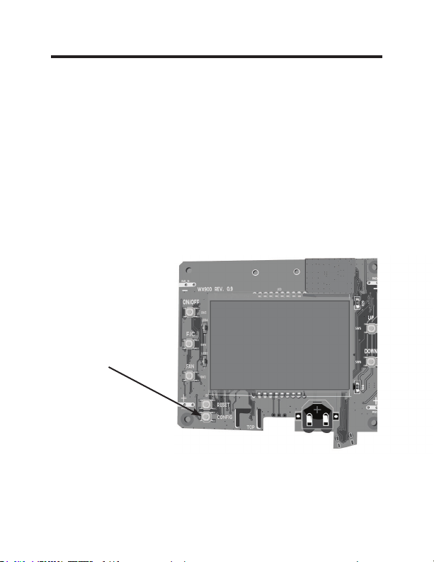
Accessing the Thermostat Settings
With the thermostat turned on, press and hold the
“Configuration” button until the first thermostat settings screen
appears. The thermostat must be turned on to access the
thermostat settings.
³&RQ¿JXUDWLRQ´EXWWRQ
NOTE: If the thermostat is connected to a network, the
settings configured online will be applied.
• Use the “Up” and “Down” buttons to change the setting;
• Press the “F/C” button to advance to the next setting;
• Press the “Fan” button to return to the previous setting;
• Press the “Power” button to save and exit thermostat
settings.
49-5000416 Rev. 1 19
Page 20
Custom Energy Savings Settings
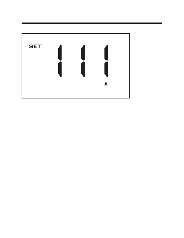
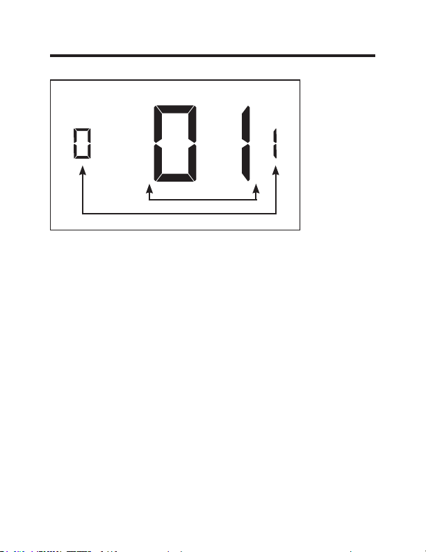
Using the Thermostat Settings Screens
Setting Value
Screen Number
• Use the “Up” and “Down” buttons to change the setting.
• Press the “F/C” button to advance to the next setting.
• Press the “Fan” button to return to the previous setting.
• Press the “Power” button to save and exit thermostat
settings.
The above is a representation of how to read the
digits on the thermostat screen.
20 49-5000416 Rev. 1
Page 21
Custom Energy Savings Settings
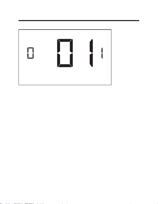
01 – FAN CONTROL MODE
Select Fan Control Mode:
00 - MANUAL - guest can select automatic or continuous
fan mode.
01* - AUTOMATIC - fan runs only when there is a
demand for heating or air conditioning.
* Indicates default setting.
49-5000416 Rev. 1 21
Page 22
Custom Energy Savings Settings
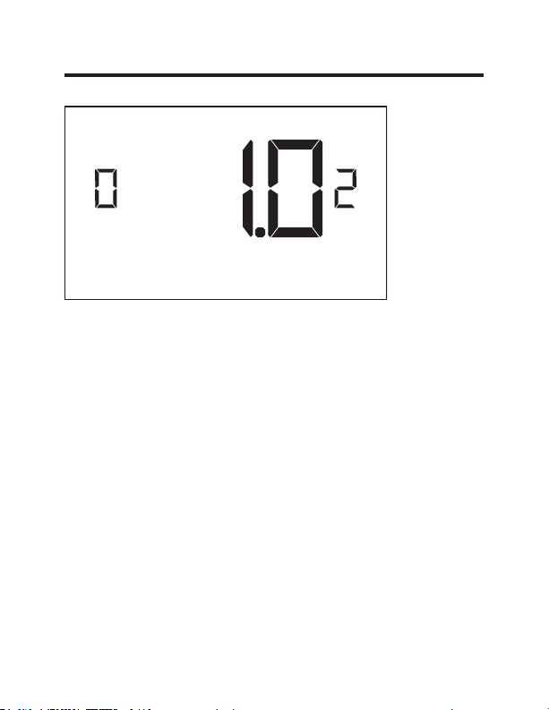
02 – 1ST STAGE DIFFERENTIAL - HEAT
(0.2°F - 3.0°F; 1.0°F* default setting) Select the number
of degrees** the thermostat has to sense between the
automatic changeover temperature for heat and the room
temperature before a call for the 1st stage heating is
initiated.
** above the dead band offset (refer to page 40)
22 49-5000416 Rev. 1
Page 23
Custom Energy Savings Settings
03 – 2ND STAGE DIFFERENTIAL - HEAT
(1.0°F - 2.0°F; 1.0°F* default setting) Select the difference
between 1st stage heating and 2nd stage heating
initiation.
49-5000416 Rev. 1 23
Page 24
Custom Energy Savings Settings
04 – 1ST STAGE DIFFERENTIAL - COOL
(0.2°F - 3.0°F; 1.0°F* default setting) Select the number
of degrees** the thermostat has to sense between the
automatic for cool and the room temperature before a call
for the 1st stage cooling is initiated.
**below the dead band offset (refer to page 40)
24 49-5000416 Rev. 1
Page 25
Custom Energy Savings Settings
05 – INCIDENTAL OCCUPANCY THRESHOLD
(00 - 60; 05* default setting) Select the minimum period of
time (in minutes) for which occupancy needs to be detected
to enter the guest occupancy mode.
When occupancy is detected, thermostat will switch to
occupied mode for a duration of “Incidental Occupancy
Threshold” selected here.
If occupancy is detected for a period of time shorter than
the “Incidental Occupancy Threshold” selected here, the
thermostat will automatically revert to unoccupied mode at
the end of the “Incidental Occupancy Threshold” period and
continue to observe energy saving functions that were in
effect before the room became occupied. This setting allows
ignoring incidental room visits.
If occupancy is detected for a period of time longer than
the “Incidental Occupancy Threshold” selected here, the
thermostat will enter the guest occupancy mode. When the
thermostat is in the guest occupancy mode, it will revert
to unoccupied mode and initiate the setback temperature
only when occupancy is not detected for the duration of the
setback delay (Heat or Cool) period.
49-5000416 Rev. 1 25
Page 26
Custom Energy Savings Settings
06 – NIGHT OCCUPANCY THRESHOLD
(00 - 60; 01* default setting) Select the minimum period of
time (in minutes) for which occupancy needs to be detected
in order to consider the room occupied during the “Night
Occupancy”period.
When occupancy is detected during the “Night Occupancy
Period” for longer than the “Night Occupancy Threshold”
selected here, the thermostat will instantaneously switch to
occupied mode.
If occupancy is detected for a period of time shorter than
the “Night Occupancy Threshold” selected here, the
thermostat will automatically revert to unoccupied mode and
continue to observe energy saving functions that were in
effect before the room became occupied.
If occupancy is detected for a period of time longer than the
“Night Occupancy Threshold” selected here, the thermostat
will disable the occupancy sensor and consider the room
occupied until the end of the “Night Occupancy” period.
This feature ensures that energy saving functions that may
affect guest comfort will not come in effect during the “Night
Occupancy” period.
26 49-5000416 Rev. 1
Page 27
Custom Energy Savings Settings
07 – FORCED 2ND STAGE HEATING
(00 - 60; 15* default setting) Select a number of minutes
1st stage heating will run before 2nd stage heating
is automatically initiated if the guest set point is not
reached and the 2nd stage heating is not initiated through
differential settings.
This feature allows automatically turning on 2nd stage
heating to avoid excessive compressor use.
Set to 00 to disable the feature.
49-5000416 Rev. 1 27
Page 28
Custom Energy Savings Settings
08 – NIGHT OCCUPANCY START
(00 - 23; 21* default setting) Select the start time (in hours
- 24-hour clock) for “Night Occupancy”
If occupancy is detected for a period of time longer
than the “Night Occupancy Threshold” during “Night
Occupancy” period, the thermostat will disable the
occupancy sensor and consider the room occupied until
the end of the “Night Occupancy” period.
This feature ensures that energy saving functions that
may affect guest comfort will not come in effect during
the “Night Occupancy” period if room was occupied for a
period of time longer than “Night Occupancy Threshold”.
28 49-5000416 Rev. 1
Page 29
Custom Energy Savings Settings
09 – NIGHT OCCUPANCY END
(00 - 23; 09* default setting) Select the time (in hours 24-hour clock) for “Night Occupancy” to end.
This is the time of day the “Night Occupancy” ends and
the thermostat switches back to the room sensing settings
chosen in the other occupancy modes.
49-5000416 Rev. 1 29
Page 30
Custom Energy Savings Settings
10 – TEMPERATURE RECOVERY TIME
(00 - 60; 15* default setting) Select the maximum time
allowed for a HVAC unit to attain temperature as defined
by Heat and Cool “Recovery Temperature”.
“Temperature Recovery Time” selected here and the actual
temperature recovery ability of the HVAC unit are used
to calculate setback temperatures. Calculated setback
temperatures maximize energy savings and at the same
time ensure that a comfortable room temperature (defined
as Heat and Cool “Recovery Temperature”) will be restored
within the selected “Temperature Recovery Time”.
Setting the “Temperature Recovery Time” to “00”, disables
temperature recovery. When temperature recovery is
disabled, thermostat will use the Minimum and Maximum
Setback Temperatures as setback set points.
30 49-5000416 Rev. 1
Page 31

Custom Energy Savings Settings
11 – RECOVERY TEMPERATURE - HEAT
(62°F - 82°F; 69°F* default setting) Select the room
temperature in °F that a HVAC unit will have to attain
within the selected “Temperature Recovery Time” when
there is a need for heating.
49-5000416 Rev. 1 31
Page 32

Custom Energy Savings Settings
12 – TEMPERATURE SETBACK DELAY - HEAT
(00 - 120; 30* default setting) Select the time delay
(in minutes) for which the room that is in the guest
occupancy mode needs to be unoccupied before the
temperature setback is initiated.
This feature prevents initiating temperature setback
prematurely while the guest is still in the room but in
an area where occupancy cannot be detected by the
occupancy sensor.
Setting the “Temperature Setback Delay - Heat” to “00”,
disables the setback in the heat mode.
32 49-5000416 Rev. 1
Page 33

Custom Energy Savings Settings
13 – MINIMUM SETBACK TEMPERATURE - HEAT
(52°F - 72°F; 65°F* default setting) Select the “Minimum
Setback Temperature” in °F.
Setback temperature is calculated by measuring HVAC
unit’s ability to attain “Recovery Temperature - Heat”
within “Temperature Recovery Time”.
If recovery is disabled (“Temperature Recovery Time” is
set to “0”) or if setback temperatures have not yet been
calculated, the “Minimum Setback Temperature” value will
be used as the setback temperature for heating.
If calculated setback temperature for heating is lower
than “Minimum Setback Temperature”, then the
“Minimum Setback Temperature” will be used as setback
temperature for heating.
This feature allows defining the minimum temperature in
a room when room is unoccupied and the thermostat is in
the setback mode.
49-5000416 Rev. 1 33
Page 34

Custom Energy Savings Settings
14 – TEMPERATURE SETBACK DELAY - COOL
(00 - 120; 30* default setting) Select the time delay
(in minutes) for which the room that is in the guest
occupancy mode needs to be unoccupied before the
temperature setback is initiated.
This feature prevents initiating temperature setback
prematurely while the guest is still in the room but in
an area where occupancy cannot be detected by the
occupancy sensor.
Setting the “Temperature Setback Delay - Cool” to “00”,
disables the setback in the cool mode. Set to “00” to
disable EMS.
34 49-5000416 Rev. 1
Page 35

Custom Energy Savings Settings
15 – MAXIMUM SETBACK TEMPERATURE - COOL
(72°F - 92°F; 76°F* default setting) Select the “Maximum
Setback Temperature” in °F.
Setback temperature is calculated by measuring HVAC
unit’s ability to attain “Recovery Temperature - Cool”
within “Temperature Recovery Time”.
If recovery is disabled (“Temperature Recovery Time” is
set to “0”) or if setback temperatures have not yet been
calculated, the “Maximum Setback Temperature” value
will be used as the setback temperature for cooling.
If calculated setback temperature for air conditioning is
higher than “Maximum Setback Temperature”, then the
“Maximum Setback Temperature” will be used as setback
temperature for air conditioning.
This feature allows defining the maximum temperature in
a room when room is unoccupied and the thermostat is in
the setback mode.
49-5000416 Rev. 1 35
Page 36

Custom Energy Savings Settings
16 – RECOVERY TEMPERATURE - COOL
(62°F - 82°F; 72°F* default setting) Select the room
temperature in °F that a HVAC unit will have to attain
within the selected “Temperature Recovery Time” when
there is a need for air conditioning.
36 49-5000416 Rev. 1
Page 37

Custom Energy Savings Settings
17 – MINIMUM SET POINT
(64°F - 84°F; 66°F* default setting) Select the minimum
set point in °F that a guest can select.
49-5000416 Rev. 1 37
Page 38

Custom Energy Savings Settings
18 – MAXIMUM SET POINT
(60°F - 82°F; 78°F* default setting) Select the maximum
set point in °F that a guest can select.
38 49-5000416 Rev. 1
Page 39

Custom Energy Savings Settings
19 – TEMPERATURE CONTROL MODE
Select Temperature Control Mode:
00 - MANUAL - Allows users to select HEAT only or
COOL only temperature control mode to maintain the
room temperature.
01* - AUTOMATIC - Thermostat automatically turns on
heating or air conditioning to maintain the room
temperature at the selected temperature set point.
* Indicates default setting
49-5000416 Rev. 1 39
Page 40

Custom Energy Savings Settings
20 – AUTO CHANGEOVER SET POINT OFFSET
(DEAD BAND)
(00°F - 04°F; 01°F* default setting) Select the difference
between the guest-selected set point and the heat and
the cool set point when the thermostat is in the automatic
temperature control mode.
This value plus the 1st stage differential defined in
steps 02 and 04, defines the temperature at which the
thermostat would automatically change heating/cooling
modes.
This feature allows adjusting the dead band between the
heat and the cool set points in automatic changeover
mode in order to avoid the system from bouncing back
and forth between heating and cooling under normal
operating conditions.
40 49-5000416 Rev. 1
Page 41

Custom Energy Savings Settings
21 – SETBACK SET POINTS / AUTO-RESTORE
Select Temperature Control Mode:
00 - When room is unoccupied and the thermostat is in the
setback mode or turned off, it will NOT maintain the
temperature between heat and cool setback set points
When guest enters the room, the thermostat will be turned off it will not automatically restore the most recent guest settings.
01 -
When room is unoccupied and the thermostat is in the setback
mode or turned off, it will maintain the temperature between
heat and cool setback set points.
When guest enters the room, the thermostat will be turned off - it
will not automatically restore the most recent guest settings.
02 - When room is unoccupied and the thermostat is in the
setback mode or turned off, it will NOT maintain the
temperature between heat and cool setback set points.
When guest enters the room, the thermostat will
automatically restore the most recent guest settings.
03* - When room is unoccupied and the thermostat is in the setback
mode or turned off, it will maintain the temperature between
heat and cool setback set points.
When guest enters the room, the thermostat will
automatically restore the most recent guest settings.
* Indicates default setting
49-5000416 Rev. 1 41
.
Page 42

Custom Energy Savings Settings
22 – AUTOMATIC HUMIDITY CONTROL
00 - Disable automatic humidity control
01* - Enable automatic humidity control
When “Automatic Humidity Control” is enabled,
thermostat will turn on air conditioning in an
unoccupied room when humidity raises above 60%
and room temperature is above 72°F until either
room humidity is below 55% or room temperature is
below 72°F.
* Indicates default setting
42 49-5000416 Rev. 1
Page 43

Custom Energy Savings Settings
23 – TEMPERATURE CALIBRATION
(-5.0°F - 5.0°F; 0.0°F* default setting) Calibrate the
temperature display: +/- 5.0°F
49-5000416 Rev. 1 43
Page 44

Thermostat Maintenance
Replacing Thermostat Batteries
The low battery indicator will be displayed on the
thermostat screen when it is necessary to replace batteries
in the thermostat.
Under normal operating conditions, new brand-name
alkaline batteries will last for a period of approximately one
(1) year.
Please replace batteries every twelve (12) months to
ensure continuous thermostat operation.
To replace thermostat batteries:
•
Remove the thermostat cover;
•
Replace the two (2) AA-cell batteries (not-supplied);
•
Replace the thermostat cover;
•
Follow the “Thermostat Configuration” instructions to set
the thermostat clock;
•
Press the “Power” button to start using the thermostat;
NOTE: The thermostat maintains all the “Thermostat
Configuration” settings in a non-volatile memory.
There is no need to configure the thermostat again
after battery replacement.
NOTE: While batteries are not required in a wired
installation, batteries should be installed to prevent
re-configuring the time on the thermostat if a power
failure occurs.
44 49-5000416 Rev. 1
Page 45

Troubleshooting
Error Codes
ERR1 - Thermostat Temperature Sensor Hardware Defect
ERR2 - Thermostat Radio Hardware Defect
ERR3 - Thermostat Radio Software Defect
ERR4 - No link with the Wireless Control Card
ERR5 - Thermostat Memory Defect
NOTES:
For ERR1, ERR2, ERR3, and ERR5, call GE Appliances
service. (Phone number located in Limited Warranty
section on page 50.
For ERR4, reset the configurations starting on page 5.
49-5000416 Rev. 1 45
Page 46

Troubleshooting
The thermostat is not controlling the HVAC unit.
Check if the HVAC unit is set to “External Thermostat”
(Class 2) mode. Refer to Zoneline Owner’s Manual, Aux
settings.
Verify the status of the red light on the Wireless Control
Card.
•
The red light is off
The Wireless Control Card is not powered. Verify that
the Wireless Control Card is properly wired to the HVAC
unit-specifically make sure that the RED and the BLACK
wire are properly connected.
•
If the red light is blinking with one (1) flash.
The Wireless Control Card is powered but it is not
communicating with the thermostat, turn the thermostat
off and on to re-initiate the linking procedure.
In case of a Network Installation, re-link the thermostat
and the Wireless Control Card with the Network
Programmer.
•
The red light is blinking with three (3) flashes.
The Wireless Control Card is communicating with the
thermostat. Verify that the Wireless Control Card is
properly wired to the HVAC unit and that equipment
settings on a thermostat - compressor type, electric heat
and reversing valve - are properly configured.
46 49-5000416 Rev. 1
Page 47

Troubleshooting
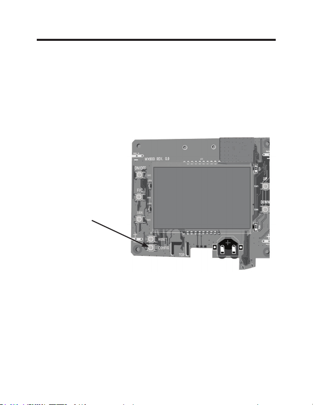
Initiating a Master Reset
If there are reported errors or configuration issues, the
user may master reset the thermostat to its default
parameters.
Procedure:
•
Remove the faceplate of the thermostat
•
Power down the thermostat by either removing the
batteries or cutting power to the thermostat.
•
While the thermostat is powered off, press and hold the
“config” button located on the control board inside the
thermostat.
• Restore power to the thermostat by reinstalling the
battieries.
• Once the screen lights up,
•
If the master reset was successful, the thermostat will
display “12:00”,indicating all settings will be reset to
default and the thermostat needs to be re-configured.
Please see “configuring thermostat” in the manual on
page 9.
Contact GE Appliances technical support at
1-844-GE4-PTAC (or 844-434-7822) if the issues are not
resolved.
release the “config” button.
49-5000416 Rev. 1 47
Page 48

Appendix 1 - Energy Saving Presets
Screen # Energy Level Default
012345 E-C
01 Fan Control Mode Auto Auto Auto Auto Auto Auto Auto
02 VW6WDJH'LႇHUHQWLDO+HDW 0.5 0.5 0.5 0.5 0.5 0.5 1.0
03 QG6WDJH'LႇHUHQWLDO
Heat
04 VW6WDJH'LႇHUHQWLDO&RRO 0.5 0.5 0.5 0.5 0.5 0.5 1.0
05 Guest Occupancy
Threshold
06 Night Occupancy
Threshold
07 Force 2nd Stage Heating
After
08 Night Occupancy Start 18 19 20 21 22 23 21
09 Night Occupancy End 12 11 10 9 8 7 09
10 Recovery Time 00 15 20 25 30 00 15
11 Recovery Temperature
Heat
12 Setback Delay - Heat 00 30 25 20 15 10 30
13 Minimum Setback
Temperature
14 Setback Delay - Cool 00 30 25 20 15 10 30
15 Maximum Setback
Temperature
16 Recovery Temperature
Cool
17 Minimum Set point 64 64 65 66 67 68 66
18 Maximum Set point 82 82 80 78 76 74 78
19 Temperature Control
Mode
20 Auto Changeover Set
Point
21 Setback Set Points /
Auto Restore
22 Automatic Humidity
Control
23 Temperature Calibration 0.0 0.0 0.0 0.0 0.0 0.0 0.0
1.0 1.0 1.0 2.0 2.0 2.0 1.0
00 05 05 05 05 05 05
01 01 01 01 01 01 01
30 30 30 30 30 30 15
70 69 68 67 66 65 69
67 66 65 64 63 62
72 74 76 78 80 82 76
71 72 73 74 75 76 72
Auto Auto Auto Auto Auto Auto Auto
01 01 01 01 01 01 01
OFF ON ON ON ON ON ON
ON ON ON ON ON ON ON
Setting
65
48 49-5000416 Rev. 1
Page 49

Technical Specifications
Thermostat Wireless Control Card
Case Dimensions (Imperial) 4.015 x 5.5118” x 0.925” 3.875” x 2.125” x 0.75”
Case Dimensions (Metric) 102mm x 140mm x
Screen Dimensions (Imperial) 3.625” x 2.125” N/A
Screen Dimensions (Metric) 92mm x 54mm N/A
Operating Voltage 3V DC - 2 “AA” Cell Bat-
Control Outputs Fan High (GH)
Occupancy Sensor Beam
Width
Wireless Frequency 900MHz 900MHz
Temperature Accuracy ±1°F N/A
FCC ID XEYWX XEYV8ACCC
23.5mm
teries OR(Optional) 24V
AC/DC
±47° (94°) N/A
FCC STATEMENT
This device complies with part 15 of the
fcc rules. Operation is subject to the
following two conditions: (1) this device
may not cause harmful interference, and
(2) this device must accept any interference received, including interference that may cause
undesired operation.
Pursuant to part 15.21 of the FCC rules, any changes or
PRGL¿FDWLRQVWRWKLVHTXLSPHQWQRWH[SUHVVO\DSSURYHGE\
GE Appliances may void the user’s authority to operate
the equipment.
98mm x 54mm x 19mm
24V AC/DC
Fan Low (GL)
Compressor (Y)
Heat Pump (OB)
Electric Heat (W2)
Occupancy Out (AUX)
49-5000416 Rev. 1 49
Page 50

THERMOSTAT LIMITED WARRANTY
Proof of the original purchase date is needed to validate the warranty.
For The Period Of: GE Appliances Will Replace:
One Year Full Replacement of the thermostat which fails
From the date of the due to a defect in materials or workmanship.
original purchase
For help with thermostat troubleshooting, call 1-844-GE4-PTAC
(or 844-434-7822)
What GE Appliances Will Not Cover:
Ŷ Service trips to your location.
Ŷ Improper installation. If you have an installation problem, contact your installer.
You are responsible for providing adequate electrical connections to the product.
Ŷ Failure of the product resulting from modifications to the product or due to
unreasonable use, including failure to provide reasonable and necessary
maintenance.
Ŷ
In commercial locations, labor necessary to move the unit, after it has been initially
installed, to a location where it is accessible for service by an individual technician;
or, if the instructions included in this manual have been disregarded.
Ŷ
Replacement of location fuses or the resetting of circuit breakers.
Ŷ Damage to the product caused by improper power supply voltage, accident, fire,
floods or acts of God.
Ŷ Incidental or consequential damage caused by possible defects with this
thermostat.
Staple your receipt here.
EXCLUSION OF IMPLIED WARRANTIES—
remedy is product exchange as provided in this Limited Warranty. Any implied
warranties, including the implied warranties of merchantability or fitness for a
particular purpose, are limited to one year or the shortest period allowed by law.
This limited warranty is extended to the original purchaser and any succeeding owner for
products purchased for use within the USA and Canada. In Alaska, the limited warranty
excludes the cost of shipping or service calls to your site.
Some states or provinces do not allow the exclusion or limitation of incidental or consequential
damages. This limited warranty gives you specific legal rights, and you may also have other
rights which vary from state to state or province to province. To know what your legal rights are,
consult your local, state or provincial consumer affairs office or your state’s Attorney General.
50 49-5000416 Rev. 1
Warrantor: GE Appliances, Louisville, KY 40225
Your sole and exclusive
Page 51

Manuel Du Propriétaire Et
Instructions D’installation
RAK180W1
F
THERMOSTAT
Thermostat avec détecteur de mouvements sans fil
49-5000416 Rev. 1 07-19 GEA
Page 52

MERCI D’AVOIR INTÉGRÉ GE APPLIANCES
DANS VOTRE FOYER.
Que vous ayez grandi avec GE Appliances ou que
ce soit votre premier achat, nous sommes heureux
de vous accueillir dans notre famille.
Nous sommes fiers de nos artisans, de l’innovation et
de la conception faisant partie de chaque produit GE
Appliances et nous croyons que vous le serez aussi.
2 49-5000416 Rev. 1
Page 53

Table des matières
Renseignements concernant la sécurité .............................................................. 4
Avant de commencer .........................................................................................................5
Installation du thermostat .................................................................................................. 7
Installation de la carte de commande sans fil ........................................................................7
Installation sans fil ..................................................................................................................10
Installation câblée .................................................................................................................10
Configuration du thermostat .........................................................................................11
Réglage de l’horloge ..............................................................................................................12
Inscription d’un numéro de pièce ..........................................................................................13
Configuration des réglages d’équipement – Type compresseur ........................................14
Configuration des réglages d’équipement – Chauffage électrique .....................................15
Configuration des réglages d’équipement - Robinet inverseur ...........................................16
Configuration des réglages d’économies d’énergie .............................................................17
Réglages personnalisés d’économies d’énergie ................................................ 19
Utilisation des écrans de réglages du thermostat ................................................................20
01 – MODE DE COMMANDE DU VENTILATEUR ............................................................21
02 – 1RE PHASE DIFFÉRENTIELLE– CHAUFFAGE .......................................................22
03 – 2E PHASE DIFFÉRENTIELLE– CHAUFFAGE ..........................................................23
04 – 1RE PHASE DIFFÉRENTIELLE– CLIMATISATION .................................................24
05 – SEUIL D’OCCUPATION OCCASIONNELLE .............................................................25
06 – SEUIL D’OCCUPATION NOCTURNE ........................................................................26
07 – 2E PHASE DE CHAUFFAGE À AIR PULSÉ .............................................................27
08 – DÉBUT D’OCCUPATION NOCTURNE ......................................................................28
09 – FIN D’OCCUPATION NOCTURNE .............................................................................29
10 – DÉLAI DE RÉTABLISSEMENT DE TEMPÉRATURE ...............................................30
11 – DÉLAI DE RÉTABLISSEMENT DE LA TEMPÉRATURE– CHAUFFAGE ..............31
12 – DÉLAI DE RETOUR AU POINT DE CONSIGNE DE TEMPÉRATURE – CHAUFFAGE
13 – RETOUR AU POINT DE CONSIGNE DE TEMPÉRATURE MINIMUM ..................33
14 – DÉLAI DE RETOUR AU POINT DE CONSIGNE DE LA TEMPÉRATURE – CLIMATISATION
15 – RETOUR AU POINT DE CONSIGNE DE TEMPÉRATURE MAXIMUM .................35
16 – RÉTABLISSEMENT DE LA TEMPÉRATURE – CLIMATISATION ..........................36
17 – VALEUR DE CONSIGNE MINIMUM ..........................................................................37
18 – VALEUR DE CONSIGNE MAXIMUM .........................................................................38
19 – MODE DE CONTRÔLE DE TEMPÉRATURE ...........................................................39
20 – COMMUTATION AUTOMATIQUE DU DÉCALAGE DE LA VALEURDE CONSIGNE
(ZONE MORTE) ............................................................................................................40
21 – RETOUR AUXVALEURS DE CONSIGNE/RESTAURATION AUTOMATIQUE .....41
22 – CONTRÔLE AUTOMATIQUE D’HUMIDITÉ...............................................................42
23 – ÉTALONNAGE DE TEMPÉRATURE .........................................................................43
Entretien du thermostat ..................................................................................................44
Dépannage ............................................................................................................................45
Annexe 1 –Économies d’énergie préréglées ..........................................................48
Spécifications ......................................................................................................................49
Garantie limitée ..................................................................................................................50
49-5000416 Rev. 1 3
..32
.....34
Page 54

RENSEIGNEMENTS IMPORTANTS
CONCERNANT LA SÉCURITÉ VEUILLEZ
LIRE TOUTES LES INSTRUCTIONS AVANT
L’UTILISATION.
AVERTISSEMENT
RISQUE D’INCENDIE ET D’ÉLECTROCUTION
• Veillez toujours à mettre l’alimentation électrique hors
tension depuis la source d’alimentation électrique
principale avant d’installer, de nettoyer ou de retirer le
thermostat. La désobéissance à ces directives représente
un risque d’électrocution.
• N’utilisez pas de tension supérieure à 30 VCA. Une tension
plus élevée endommagera le thermostat et causera un risque
d’électrocution ou d’incendie.
AVIS
• Tout le câblage doit être conforme aux Codes d’électricité
locaux, nationaux et aux Codes du bâtiment.
• Utilisez ce thermostat aux seules fins décrites dans ce
manuel.
Spécifications
Caractéristiques électriques nominales
• 24 VCA (18 à 30 VCA)
• 1 A maximum par borne.
• Total de 4 A maximum par circuit.
Gamme des températures de fonctionnement: 4 à 37 °C (40 à 99 °F).
Configurations du système :
* Phase 1 de climatisation, phase 2 de chauffage (pompe à chaleur/
chauffage par résistance)
phase 1 de climatisation, phase 1 de chauffage (chauffage par résistance).
Connexions : *R, C, W, Y, GH, GL, B pour chauffage à 2 phases.
R, C, W, Y, GH, GL pour chauffage à 1 phase.
Câblage : Longueur maximum de câblage de 20 m (66 pi) pour un fil de
calibre américain 18.
Longueur maximum de 18 m (60 pi) pour un fil de calibre américain 20.
*Réglage par défaut
4 49-5000416 Rev. 1
Page 55

Avant de commencer
• Déterminez l’emplacement d’installation approprié pour votre
thermostat.
Le thermostat doit faire face à l’air du lit de la pièce.
Le thermostat ne doit pas être installé sur ou près de
structures métalliques ou des conduits de circulation
d’air métalliques pouvant se trouver derrière le mur.
Les structures et surfaces métalliques peuvent réduire
FRQVLGpUDEOHPHQWODSRUWpHGXVLJQDOVDQV¿O
A. Consultez le manuel du propriétaire Zoneline pour modifier
le réglage de l’AUX à 6A (mode de classe 2). L’appareil
affichera « use Wall thermostat » (utilisez le thermostat
mural) à la fin du réglage.
B. La sortie de l’appareil Zoneline est de 24 VCA. Assurez-
vous que le cavalier de la carte de commande sans fil est
à la position « AC » (CA) et que le cavalier est relié aux
broches « R » et « C » (commun). Ceci est la position par
défaut.
Autres réglages de commande auxiliaire d’appareil Zoneline
utilisé avec les modèles *DBM et *EBM.
• Mode « E » : Activation de la commande de porte d’évent
d’aération d’appoint du modèle Zoneline basé sur la présence;
ce mode est inactif par défaut et doit être activé pour pouvoir
utiliser cette caractéristique.
• Consultez le manuel du propriétaire de l’appareil Zoneline pour
savoir comment modifier ce réglage ou mode AUX.
49-5000416 Rev. 1 5
Page 56

INSTALLATION RÉSEAUTÉE SEULEMENT
REMARQUE : Cette section n’est pas requise si vos thermostats
Jumelage du thermostat et de la carte de commande:
Pour une installation en réseau avec gestion en ligne, le thermostat et la
carte de commande doivent être jumelés avec le programmeur de réseau
spécifique de la propriété avant d’être installés.
Remarque: Le thermostat et la carte de commande ont été jumelés en
usine.
réseautés.
Thermostat
Programmeur
de réseau
Connecteur du
programmeur
Le thermostat et la carte de commande doivent être hors tension pendant
la procédure de jumelage. Retirez les piles du thermostat et débranchez
la carte de commande de l’appareil CVCA pendant la procédure de
jumelage.
• Raccordez un connecteur du programmeur au thermostat;
• Raccordez l’autre connecteur du programmeur à la carte de commande.
• Appuyez sur le bouton noir du programmeur.
• Le témoin rouge sur le programmeur devrait s’allumer et rester fixe.
• Si le témoin rouge du programmeur clignote ou n’est pas fixe, débranchez
le programmeur du thermostat et de la carte de commande et répétez les
étapes ci-dessus.
• Débranchez le programmeur du thermostat et de la carte de commande.
Carte de
commande
6 49-5000416 Rev. 1
Page 57

Installation du thermostat
Installation de la carte de commande sans fil
• Mettez l’appareil Zoneline hors tension.
• Insérez le faisceau électrique de la carte de commande dans le port
de connexion du thermostat situé devant le couvercle de la boite de
commande de l’appareil Zoneline.
• Pour les modèles avec aération d’appoint (*DBM et *EBM), insérez le
petit connecteur dans la prise de connexion homologue CIA près de la
prise du thermostat. (Consultez le dessin 1.)
REMARQUE : Si le modèle n’a pas d’aération d’appoint, NE PAS brancher
dans la prise du CIA/détecteur de mouvements.
Bouton de
réglage rouge
AUX
Connexion à
distance du
thermostat
Connexion
au CIA/
détecteur de
mouvements
Entrée CA
DESSIN 1
49-5000416 Rev. 1 7
Page 58

Installation du thermostat
Installation de la carte de commande sans fil (suite)
• Utilisez le ruban à deux faces fourni pour fixer la carte de commande au
couvercle de la boite de commande de l’appareil Zoneline. (Consultez
le dessin 2). Montez la carte de commande à l’intérieur de l’appareil
CVCA. L’antenne de la boite de commande sans fil ne doit pas toucher
aucun composant métallique de l’appareil CVCA. L’antenne de la carte
de commande sans fil doit faire face au thermostat mural et être orientée
de manière à ce que toutes parties métalliques de l’appareil Zoneline
n’obstruent pas la communication sans fil vers le thermostat et, pour une
installation en réseau, les autres cartes de commande sans fil vers le
serveur. La carte de commande sans fil doit être placée dans le bac de
condensation de l’appareil Zoneline et doit être montée de manière à ne
pas tomber dans le bac de condensation.
• Pour les applications câblées, raccordez les fils communs et les fils 24
VCA avec toute méthode de connexion de basse tension approuvée par
le Code et fournie sur place.
Carte de
commande
Téléconnexion
du thermostat
CIA/
détecteur de
mouvements
8 49-5000416 Rev. 1
Dessin 2
Page 59

Installation du thermostat
Tableau pour câblage – 24 VCA
Couleur du câble Lettre de borne Raccordement à la borne
Noir C Commun
Rouge R 24V
Jaune Y Compresseur
Blanc W &KDXႇDJH
Orange O or B Robinet inverseur
Vert GH Ventilateur – Vitesse élevée
Pourpre GL Ventilateur – Basse vitesse
Brun AUX Détecteur de mouvements
REMARQUE : Si le climatiseur monobloc terminal
n’est équipé qu’avec une (1) vitesse de ventilateur,
raccordez les câbles du ventilateur ensemble (vert et
pourpre) à la borne du ventilateur (G).
49-5000416 Rev. 1 9
Page 60

Installation du thermostat
GH OB W R Y C
AUX
GL
GH OB W R Y C
AUX
GL
Installation sans fil
F
Montage du thermostat au mur
• Retirez le couvercle du thermostat;
• Utilisez les ancrages muraux et les vis de montage fournis pour fixer le
thermostat au mur;
• Insérez deux (2) piles AA (non fournies) dans le compartiment de pile du
thermostat;
• Suivez les instructions du chapitre « Configuration du thermostat »
commençant à la page 11.
• Réinstallez le couvercle du thermostat et la vis dans la vis de blocage.
Installation câblée
F
R C
Montage du thermostat au mur
• Raccordez la RC de l’appareil CVCA aux câbles correspondants du
faisceau en entrelaçant les fils de 24 VCA et commun du thermostat aux
fils de 24 VCA et commun de l’appareil Zoneline.
• Retirez le couvercle du thermostat;
• Utilisez les ancrages muraux et les vis de montage fournis pour fixer le
thermostat au mur;
• Suivez les instructions du chapitre « Configuration du thermostat »
commençant à la page 11.
• Réinstallez le couvercle du thermostat et la vis dans la vis de blocage.
10 49-5000416 Rev. 1
Page 61

Configuration du thermostat
Dès que le thermostat est sous tension, les réglages de configuration du
thermostat apparaîtront à l’écran du thermostat.
Pour pouvoir bien faire fonctionner l’appareil CVCA :
• Réglez l’horloge du thermostat.
• Inscrivez le numéro de la pièce.
• Configurez les réglages d’équipement.
• Sélectionnez le préréglage d’économie d’énergie (les réglages
personnalisés de l’appareil Zoneline sont par défaut).
Les écrans de configuration du thermostat ont un délai d’attente de 30
secondes. Si aucune action n’est entreprise dans les 30 secondes, le
thermostat quittera les réglages de configuration.
REMARQUE :
Vous pouvez
accéder aux
réglages de
configuration
du thermostat
en tout tout en
appuyant sur
le bouton «
Configuration ».
REMARQUE : Si le thermostat est raccordé à un réseau, les réglages de
configuration en ligne seront appliqués.
49-5000416 Rev. 1 11
Page 62

Configuration du thermostat
Réglage de l’horloge du thermostat
Heures
Réglez l’horloge du thermostat à l’heure actuelle en utilisant
le format 24 h (de 0 à 24 h).
• Utilisez les flèches vers le haut et vers le bas pour régler
les heures.
• Appuyez sur le bouton « Fan » (ventilateur) pour
augmenter les minutes.
• Utilisez les flèches vers le haut et vers le bas pour régler
les minutes.
• Appuyez sur le bouton « F/C » pour passer au menu
suivant.
Le réglage précis de l’horloge est vital pour que le thermostat
fonctionne correctement.
REMARQUE : L’horloge du thermostat devra être réglée à
nouveau chaque fois que les piles sont remplacées.
12 49-5000416 Rev. 1
Minutes
Page 63

Configuration du thermostat
Inscription d’un numéro de pièce
Inscrivez le numéro de la pièce en modifiant les chiffres à
l’écran. Les zéros devant les autres chiffres seront ignorés.
Par exemple, le numéro de pièce « 123 » doit s’inscrire «
00123 ».
• Utilisez les flèches vers le haut et vers le bas pour
modifier le chiffre;
• Appuyez sur le bouton « Fan » (ventilteur) pour passer
au chiffre suivant;
• Appuyez sur le bouton « F/C » pour passer au menu
suivant;
L’inscription du numéro précis de la pièce est vitale pour que
les systèmes réseautés fonctionnent correctement.
49-5000416 Rev. 1 13
Page 64

Configuration du thermostat
Configuration des réglages d’équipement – Type de
compresseur
Type de compresseur
Utilisez les flèches vers le haut et vers le bas pour modifier le
type de compresseur en modifiant le premier chiffre.
0 = Sans compresseur
1* = Pompe à chaleur
2 = Climatiseur
• Appuyez sur le bouton « Fan » (ventilateur) pour passer
au réglage suivant;
* Indique un réglage par défaut
REMARQUE : Si votre appareil Zoneline est le modèle
AZ45, modifiez le type du compresseur comme étant un 2.
14 49-5000416 Rev. 1
Page 65

Configuration du thermostat
Configuration des réglages d’équipement – Chauffage
électrique
&KDXႇDJHpOHFWULTXH
Utilisez les flèches vers le haut et vers le bas pour modifier
le réglage de chauffage électrique en modifiant le deuxième
chiffre;
0 - Sans chauffage électrique – Tous les appareils
Zoneline sont équipés d’un chauffage électrique – Ne
sélectionnez pas cette option.
1* - Chauffage électrique
• Appuyez sur le bouton « Fan » (ventilateur) pour passer
au réglage suivant;
* Indique un réglage par défaut
49-5000416 Rev. 1 15
Page 66

Configuration du thermostat
Configuration des réglages d’équipement - Robinet
inverseur
Inversion de la chaleur
Utilisez les flèches vers le haut et vers le bas pour modifier le type de
robinet inverseur en modifier le premier chiffre.
0 - Contact de BS sous tension pour la climatisation
1* - Contact de BS sous tension pour le chauffage
(fonctionnement par défaut des pompes à chaleur Zoneline).
Consultez la documentation de votre appareil CVCA pour
déterminer le bon réglage du robinet inverseur.
Si le réglage du robinet inverseur est erroné, l’appareil CVCA
mettra le chauffage en marche pendant la demande de
climatisation et mettra la climatisation en marche lorsque le
chauffage est demandé.
• Appuyez sur le bouton « F/C » pour passer au menu suivant;
• Appuyez sur le bouton « Fan » (ventilteur) pour passer et
basculer vers les réglages d’équipement.
* Indique un réglage par défaut
REMARQUE : La boite de sortie des appareils Zoneline est
alimentée en mode de chauffage.
16 49-5000416 Rev. 1
Page 67

Configuration du thermostat
Configuration des réglages d’économie d’énergie
Utilisez les flèches vers le haut et vers le bas pour sélectionner
le préréglage d’économie d’énergie. E-C* = Économies d’énergie
personnalisées
•
Consultez l’annexe 1 de la page 48 pour voir les détails des
préréglages d’économie d’énergie.
• Consultez le chapitre « Réglages d’économies d’énergie
personnalisés » à la page 19 pour voir les détails concernant la
modification des réglages personnalisés.
E-0: Économies d’énergie inactives – Aucunretour au point de
consigne de température;
E-1: Économies d’énergie minimes;
E-2: Économies d’énergie moins importantes;
E-3: Économies d’énergies standards;
E-4: Économies d’énergie importante;
E-5: Économies d’énergie maximum;
• Appuyez sur le bouton « Power » (mise en marche) pour
sauvegarder la configuration du thermostat et commencer son
utilisation.
* Indique un réglage par défaut
49-5000416 Rev. 1 17
Page 68

Configuration du thermostat
Essai du thermostat
Après avoir effectué la configuration du thermostat, assurezvous que le thermostat contrôle l’appareil Zoneline.
• Appuyez sur le bouton « Power » pour mettre le
thermostat en marche;
• Appuyez sur la flèche vers le bas pour modifier la valeur
de consigne de la température sous la température
actuelle de la pièce tout en vous assurant que le
thermostat a commencé à refroidir la pièce.
• Appuyez sur la flèche vers le haut pour modifier la
valeur de consigne de la température au-delà de la
température de la pièce actuelle tout en vous assurant
que le thermostat a commencé à chauffer la pièce.
• Appuyez sur le bouton « Fan » (ventilateur) pour
modifier la vitesse du ventilateur et que le thermostat
contrôle la vitesse du ventilateur.
18 49-5000416 Rev. 1
Page 69

Réglages d’économies d’énergie personnalisés
Ce thermostat est doté d’un réglage d’économie d’énergie personnalisé
préprogrammé. Pour modifier l’un des préréglages, suivez les instructions
ci-dessous.
Accès aux réglages du thermostat
Pendant que le thermostat est en marche, appuyez et maintenez le bouton
« Configuration » enfoncé jusqu’à ce que le premier écran de réglages du
thermostat s’affiche. Le thermostat doit être fonctionnel pour pouvoir accéder
aux réglages de ce dernier.
Bouton
Configuration
REMARQUE: Si le thermostat est raccordé à un réseau, les
réglages de configuration en ligne seront appliqués.
• Utilisez les flèches vers le haut et vers le bas pour modifier le réglage;
• Appuyez sur le bouton « F/C » pour passer au menu suivant.
• Appuyez sur le bouton « Fan » (ventilateur) pour retourner au réglage
précédent;
• Appuyez sur le bouton « Power » (mise en marche) pour sauvegarder
les réglages du thermostat et quitter la configuration.
49-5000416 Rev. 1 19
Page 70

Réglages d’économies d’énergie personnalisés
Utilisation des écrans de réglages du thermostat
Valeur du réglage
Numéro à l’écran
• Utilisez les flèches vers le haut et vers le bas pour
modifier le réglage.
• Appuyez sur le bouton « F/C » pour passer au menu
suivant.
• Appuyez sur le bouton « Fan » (ventilateur) pour
retourner au réglage précédent.
• Appuyez sur le bouton « Power » (mise en marche) pour
sauvegarder les réglages du thermostat et quitter la
configuration.
L’illustration ci-dessus indique comment lire les
chiffres sur l’écran du thermostat.
20 49-5000416 Rev. 1
Page 71

Réglages d’économies d’énergie personnalisés
01 – MODE DE COMMANDE DU VENTILATEUR
Sélection du moteur de commande du ventilateur :
00 - MANUEL - l’invité peut sélectionner le mode de
ventilateur automatique ou en continu.
01* - AUTOMATIQUE - Le ventilateur fonctionne
seulement lors d’une demande de chauffage ou de
climatisation.
* Indique un réglage par défaut
49-5000416 Rev. 1 21
Page 72

Réglages d’économies d’énergie personnalisés
02 – 1ERE PHASE DIFFENTIELLE– CHALEUR
(Réglage par défaut de 0,2 - 3,0 °F; 1,0 °F*). Sélectionnez
le chiffre de degrés**. Le thermostat doit détecter entre la
température de commutation automatique pour la chaleur
et la température ambiante avant qu’un appel pour le
chauffage de 1re phase soit lancé.
** Au-delà de l’écart de la zone de sensibilité (consultez la
page 40)
22 49-5000416 Rev. 1
Page 73

Réglages d’économies d’énergie personnalisés
03 – 2E PHASE DIFFÉRENTIELLE - CHAUFFAGE
(Réglage par défaut 1,0 °F – 2,0 °F; 1,0 °F*) Sélectionnez
la différence entre la première phase de chauffage et le
déclenchement de la deuxième phase de chauffage.
49-5000416 Rev. 1 23
Page 74

Réglages d’économies d’énergie personnalisés
04 – 1RE PHASE DIFFÉRENTIELLE - CLIMATISATION
(Réglage par défaut de 0,2 - 3,0 °F; 1,0 °F*). Sélectionnez
le chiffre de degrés**. Le thermostat doit détecter entre
la température de commutation automatique pour la
climatisation et la température ambiante avant qu’un
appel pour le chauffage de 1re phase soit lancé.
**sous l’écart de la zone de sensibilité (consultez la page
40)
24 49-5000416 Rev. 1
Page 75

Réglages d’économies d’énergie personnalisés
05 – SEUIL D’OCCUPATION OCCASIONNELLE
(Réglage par défaut 00-60; 05*) Sélectionnez la durée minimum
(en minutes) à laquelle la présence doit être détectée avant
d’activer le mode d’occupation d’invité.
Lorsqu’une présence est détectée, le thermostat passera au
mode d’occupation pendant la durée du seuil d’occupation
occasionnelle sélectionnée ici.
Si une présence est détectée pendant une durée plus courte
que le seuil d’occupation occasionnelle sélectionnée ici, le
thermostat passera automatiquement au mode d’absence à la fin
de la période du seuil d’occupation occasionnelle et continuera
de respecter les fonctions d’économies d’énergie effectives au
moment où la pièce est devenue occupée. Ce réglage permet
d’ignorer les visites inopinées dans la pièce.
Si une présence est détectée pendant une durée plus longue que
le seuil d’occupation occasionnelle sélectionnée ici, le thermostat
passera au mode d’occupation d’invité. Lorsque le thermostat
est en mode d’occupation d’invité, il passera au mode d’absence
et déclenchera leretour au point de consigne de température
seulement en l’absence de détection d’une présence pendant
la durée de la période du délai de retour au point de consigne
(chauffage ou climatisation).
49-5000416 Rev. 1 25
Page 76

Réglages d’économies d’énergie personnalisés
06 – SEUIL D’OCCUPATION NOCTURNE
Réglage par défaut 00-60; 01*) Sélectionnez la durée minimum
(en minutes) à laquelle l’occupation doit être détectée de manière
en prendre en considération l’occupation d’une pièce pendant la
période du seuil d’occupation nocturne.
Si une présence est détectée pendant une période de seuil
d’occupation nocturne plus longue que le seuil d’occupation
nocturne sélectionnée ici, le thermostat passera automatique au
mode d’occupation.
Si une présence est détectée pendant une période de
seuil d’occupation nocturne plus courte que le seuil
d’occupation nocturne sélectionnée ici, le thermostat passera
automatiquement au mode d’absence et continuera de respecter
les fonctions d’économies d’énergie effectives au moment où la
pièce est devenue occupée.
Si une présence est détectée pendant une période de seuil
d’occupation nocturne sélectionnée ici, le thermostat désactivera
le détecteur de mouvements et considérera la pièce comme étant
occupée jusqu’à la fin de la période d’occupation nocturne.
Cette caractéristique a pour but de s’assurer que les fonctions
d’économies d’énergie ne nuiront pas au confort de l’invité
pendant la période d’occupation nocturne.
26 49-5000416 Rev. 1
Page 77

Réglages d’économies d’énergie personnalisés
07 – 2E PHASE DE CHAUFFAGE À AIR PULSÉ
(Réglage par défaut 00 - 60; 15*) Sélectionnez un nombre
de minutes pour la première phase de chauffage avant
que la deuxième phase de chauffage se déclenche
automatiquement si la valeur de consigne d’invité n’est
pas atteinte et que la deuxième phase de chauffage ne
passe pas aux réglages différentiels.
Cette caractéristique permet d’enclencher
automatiquement la deuxième phase de chauffage et éviter
une usure excessive du compresseur.
Réglez à « 00 » pour désactiver cette caractéristique.
49-5000416 Rev. 1 27
Page 78

Réglages d’économies d’énergie personnalisés
08 – DÉBUT D’OCCUPATION NOCTURNE
(Réglage par défaut 00 - 23; 21*) Sélectionnez l’heure (en
heures - horloge 24 h) du début d’occupation nocturne.
détectée pendant une période plus longue que le seuil
d’occupation nocturne, le thermostat désactivera le
détecteur de mouvements et considérera la pièce comme
étant occupée jusqu’à la fin de la période d’occupation
nocturne.
Cette caractéristique a pour but de s’assurer que les
fonctions d’économies d’énergie ne nuiront pas au confort
de l’invité pendant la période d’occupation nocturne si la
pièce est occupée pendant une période plus longue que le
seuil d’occupation nocturne.
28 49-5000416 Rev. 1
Page 79

Réglages d’économies d’énergie personnalisés
09 – FIN D’OCCUPATION NOCTURNE
(Réglage par défaut 00 - 23; 09*) Sélectionnez l’heure (en
heures - horloge 24 h) du début d’occupation nocturne.
C’est la période de la journée où l’occupation nocturne
se termine et que le thermostat passe aux réglages de
détection de la pièce sélectionnés dans les autres modes
d’occupation.
49-5000416 Rev. 1 29
Page 80

Réglages d’économies d’énergie personnalisés
10 – DÉLAI DE RÉTABLISSEMENT DE LA
TEMPÉRATURE
(Réglage par défaut 00 - 60; 15*) Sélectionnez la durée
maximum allouée à l’appareil CVCA pour obtenir les
températures définies par le délai de rétablissement de la
température pour le chauffage et la climatisation.
Le délai de rétablissement de la température sélectionné
ici et la capacité de rétablissement de température actuelle
de l’appareil CVCA sont utilisés pour calculer les points
de consigne de températures. Des points de consigne de
température calculés maximisent les économies d’énergie
et assurent en même temps qu’une température confortable
de la pièce (défini par le rétablissement de températurede
chauffage et de climatisation) sera rétablie selon les
paramètres sélectionnés pour la durée de rétablissement de la
température.
Réglez la durée de rétablissement de la température à «
00 » pour désactiver le rétablissement de la température.
Lorsque le rétablissement de la température est désactivé,
le thermostat utilisera les points de consignes minimum et
maximum comme valeurs de consigne.
30 49-5000416 Rev. 1
Page 81

Réglages d’économies d’énergie personnalisés
11 – RÉTABLISSEMENT DE LA TEMPÉRATURE -
CHAUFFAGE
(Réglage par défaut 62 °F –82 °F; 69 °F*) Sélectionnez
la température de la pièce en Farenheit(°F) que l’appareil
CVCA doit atteindre pendant le délai de rétablissement de
la température sélectionné pour répondre à une demande
de chauffage.
49-5000416 Rev. 1 31
Page 82

Réglages d’économies d’énergie personnalisés
12 – DÉLAI DE RETOUR AU POINT DE CONSIGNE DE
LA TEMPÉRATURE - CHAUFFAGE
(Réglage par défaut 00 - 120; 38*) Sélectionnez la durée
nécessaire du délai (en minutes) pour une pièce en
mode d’occupation d’invité avant que la pièce devienne
inoccupée avant d’enclencher le point de consigne de la
température.
Cette caractéristique évite le déclenchement prématuré
du point de consigne de la température pendant que
l’invité est encore dans la pièce, mais dans un endroit où
l’occupation ne peut pas être détectée par le détecteur de
mouvements.
Réglez le délai de rétablissement du point de consigne de
température de chauffage à « 00 » pour désactiver le point
de consigne du mode de chauffage.
32 49-5000416 Rev. 1
Page 83

Réglages d’économies d’énergie personnalisés
13 – RETOUR AU POINT DE CONSIGNE DE
TEMPÉRATURE MINIMUM
(Réglage par défaut 52 - 72 °F; 65°F*) Sélectionnez le retour au
point de consigne de température minimum en Farenheit(°F.)
Le point de consigne de la température est calculé en mesurant
la capacité de l’appareil CVCA à atteindre le rétablissement de la
température – chaleur à l’intérieur des paramètres de durée de
rétablissement de la température.
Si le rétablissement est désactivé (la durée de rétablissement
de la température réglé à « 0 ») ou si le point de consigne des
températures n’a pas été calculé, la valeur du point de consigne
de température minimum sera utilisée comme point de consigne
de température pour le chauffage.
Si le point de consigne de température de chauffage est inférieur
au point de consigne de température minimum, alors le point de
consigne de température minimum sera utilisé comme point de
consigne pour le chauffage.
Cette caractéristique permet de définir une température minimum
pour une pièce lorsque celle-ci est inoccupée et que le thermostat
est en mode de retour au point de consigne.
49-5000416 Rev. 1 33
Page 84

Réglages d’économies d’énergie personnalisés
14 – DÉLAI DE RETOUR AU POINT DE CONSIGNE DE
LA TEMPÉRATURE - CLIMATISATION
(Réglage par défaut 00 - 120; 30*) Sélectionnez la durée
nécessaire du délai (en minutes) pour une pièce en
mode d’occupation d’invité avant que la pièce devienne
inoccupée avant d’enclencher le point de consigne de la
température.
Cette caractéristique évite le déclenchement prématuré
du point de consigne de la température pendant que
l’invité est encore dans la pièce, mais dans un endroit où
l’occupation ne peut pas être détectée par le détecteur de
mouvements.
Réglez le délai de rétablissement du point de consigne de
température – Climatisation à « 00 » pour désactiver le
point de consigne du mode de climatisation. Réglez à « 00
» pour désactiver l’EMS.
34 49-5000416 Rev. 1
Page 85

Réglages d’économies d’énergie personnalisés
15 – RETOUR AU POINT DE CONSIGNE DE
TEMPÉRATURE MAXIMUM
(Réglage par défaut 72 - 92 °F; 76 °F*) Sélectionnez le retour au
point de consigne de température maximum en Farenheit(°F.)
Le point de consigne de la température est calculé en mesurant
la capacité de l’appareil CVCA à atteindre le rétablissement de
la température – refroidissement, à l’intérieur des paramètres de
durée de rétablissement de la température.
Si le rétablissement est désactivé (la durée de rétablissement
de la température réglé à « 0 ») ou si le point de consigne des
températures n’a pas été calculé, la valeur du point de consigne
de température maximum sera utilisée comme point de consigne
de température pour la climatisation.
Si le point de consigne de température de climatisation est
inférieur au point de consigne de température maximum, alors le
point de consigne de température maximum sera utilisé comme
point de consigne pour la climatisation.
Cette caractéristique permet de définir une température maximum
pour une pièce lorsque celle-ci est inoccupée et que le thermostat
est en mode de retour au point de consigne.
49-5000416 Rev. 1 35
Page 86

Réglages d’économies d’énergie personnalisés
16 – RÉTABLISSEMENT DE LA TEMPÉRATURE -
CLIMATISATION
(Réglage par défaut 62 °F – 82°F; 72 °F*). Sélectionnez
la température de la pièce en Farenheit (°F) que l’appareil
CVCA doit atteindre pendant le délai de rétablissement de
la température sélectionné pour répondre à une demande
de climatisation.
36 49-5000416 Rev. 1
Page 87

Réglages d’économies d’énergie personnalisés
17 – VALEUR DE CONSIGNE MINIMUM
(Réglage par défaut 64 °F – 84 °F; 66 °F*) Sélectionnez
une valeur de consigne en Farenheit(°F) minimum que
l’invité peut sélectionner.
49-5000416 Rev. 1 37
Page 88

Réglages d’économies d’énergie personnalisés
18 – VALEUR DE CONSIGNE MAXIMUM
(Réglage par défaut 60 °F – 82 °F; 78 °F*). Sélectionnez
une valeur de consigne en Farenheit(°F)maximum que
l’invité peut sélectionner.
38 49-5000416 Rev. 1
Page 89

Réglages d’économies d’énergie personnalisés
19 – MODE DE CONTRÔLE DE TEMPÉRATURE
Sélections de mode de contrôle de température:
00 - MANUEL - Permet aux utilisateurs de sélectionner
les modes de contrôle de température pour
CHAUFFAGE ou CLIMATISATION seulement afin de
maintenir la température de la pièce.
01* - AUTOMATIQUE - Le thermostat déclenche
automatique le chauffage ou la climatisation afin de
maintenir la température de la pièce à la valeur de
consigne de température sélectionnée.
* Indique un réglage par défaut
49-5000416 Rev. 1 39
Page 90

Réglages d’économies d’énergie personnalisés
20 – COMMUTATION AUTOMATIQUE DU DÉCALAGE
DE LA VALEUR DE CONSIGNE (ZONE MORTE)
(Réglage par défaut 00 °F – 04 °F; 01 °F*) Sélectionnez
la différence entre la valeur de consigne sélectionnée
pour l’invité et la valeur de consigne pour le chauffage
et la climatisation lorsque le thermostat est en mode de
contrôle de température automatique.
Cette valeur plus la première phase différentielle définie
aux étapes 02 et 04, définissent la température à laquelle
le thermostat devrait automatiquement passes aux modes
de chauffage ou de climatisation.
Cette caractéristique permet de régler la zone morte entre
les valeurs de consigne de chauffage et de climatisation
en mode de commutation automatique afin d’éviter le
passage du chauffage à la climatisation du système sous
des conditions normales de fonctionnement.
40 49-5000416 Rev. 1
Page 91

Réglages d’économies d’énergie personnalisés
21 – RETOUR AUX VALEURS DE CONSIGNE/
RESTAURATION AUTOMATIQUE
Sélection du mode de contrôle de température :
00 - 00 - Lorsque la pièce est inoccupée et que le thermostat est en mode
de valeur de consigne ou désactivé, ce dernier ne maintiendra PAS
la température entre les valeurs de consigne du chauffage et de la
climatisation.
Lorsque l’invité entre dans la pièce, le thermostat sera désactivé – il ne
récupérera pas automatiquement les derniers réglages d’invité.
01 - Lorsque la pièce est inoccupée et que le thermostat est en mode de
point de consigne ou désactivé, ce dernier maintiendra la température
entre les valeurs de consigne du chauffage et de la climatisation
Lorsque l’invité entre dans la pièce, le thermostat sera désactivé – il
ne récupérera pas automatique les derniers réglages d’invité.
02 - Lorsque la pièce est inoccupée et que le thermostat est en mode
de point de consigne ou désactivé, ce dernier ne maintiendra PAS
la température entre les valeurs de consigne du chauffage et de la
climatisation.
Lorsque l’invité entre dans la pièce, le thermostat récupérera
automatiquement les derniers réglages d’invité.
03* - Lorsque la pièce est inoccupée et que le thermostat est en mode de
point de consigne ou désactivé, ce dernier maintiendra la température
entre les valeurs de consigne du chauffage et de la climatisation
Lorsque l’invité entre dans la pièce, le thermostat récupérera
automatiquement les derniers réglages d’invité.
* Indique un réglage par défaut
49-5000416 Rev. 1 41
Page 92

Réglages d’économies d’énergie personnalisés
22 – CONTRÔLE AUTOMATIQUE D’HUMIDITÉ
00 - Pour désactiver le contrôle automatique d’humidité
01* - Pour activer le contrôle automatique d’humidité
Lorsque le contrôle automatique d’humidité est
activé, le thermostat déclenchera la climatisation
dans une pièce inoccupée lorsque le taux d’humidité
est au-delà de 60 % et que la température est
inférieure à 72 °F jusqu’à ce que le taux d’humidité
soit inférieur à 55 % ou que la température de la
pièce est inférieure à 72 °F.
* Indique un réglage par défaut
42 49-5000416 Rev. 1
Page 93

Réglages d’économies d’énergie personnalisés
23 – ÉTALONNAGE DE TEMPÉRATURE
(Réglage par défaut -5,0 °F - 5,0 °F; 0,0 °F*). Affichage de
la température d’étalonnage : +/- 5,0 °F.
49-5000416 Rev. 1 43
Page 94

Entretien du thermostat
Remplacement des piles du thermostat
Le témoin de pile faible s’affichera sur l’écran du
thermostat lorsque ces dernières doivent être remplacées.
Sous des conditions de fonctionnement normales, une
nouvelle marque de piles alcalines durera environ un (1)
an.
Veuillez remplacer les piles chaque 12 mois pour assurer
un fonctionnement continu de votre thermostat.
Pour remplacer les piles du thermostat :
•
Retirez le couvercle du thermostat;
•
Insérez deux (2) piles AA (non fournies);
•
Réinstallez le couvercle;
•
Suivez les instructions de configuration du thermostat
pour régler l’horloge du thermostat;
•
Appuyez sur le bouton « Power » pour mettre le
thermostat en marche;
REMARQUE : Ce thermostat conserve tous ses réglages
de configuration dans une mémoire non volatile. Il ne sera
pas nécessaire de reconfigurer le thermostat après avoir
remplacé les piles.
REMARQUE : Comme les piles ne sont pas requises pour
une installation câblée, des piles doivent être installées
pour éviter la reconfiguration de l’horloge du thermostat en
cas de panne de courant.
44 49-5000416 Rev. 1
Page 95

Dépannage
Codes d’erreur
ERR1 - La quincaillerie du détecteur de température du
thermostat est défectueuse.
ERR2 - La quincaillerie de télécommunication du
thermostat est défectueuse.
ERR3 - Le logiciel de télécommunication du thermostat est
défectueux.
ERR4 - Lien non établi avec la carte de commande sans
fil.
ERR5 - Mémoire du thermostat défectueuse.
REMARQUES :
Communiquez avec le Service de GE Appliances lorsque
les erreurs ERR1, ERR2, ERR3 et ERR5 s’affichent. (Le
numéro de téléphone se trouve dans la section de la
garantie limitée, page 50).
Pour l’ERR4, reconfigurez les réglages en commençant à
la page 5.
49-5000416 Rev. 1 45
Page 96

Dépannage
Ce thermostat ne contrôle pas l’appareil CVCA.
Assurez-vous que l’appareil CVCA est réglé sous le mode
« Thermostat externe » (clase 2). Consultez les réglages
AUX dans le manuel d’utilisation de l’appareil Zoneline.
Vérifiez l’état du témoin rouge sur la carte de commande
sans fil.
•
Le témoin rouge est éteint.
La carte de commande sans fil n’est pas sous tension.
Assurez-vous que la carte de commande sans fil est
câblée correctement à l’appareil CVCA spécifique et
que les câbles ROUGE et NOIR sont correctement
raccordés.
•
Si le témoin rouge produit un (1) clignotement
La carte de commande sans fil est sous tension, mais
ne communique pas avec le thermostat; éteignez et
rallumez le thermostat pour réinitialiser la procédure de
jumelage.
Pour une installation en réseau, effectuez une nouvelle
liaison du thermostat et de la carte de commande sans fil
avec le programmeur réseau.
•
Le témoin rouge produit trois (3) clignotements.
La carte de commande sans fil communique avec le
thermostat. Assurez-vous que la carte de commande
sans fil est correctement câblée à l’appareil CVCA et
que les réglages d’équipement sur le thermostat (type
de compresseur, de chauffage électrique et de robinet
inverseur) sont configurés correctement.
46 49-5000416 Rev. 1
Page 97

Dépannage
Restauration aux paramètres d’usine
Si des problèmes d’erreurs ou de configuration se
produisent, l’utilisateur peut restaurer le thermostat aux
paramètres d’usine.
Procédure
• Retirez la plaque frontale du thermostat
•
Mettez le thermostat hors tension en enlevant les
piles ou en débranchant le thermostat de la source
d’alimentation électrique.
•
Pendant que le thermostat est hors tension, appuyez et
maintenez le bouton « config » situé sur le tableau de
contrôle à l’intérieur du thermostat.
• Rétablissez l’alimentation électrique du thermostat en
réinstallant les batteries.
• Dès que l’écran s’allume, relâchez le bouton « config ».
•
Si la restauration aux paramètres d’usine réussit,
le thermostat affichera « 12 h » indiquant que tous
les réglages par défaut ont été réinitialisés et que le
thermostat doit être reconfiguré. Veuillez consulter le
chapitre « Configuration du thermostat » à la page 9 du
manuel.
Communiquez avec le soutien technique de GE
Appliances au 1 844 -GE4-PTAC (ou 1 844 434-7822) si
les problèmes ne sont pas résolus.
49-5000416 Rev. 1 47
Page 98

Annexe 1 - Préréglages d’économies d’énergie
Écran
no
01
Mode de commande du ventilateur
02
5HSKDVHGLႇpUHQWLHOOH±
FKDXႇDJH
03
(SKDVHGLႇpUHQWLHOOH±FKDXႇDJH
04
5HSKDVHGLႇpUHQWLHOOH±FOLPDtisation
05
Seuil d’occupation occasionnelle
06
Seuil d’occupation nocturne
07
(SKDVHGHFKDXႇDJHjDLUSXOVp
08
Début d’occupation nocturne
09
Fin d’occupation nocturne
10
Délai de rétablissement de
température
11
Délai de rétablissement de la
WHPSpUDWXUH±FKDXႇDJH
12
Délai de retour au point de con-
VLJQHGHWHPSpUDWXUH±FKDXႇDJH
13
Retour au point de consigne de
température minimum
14
Délai de retour au point de
consigne de la température –
climatisation
15
Retour au point de consigne de
température maximum
16
Rétablissement de la température
– climatisation
17
Valeur de consigne minimum
18
Valeur de consigne maximum
19
Mode de contrôle de température
20
Commutation automatique du
décalage de la valeurde consigne
(zone morte)
21
Retour auxvaleurs de consigne/
restauration automatique
22
Contrôle automatique d’humidité
23
Étalonnage de température
Niveau d’énergie Réglage
par défaut
0 1 23 45 E-C
Auto Auto Auto Auto Auto Auto Auto
0.5 0.5 0.5 0.5 0.5 0.5 1.0
1.0 1.0 1.0 2.0 2.0 2.0 1.0
0.5 0.5 0.5 0.5 0.5 0.5 1.0
00 05 05 05 05 05 05
01 01 01 01 01 01 01
30 30 30 30 30 30 15
18 19 20 21 22 23 21
12 11 10 9 8 7 09
00 15 20 25 30 00 15
70 69 68 67 66 65 69
00 30 25 20 15 10 30
67 66 65 64 63 62 65
00 30 25 20 15 10 30
72 74 76 78 80 82 76
71 72 73 74 75 76 72
64 64 65 66 67 68 66
82 82 80 78 76 74 78
Auto Auto Auto Auto Auto Auto Auto
01 01 01 01 01 01 01
OFFON ONON ONONON
ON ON ON ON ON ON ON
0.0 0.0 0.0 0.0 0.0 0.0 0.0
48 49-5000416 Rev. 1
Page 99

Spécifications
Thermostat &DUWHGHFRPPDQGHVDQV¿O
Dimensions du boitier (mesure impériale) 4.015 x 5.5118” x 0.925” 3.875” x 2.125” x 0.75”
Dimension du boitier (mesure métrique) 102mm x 140mm x 23.5mm 98mm x 54mm x 19mm
Dimensions de l’écran (mesure impériale) 3.625” x 2.125” S.O.
Dimensions de l’écran (mesure métrique) 92mm x 54mm S.O.
tension de fonctionnement 3V DC - 2 “AA” Cell Batteries
Sorties d’asservissement Ventilateur - Élevé (GH)
Largeur du faisceau du détecteur de
mouvements
)UpTXHQFHVDQV¿O 900MHz 900MHz
Précision de température ±1°F S.O.
FCC ID XEYWX XEYV8ACCC
OR(Optional) 24V AC/DC
±47° (94°) S.O.
ÉNONCÉ DE LA FCC
Ce dispositif est conforme aux dispositions
fonctionnement est soumis aux deux conditions suivantes : (1)
Cet appareil ne doit pas provoquer d’interférences nuisibles; (2)
Cet appareil doit tolérer les interférences reçues, y compris celles
susceptibles de provoquer des opérations non désirées.
En vertu de la section 15.21 des règlements de la FCC, tout
FKDQJHPHQWRXWRXWHPRGL¿FDWLRQjFHWpTXLSHPHQWQRQH[SUHVsément approuvé par GE Appliances peut annuler le droit de
l’utilisateur d’utiliser cet équipement.
de la section 15 des règles de la FCC. Son
24V AC/DC
Ventilateur - Faible (GL)
Compresseur (Y)
Pompe à chaleur (BÉ)
&KDXႇDJHpOHFWULTXH:
Sortie pour occupation
(AUX)
49-5000416 Rev. 1 49
Page 100

GARANTIE LIMITÉE DU THERMOSTAT
Brochez votre reçu ici. Une preuve de la date d’achat originale est nécessaire pour
Période de la garantie : GE Appliances remplacera :
Un (1) an
À compter de la date un défaut de matériaux ou de fabrication.
du premier achat.
Pour obtenir de l’aide concernant les problèmes, appelez au 1 844 GEA-PTAT (ou 1
844 434-7822).
Ce que GE Appliances ne couvre pas :
Ŷ Frais de déplacement pour réparation vers votre emplacement.
Ŷ Une installation mal effectuée. Si vous avez un problème d’installation,
communiquez avec votre installateur. Vous êtes responsable d’effectuer
correctement les raccords électriques de votre produit.
Une défectuosité du produit causée par des modifications au produit ou par son
Ŷ
usage déraisonnable, y compris le défaut d’effectuer des entretiens raisonnables
et nécessaires.
Ŷ Dans les locaux commerciaux, la main-d’œuvre nécessaire pour déplacer l’appareil, après
son installation initiale, à un endroit où il est accessible pour l’entretien par un technicien
individuel; ou, si les instructions contenues dans ce manuel n’ont pas été respectées.
Ŷ Le remplacement des fusibles ou l’enclenchement des disjoncteurs du site.
Ŷ Les bris du produit causés pour une tension d’alimentation électrique inadéquate,
un accident, un incendie, les inondations et les cas de force majeure.
Les dommages accessoires ou immatériels causés par des probabilités de
Ŷ
défectuosités avec ce thermostat.
EXCLUSION DES GARANTIES IMPLICITES - Votre seul et unique recours
est l’échange du produit comme prévu dans cette garantie limitée. Toute
garantie implicite, y compris les garanties implicites de qualité marchande
ou d’adaptation à un usage particulier, est limitée à un (1) an ou à la
période la plus courte permise par la loi.
Cette garantie limitée est consentie à son premier acheteur et à tout propriétaire
subséquent pour les produits achetés pour utilisation aux États-Unis et au Canada. En
Alaska, la garantie limitée exclut les frais d’expédition ou les appels de service vers votre
site. Certains États ou provinces n’autorisent pas l’exclusion ou la limitation des dommages
accessoires ou immatériels. Cette garantie limitée vous donne des droits légaux
spécifiques, et vous pouvez également avoir d’autres droits qui varient d’un état ou d’une
province à l’autre. Pour connaître vos droits légaux, consultez votre bureau d’information
aux consommateurs local, provincial ou d’État ou le procureur général de votre État.
Garant : GE Appliances, Louisville, KY 40225
50 49-5000416 Rev. 1
valider la garantie.
Remplacement complet du thermostat comportant
 Loading...