

Page 1
Installation instructions
for your new
RAB-71 Standard
or Extended Room
Air Conditioner Case
Before you begin—Read these instructions completely and carefully.
IMPORTANT—OBSERVE ALL GOVERNING CODES AND ORDINANCES.
Note to Installer—Be sure to leave these instructions with the Consumer.
Note to Consumer—Keep these instructions with your Use and Care Book for future reference.
1
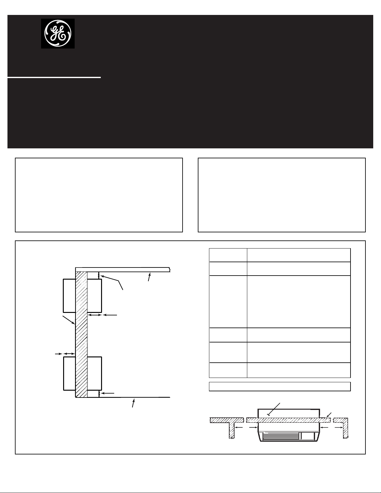
Critical Dimensions
Note:
Care should be taken in location of electrical supply
entry in relationship to wall sleeve to assure access
to power once the unit is installed.
Ceiling
“A”
“B”
“C”
Roomside
Outside wall
“D”
Finished floor or top of carpet
Recommended
Dimensions Installation Clearance
A Top of case to finished
ceiling – 3″ min.
B Projection of case into
room – 0″ min. (no sub-base)
2
3
⁄8″ min. when
sub-base is used.
If more than 6″ of the case
projects into the room, a
sub-base or other support
is recommended.
C Projection of case to
outside – 1/4″ min.
D Height above finished floor or top
of carpet – 0″ min. without sub-base
3″ min. with sub-base
E Left/Right side of case to
adjacent wall – 2″ min.
Top of case
Outside wall
“E”
“E”
Pub. No. 30-7795-2
04-00 JR
INSTALL CASE LEVEL IN ALL DIRECTIONS
Note:
• Handle the case carefully.
• The cardboard stiffener inside the case, and the rear
protective panel must remain in place until the chassis
is installed to assure case rigidity and squareness.
• If a sub-base is to be used, it may be desirable to
assemble it to the case before securing the case in
the wall.
Case location
As a general rule the air conditioner should be
located in an outside wall to assure proper
distribution of conditioned air. It should be located
in a portion of the wall where there is no electrical
wiring or plumbing, and where there are no
obstructions immediately inside or outside.
Page 2
STEP 1
Preparation of the wall
The wall case should be installed during construction
and lintels should be used to support the block above
the wall case. The case will not support the concrete
block or brick. The case is modular in height and
width:
Height — Fits 2 courses concrete block
— Fits 6 courses standard brick
— Fits 5 courses jumbo brick
Width — Fits approximately 3 stud spaces.
For existing construction, wall openings must be
made. Wall openings of the proper dimensions are
essential to avoid the necessity of fillers or additional
framing.
Note:
Use lintel to support brick, block, etc. above the air
conditioner case. (If directly under a window sill the
use of a lintel may not be necessary.)
2
STEP 2
Preparation of the case
Do not remove the cardboard stiffener inside the
case until the chassis is installed.
If field supplied case angles are to be used and must
be installed, proceed as follows:
1. Position the case angles around top and sides of
the case at the desired location (front to rear) with
angles facing toward rear (outside). Position the
case angles vertically on each side of the case to
provide a level installation.
2. Mark the case through the holes in the case angles.
3. Drill 5/32″diameter holes at marked locations
on the case and assemble the angles using only
10×1/2″ screws. Install the screws from the
outside of the case.
4. Do not drill any holes in bottom of the case.
Case
Case angle
Block
Roomside
Brick
Main stud
Jack studs
Jack stud
Cripple
Finished floor
Sub-floor
“D”*
Adjust
framing
to secure
this
dimension
(*See chart
on page 1)
Header—4″×4″ or
2—2″×4″ on edge
16
1
⁄4″ Min.
42
1
⁄4″ Min.
MINIMUM
FINISHED
OPENING
DIMENSIONS CASE DIMENSIONS
Height Width Height Width Depth
16
1
⁄4″ 421⁄2″
16″ 42″ 133⁄4″16″ 24″ 28″ 31″
16
1
⁄4″ 421⁄4″
Using
Case Angles
NOT Using
Case Angles
Page 3

3
STEP 3
Installation of the case in the wall opening
1. Position the case into the wall. Refer to chart on
page 1 for roomside projection. The rear (outside)
edge of the case should extend at least 1/4″
beyond the outside wall to be able to caulk
properly and prevent sealing the drain holes in the
rear flange of the case, and to facilitate easy
installation of an accessory drain, if desired. (If it is
desired to have the rear grille flush on the outside,
a drip rail must be installed under the case, and
caulking applied between the drip rail and case.)
Important:
Install case level from left to right and level from
roomside to the outside.
2. Firmly secure the case to wall structure. Do not
drill any holes in the bottom of the case.
3. Caulk the entire opening on the outside between
the case and the building exterior.
4. Caulk the entire opening on the inside between
the case and the building interior.
Use lintel, when required, to support brick and block
above the case.
Note:
Do not drill any holes in the case for electrical
connections. See the Owner’s Manual for how to
connect the electrical supply.
STEP 4
Weather proofing
Weather proof gaps between the exterior and
interior walls and the case with caulking or
equivalent weather proofing material.
Stiffener
Inside wall
Secure
case
thru
side or
top only
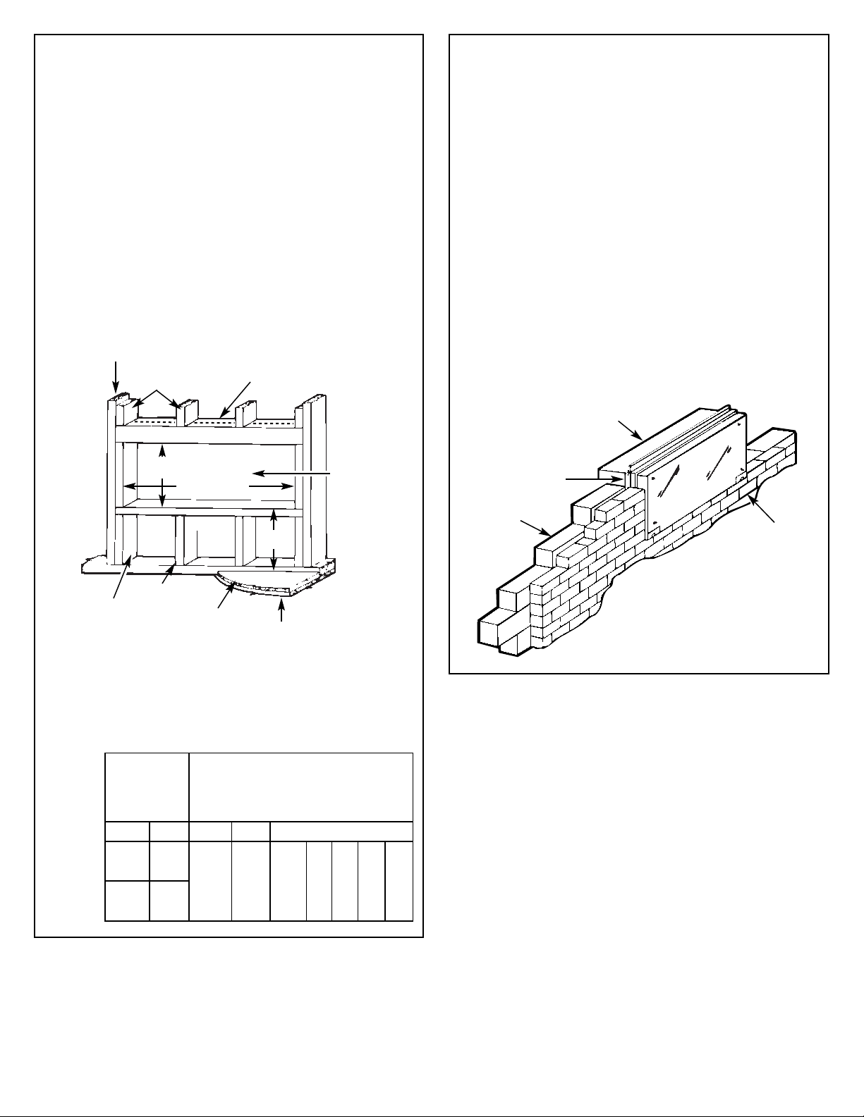
For installation in extra thick walls
1. If the case is being installed in a thick wall where
the case is recessed more than 3″, an extended
wall case will be required with depths as called
out in the table in Step 1.
2. If the case is being installed in a wall where the
recess is 3″ or less, and an extended wall case is
not used, flashing must be installed under the
case and extend up 2″ on each side. The flashing
must include a drip rail as illustrated in the figure
below.
3. For further details, refer to the “GE Architects and
Engineers Design Data Manual” for Zonelines. To
obtain a copy of that manual, call the GE Answer
Center® at 800.626.2000.
*Caulk around perimeter of wall case on all
four sides on the outside and the roomside
where it joins the building.
Caulk*
Steel
lintel
Caulk*
Outdoor
grille
Room
cabinet
Caulk*
Case
Caulk*
Finished floor or
top of carpet
Outdoor
grille
Flashing
Drip rail
Case
Caulk*
*Caulk around perimeter of wall case on all four
sides where it joins the building.
Page 4

4
DRAIN KIT
If it is necessary to install a drain kit on this wall
case, the following kit is available:
RAD10 Internal/External Drain
1. With an “Internal Drain”, the condensate drain
tube must be connected to an internal drain
system in the building.
2. With an “External Drain” (which may be connected
to a field supplied drain line) condensate water can
be drained away from the unit and building.
Note:
It may be desirable or necessary to install the
drain kit on the case prior to installing the case into
the wall.
WALL CASE WITH RAD10 DRAIN UNIT
INTERNAL DRAIN
WALL CASE WITH RAD10 DRAIN UNIT
EXTERNAL DRAIN
SCREW
Type “A”
METAL
Specifications subject to change without notice
A Quality Product of GE Appliances
ELECTRICAL REQUIREMENTS (230/208V)
Provisions should be made to have the proper
electrical outlet near the case. All wiring should be
made in accordance with local codes and
regulations. The line cord included with the chassis
(if used) will extend to a wall receptacle located
within the area shown in tabulation below.
Wall Receptacles
All wiring should be made in accordance with local
electrical codes and regulations.
See the Owner’s Manual for how to connect
electrical supply.
Note:
Aluminum wiring in structure may pose special
problems—consult a qualified electrician.
“A”
Inside
“B”
Model “A” “B”
AZ Series 21″ 58″
230V/208V 15 amp
230V/208V 20 amp 230V 30 amp
“tandem” type “perpendicular” type “tandem” type
ELECTRICAL REQUIREMENTS (265V)
Warning:
Connection of a 265V product to a branch circuit
MUST
be done by direct connection to be in
compliance with the National Electric Code.
Plugging a 265V unit directly into a building
mounted exposed receptacle is not permitted by
code.
See the Owner’s Manual for how to connect
electrical supply.
See detail
below
Overflow relief drain
Neoprene sponge gasket
Steel mounting plate
Type “A” screws
Square drain holes
Speed nuts
Type “A” screws
Gasket
Tube
1/2
″ O.D.
Cover plate
Cabinet bottom
Overflow relief drains
1/2″ O.D. drain tube
Square drain holes
Neoprene sponge gasket
Steel mounting plate
Type “A” screws
Alternate
6″ long, 1/2″
O.D. straight
copper tube.
 Loading...