

Page 1

CARESCAPE R860
Quick Reference Guide
Software Revision 10
Page 2

User responsiblity
Refer to the User's Reference manual for step-by-step instructions. Read
each component's User's Reference manual before using this system. All
Warnings and Cautions are in the User's Reference Manual.
WARNING
Before using this system:
• Complete all of the preoperative tests.
• Test all other system components.
Page 3

Introduction
Introduction
Welcome
Thank you for choosing the GE Healthcare CARESCAPE® R860. Our
goal is to provide you with the highest quality product and services
available. This ventilator features a user interface specifically designed to
streamline workflow while providing exceptional insight into patient
needs.
Measured data definitions
Patient monitoring views show patient data measured by the ventilator
and accessories.
Note
Some measured data can be viewed with different units. Set unit
preferences on the Configuration > Units menu. See "Configuring units"
in the "System configuration (Super User) and service" section.
Note
Some data is only available when an airway module with the required
capabilities, such as spirometry and metabolics, is installed and warmed
up.
.
Gases Data Definition Unit
FiO2 The percentage of oxygen that the
ventilator delivers to the patient.
EtO2 The percentage of oxygen exhaled,
measured at the end of expiration.
EtCO2 The percentage of carbon dioxide exhaled,
measured at the end of expiration.
FI-ET O2 The difference between inspiratory and
expiratory concentrations of oxygen.
.
Pulmonary Data Definition Unit
C The compliance of the patient’s respiratory
system measured during the breath cycle.
Cstat The static compliance of the patient’s
respiratory system measured during an
inspiratory hold.
2065492-001 1
%
%
%, kPa, or mmHg
%
ml/cmH2O, ml/
kPa, or ml/mbar
ml/cmH2O, ml/
kPa, or ml/mbar
Page 4

Pulmonary Data Definition Unit
Raw The average inspiratory and expiratory
airway resistance measured during the
breath cycle.
PEEPe+i The sum of extrinsic and intrinsic positive
end expiratory pressures.
Time Constant The time needed for the lungs to deflate by
cmH2O/l/s,
kPa/l/s, or
mbar/l/s
cmH2O, kPa, or
mbar
ms
a certain amount or a percentage of
volume.
• One Time Constant allows 63% of
volume to be exhaled.
• Two Time Constants allow for 86% of
volume to be exhaled.
• Three Time Constants allow for 95%
of volume to be exhaled.
• Four Time Contants allow for 98% of
volume to be exhaled.
Static PEEPi The pressure above PEEPe that remains
in the patient’s lungs, measured at the end
cmH2O, kPa, or
mbar
of the expiratory phase during an
expiratory hold.
.
Mechanical/
Definition Unit
Spontaneous
Data
MVexp spont The volume of gas the patient exhales per
l/min
minute with spontaneous breaths.
RR spont The number of spontaneous breath cycles
/min
the patient completes per minute.
VTexp spont The volume of gas the patient exhales with
ml
a spontaneous breath.
MVexp mech The volume of gas the patient exhales per
l/min
minute with mechanical breaths.
RR mech The number of mechanical breath cycles
/min
the patient completes per minute.
VTexp mech The volume of gas the patient exhales with
ml
a mechanical breath.
2 2065492-001
Page 5

Mechanical/
Definition Unit
Spontaneous
Data
RSBI The rapid shallow breathing index is
/min/l
calculated by dividing the spontaneous
breath rate by the tidal volume, averaged
over one minute. The RSBI reflects the
frequency and depth of the patient’s breath
cycles. A high RSBI value indicates that
patient’s breath cycles are more frequent
and shallow. RSBI is calculated in
spontaneous breathing modes (CPAP/PS,
VS, NIV, and SBT).
.
Per Weight Data Definition Unit
Weight The calculated ideal body weight for adult
kg
patients. The entered weight of the patient
for pediatric patients.
MVexp/kg The volume of gas the patient exhales per
l/min/kg
minute per the patient’s ideal body weight.
VTexp/kg The volume of gas the patient exhales in a
ml/kg
breath per the patient’s ideal body weight.
MVexp spont/kg The volume of gas the patient exhales per
l/min/kg
minute with spontaneous breaths per the
patient’s ideal body weight.
VTexp spont/kg The volume of gas the patient exhales in a
ml/kg
spontaneous breath per the patient’s ideal
body weight.
C/kg The dynamic compliance of the patient’s
lungs per the patient’s calculated ideal
body weight.
VO2/kg The volume of oxygen a patient inhales
ml/kPa/kg, ml/
cmH2O/kg, or ml/
mbar/kg
ml/min/kg
(consumes) per minute per the patient’s
set weight.
2065492-001 3
Page 6

Per Weight Data Definition Unit
VCO2/kg The volume of carbon dioxide a patient
ml/min/kg
exhales (produces) per minute per the
patient’s set weight.
.
Metabolics Data Definition Unit
EE The amount of energy the patient expends
kcal/d or kJ/d
per day in calories.
RQ The ratio between the amount of carbon
N/A
dioxide the patient produces and oxygen
the patient consumes.
VO2 The volume of oxygen a patient inhales
ml/min
(consumes) per minute.
VCO2 The volume of carbon dioxide a patient
ml/min
exhales (produces) per minute.
VO2/m2 The volume of oxygen a patient inhales
ml/min/m2
(consumes) per minute per square meter
of body surface area.
VCO2/m2 The volume of carbon dioxide a patient
ml/min/m2
exhales per minute per square meter of
body surface area.
.
Spirometry Data Definition Unit
Ppeak The highest pressure level measured
during the inspiratory phase.
Pplat The pressure level measured after the
inspiratory phase and before the expiratory
cmH2O, kPa, or
mbar
cmH2O, kPa, or
mbar
phase (during an inspiratory pause).
Pmean The average pressure level measured
during the breath cycle.
PEEPe The pressure on the patient’s airway at the
end of the expiratory phase.
PEEPi The pressure that remains on the patient’s
airway at the end of the expiratory phase
cmH2O, kPa, or
mbar
cmH2O, kPa, or
mbar
cmH2O, kPa, or
mbar
due to incomplete expiration. PEEPi is
measured above PEEPe.
4 2065492-001
Page 7

Spirometry Data Definition Unit
VTinsp The volume of gas the patient inhales per
ml
breath.
MVinsp The volume of gas the patient inhales per
l/min
minute.
VTexp The volume of gas the patient exhales per
ml
breath.
MVexp The volume of gas the patient exhales per
l/min
minute.
Leak The percentage of volume leaked from the
%
patient circuit.
.
Timing Data Definition Unit
I:E The ratio of inspiratory time to expiratory
N/A
time.
Tinsp The duration of the inspiratory phase of the
s
breath cycle.
Texp The duration of the expiratory phase of the
s
breath cycle.
RR The number of breath cycles a patient
/min
completes per minute.
Cycle Time The sum of the duration of inspiratory and
s
expiratory phases.
2065492-001 5
Page 8

Navigation
Navigation
Note
Shared information section for adult, pediatric, and neonatal patient
types.
Ventilator display
The 15-inch touchscreen display provides audible and visual alarms,
integrated key pad, and a Trim Knob control. The display unit uses the
Panasonic CR2477/BN battery (1000 mAh and 3V). To select menu
options or settings, touch only one touch point at a time to make sure the
correct selection is made. Touch the setting or press the Trim Knob to
confirm settings.
The touchscreen allows swipe gestures to move from one workspace to
another workspace.
Do not use pencils, pens, or other objects to activate the touchscreen.
The touchscreen will not function properly if tape or paper is stuck to the
display surface.
WARNING
Liquids on the display may degrade the performance of the touchscreen.
If liquids come in contact with the display, lock the touchscreen and clean
the display. Unlock the touchscreen once the display has been cleaned to
resume use of the touchscreen.
CAUTION
Do not apply excessive force to the touchscreen as damage may occur.
6
2065492-001
Page 9

AB.100.016
713
2
4
Figure 1 • Display controls and indicators
.
1. Alarm light The integrated alarm light provides a visual alarm
when an alarm condition occurs. The alarm light also
provides a visual indicator when Audio Pause is
active and alarm audio is silenced.
2. Trim knob control Turn the Trim Knob clockwise or counterclockwise to
change a setting. Press the Trim Knob to confirm a
setting.
3. Hard keys (key pad) Press the Audio Pause, Increase O2, Snapshot, Lock/
Unlock, or Home hard keys to access the associated
features.
• Audio Pause: Press to silence alarms for 120
seconds.
2065492-001 7
Page 10

4. LED indicator The green LED illuminates when the ventilator is
connected to the main power supply. The internal
battery is charging when the LED is lit.
Display user interface
The user interface incorporates the Menu, Current Patient menu, alarm
management, and Favorites procedures at the top of the display. The
patient status (airway pressure bar) and workspace/monitoring area are
located in the middle of the display. The navigation bar, message areas,
battery status, standby, and quick keys are located at the bottom of the
display.
712 713
11
10
9
8
77
6
1
2
3
4
5
AB.100.010
8 2065492-001
Page 11

Figure 2 • Display user interface components
.
1. Favorites Provides short-cuts for up to four procedures (as
selected by the user). Use to select specific
procedures such as Increase O2, Inspiratory Hold,
Expiratory Hold, and Manual Breath. See "Setting
Favorites" in the "Operation" section.
2. Patient status The airway pressure bar shows a dynamic view of
the patient airway pressure, Pmax, Ppeak, PEEP,
FiO2, and VTexp. Use the tab on the pressure bar
to collapse (hide) from view when available.
3. Navigation Select an icon to open the corresponding view. See
"Navigating the user interface" for detailed
information.
4. Additional Information Shows current time and additional setting
information.
5. Main power Indicates whether the ventilator is connected to the
main power supply or is running on battery. Also
shows battery status when running on battery.
6. Standby Select the Standby quick key to go into Standby
(pause/stop ventilation). See "Standby" in the
"Operation" section.
7. Quick Keys Select to change the corresponding ventilator
setting. Turn the Trim Knob to make a change.
Select the quick key or press the Trim Knob to
activate the change. When a quick key setting is
selected, a Trim Knob visual cue indicates the
change may be made by turning the Trim Knob and
pressing to confirm the setting.
8. Current Mode and Mode
Settings
9. General Messages Shows notices, procedure status, and system
10.Monitoring This area is used to view waveforms, measured
Shows the active ventilation mode. Select to
access ventilation modes, and change mode
settings.
status information to the user. See "General
messages" in the "Alarms and troubleshooting"
section.
data, and settings.
2065492-001 9
Page 12

11.Menu Select to quickly access options such as: System
menu, Procedures, Lung Mechanics, Suction, and
Nebulizer. See "Main menu" in the "Navigation"
section.
12.Current Patient menu Select to enter the Current Patient menu. This
menu allows entry of the patient ID using an alphanumeric keyboard. Entered values for patient
gender, height, and weight are used to calculate
BSA (body surface area), and IBW (ideal body
weight). This menu also allows the selection of tube
type and diameter. See"New Patient" and "Current
Patient" in the "Operation" section.
13.Alarm management Select to view alarms, alarm history, alarm setup,
and alarm help. See "Alarms and troubleshooting"
section.
Navigating active alarms
When an alarm occurs for measured data, the number and alarm limits
are shown with a border around them. The color of the border and the
alarm limit shows the priority of the alarm. Select within the border of the
active alarm to open the Alarm Setup menu. Select the alarm limit that
needs adjustment, then use the Trim Knob to adjust the setting and
confirm changes. See "Alarm management" in the "Alarms and
troubleshooting" section for additional information.
AB.100.187
Figure 3 • Select inside of the border to open the Alarm Setup menu.
Standby
Standby is displayed upon system startup or when the Standby quick key
is selected. When the system is in Standby, the Standby quick key and
the patient status (airway pressure) bar are colored tan. A “Standby”
10
2065492-001
Page 13

message is displayed in the navigation bar when in the Present/Patient
4
1
2
5
9
7
68
3
AB.100.186
Status workspace. Standby is used to stop ventilation to the patient,
select a New or Previous patient, perform a System Check, and Park/
Unpark the patient circuit. The Setup button accesses the password
protected Configuration (Super User) and Service menus.
Figure 4 • Standby menu
.
1. New Patient Select New Patient to enter patient information.
2. Circuit Setup Select Circuit Setup to select HME or Humidifier for
adult and pediatric patient types.
3. Standby When Standby (hand icon) is selected the Standby
menu displays. If the Patient detected alarm
occurs, the Standby menu automatically displays.
4. Park/Unpark Circuit When the circuit is parked a message displays:
Patient circuit is occluded and ventilator is in
Standby.
5. Start Ventilation Select to start patient ventilation.
6. System Check Select System Check to perform a ventilator
system check.
7. Information Select to access information regarding the system
check status and troubleshooting.
2065492-001 11
Page 14

8. Previous Patient/Current
AB.100.136
1
2
3
4
5
Patient
Select Previous Patient to use the previous
patient’s ventilator settings and patient information.
Select Current Patient to open the Current Patient
menu and use the current patient’s ventilator
settings and patient information.
9. Setup Select to access the Configuration (Super User)
and Service menus. A password is required to
enter these menus. Contact a training
representative to obtain the password.
Main menu
Select Menu to quickly access ventilator features and options.
Figure 5 • The main Menu accesses the System menu, Procedures, Lung
Mechanics, Nebulizer, and Suction options.
.
1. System Use the System menu to access data source,
module type and version, calibrations (Paux Zero
and Purge Flow), and display brightness. The
System menu shows the software version, running
hours, altitude, O2 supply pressure, air supply
pressure, and battery status. See "System menu"
located in this section.
12 2065492-001
Page 15

2. Procedures Use the Procedures menu to access the Assign
Favorites menu and the following procedures:
Manual Breath, Increase O2, Inspiratory Hold,
Expiratory Hold, and Auto PEEP. See "Setting
Favorites" in the "Operation" section.
3. Lung Mechanics Use the Lung Mechanics menu to access the
Assign Favorites menu and the following
procedures: P0.1, Negative Inspiratory Force (NIF),
and Vital Capacity. See "Setting Favorites" in the
"Operation" section.
4. Nebulizer Use the Nebulizer menu to access the Aerogen
and Pneumatic Nebulizer procedures. See "Setting
Favorites" section in the "Operation" section.
5. Suction Use the Suction menu to access the Assign
Favorites menu and the Suction procedure. See
"Setting Favorites" in the "Operation" section.
System menu
The System menu contains settings for data source selection, calibration
options, display brightness, and system information.
1. Select Menu > System.
The Airway Module type and software version number are shown
under data source.
2. Select Data Source (Ventilator or Airway Module).
• For Neonatal; select Ventilator or NFS. See "System menu" in
the "Neonatal Operation" section.
3. Select Calibrations (Airway Module, Paux Zero, or Purge Flow).
• Select Airway Module to calibrate the airway module.
• Select Paux Zero. A green check mark indicates Paux Zeroing
calibration was successful.
• Select Purge Flow. The Purge Flow check box may be checked
or unchecked when performing a Paux Zero. Continuous purge
flow will come from the Paux outlet when the Purge Flow check
box is selected. A white check mark indicates Purge Flow is
active.
Note
See "Purging the auxiliary pressure tubing" and "Zeroing
auxiliary pressure" in the "Setup and connections" section.
--
4. Select Display Brightness to adjust the brightness level of the user
interface.
2065492-001
13
Page 16

Select brightness level of 1 (low) to 5 (high).
5. View system information: software version, service packet version,
running hours, altitude, O2 supply pressure, air supply pressure, and
battery status.
Changing a setting
1. Touch the setting.
2. Change the value by turning the Trim Knob or selecting a menu item.
3. Touch the setting or push the Trim Knob to confirm the setting.
Figure 6 • The Trim Knob graphic is used to indicate that the use of the Trim Knob
is necessary to change or confirm a setting
Note
To cancel or back out of a setting change, select X in the lower right
corner of the menu, touch outside of the setting twice, select the
Home hard key, or wait for the selection to time out. For example,
ventilation and alarm setting changes can be cleared by selecting the
Home hard key prior to confirming a setting.
--
Navigating the user interface
The ventilator user interface uses three different workspaces: Past/
Historical trends, Present/Patient status, and Future/Clinical decision
support. Each workspace (rectangle icon) contains views (circle icons)
that contain different configurations of data and functions.
When a workspace is selected, the correlating view icons are displayed.
• Use a swipe gesture or touch a workspace icon to go to a new
workspace (swipe gesture: touch display and move finger tip left or
right).
• When you navigate away from a workspace and then navigate back,
the display will show the last view that was displayed from the
workspace.
• If a view is not supported by the current patient type or software is
not installed, it will not display.
14
2065492-001
Page 17

AB.100.185
Figure 7 • Navigation example; select a workspace (rectangle) to see correlating
views (circle).
Present/Patient Status workspace and views
The Present/Patient Status workspace shows the following views: Basic,
Basic Waveform, Advanced Waveform, Splitscreen, and Charting. This
workspace allows the user to choose the view in which they would like to
see patient data displayed. See "Measured data definitions" in the
"Patient monitoring" section for information on the numerics displayed in
the Present views. See "Neonatal measured data definitions" in the
"Neonatal patient monitoring" section for information on the numerics
displayed in the Present views for a neonatal patient type.
• Touch the icon to display the corresponding view.
• Use a swipe gesture to view and move to Past (Historical trends) and
Future (Clinical decision support) workspaces.
Present/Patient Status Workspace
2065492-001 15
Page 18

Basic View
AB.100.129
Use the Basic view to see measured data in a large format that
can be easily viewed from a distance. Note: The patient status
(airway pressure) bar is permanently displayed to easily view
patient airway pressure, tidal volume, and FiO2.
Basic Waveform View
AB.100.119
Use the Basic Waveform view to see patient waveforms and
measured data. Note: the airway pressure bar may be collapsed
to expand the monitoring area when the Paw and Flow
waveforms are displayed.
16 2065492-001
Page 19

Advanced Waveform View
AB.100.120
AB.100.121
Use the Advanced Waveform view to see additional measured
data associated with the patient waveforms. Note: The airway
pressure bar may be collapsed to expand the monitoring area
when the Paw and Flow waveforms are displayed.
Splitscreen View
Use the Splitscreen view to see spirometry, measured data, and
waveforms. Select the upper right corner of the spirometry
waveform to change settings. Note: The airway pressure bar may
be collapsed to expand the monitoring area when the Paw and
Flow waveforms are displayed.
2065492-001 17
Page 20

Charting View
AB.100.122
AB.100.123
Use the Charting view to see a complete list of patient data.The
airway pressure bar is permanently displayed to easily view
patient airway and pressure settings, tidal volume and FiO2.
Past/Historical Trends workspace and views
The Past/Historical trends workspace shows information for the following
views: Graphical trends, Numerical trends, Trends log, and Snapshot
trends.
• Touch the icon to display the corresponding view.
• Use a swipe gesture to view and move to Present/Patient status or
Future/Clinical Decision Support workspaces.
Past/Historical Trends Workspace
Graphical Trends View
18 2065492-001
Page 21

Graphical Trends View
AB.100.124
AB.100.125
Use the Graphical trends view to review historical waveforms and
patient trends. See "Graphical trends view" and "Graphical trends
view - Neonatal" in the Patient Monitoring section.
Numerical Trends View
Use the Numerical trends view to review patient ventilation
modes and settings, measured data, and alarm settings. See
"Numerical trends view" and "Numerical trends - Neonatal" in the
Patient Monitoring section.
Trends Log View
Use the Trends Log to review patient alarms and settings, and
events that have occurred during ventilation. See "Trends log
view" and "Trends log view - Neonatal" in the Patient Monitoring
section.
2065492-001 19
Page 22

Snapshot Trends View
AB.100.126
AB.100.127
Use Snapshot trends to view saved patient data. See "Snapshot
trends view" and "Snapshot trends view - Neonatal" in the Patient
Monitoring section for more information.
Future/Clinical Decision Support workspace and views
The Future/Clinical Decision Support workspace shows the following
views (if software is installed): SBT, FRC, Spirometry, Metabolics, and
Calculations.
• Touch the view icon to display the corresponding view.
• Use a swipe gesture to move to Present/Patient Status or Past/
HistoricalTrends workspaces and associated views.
Future/Clinical Decision Support
SBT View
20 2065492-001
Page 23

SBT View
AB.100.128
AB.100.130
Use the SBT view to evaluate spontaneous breathing trial data.
See "SBT view" and "SBT view - Neonatal" in the Clinical
Decision Support section.
FRC View
Use the FRC view to evaluate and review patient respiratory
data. The FRC view includes three tabs: Evaluate, FRC INview
(FRC procedure), and PEEP INview (PEEP INview procedure).
See "FRC INview procedures" in the Clinical Decision Support
section.
Spirometry View
Use the Spirometry view to evaluate and review graphs and data
from spirometry and spirodynamic measurements. The
Spirometry view includes the Spirometry tab and SpiroDynamics
tab. See "Spirometry view" and "Spirometry view - Neonatal" in
the Clinical Decision Support section.
2065492-001 21
Page 24

Metabolics View
AB.100.131
AB.100.132
Use the Metabolics view to evaluate and review Metabolics
measurements. See "Metabolics view" in the Clinical Decision
Support section.
Calculations View
Use the Calculations view to calculate and review data based on
the ventilator, measured data, and laboratory blood gas analysis
data. See "Calculations view" in the Clinical decision support
section.
22 2065492-001
Page 25

Setup and connections
EXP
AB.100.088
Menu
Adult
Current Mode
FiO2
30
%
Pinsp
33
cmH2O
Rate
10
/min
Tinsp
1.7
s
PEEP
5
cmH2O
PS
5
cmH2O
Standby
Insp
Hold
Exp
Hold
Manual
Breath
14:38
FiO2
No Alarms
Airway
Pressure
cmH2O
60
40
20
0
-5
Pmax
Ppeak
PEEP
VTexp
508
30
%
40
22
PEEPe
5
cmH2O
10
3
Peak Pressure
40
cmH2O
50
10
Minute Volume
6.2
l/min
12
4
Tidal Volume
508
ml
600
400
Respiratory Rat e
14
/min
20
5
1
2
4
5
6
7
8
3
9
11
12
17
10
13
1415
16
18
1
Setup and connections
Note
Shared information section for adult, pediatric, and neonatal patient
types.
Ventilator overview front
Figure 8 • Ventilator front view
.
1. Display 10. Exhalation valve housing
2. Ventilator unit 11. Expiratory port
3. Inspiratory safety guard 12. Expiratory flow sensor
2065492-001 23
Page 26

4. Ventilator lock 13. Gas exhaust port
5. Cart 14. Park circuit port
6. Dovetail rails 15. Exhalation valve housing latch
7. Caster (wheel) 16. Water trap
8. Airway module bay (optional) 17. Auxiliary pressure port
9. Nebulizer connection 18. Inspiratory port
Ventilator overview back
25
1
3
24
5
23
22
5
21
20
19
18
8
7
10
17
16
15
11
12
14
AB.100.100
Figure 9 • Ventilator back view
Note
Not all connections may be available on all ventilator configurations.
.
2
4
6
7
9
13
1. Ethernet connection (not
14. Air high-pressure inlet filter
supported)
24 2065492-001
Page 27

2. Ethernet connection (not
supported)
3. USB connection (not supported) 16. Retaining channel
4. USB connection (Service
connection)
5. Display Unit connection 18. Port 4 (Nurse call)
6. VGA (not for clinical use) 19. Patient circuit support arm
7. Module bay connection 20. Port 1 (neonatal flow sensor
8. Main power inlet and fuse holder 21. Port 2 (not supported)
9. Power switch 22. Port 3 (exhalation valve heater
10. Equipotential stud 23. Port 6 (RS232 Serial
11. Module bay mounting
thumbscrews
12. Oxygen supply connection
(pipeline)
13. O2 high-pressure inlet filter
(optional)
15. Air supply connection (pipeline)
17. Ventilator unit fan filter
connection)
connection)
communication port)
24. Port 5 (RS232 Serial
communication port)
25. Display unit fan filter
Connecting the breathing circuit
WARNING
Do not use antistatic or electrically conductive breathing tubes or masks.
Check all connections to the breathing circuit to make sure that there are
no unintended connections made to other equipment, especially
equipment that delivers fluids, as the patient could be harmed.
The inspiratory safety guard is required to connect the breathing circuits
to the ventilator. The inspiratory safety guard must be used at all times
during ventilation.
Note
See "Cleaning and maintenance" for information on the replacement of
the inspiratory safety guard. See "Parts and accessories" for ordering
information.
The exhalation valve heater should be used when an active humidifier
with a heated expiratory limb is used.
Important
Consult your hospital guidelines for proper use of expiratory filters in
conjunction with heated humidifiers.
2065492-001
25
Page 28

Connecting a HME (heat and moisture exchanger)
Note
To prevent excessive resistance in the breathing circuit, the HMEF500
should not be used for Adult patients.
Note
If using optional accessories see Figure in "Connecting the Pedi-lite(+)
and D-lite(+) sensors".
1. Connect the inspiratory safety guard to the inspiratory port.
2. Attach the inspiratory limb of the patient circuit to the inspiratory
safety guard.
3. Attach the expiratory limb of the patient circuit to the expiratory port
or expiratory filter (if used).
4. Connect the Pedi-lite(+) or D-lite(+) sensor to the patient wye (if
used). Use a 5 ml (minimum) spacer and elbow when using the Pedilite(+) or D-lite(+) sensor.
5. Connect the HME.
• Place the HME between the SpiroDynamics catheter (if used),
but after the Pedi-lite(+) and D-lite(+) sensor (if used).
• The HME should be removed when a nebulizer is active.
Replace the HME when the nebulizer is not in use.
6. Connect the circuit elbow to the HME (if used).
Note
To disconnect, follow instructions in reverse order.
--
26
2065492-001
Page 29

Adult
Menu
FiO2
30
Minute Volume
6.2
T
o
t
a
S
p
o
n
t
Current Mode
INSP
1
6
2
5
Figure 10 • Overview of setup and connections with a HME
1. Inspiratory safety guard
2. Inspiratory limb
3. Expiratory port/expiratory filter if used
4. Expiratory limb
5. Patient wye
6. HME
No Alarms
Insp
Exp
Manual
Hold
Hold
Breath
14:38
Airway
Pressure
PEEPe
Peak Pressure
cmH2O
cmH2O
cmH2O
%
10
50
40
22
l/min
12
4
l
FiO2
30
%
508
60
3
10
40
5
Tidal Volume
Pinsp
33
cmH2O
Pmax
Ppeak
40
Respiratory Rate
20
ml
/min
PEEP
600
20
0
400
5
14
-5
VTexp
T
o
t
a
l
S
p
o
508
n
t
Rate
PEEP
PS
Tinsp
Standby
10
5
5
1.7
/min
cmH2O
cmH2O
s
EXP
3
4
AB.100.188
Connecting the humidifier
The ventilator is designed to work with active humidification. GE
Healthcare recommends the use of the Fisher & Paykel MR850
humidifier (refer to humidifier instructions for detailed information on
humidifier connections and use).
WARNING
Never position any filter in the inspiratory limb downstream of a
humidifier.
When adding attachments or other components to the ventilator, the
pressure gradient across the breathing circuit may change.
1. Slide the humidifier heater onto the accessory rail (do not plug in).
2065492-001
27
Page 30

2. Press down on the light blue lever of the humidifier and slide the
water chamber into the humidifier heater.
Release the light blue part of the humidifier heater.
3. Unwrap the water feed line from the humidifier water chamber and
puncture the water reservoir. The water reservoir should be elevated
above the humidifier at all times and water should flow down into the
humidifier.
4. Use the short blue circuit tubing from the humidifier circuit pack and
connect one end to the inspiratory safety guard and the other end to
the appropriate port on the humidifier chamber.
5. Connect the longer piece of of blue circuit tubing to the remaining
port on the humidifier. Connect the end of the white circuit tubing to
the expiratory port or expiratory filter (if used).
6. Connect the heater wire to the humidifier heater, then connect the
two leads to the ends of the patient circuit (the shorter lead to the
blue tube).
7. Connect the temperature probe to the humidifier heater, connecting
the keyed lead to the end of the blue tube of the patient circuit and
the other to the patient wye for adult (near the patient wye on the
blue tube for pediatric/neonatal).
Note
The thermal operating temperature of the humidifier is 18-26° C
according to the manufacturer.
--
8. Turn on the ventilator and perform the System Check. See "System
Check" in the Operation section for more information.
9. If the System Check passes, plug in the humidifier and attach the
exhalation valve heater. See "Connecting the exhalation valve
heater".
Note
To disconnect; follow the instructions in reverse order.
--
28
2065492-001
Page 31

Adult
Menu
No Alarms
FiO2
%
40
22
30
Tidal Volume
Minute Volume
l/min
12
4
6. 2
508
T
o
t
a
l
S
p
o
n
t
FiO2
Pinsp
Current Mode
30
33
%
cmH2O
INSP
2
3
6
1
5
Figure 11 • Overview of setup and connections with a humidifier
1. Humidifier (Fisher & Paykel)
2. Inspiratory safety guard
3. Inspiratory limb to and from humidifier to patient wye
4. Expiratory port/expiratory filter if used
5. Expiratory limb
6. Spacer (5 ml - minimum)
Insp
Exp
Manual
Hold
Hold
Breath
14:38
Airway
Pressure
PEEPe
Peak Pressure
cmH2O
cmH2O
cmH2O
10
50
60
3
10
40
5
Pmax
Ppeak
40
Respiratory Ra te
20
ml
/min
PEEP
600
20
0
400
5
14
-5
VTexp
T
o
t
a
l
p
S
o
508
n
t
Rate
PEEP
PS
Tinsp
Standby
10
5
5
1.7
/min
cmH2O
cmH2O
s
EXP
EXP
4
AB.100.191
Connecting the nebulizer
The Aeroneb Professional Nebulizer System is a portable medical device
for multiple patient use that is intended to aerosolize physician-prescribed
solutions and suspensions for inhalation to patients on and off ventilation
or other positive pressure breathing assistance.
The CARESCAPE R860 supports the Aeroneb Professional Nebulizer
System (Aeroneb Pro and Aeroneb Solo) by Aerogen. Both nebulizer
devices operate in-line using the ventilator nebulizer menu and nebulizer
cable. The Aeroneb Pro and Aeroneb Solo are purchasable parts, see
"Parts and accessories" section for ordering information.
The Aeroneb Pro and Aeroneb Solo (disposable) may be used with
neonatal, pediatric, and adult patients in acute and subacute care
environments. Both nebulizer models operate without changing the
2065492-001
29
Page 32

patient ventilator parameters and can be refilled without interrupting
ventilation.
The nebulizers may be used with a neonatal, pediatric, or adult breathing
circuit. The T-adapter for the nebulizer is specific to the breathing circuit
type.
WARNING
Do not use a filter, heat-moisture exchanger or heat-moisture exchanger
filter between the nebulizer and the patient airway.
Use of a heat-moisture exchanger or nebulizer in the breathing circuit can
substantially increase flow resistance when a nebulizer is active. Monitor
the breathing system filter frequently for increased resistance and
blockage.
Use of an external pneumatic nebulizer may significantly impact volume
delivery and monitoring, decrease trigger sensitivity, and cause alarms if
external flow is introduced and Pneumatic Nebulizer Flow Compensation
is not used.
CAUTION
It is strongly recommended to use an expiratory filter when a nebulizer is
used to help protect the expiratory flow sensor.
30
2065492-001
Page 33

Ventilation modes
Ventilation modes
Ventilation mode features
Tube compensation
When a patient is intubated, the endotracheal or tracheostomy tube
creates resistance in the airway. Tube compensation provides additional
pressure to compensate for the difference between the lung pressure and
breathing circuit pressure during the inspiratory phase of pressurecontrolled and pressure-supported breaths.
Tube compensation can be used to offset all or a percentage of the
additional resistive pressure created by the endotracheal tube.
Note
To set Tube compensation, a Tube Type and Tube Diameter must be set
in the New Patient or Current Patient menu.
WARNING
Tube compensation increases the pressure delivered to the patient. The
pressure delivered with tube compensation is limited to Pmax - 5 cmH2O.
Make sure that Pmax is set appropriately for the patient when using tube
compensation.
To set Tube Compensation, select Current Mode > Mode Settings and
select Tube Comp. A general message shows when tube compensation
is on.
Note
The options for tube compensation are: Endotrach, Trach, or ---. When --is selected, the ventilator will not compensate for tube resistance.
Assist control
Assist control allows the ventilator to synchronize mechanical breaths to
the patient's spontaneous efforts and the patient to trigger additional
mechanical breaths to the set respiratory rate in the following ventilation
modes:
• A/C VC
• A/C PC
• A/C PRVC
When the patient initiates a breath with assist control enabled, the
ventilator delivers a breath based on the mode settings. After a patientinitiated mechanical breath, the ventilator may delay the delivery of the
next mechanical breath to prevent two mechanical breaths from being
delivered consecutively (breath stacking).
2065492-001
31
Page 34

Note
Under certain conditions, such as high spontaneous breathing rates or
high leakage, the rate of mechanical breaths may not meet the set
respiratory rate.
A general message shows when assist control is off. When assist control
is off, the patient is able to draw spontaneous breaths at the set PEEP
level between mechanical breaths.
To set Assist Control, select Current Mode > Mode Settings and select
Assist Control (On or Off).
Leak compensation
WARNING
The exhaled volume of the patient can differ from the measured exhaled
volume due to leaks.
To set Leak Compensation, select Current Mode > Mode Settings and
select Leak Comp. A general message shows when leak compensation
is on.
When the ventilator detects a leak in the breathing circuit, and leak
compensation is active, the ventilator will respond in the following ways:
• Flow and volume waveforms and measured volume data are
adjusted to account for leaks.
In the following volume-controlled modes, the ventilator adjusts the tidal
volume delivered to compensate for leaks:
• A/C VC
• A/C PRVC
• SIMV VC
• SIMV PRVC
• BiLevel VG
• VS
The maximum tidal volume adjustment depends on the patient type:
• Adult - 25% of the set tidal volume
• Pediatric - 100% of the set tidal volume or 100 ml, whichever is less
• Neonatal - 100% of the set tidal volume
Trigger compensation
Leaks can cause the ventilator to initiate breaths automatically (autotriggering). Trigger compensation adjusts the flow trigger to compensate
for leaks, reducing the need to manually adjust the Insp Trigger setting to
prevent auto-triggering.
32
2065492-001
Page 35

Trigger compensation is available in all ventilation modes. To set trigger
compensation, select Current Mode > Mode Settings, and select
Trigger Comp.
Backup mode
Backup mode is available if the ventilator detects insufficient ventilation in
modes that allow spontaneous breaths. When enabled, the ventilator
automatically enters the set Backup mode if either of the following occur:
• The Apnea alarm is activated.
• The patient’s expired minute volume (MVexp) is below 50% of the
set low MVexp alarm.
The set Backup mode is shown under the Backup mode check box in
Current Mode > Mode Settings . To enable Backup mode, select the
check box.
Backup settings are a subset of available settings in each ventilation
mode. Adjust Backup settings in Current Mode > Mode Settings >
Backup Settings.
Note
Settings that are not designated as Backup settings remain at the current
value when the ventilator transitions to the set Backup mode.
WARNING
Ensure that all users at the facility have been trained and notified of the
facility default Backup mode settings. Before deactivating backup
ventilation for a specific mode, ensure that all users at the facility have
been trained and notified of these settings.
Backup mode is available in the following ventilation modes:
• SIMV VC
• SIMV PC
• SIMV PRVC
• BiLevel
• BiLevel VG
• CPAP/PS
• VS
• APRV
The following ventilation modes may be set as the Backup mode:
• A/C VC
• A/C PC
• A/C PRVC
• SIMV VC
2065492-001
33
Page 36

• SIMV PC
• SIMV PRVC
• BiLevel
• BiLevel VG
Non-invasive ventilation (NIV)
Note
NIV mode is a purchasable option. NIV mode is intended to be used on
spontaneously breathing patients.
During NIV mode, the patient draws spontaneous breaths as the
ventilator maintains the set PEEP level and provides pressure support
(PS).
Because flow triggers are affected by patient circuit leaks, flow and
pressure triggers are applied simultaneously in NIV mode. When a flow
trigger is set by the user, the ventilator uses a simultaneous pressure
trigger to improve trigger detection.
The MVexp low, Apnea Time, and Leak Limit alarms may be disabled to
prevent nuisance alarms when large patient circuit leaks are present. A
medium priority alarm is active when any of these alarms is disabled.
Select Audio Pause to acknowledge and de-escalate this alarm.
WARNING
If the Apnea Time, Leak Limit, or MVexp low alarms are disabled,
additional monitoring, such as SpO2, ECG, and CO2, is recommended to
prevent the patient from hypoventilating.
WARNING
If the patient does not meet the set Minimum Rate for spontaneous
breaths, the ventilator delivers a backup breath based on the Backup
Tinsp and Backup Pinsp settings. If the ventilator does not detect any
spontaneous breaths within the set Patient Effort time, a high priority
alarm indicates that the patient has stopped triggering breaths.
While in non-invasive ventilation, the ventilator is to be provided with CO2
monitoring equipment that complies with ISO 80601-2-55 or ISO 21647. If
the Apnea Time, Leak Limit, or MVexp low alarms are set to Off,
additional monitoring such as SpO2 or ECG is also recommended to
protect the patient from hypoventilation.
Note
Leak Comp and Trigger Comp may be set if desired.
The following settings are available in NIV mode:
34
2065492-001
Page 37

Category Setting
Main Parameters FiO2
PEEP
PS
Patient Synchrony Tsupp
Insp Trigger
Exp Trigger
Bias Flow
Rise Time
Safety PMax
Backup Pinsp
Minimum Rate
Backup Tinsp
WARNING
Before using NIV mode, the patient should demonstrate all of the
following characteristics:
• Is responsive
• Breathes spontaneously
• Has a controlled airway
• Requires pressure support ventilation
2065492-001
35
Page 38
3
1
5
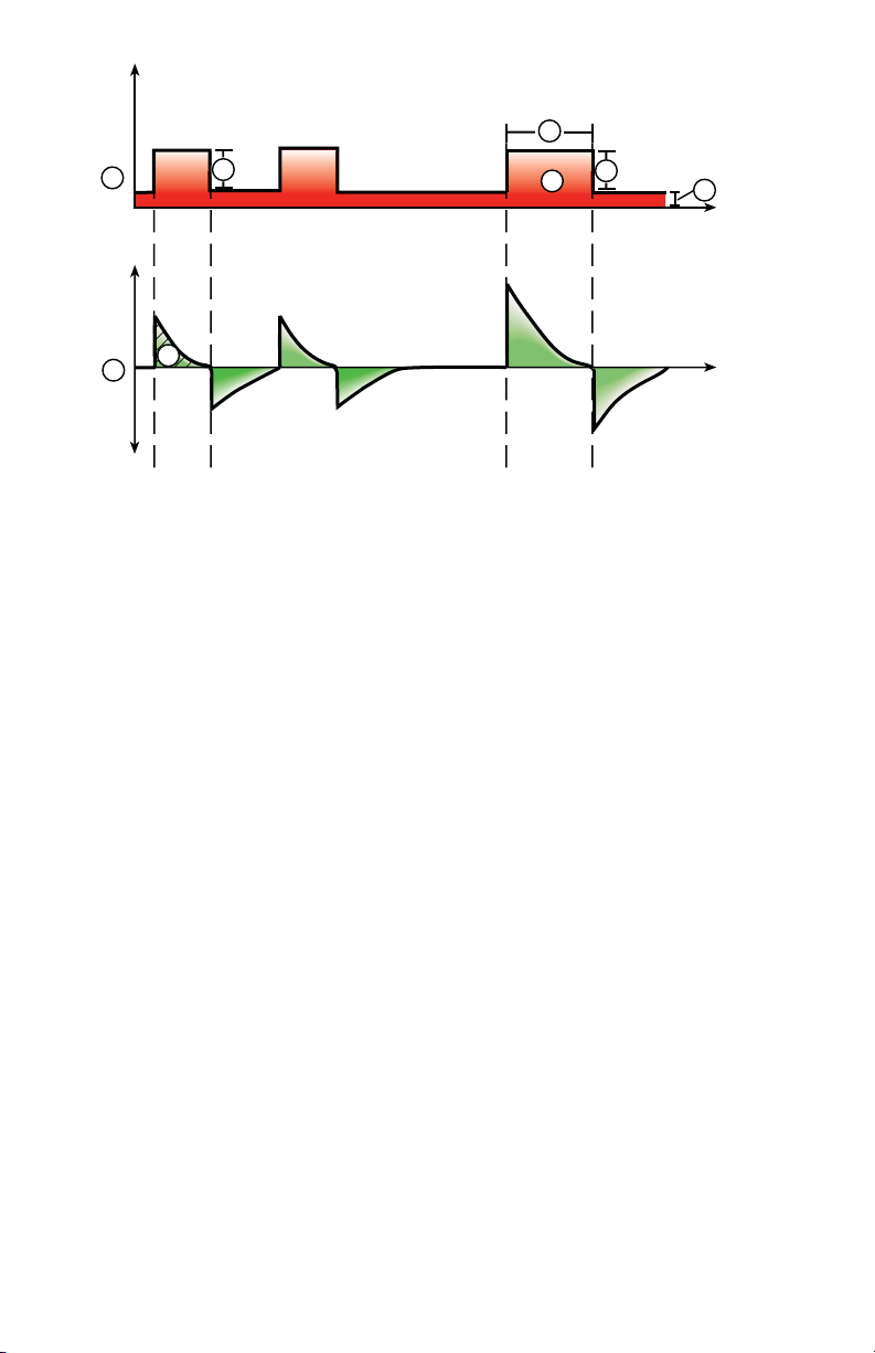
Figure 12 • NIV waveforms
1. Airway pressure (Paw) waveform
2. Pressure support (PS)
3. Inspiratory time (Backup Tinsp)
4. PEEP
5. Flow waveform
6. Backup Pinsp
7. Minimum rate backup breath
8. Tidal Volume (VT)
2
8
Spontaneous breathing trial (SBT mode)
6
7
4
AB.100.027
SBT mode is intended to be used to evaluate the patient’s ability to
breathe spontaneously during a specified duration of time. See "SBT
view" in the "Clinical decision support" section.
Prior to the SBT evaluation, the following setting limits must be entered:
• SBT Duration
• Apnea Time
• High and low MVexp alarm
• High and low RR alarm
During SBT mode, the patient initiates spontaneous breaths as the
ventilator maintains the set PEEP level and provides pressure support
(PS).
36
2065492-001
Page 39

Note
To set a pressure support level for spontaneous breaths, select Current
Mode > Mode Settings and enter a PS value.
Note
To evaluate the Spontaneous Breathing Trial, select Clinical Decision
Support > SBT.
Category Setting
Main Parameters FiO2
PEEP
PS
Patient Synchrony Insp Trigger
Exp Trigger
Bias Flow
PS Rise Time
Safety Pmax
Stop Criteria RR
MVexp
Apnea Time
1
4
2
5
Figure 13 • SBT waveforms
2065492-001
3
AB.100.202
37
Page 40

1. Airway pressure (Paw) waveform
2. Pressure support (PS)
3. PEEP
4. Flow waveform
5. Tidal Volume (VT)
38 2065492-001
Page 41

Operation
Operation
Power
Turning on power to the ventilator
1. Plug the power cord into an electrical outlet.
• The LED indicator illuminates (green) to indicate the main power
is connected.
2. Press the power switch on the back of the ventilator to the On
position.
• The start-up screen appears while the system runs a series of
automated self tests.
• When the self tests pass, the system goes into Standby and the
display shows the Standby menu.
• If the self tests fail, the display shows an alarm. See "List of
alarms" and "Troubleshooting" in the "Alarms and
troubleshooting" section or "List of alarms – Neonatal" in the
"Neonatal alarms and troubleshooting".
3. Listen for two distinctly different audio tones to sound to make sure
the primary speaker and backup buzzer are working properly.
4. Watch and verify the alarm light on the top of the display unit cycles
through the following colors: blue, red, and yellow.
WARNING
If both the primary and backup audio tones do not sound or the alarm
lights do not function correctly when the ventilator is powered on,
take the ventilator out of service. Contact an authorized service
representative to repair the system.
--
Turning off power to the ventilator
The ventilator may only be turned off when in Standby, Configuration
(Super User), or Service. If the ventilator is turned off during ventilation,
an alarm sounds and ventilation and monitoring continue. This ensures
the ventilator cannot be accidentally shut off during ventilation.
1. Disconnect the patient from the breathing circuit.
2. Select Standby.
Select Pause Ventilation to go to Standby. No ventilation will be
delivered. Select Cancel to continue ventilation if a warning message
is displayed.
3. Select Pause Ventilation.
• Monitoring and ventilation will stop.
2065492-001
39
Page 42

4. Press the power switch on the back of the ventilator to the Off
position.
Patient Setup
New Patient
Use these instructions for preparing the ventilator for a New Patient. After
powering on the ventilator the Standby menu displays.
1. Select NEW PATIENT.
2. Select Adult, Pediatric, or Neonatal patient type.
3. Select Patient ID (identification).
• Enter up to 10 characters and then select Confirm. (Only
English alpha-numeric characters may be entered).
WARNING
To protect patient privacy, do not use the patient’s name when
entering the patient ID (identification). Consider the facility’s
privacy policies when entering the patient ID.
--
4. Select Gender (male or female).
5. Select Height.
6. Select Weight.
• The ventilator calculates and displays the patient weight in
kilograms, the BSA (Body Surface Area), IBW (Ideal Body
Weight), and a suggested VT (Tidal Volume). See the "Clinical
theory" section for calculations.
• IBW is available for adult patients only.
7. Select (Endotrach, Trach, or ---).
When --- is selected, the ventilator will not compensate for tube
resistance.
8. Select Tube Diameter.
9. Verify and confirm settings.
Previous Patient
The Previous Patient button shows upon power up of the ventilator when
previous patient data exists. Previous Patient allows the clinician to use
the patient settings and alarm limits that were previously used and view
trends and historical data. For example, if a patient is extubated, but fails
to progress and needs to be re-intubated, the clinician may use the
previous patient settings.
40
2065492-001
Page 43

From the Standby menu, select PREVIOUS PATIENT.
Important
Previous Patient data is only saved when a normal shutdown sequence is
performed. Abrupt or unexpected power loss will prevent this data from
being saved.
Current Patient
Use this menu to update settings or change patient type from Pediatric to
Adult or Adult to Pediatric. If Neonatal is installed, patient types may be
changed from Neonatal to Pediatric or Pediatric to Neonatal.
1. Select Standby.
2. Select Current Patient.
The Current Patient menu shows.
3. Select the desired patient type and adjust settings.
2065492-001 41
Page 44

System Check
System Check overview
The ventilator should be fully cleaned and prepared for a patient before
performing the System Check.
When started, the System Check runs automatically. Selecting the
information icon will show the active progress in the System Check
Details menu. The steps will show a green check mark (pass) or a red X
(fail). When each check is completed, the next check begins.
A General Warning icon in the System Check indicates that a check has
not been performed or completed for the current patient. Both the yellow
warning icon and the yellow Start Ventilation button serves as a visual
warning that a System Check needs to be performed.
WARNING
To help ensure the proper function of the system, it is highly
recommended to complete the System Check between patients.
The patient must not be connected to the ventilator while completing the
System Check.
Complete the System Check with the breathing circuit and accessories
that will be used during ventilation.
If a System Check is not completed for the current patient, the system
uses the compliance and resistance data from the last completed system
check for the set patient type for all internal compensations. If the current
breathing circuit differs significantly from the previous circuit, differences
in ventilation parameters due to changes in the compensation process
are possible.
Failure to complete a System Check may result in inaccurate delivery and
monitoring. This may result in risk to the patient.
Additional System Check information
• The circuit leak is measured at 25 cmH2O. The resistance is the
measured resistance of the inspiratory limb of the patient circuit. If
the circuit leak is greater than 0.5 l/min or resistance or compliance
measurements cannot be calculated, the Circuit Check will fail.
• If the circuit leak is greater than 0.5 l/min or if the exhalation flow
sensor is changed after the System Check, the expiratory tidal
volume may have decreased accuracy.
• If the relief valve failure alarm activates after the System Check then
the ventilator will not allow ventilation until the relief valve portion of
the System Check has passed.
42
2065492-001
Page 45

Circuit Setup
Use the Circuit Setup menu to select settings that must be compensated
for in patient circuit measurements. The HME and Humidifier (must
include a heated expiratory limb) settings are selected in the Circuit
Setup. For adult and pediatric patient types the default selection is HME.
For the neonatal patient type, the Circuit Setup menu is not available and
the Humidifier selection will always be used.
WARNING
Changing the Circuit Setup will invalidate the current System Check
results. Changing the patient circuit after completion of System Check will
affect volume delivery and exhaled volume measurements. If any change
is made to Circuit Setup or the patient circuit, repeat the System Check.
Circuit Setup should be checked when setting up a New Patient or a
change has been made to the patient’s circuit setup.
A yellow warning icon will replace the previous System Check status icon
(pass or fail) when a change has been made in the Circuit Setup menu.
The yellow warning icon indicates that a System Check should be
performed.
1. Select Circuit Setup.
The Circuit Setup menu displays.
2. Select the check box for the HME or Humidifier.
Settings are confirmed when the setting is changed.
3. Select X to close the menu.
Running a System Check
1. From Standby, select SYSTEM CHECK.
The Run System Check menu shows.
2. Attach the breathing circuit and all accessories that will be used to
ventilate the patient.
• Complete the System Check using the appropriate flow sensor
per patient type. For example, use the neonatal flow sensor
when completing a System Check for a neonatal patient.
3. Occlude the patient wye using the occlusion port.
2065492-001
43
Page 46

INSP
EXP
1
AB.100.209
1. Occlusion port
4. Select Start.
The System Check starts and shows the results of each check.
The system runs the following checks:
• Paw transducer check
• Barometric pressure check
• Relief valve check
• Exhalation valve check
• Expiratory flow sensor check
• Air flow sensor check
• Oxygen sensor check
• O2 flow sensor check
• Resistance check
• Circuit measurements check (circuit leak, compliance, and
resistance)
Important
When performing the Resistance Check, the wye-piece and all
breathing accessories such as: D-lite (+)/Pedi-lite(+) sensor and
HME should remain on the occlusion port.
--
5. Select the information icon to see the System Check Details menu.
The System Check starts and shows the results of each check.
Note
Follow all on-screen system check instructions.
--
44
2065492-001
Page 47

As the System Check runs, the results of each check are displayed
as a green check mark (pass) or red X (fail). If a check fails, a Help
icon displays next to the failed check (red X). Select the Help icon to
view possible causes and help for troubleshooting a failure.
When the System Check is complete, the Final Result line will
display the patient type icon, a green check mark (pass) or red X
(fail), and the date and time of the System Check.
Patient ventilation
Setting the ventilator data source
The data source is used to obtain patient monitoring parameters from
either the ventilator or the airway module. See "Patient monitoring" for
detailed information. See "Setting the ventilator data source"in the
"Neonatal Operation" section.
1. Select Menu > System.
The System menu shows.
2. Select Data Source.
3. Select Ventilator or Airway Module to confirm settings.
If Ventilator is selected as the data source the Ventilator Data icon
displays in the lower right corner of the display; the internal sensors
of the ventilator will be the source for monitored data.
If Airway Module is selected as the data source and an airway
module is installed and warmed up, the Airway Module (Patient) data
icon displays in the lowerright corner of the display. The airway
module will be the first source for monitored data. If data is not
available through the airway module, monitored data will come from
the internal ventilator sensors.
Ventilator Data Source Icons
Ventilator data Airway Module (Patient) data
Note
When Airway Module is selected as the data source, the data source
icon will not be updated until the module is able to provide data. This
may take 2 to 5 minutes when a module is first installed into the
module bay. Only data available from the installed airway module will
be displayed on the ventilator, all other data will be from the
ventilator. For example, if a module capable of measuring CO2 and
2065492-001
45
Page 48

O2 only is installed, CO2 and O2 data displayed will be from the
module, all other data will be from the ventilator.
System menu
The System menu contains settings for data source selection, calibration
options, display brightness, and system information.
1. Select Menu > System.
The Airway Module type and software version number are shown
under data source.
2. Select Data Source (Ventilator or Airway Module).
• For Neonatal; select Ventilator or NFS. See "System menu" in
the "Neonatal Operation" section.
3. Select Calibrations (Airway Module, Paux Zero, or Purge Flow).
• Select Airway Module to calibrate the airway module.
• Select Paux Zero. A green check mark indicates Paux Zeroing
calibration was successful.
• Select Purge Flow. The Purge Flow check box may be checked
or unchecked when performing a Paux Zero. Continuous purge
flow will come from the Paux outlet when the Purge Flow check
box is selected. A white check mark indicates Purge Flow is
active.
Note
See "Purging the auxiliary pressure tubing" and "Zeroing
auxiliary pressure" in the "Setup and connections" section.
--
4. Select Display Brightness to adjust the brightness level of the user
interface.
Select brightness level of 1 (low) to 5 (high).
5. View system information: software version, service packet version,
running hours, altitude, O2 supply pressure, air supply pressure, and
battery status.
Setting a ventilation and backup mode
Ventilation modes are selected through the Current Mode button. The
selected ventilation mode shows with the corresponding mode settings.
Ventilation modes may be changed in Standby or during ventilation.
Ventilation mode settings should be set prior to connecting a patient to
the ventilator.
See "Backup mode" in the "Ventilation modes" section for additional
information.
46
2065492-001
Page 49

1. Select Current Mode.
2. Select the desired ventilation mode.
The title of the vent mode shows in the Mode Settings menu along
with the parameters for that mode. See "Ventilation modes" section
for detailed information on types of modes and settings.
Depending upon the facility default setup for ventilation modes, the
Mode Settings menu may contain two icons. The partial list icon
represents the facility’s set ventilation modes and the full list icon
represents the full set of ventilation modes available.
Select the appropriate icon to see available ventilation modes.
Partial list of ventilator modes Full list of ventilator modes
3. Select Assist Control, Leak Comp, or Trigger Comp if desired.
• Assist Control is only available in the following ventilation
modes: A/C VC, A/C PC, and A/C PRVC.
• See "Assist control", "Leak compensation", or "Trigger
compensation" in the "Ventilation modes" section for detailed
information.
4. Set the desired settings for the ventilation mode and confirm.
When ventilator settings are confirmed, the Mode Settings menu
closes and the selected ventilation mode shows in Current Mode.
5. To set a Backup Mode, select Current Mode.
6. Select Backup Settings.
• Set the desired settings for the backup mode and confirm.
7. Confirm all ventilation mode settings.
Setting limit indicators
When adjusting ventilation mode settings, yellow and red visual indicators
show when parameters are approaching their setting limits. Green visual
indicators show the parameters are appropriate for the setting limits.
Starting patient ventilation
WARNING
Ventilation will not start until 'Start Ventilation' is selected.
Ensure that the ventilator battery is fully charged before starting patient
ventilation. See "Battery status" for additional information.
2065492-001
47
Page 50

1. From Standby, select START VENTILATION.
If the Start Ventilation button is green, a System Check has been
completed for the current patient and when selected, will start
ventilation.
If the Start Ventilation button is yellow, the Complete System Check
warning alert will display the following:
Select Continue to bypass System Checkout and start ventilation.
Select Cancel to remain in Standby.
Note
It is recommended that System Check is completed prior to starting
ventilation.
--
2. After ventilation has started, connect the breathing circuit to the
patient.
Standby
Pausing ventilation
WARNING
The patient will not be ventilated when in Standby.
1. Disconnect the patient from the breathing circuit.
2. Select Standby.
Select Pause Ventilation to go to Standby. No ventilation will be
delivered. Select Cancel to continue ventilation if a warning message
is displayed.
3. Select Pause Ventilation.
• Monitoring and ventilation will stop.
Park Circuit
Park Circuit allows the patient circuit to be occluded without the ventilator
alarming while in Standby. When the patient circuit is positioned on the
occlusion port the display activates the PARK CIRCUIT selection.
WARNING
The patient will not be ventilated while the circuit is parked and in
Standby.
1. Disconnect the patient from the breathing circuit.
2. Select Standby.
Select Pause Ventialtion to go to Standby. No ventilation will be
delivered. Select Cancel to continue ventilation if a warning message
is displayed.
48
2065492-001
Page 51

3. Select Pause Ventilation.
• Monitoring and ventilation will stop.
4. Occlude the patient circuit using the occlusion port.
INSP
EXP
1. Occlusion port
5. Select PARK CIRCUIT.
• The display will show: Patient circuit is occluded and the
ventilator is in Standby.
Ventilation adjustments
1
AB.100.209
Ventilaltion modes and setting adjustments may be changed while in
Standby or while ventilating.
Changing ventilation modes
1. Select the Current Mode.
The Mode Settings menu shows.
2. Select the desired mode from the list.
• Use the scroll bar to view additional modes.
3. Confirm setting.
Setting Favorites
Up to four Favorite procedures may be selected to show on the upperright corner of the user interface.
1. Select Menu.
2. Select Procedures, Lung Mechanics, or Suction menus.
3. Select Assign Favorites.
2065492-001
49
Page 52

The Assign Favorites menu shows with a list of the following
procedures: Increase O2, Suction, Auto PEEP, Inspiratory Hold
Expiratory Hold, P 0.1, NIF, Vital Capacity, and Manual Breath.
4. Select up to four Favorites.
Favorites show in the upper right corner of the display.
Note
The following Favorite procedures begin automatically after they are
selected: Manual Breath, Suction, and Increase O2.
--
50 2065492-001
Page 53

Alarms and troubleshooting
Alarms and troubleshooting
Alarm priority
Audible and visual indicators tell the priority of the alarm.
Priority Color Light Tone
High Red Flashes red Series of five tones,
twice
Medium Yellow Flashes yellow Series of three tones
Low Blue Solid blue Single tone
Note
For medium and high priority alarms, the alarm tone is repeated until
audio pause is selected or the alarm condition is resolved. When high
priority alarms are not resolved within the set high alert audio time limit,
the pitch and volume of the tone increases to the maximum audio level.
See "Alarm setup" for information on how to set High Alert Audio.
When more than one alarm occurs at the same time, the alarm bar, alarm
light, and audible alarm tone indicates the highest priority alarm.
The color on the right side of the alarm light shows the priority of the
alarm. The left side of the alarm light is blue when audio pause is active.
Some medium priority and high priority alarms are de-escalated and
change to low priority alarm when audio pause is selected. To see which
alarms can be de-escalated, see "List of alarms - adult and pediatric" or
"List of alarms – Neonatal". Until the de-escalated alarm condition is
resolved, the low priority alarm stays active.
2065492-001
51
Page 54

Troubleshooting
The table lists possible problems that could occur when using the
ventilator. If a problem occurs that is not listed, see "Repair policy" in the
"Cleaning and maintenance" section for more information.
.
Symptom Problem Solution
The main power
indicator is not on.
Ventilator cannot be
turned off.
Backup audio alarm
turns on.
The electrical power
cord is not connected
correctly.
• Connect the power cord.
• Loosen the power cord
retaining clamp and
make sure plug is fully
seated. Then tighten the
retaining clamp.
The inlet circuit breaker
Turn the circuit breaker on.
(switch) is off.
The power cord is
Replace the power cord.
damaged.
The electrical outlet that
the power cord is
Use a different electrical
outlet.
connected to has no
power.
An internal fuse is open. Contact an authorized service
representative to repair the
ventilator.
The display unit cable is
loose.
Turn the ventilator switch off,
and then disconnect from the
main power. Check and
tighten the display unit
connectors.
The ventilator is not in
Standby.
A system failure has
occurred.
Set the ventilator to Standby,
and then turn the system off.
Contact an authorized service
representative to repair the
ventilator.
The display unit cable is
loose.
Turn the ventilator switch off,
and then disconnect from the
main power. Check and
tighten the display unit
connectors.
52 2065492-001
Page 55

Symptom Problem Solution
An alarm shows
although the data is
within range.
The alarm is from the
ventilator but the value
shown is from the
airway module. (Not
applicable for neonatal.)
The Ppeak high alarm
conditions are checked
before the display view
is updated.
• Calibrate the airway
module.
• Go to Menu > System
and change the selection
for Data Source.
No action required. In some
situations the ventilator will
react to a transient high
pressure before the data can
be sampled and shown on the
display.
Ventilator does not
deliver set VT in A/C VC
or SIMV VC modes.
The Plimit setting
prevents the full VT
from being delivered in
• Change the VT setting.
• Change the Plimit
setting.
the inspiratory period.
Ventilator does not
deliver set VT in A/C
PRVC, SIMV PRVC, or
BiLevel VG modes.
Ventilator transitions to
Backup mode.
Pmax alarm limit is
limiting delivered
inspiratory pressure.
The ventilator is at
minimum allowed
delivery.
MVexp low, Apnea
alarm, RR alarm, and
• Change the VT setting.
• Change the Pmax
setting.
• Change the VT setting.
• Change the Pmin
setting.
Change ventilation settings.
insufficient patient
ventilation.
Short delay in the
breath cycle at the
PEEP pressure level.
Automatic pressure
transducer zeroing
interference.
No action required. The
situation will be corrected
when zeroing is complete.
Automatic flow sensor
zeroing interference.
Ventilator is
automatically triggering
a breath.
The breathing circuit
leak rate is higher than
the flow trigger level.
• Enable Trigger
Compensation.
• Check the breathing
circuit for leaks.
• Turn Leak Comp On.
• Increase the Flow
triggering level or
change from Flow
triggering to Pressure
triggering.
• Make sure the correct
patient type is selected.
2065492-001 53
Page 56

Symptom Problem Solution
VT, compliance and
resistance values are
not accurate.
System Check was not
done with the current
patient circuit.
Flow sensors are dirty • Clean expiratory flow
Complete System Check with
the same breathing circuit
that will be used on the
patient.
sensor.
• Clean neonatal flow
sensor.
• Replace D-lite flow
sensor.
• Replace D-lite
spirometry sensing
lines.
• Calibrate gas module.
System Check fails. Water trap on the
exhalation valve is not
on tightly.
Patient circuit not
connected to the
ventilator.
Patient wye is not
occluded correctly.
Expiratory flow sensor
has failed.
Exhalation valve and
seals are not seated
correctly.
A connection port on the
patient circuit is open.
Leak in patient circuit is
very large.
System Check was
stopped before it
completed.
Touchscreen does not
respond.
The touchscreen is
locked.
The touchscreen
requires calibration or
repair.
Make sure the water trap is
tightly secured.
Attach the patient circuit to
the inspiratory and expiratory
ports.
Make sure the patient wye is
occluded completely with the
leak test plug.
Clean or replace the flow
sensor. Make sure flow
sensor is connected correctly.
Remove and replace the
exhalation valve.
Make sure all connection
ports are occluded.
Check the breathing circuit for
leaks.
Do a System Check and let it
complete.
Press the Lock hard key at
the bottom of the display unit.
Contact an authorized service
representative to repair the
ventilator.
54 2065492-001
Page 57

Cleaning and maintenance
Cleaning and maintenance
Note
Shared information section for adult, pediatric, and neonatal patient
types.
Part replacement schedule
The table shows recommended part replacement intervals. Replace the
part at the interval or number of cleaning cycles, whichever occurs first.
*Visually inspect parts to determine if cleaning or replacement is needed.
Look for deformation, cracks, or discoloration.
.
Interval Cleaning Cycles
Exhalation Valve Assembly 12 months 50
Exhalation Valve Diaphragm 12 months 50
Expiratory flow sensor 6 months 50
Neonatal flow sensor 6 months 25
Aerogen Aeroneb Pro Nebulizer and
T-adapters
Cart-mounted water trap *As needed 50
Water trap connector tubing (hytrel
tubing)
Display and ventilator fan filters *As needed *As needed
Compressor air inlet filter *As needed *As needed
D-lite sensor *As needed 50
Pedi-lite sensor *As needed 50
Inlet filter bowl *As needed *As needed
12 months 26
*As needed 50
Exhalation valve assembly
Obey infection control and safety procedures when handling water traps.
Infectious hazard might be present.
To remove the exhalation valve assembly:
1. Make sure the expiratory flow sensor has been removed, if not
remove the expiratory flow sensor from the exhalation valve
assembly.
2. Push down on the latch, as shown below, and then pull the
exhalation valve assembly away from the ventilator.
2065492-001
55
Page 58

Important
Do not try to remove the exhalation valve assembly without first
pushing down on the release latch. Damage might occur to the
housing.
--
AB.100.001
Figure 14 • Exhalation valve assembly
3. Remove the water trap and empty it. Make sure to save the o-ring
from the water trap.
2
1
AB.100.002
3
4
5
Figure 15 • Exhalation valve disassembly
1. Diaphragm
2. Seal
3. Exhalation valve housing (side view)
4. O-ring
5. Water trap
4. Lift the edge of the diaphragm to remove it from the exhalation valve
housing. Make sure to save the seal.
5. Before re-assembling or using the exhalation valve assembly, do the
following:
• Check for visible cracks, discoloration, or other degradation
• Replace any worn components
56
2065492-001
Page 59

• Perform System Check
Note
Re-assemble the exhalation flow sensor in reverse order.
--
User maintenance
Calibrate the system when any one of these occurs:
• Performance is questionable, such as a System Check failure.
• Internal components are serviced or replaced.
• Every six months.
For best performance of the system, calibrate more frequently.
Do the scheduled maintenance as shown in the table. Processing and
disassembly instructions are available later in this section.
Interval Maintenance
During cleaning and setup • Inspect the parts for damage and replace or
repair, as necessary.
As necessary • Empty the water trap on the exhalation
valve housing.
• Empty the water trap on the air pipeline inlet
fitting and replace the filter.
• Clean and replace the expiratory flow
sensor.
• Clean or replace the neonatal flow
sensor.
Monthly • Remove and clean fan filters for the display
unit, vent housing, airway module, and
compressor.
Every two months • Calibrate the airway module, if one is
installed.
Every six months • Calibrate the O2 Flow Control Valve*
• Calibrate the Air Flow Control Valve*
• Calibrate the Exhalation Valve*
• Check performance of internal battery. **
Annually • Schedule an annual service and
maintenance check for the ventilator, airway
module, and compressor.
2065492-001 57
Page 60

Important
*If the ventilator is moved from the facility, calibrate the O2 Flow Control
Valve, Air Flow Control Valve, and Exhalation Valve.
Important
**If the ventilator is used more than once a month on battery power, such
as to transport a patient within the facility, it is recommended that the
battery performance test be completed every six months.
58 2065492-001
Page 61

Neonatal Introduction
Neonatal Introduction
Overview of neonatal ventilation
The neonatal option on the CARESCAPE R860 provides ventilation for
neonatal patients weighing down to 0.25 kg. Using an optional neonatal
flow sensor at the patient wye, which connects to the ventilator with a
cable, allows for more accurate flow and volume monitoring in the
neonatal patient type.
WARNING
While ventilating in the neonatal patient type, additional patient
monitoring methods, such as SpO2, ECG, and CO2 are recommended.
Several features are available with the neonatal option:
• The calculated tidal volume per unit of weight is displayed while
adjusting the tidal volume setting.
• The volume delivered per unit of weight can be displayed during
ventilation for continuous monitoring.
• Safety-related limits have been imposed on ventilation settings and
alarm limits for the intended patient population.
Information presented in other sections of this manual applies to all
patient types, including neonatal. Exceptions are detailed in this section.
2065492-001
59
Page 62

Neonatal setup and connections
3
2
1
AB.100.175
Neonatal setup and connections
Note
See "Setup and connections" (shared information section for adult,
pediatric, and neonatal patient types) for additional information.
Connecting the Neonatal Flow Sensor (NFS)
WARNING
Calibrate the Neonatal Flow Sensor after every day of continuous use
and after replacement.
CAUTION
Port 1 must only be used to connect the neonatal flow sensor.
1. Connect the neonatal flow sensor cable connector to to port 1 on the
back of the ventilator.
2. Connect the neonatal flow sensor to the cable.
3. Connect the neonatal flow sensor to the patient breathing circuit.
4. Connect the neonatal flow sensor to the patient airway connection.
Note
To disconnect, follow the steps in reverse order.
--
60
2065492-001
Page 63

Neonatal ventilation modes
Neonatal ventilation modes
Ventilation mode basics
Invasive and non-invasive ventilation
The ventilator provides several standard modes for invasive ventilation
and non-invasive modes (nCPAP for neonates).
• Invasive ventilation modes provide a range of patient support, from
fully controlled mechanical breaths to pressure supported breaths for
spontaneously breathing patients.
• Non-invasive modes are intended to be used for spontaneously
breathing patients only.
Note
See ventilation mode descriptions for details about the settings and
features each mode provides.
The primary difference between setting up a patient for invasive and noninvasive ventilation is the accessories used.
• Invasive ventilation is delivered through an artificial airway (e.g.,
endotracheal tube), which is inserted into the patient's trachea.
• Non-invasive ventilation is delivered using positive-pressure
ventilation through an accessory such as a nasal mask or
mouthpiece. These accessories are often attached to the patient’s
head to increase the quality of the airway seal to minimize airway
leaks.
Non-invasive ventilation masks should be non-vented and must not
include an entrainment (inspiratory) valve. Patient circuits for use
with non-invasive ventilation must be dual-limb with connections for
both the inspiratory and expiratory ports of the ventilator.
Mechanical and spontaneous breaths
The ventilator offers multiple ventilation modes, which support
mechanical and spontaneous breaths.
Mechanical breaths are controlled by the ventilator. The ventilator uses
the selected mode settings to determine the characteristics of the breath
such as timing, volume, and pressure. Depending on which mode is set,
mechanical breaths are initiated by the ventilator or the patient.
• Ventilator-initiated: the ventilator uses the set respiratory rate to
initiate a breath.
• Patient-initiated: the patient activates the set inspiratory trigger (flow
or pressure) to initiate a breath.
2065492-001
61
Page 64

Spontaneous breaths are initiated and controlled by the patient.
AB.100.034
1
2
3
Note
In ventilation modes with a PS setting, spontaneous breaths are
pressure-supported at the PS level.
Figure 16 • Breath Types
1. Patient-initiated, mechanical breath
2. Spontaneous pressure supported breath
3. Ventilator-initiated, mechanical breath
Note
The segment colored orange in the waveform represents the breath
trigger.
Ventilation mode settings
Ventilation mode settings are separated into four categories:
• Main Parameters
• Breath Timing
• Patient Synchrony
• Safety
Each ventilation mode has a unique set of settings. See each ventilation
mode description for a list of applicable settings.
Quick Keys on the lower portion of the display provide access to
ventilation mode settings that are likely to be adjusted frequently. The
remaining settings can be adjusted in the Current Mode > Mode
Settings menu.
62
2065492-001
Page 65

Note
When changing ventilation modes, some settings may change if the two
modes do not share the same limits or increments.
• When the setting is greater than the maximum value allowed in the
new mode, the maximum value is set.
• When the setting is less than the minimum value of the new numeric
range, the minimum value is set.
• When the setting is between increments, the value is rounded to the
increment above or below it.
.
Main
Definition
Parameter
FiO2 Fraction of
inspired oxygen
PEEP Positive End
Expiratory
The percentage of oxygen that the ventilator
delivers to the patient.
The pressure that the ventilator holds in the
patient’s lungs during the expiratory phase.
Pressure
VT Tidal Volume The volume of gas that the ventilator delivers
with each volume-regulated or controlled
breath.
Pinsp Inspiratory
Pressure
The pressure above PEEP that is maintained
during the inspiratory phase of a pressureregulated breath. In BiLevel mode, Pinsp is the
pressure above PEEP at which the patient can
spontaneously breathe.
PS Pressure
Support
The pressure above PEEP that is maintained
during a pressure-supported breath.
Plow Low Pressure The low pressure level at which the patient can
spontaneously breathe in APRV mode. This
setting is equivalent to PEEP in other modes.
Phigh High Pressure The high pressure level at which the patient can
spontaneously breathe in APRV mode.
.
Breath
Definition
Timing
Rate Respiratory rate The number of breaths delivered to the patient
in one minute.
2065492-001 63
Page 66

Breath
Definition
Timing
Flow Inspiratory flow The rate at which the gas is delivered to the
patient during the inspiratory phase of a
volume-controlled breath.
I:E Inspiratory
The ratio of inspiratory time to expiratory time.
time:Expiratory
time
Tinsp Inspiratory Time The time in seconds that the ventilator uses to
deliver the inspiratory phase of the breath cycle.
Insp Pause Inspiratory
Pause
The percentage of the inspiratory phase during
which the breath is held and no additional flow
is delivered by the ventilator during volume
controlled breaths.
Tpause Pause Time The period in seconds at the end of the
inspiratory phase during which the breath is
held and no additional flow is delivered by the
ventilator during volume controlled breaths.
Thigh High Time The time in seconds that the ventilator holds the
high pressure level in APRV mode.
Tlow Low Time The time in seconds that the ventilator holds the
low pressure level in APRV mode.
.
Patient
Definition
Synchrony
Insp Trigger Inspiratory
Trigger
The patient effort required to initiate the
inspiratory phase of a breath. The trigger can be
set as either a positive flow value (Flow Trigger)
or a negative pressure deflection below PEEP
(Pressure Trigger).
Exp Trigger Expiratory
Trigger
The percentage of peak flow at which the
pressure supported breath inspiratory phase
ends and the expiratory phase begins.
Rise Time Rise Time The time in milliseconds for pressure to reach
90% of the set inspiratory pressure.
PS Rise Time Pressure
Support Rise
The time in milliseconds for pressure to reach
90% of the set pressure support level.
Time
64 2065492-001
Page 67

Patient
Definition
Synchrony
Bias Flow Bias Flow The continuous flow that is circulated through
the patient circuit during the expiratory phase of
the breath cycle. The bias flow may be
increased above this setting by the ventilator for
some FiO2 settings.
Tsupp Pressure
Support Time
.
The maximum inspiratory time for a pressuresupported breath.
Safety Definition
Pmax Maximum
Pressure
The maximum pressure allowed in the patient
breathing circuit. Once reached, the inspiratory
phase ends, and the ventilator immediately
begins the expiratory phase.
Plimit Pressure Limit The pressure at which the breath is limited and
held for the remaining inspiratory time in a
volume-controlled breath.
Pmin Minimum
Pressure
The minimum target pressure offset from PEEP
allowed in PRVC, VS, SIMV PRVC, and BiLevel
VG modes.
Minimum Rate Minimum
respiratory rate
The minimum number of breaths per minute a
patient must draw before the ventilator delivers
a backup breath.
Backup Pinsp Backup
Inspiratory
Pressure
Backup Tinsp Backup
Inspiratory Time
The pressure above PEEP that the ventilator
maintains as it delivers a mechanical breath in
CPAP/PS and NIV modes.
The time in seconds that the ventilator uses to
deliver the inspiratory phase for a mechanical
breath in VS, CPAP/PS and NIV modes.
Positive end expiratory pressure (PEEP)
PEEP is the low pressure maintained in the patient’s airway during the
expiratory phase. PEEP prevents the patient’s lungs from collapsing at
the end of expiration. Maintaining a PEEP level improves the possibility of
increasing oxygenation. PEEP (or the equivalent setting of Plow) is
available in all ventilation modes.
2065492-001
65
Page 68

Pressure support
Pressure support provides additional pressure during the inspiratory
phase of spontaneous breaths in spontaneous breathing modes. The PS
setting is available in the following ventilation modes:
• CPAP/PS
• SIMV VC
• SIMV PC
• SIMV PRVC
• BiLevel
• BiLevel VG
• NIV
• SBT
The maximum duration of the inspiratory phase for pressure-supported
breaths is Tsupp or 4 seconds for adults, 1.5 seconds for pediatrics, and
0.8 seconds for neonates. The inspiratory phase of pressure-supported
breaths ends when one of the following occurs:
• Set Exp Trigger is detected.
• Set VT is delivered (VS mode only).
• Pressure exceeds PEEP + PS + 2.5 cmH2O.
• Set Tsupp is reached.
Flow and pressure triggering
The ventilator detects a patient’s spontaneous breathing effort based on
changes in flow or pressure.
• Flow trigger: A breath is delivered when the patient’s inspiratory
effort reaches the Insp Trigger setting.
• Pressure trigger: A breath is delivered when the patient’s negative
airway pressure (below PEEP) reaches the Insp Trigger setting.
To set a flow or pressure trigger, adjust the Insp Trigger setting.
• To set a flow trigger, select Current Mode, select the trigger setting,
set a positive value using the Trim Knob and confirm.
• To set a pressure trigger, select Current Mode, select the trigger
setting, set a negative value using the Trim Knob and confirm.
The ventilator synchronizes mechanical breaths with patient triggers
when in the following modes:
• SIMV VC
• SIMV PC
• SIMV PRVC
• BiLevel
• BiLevel VG
66
2065492-001
Page 69

And when assist control is active in the following modes:
• A/C VC
• A/C PC
• A/C PRVC
Breath timing preferences
The parameters used to represent the timing of a delivered breath or
inspiratory phase of a delivered breath may be selected by the facility.
Note
Timing and Flow default settings may be changed by a Super User. See
the "Configuration menu (Super User)" section for more information.
The following table shows which settings are available based on the
ventilation mode and Timing and Flow selections.
Timing I:E I:E Tinsp Tinsp Tpause
Flow On Off On Off On
A/C VC I:E
Flow
A/C PC I:E I:E Tinsp Tinsp Tinsp
A/C PRVC I:E I:E Tinsp Tinsp Tinsp
SIMV VC Tinsp
Flow
SIMV PC Tinsp Tinsp Tinsp Tinsp Tinsp
SIMV PRVC Tinsp Tinsp Tinsp Tinsp Tinsp
BiLevel Tinsp Tinsp Tinsp Tinsp Tinsp
BiLevel VG Tinsp Tinsp Tinsp Tinsp Tinsp
APRV Thigh
Tlow
CPAP/PS Backup
Tinsp
VS Backup
Tinsp
NIV Backup
Tinsp
nCPAP Tinsp Tinsp Tinsp Tinsp Tinsp
I:E
Insp Pause
Tinsp
Insp Pause
Thigh
Tlow
Backup
Tinsp
Backup
Tinsp
Backup
Tinsp
Tinsp
Flow
Tinsp
Flow
Thigh
Tlow
Backup
Tinsp
Backup
Tinsp
Backup
Tinsp
Tinsp
Insp Pause
Tinsp
Insp Pause
Thigh
Tlow
Backup
Tinsp
Backup
Tinsp
Backup
Tinsp
Tpause
Flow
Tpause
Flow
Thigh
Tlow
Backup
Tinsp
Backup
Tinsp
Backup
Tinsp
2065492-001 67
Page 70

Note
Selecting a breath timing for the modes listed in the table will not affect
other ventilation modes.
Ventilation mode features
Tube compensation
When a patient is intubated, the endotracheal or tracheostomy tube
creates resistance in the airway. Tube compensation provides additional
pressure to compensate for the difference between the lung pressure and
breathing circuit pressure during the inspiratory phase of pressurecontrolled and pressure-supported breaths.
Tube compensation can be used to offset all or a percentage of the
additional resistive pressure created by the endotracheal tube.
Note
To set Tube compensation, a Tube Type and Tube Diameter must be set
in the New Patient or Current Patient menu.
WARNING
Tube compensation increases the pressure delivered to the patient. The
pressure delivered with tube compensation is limited to Pmax - 5 cmH2O.
Make sure that Pmax is set appropriately for the patient when using tube
compensation.
To set Tube Compensation, select Current Mode > Mode Settings and
select Tube Comp. A general message shows when tube compensation
is on.
Note
The options for tube compensation are: Endotrach, Trach, or ---. When --is selected, the ventilator will not compensate for tube resistance.
Assist control
Assist control allows the ventilator to synchronize mechanical breaths to
the patient's spontaneous efforts and the patient to trigger additional
mechanical breaths to the set respiratory rate in the following ventilation
modes:
• A/C VC
• A/C PC
• A/C PRVC
When the patient initiates a breath with assist control enabled, the
ventilator delivers a breath based on the mode settings. After a patientinitiated mechanical breath, the ventilator may delay the delivery of the
68
2065492-001
Page 71

next mechanical breath to prevent two mechanical breaths from being
delivered consecutively (breath stacking).
Note
Under certain conditions, such as high spontaneous breathing rates or
high leakage, the rate of mechanical breaths may not meet the set
respiratory rate.
A general message shows when assist control is off. When assist control
is off, the patient is able to draw spontaneous breaths at the set PEEP
level between mechanical breaths.
To set Assist Control, select Current Mode > Mode Settings and select
Assist Control (On or Off).
Leak compensation
WARNING
The exhaled volume of the patient can differ from the measured exhaled
volume due to leaks.
When the ventilator detects breathing circuit leaks, leak compensation
does two or three functions depending on the selected ventilation mode.
In all modes:
• Flow and volume waveforms and measured volume data are
adjusted to account for leaks.
In the following volume-controlled modes, the ventilator adjusts the tidal
volume delivered to compensate for leaks:
• A/C VC
• A/C PRVC
• SIMV VC
• SIMV PRVC
• BiLevel VG
• VS
The maximum tidal volume adjustment is limited to 100% of the set tidal
volume for the neonatal patient type.
• Neonatal - 100% of the set tidal volume
To set leak compensation, select Current Mode > Mode Settings and
select Leak Comp. A general message shows when leak compensation
is on.
Trigger compensation
Leaks can cause the ventilator to initiate breaths automatically (autotriggering). Trigger compensation adjusts the flow trigger to compensate
2065492-001
69
Page 72

for leaks, reducing the need to manually adjust the Insp Trigger setting to
prevent auto-triggering.
Trigger compensation is available in all ventilation modes. To set trigger
compensation, select Current Mode > Mode Settings, and select
Trigger Comp.
Backup mode
Backup mode is available if the ventilator detects insufficient ventilation in
modes that allow spontaneous breaths. When enabled, the ventilator
automatically enters the set Backup mode if either of the following occur:
• The Apnea alarm is activated.
• The patient’s expired minute volume (MVexp) is below 50% of the
set low MVexp alarm.
The set Backup mode is shown under the Backup mode check box in
Current Mode > Mode Settings . To enable Backup mode, select the
check box.
Backup settings are a subset of available settings in each ventilation
mode. Adjust Backup settings in Current Mode > Mode Settings >
Backup Settings.
Note
Settings that are not designated as Backup settings remain at the current
value when the ventilator transitions to the set Backup mode.
WARNING
Ensure that all users at the facility have been trained and notified of the
facility default Backup mode settings. Before deactivating backup
ventilation for a specific mode, ensure that all users at the facility have
been trained and notified of these settings.
Backup mode is available in the following ventilation modes:
• SIMV VC
• SIMV PC
• SIMV PRVC
• BiLevel
• BiLevel VG
• CPAP/PS
• VS
• APRV
The following ventilation modes may be set as the Backup mode:
• A/C VC
• A/C PC
70
2065492-001
Page 73

• A/C PRVC
• SIMV VC
• SIMV PC
• SIMV PRVC
• BiLevel
• BiLevel VG
Nasal continuous positive airway pressure (nCPAP)
The nCPAP mode is a purchasable option. The nCPAP mode is intended
for non-invasive ventilation of neonatal patients only.
WARNING
Before using nCPAP mode, the patient should demonstrate all of the
following characteristics:
• Is responsive
• Breathes spontaneously
• Has a controlled airway
• Requires pressure support ventilation
• Patient needs oxygen therapy
While in nCPAP ventilation, the ventilator is to be provided with CO2
monitoring equipment that complies with ISO 80601-2-55 or ISO 21647.
If the Apnea Time, Leak Limit, or MVexp low alarms are disabled,
additional monitoring, such as SpO2, ECG, and CO2, is recommended to
prevent the patient from hypoventilating while ventilating in the neonatal
patient type without the neonatal flow sensor.
The Patient Disconnected alarm is not enabled during nCPAP mode. The
Apnea, Circuit Leak, MVexp low, and PEEPe low alarms are the primary
disconnection notifications. To make sure that the ventilator detects a
patient disconnect, set the PEEPe Low limit correctly for the patient’s
condition.
Note
The neonatal flow sensor is not used during nCPAP.
The nCPAP mode allows a clinician to set a FiO2 and Bias Flow rate for
gas through the patient circuit. The clinician can also set a level of PEEP
2065492-001
71
Page 74

to be maintained in the patient circuit and a respiratory rate for
mechanical breaths. The mechanical breaths delivered are time cycled,
but are synchronised with a patient trigger where necessary. The clinician
will set the inspiratory pressure inspiratory time for the time cycled
breaths.
The Bias Flow rate, set by the clinician will be used to maintain PEEP
and for the inspiratory phase of the time cycled mechanical breaths.
Insufficient setting of the Bias Flow rate may cause an inability to reach or
maintain the set PEEP and or inspiratory pressure during the mechanical
breaths.
During nCPAP, the patient draws spontaneous breaths through a nasal
interface as the ventilator maintains the set inspiratory pressure.
If large patient circuit leaks are present, the user may disable the MVexp
low, Apnea Time, and Leak Limit alarms.
Important
Backup ventilation is not available while using nCPAP mode.
The following settings are available in nCPAP mode:
Category Setting
Main Parameters FiO2
PEEP
Pinsp
Breath Timing Rate
Tinsp
Patient Synchrony Bias Flow
Insp Trigger
Safety Pmax
72 2065492-001
Page 75

AB.100.205
1
4
6
5
2
3
Figure 17 • nCPAP waveform
1. Airway pressure (Paw) waveform
2. Tinsp
3. Pinsp
4. PEEP
5. Expiratory time
6. Flow waveform
Invasive neonatal ventilation modes
The following invasive ventilation modes are availble for neonatal
patients. See "Ventilation modes" for detailed information.
• A/C VC
• A/C PC
• A/C PRVC
• SIMV VC
• SIMV PC
• CPAP/PS
• BiLevel
• SIMV PRVC
• BiLevel VG
• APRV
• VS
• SBT
2065492-001
73
Page 76

Note
BiLevel, SIMV PRVC, BiLevel VG, APRV, and VS are purchasable
options.
74 2065492-001
Page 77

Neonatal Operation
Neonatal Operation
Power
Turning on power to the ventilator
1. Plug the power cord into an electrical outlet.
• The LED indicator illuminates (green) to indicate the main power
is connected.
2. Press the power switch on the back of the ventilator to the On
position.
• The start-up screen appears while the system runs a series of
automated self tests.
• When the self tests pass, the system goes into Standby and the
display shows the Standby menu.
• If the self tests fail, the display shows an alarm. See "List of
alarms" and "Troubleshooting" in the "Alarms and
troubleshooting" section or "List of alarms – Neonatal" in the
"Neonatal alarms and troubleshooting".
3. Listen for two distinctly different audio tones to sound to make sure
the primary speaker and backup buzzer are working properly.
4. Watch and verify the alarm light on the top of the display unit cycles
through the following colors: blue, red, and yellow.
WARNING
If both the primary and backup audio tones do not sound or the alarm
lights do not function correctly when the ventilator is powered on,
take the ventilator out of service. Contact an authorized service
representative to repair the system.
--
Turning off power to the ventilator
The ventilator may only be turned off when in Standby, Configuration
(Super User), or Service. If the ventilator is turned off during ventilation,
an alarm sounds and ventilation and monitoring continue. This ensures
the ventilator cannot be accidentally shut off during ventilation.
1. Disconnect the patient from the breathing circuit.
2. Select Standby.
Select Pause Ventilation to go to Standby. No ventilation will be
delivered. Select Cancel to continue ventilation if a warning message
is displayed.
3. Select Pause Ventilation.
• Monitoring and ventilation will stop.
2065492-001
75
Page 78

4. Press the power switch on the back of the ventilator to the Off
position.
Patient Setup
New Patient
Use these instructions for preparing the ventilator for a New Patient. After
powering on the ventilator the Standby menu displays.
1. Select NEW PATIENT.
2. Select Adult, Pediatric, or Neonatal patient type.
3. Select Patient ID (identification).
• Enter up to 10 characters and then select Confirm. (Only
English alpha-numeric characters may be entered).
WARNING
To protect patient privacy, do not use the patient’s name when
entering the patient ID (identification). Consider the facility’s
privacy policies when entering the patient ID.
--
4. Select Gender (male or female).
5. Select Height.
6. Select Weight.
• The ventilator calculates and displays the patient weight in
kilograms, the BSA (Body Surface Area), IBW (Ideal Body
Weight), and a suggested VT (Tidal Volume). See the "Clinical
theory" section for calculations.
• IBW is available for adult patients only.
7. Select (Endotrach, Trach, or ---).
When --- is selected, the ventilator will not compensate for tube
resistance.
8. Select Tube Diameter.
9. Verify and confirm settings.
Previous Patient
The Previous Patient button shows upon power up of the ventilator when
previous patient data exists. Previous Patient allows the clinician to use
the patient settings and alarm limits that were previously used and view
trends and historical data. For example, if a patient is extubated, but fails
to progress and needs to be re-intubated, the clinician may use the
previous patient settings.
76
2065492-001
Page 79

From the Standby menu, select PREVIOUS PATIENT.
Important
Previous Patient data is only saved when a normal shutdown sequence is
performed. Abrupt or unexpected power loss will prevent this data from
being saved.
Current Patient
Use this menu to update settings or change patient type from Pediatric to
Adult or Adult to Pediatric. If Neonatal is installed, patient types may be
changed from Neonatal to Pediatric or Pediatric to Neonatal.
1. Select Standby.
2. Select Current Patient.
The Current Patient menu shows.
3. Select the desired patient type and adjust settings.
2065492-001 77
Page 80

System Check
System Check overview - neonatal
The ventilator should be fully cleaned and prepared for a patient before
performing the System Check.
When started, the System Check runs automatically. Selecting the
information icon will show the active progress in the System Check
Details menu. The steps will show a green check mark (pass) or a red X
(fail). When each check is completed, the next check begins.
A General Warning icon in the System Check indicates that a check has
not been performed or completed for the current patient. Both the yellow
warning icon and the yellow Start Ventilation button serves as a visual
warning that a System Check needs to be performed.
WARNING
To help ensure the proper function of the system, it is highly
recommended to complete the System Check between patients.
The patient must not be connected to the ventilator while completing the
System Check.
Changing the patient circuit after completion of System Check will affect
volume delivery and exhaled volume measurements. If any change is
made to the patient circuit, repeat the System Check.
Complete the System Check with the breathing circuit and accessories
that will be used during ventilation.
If a System Check is not completed for the current patient, the system
uses the compliance and resistance data from the last completed system
check for the set patient type for all internal compensations. If the current
breathing circuit differs significantly from the previous circuit, differences
in ventilation parameters due to changes in the compensation process
are possible.
Failure to complete a System Check may result in inaccurate delivery and
monitoring. This may result in risk to the patient.
Running a neonatal system check
1. From Standby, select SYSTEM CHECK.
The Run System Check menu shows.
2. Attach the neonatal flow sensor to the breathing circuit and all
accessories that will be used to ventilate the patient.
3. Occlude the patient wye using the occlusion port.
78
2065492-001
Page 81

INSP
EXP
1
AB.100.208
1. Occlusion port
4. Select Start.
The System Check starts and shows the results of each check.
The system runs the following checks:
• Paw transducer check
• Barometric pressure check
• Relief valve check
• Exhalation valve check
• Expiratory flow sensor check
• Air flow sensor check
• Oxygen sensor check
• O2 flow sensor check
• Neonatal flow sensor check
• Resistance check
• Circuit measurements check (circuit leak, compliance, and
resistance)
Important
When performing the Neonatal Flow Sensor Check, remove the
occlusion from the neonatal flow sensor, keeping the flow sensor
attached to the patient circuit.
--
5. Select the information icon to see the System Check Details menu.
The System Check starts and shows the results of each check.
Note
Follow all on-screen system check instructions.
--
2065492-001
79
Page 82

As the System Check runs, the results of each check are displayed
as a green check mark (pass) or red X (fail). If a check fails, a Help
icon displays next to the failed check (red X). Select the Help icon to
view possible causes and help for troubleshooting a failure.
When the System Check is complete, the Final Result line will
display the patient type icon, a green check mark (pass) or red X
(fail), and the date and time of the System Check.
Patient ventilation
System menu (neonatal)
The System menu contains settings for data source selection, NFS
calibration options, display brightness and system information.
WARNING
Calibrate the Neonatal Flow Sensor after every day of continuous use.
1. Select Menu > System.
2. Select Data Source (Ventilator or NFS).
3. Select Calibrations (NFS, Paux Zero, or Purge Flow) .
• Select NFS to calibrate the Neonatal Flow Sensor. A green
check mark indicates the NFS calibration was successful.
• Select Paux Zero. A green check mark indicates Paux Zeroing
calibration was successful.
• Select Purge Flow. The Purge Flow check box may be checked
or unchecked when performing a Paux Zero. Continuous purge
flow will come from the Paux outlet when the Purge Flow check
box is selected. A white check mark indicates Purge Flow is
active.
Note
See "Purging the auxiliary pressure tubing" and "Zeroing
auxiliary pressure" in the "Setup and connections" section.
--
4. Select Display Brightness to adjust the brightness level of the user
interface.
Select brightness level of 1 (low) to 5 (high).
5. View system information: Software version, Service Pack version,
Running hours, Altitude, O2 pressure, Air pressure, and Battery
status.
80
2065492-001
Page 83

Setting the ventilator data source
The data source is used to obtain patient monitoring parameters from
either the ventilator or the Neonatal Flow Sensor (NFS). See "Neonatal
patient monitoring" for detailed information.
WARNING
Calibrate the Neonatal Flow Sensor after every day of continuous use.
While ventilating in the neonatal patient type without the neonatal flow
sensor, additional patient monitoring such as SpO2, ECG, and CO2 are
recommended.
Flow and volume accuracy are decreased when not using the neonatal
flow sensor for the neonatal patient type.
1. Select Menu >System.
The System menu shows.
2. Select Ventilator or NFS and confirm settings.
If the ventilator is selected as the data source the Ventilator Data
icon displays, the internal flow sensors of the ventilator will be used
for flow and volume monitoring.
If the NFS is selected as the data source the Patient Data icon
displays, the neonatal flow sensor will be used for flow and volume
monitoring.
Ventilator Data Source Icons
Ventilator Data NFS (Patient) Data
Setting a ventilation and backup mode
Ventilation modes are selected through the Current Mode button. The
selected ventilation mode shows with the corresponding mode settings.
Ventilation modes may be changed in Standby or during ventilation.
Ventilation mode settings should be set prior to connecting a patient to
the ventilator.
See "Backup mode" in the "Ventilation modes" section for additional
information.
1. Select Current Mode.
2. Select the desired ventilation mode.
2065492-001
81
Page 84

The title of the vent mode shows in the Mode Settings menu along
with the parameters for that mode. See "Ventilation modes" section
for detailed information on types of modes and settings.
Depending upon the facility default setup for ventilation modes, the
Mode Settings menu may contain two icons. The partial list icon
represents the facility’s set ventilation modes and the full list icon
represents the full set of ventilation modes available.
Select the appropriate icon to see available ventilation modes.
Partial list of ventilator modes Full list of ventilator modes
3. Select Assist Control, Leak Comp, or Trigger Comp if desired.
• Assist Control is only available in the following ventilation
modes: A/C VC, A/C PC, and A/C PRVC.
• See "Assist control", "Leak compensation", or "Trigger
compensation" in the "Ventilation modes" section for detailed
information.
4. Set the desired settings for the ventilation mode and confirm.
When ventilator settings are confirmed, the Mode Settings menu
closes and the selected ventilation mode shows in Current Mode.
5. To set a Backup Mode, select Current Mode.
6. Select Backup Settings.
• Set the desired settings for the backup mode and confirm.
7. Confirm all ventilation mode settings.
Setting limit indicators
When adjusting ventilation mode settings, yellow and red visual indicators
show when parameters are approaching their setting limits. Green visual
indicators show the parameters are appropriate for the setting limits.
Starting patient ventilation
WARNING
Ventilation will not start until 'Start Ventilation' is selected.
Ensure that the ventilator battery is fully charged before starting patient
ventilation. See "Battery status" for additional information.
1. From Standby, select START VENTILATION.
82
2065492-001
Page 85

If the Start Ventilation button is green, a System Check has been
completed for the current patient and when selected, will start
ventilation.
If the Start Ventilation button is yellow, the Complete System Check
warning alert will display the following:
Select Continue to bypass System Checkout and start ventilation.
Select Cancel to remain in Standby.
Note
It is recommended that System Check is completed prior to starting
ventilation.
--
2. After ventilation has started, connect the breathing circuit to the
patient.
Standby
Pausing ventilation
WARNING
The patient will not be ventilated when in Standby.
1. Disconnect the patient from the breathing circuit.
2. Select Standby.
Select Pause Ventilation to go to Standby. No ventilation will be
delivered. Select Cancel to continue ventilation if a warning message
is displayed.
3. Select Pause Ventilation.
• Monitoring and ventilation will stop.
Park Circuit
Park Circuit allows the patient circuit to be occluded without the ventilator
alarming while in Standby. When the patient circuit is positioned on the
occlusion port the display activates the PARK CIRCUIT selection.
WARNING
The patient will not be ventilated while the circuit is parked and in
Standby.
1. Disconnect the patient from the breathing circuit.
2. Select Standby.
Select Pause Ventialtion to go to Standby. No ventilation will be
delivered. Select Cancel to continue ventilation if a warning message
is displayed.
3. Select Pause Ventilation.
• Monitoring and ventilation will stop.
2065492-001
83
Page 86

4. Occlude the patient circuit using the occlusion port.
INSP
EXP
1
AB.100.209
1. Occlusion port
5. Select PARK CIRCUIT.
• The display will show: Patient circuit is occluded and the
ventilator is in Standby.
Ventilation adjustments
Ventilaltion modes and setting adjustments may be changed while in
Standby or while ventilating.
Changing ventilation modes
1. Select the Current Mode.
The Mode Settings menu shows.
2. Select the desired mode from the list.
• Use the scroll bar to view additional modes.
3. Confirm setting.
Setting Favorites
Up to four Favorite procedures may be selected to show on the upperright corner of the user interface.
1. Select Menu.
2. Select Procedures, Lung Mechanics, or Suction menus.
3. Select Assign Favorites.
84
2065492-001
Page 87

The Assign Favorites menu shows with a list of the following
procedures: Increase O2, Suction, Auto PEEP, Inspiratory Hold
Expiratory Hold, P 0.1, NIF, Vital Capacity, and Manual Breath.
4. Select up to four Favorites.
Favorites show in the upper right corner of the display.
Note
The following Favorite procedures begin automatically after they are
selected: Manual Breath, Suction, and Increase O2.
--
2065492-001 85
Page 88

Neonatal alarms and troubleshooting
Neonatal alarms and troubleshooting
Alarm priority
Audible and visual indicators tell the priority of the alarm.
Priority Color Light Tone
High Red Flashes red Series of five tones,
twice
Medium Yellow Flashes yellow Series of three tones
Low Blue Solid blue Single tone
Note
For medium and high priority alarms, the alarm tone is repeated until
audio pause is selected or the alarm condition is resolved. When high
priority alarms are not resolved within the set high alert audio time limit,
the pitch and volume of the tone increases to the maximum audio level.
See "Alarm setup" for information on how to set High Alert Audio.
When more than one alarm occurs at the same time, the alarm bar, alarm
light, and audible alarm tone indicates the highest priority alarm.
The color on the right side of the alarm light shows the priority of the
alarm. The left side of the alarm light is blue when audio pause is active.
Some medium priority and high priority alarms are de-escalated and
change to low priority alarm when audio pause is selected. To see which
alarms can be de-escalated, see "List of alarms - adult and pediatric" or
"List of alarms – Neonatal". Until the de-escalated alarm condition is
resolved, the low priority alarm stays active.
86
2065492-001
Page 89

Troubleshooting
The table lists possible problems that could occur when using the
ventilator. If a problem occurs that is not listed, see "Repair policy" in the
"Cleaning and maintenance" section for more information.
.
Symptom Problem Solution
The main power
indicator is not on.
Ventilator cannot be
turned off.
Backup audio alarm
turns on.
The electrical power
cord is not connected
correctly.
• Connect the power cord.
• Loosen the power cord
retaining clamp and
make sure plug is fully
seated. Then tighten the
retaining clamp.
The inlet circuit breaker
Turn the circuit breaker on.
(switch) is off.
The power cord is
Replace the power cord.
damaged.
The electrical outlet that
the power cord is
Use a different electrical
outlet.
connected to has no
power.
An internal fuse is open. Contact an authorized service
representative to repair the
ventilator.
The display unit cable is
loose.
Turn the ventilator switch off,
and then disconnect from the
main power. Check and
tighten the display unit
connectors.
The ventilator is not in
Standby.
A system failure has
occurred.
Set the ventilator to Standby,
and then turn the system off.
Contact an authorized service
representative to repair the
ventilator.
The display unit cable is
loose.
Turn the ventilator switch off,
and then disconnect from the
main power. Check and
tighten the display unit
connectors.
2065492-001 87
Page 90

Symptom Problem Solution
An alarm shows
although the data is
within range.
The alarm is from the
ventilator but the value
shown is from the
airway module. (Not
applicable for neonatal.)
The Ppeak high alarm
conditions are checked
before the display view
is updated.
• Calibrate the airway
module.
• Go to Menu > System
and change the selection
for Data Source.
No action required. In some
situations the ventilator will
react to a transient high
pressure before the data can
be sampled and shown on the
display.
Ventilator does not
deliver set VT in A/C VC
or SIMV VC modes.
The Plimit setting
prevents the full VT
from being delivered in
• Change the VT setting.
• Change the Plimit
setting.
the inspiratory period.
Ventilator does not
deliver set VT in A/C
PRVC, SIMV PRVC, or
BiLevel VG modes.
Ventilator transitions to
Backup mode.
Pmax alarm limit is
limiting delivered
inspiratory pressure.
The ventilator is at
minimum allowed
delivery.
MVexp low, Apnea
alarm, RR alarm, and
• Change the VT setting.
• Change the Pmax
setting.
• Change the VT setting.
• Change the Pmin
setting.
Change ventilation settings.
insufficient patient
ventilation.
Short delay in the
breath cycle at the
PEEP pressure level.
Automatic pressure
transducer zeroing
interference.
No action required. The
situation will be corrected
when zeroing is complete.
Automatic flow sensor
zeroing interference.
Ventilator is
automatically triggering
a breath.
The breathing circuit
leak rate is higher than
the flow trigger level.
• Enable Trigger
Compensation.
• Check the breathing
circuit for leaks.
• Turn Leak Comp On.
• Increase the Flow
triggering level or
change from Flow
triggering to Pressure
triggering.
• Make sure the correct
patient type is selected.
88 2065492-001
Page 91

Symptom Problem Solution
VT, compliance and
resistance values are
not accurate.
System Check was not
done with the current
patient circuit.
Flow sensors are dirty • Clean expiratory flow
Complete System Check with
the same breathing circuit
that will be used on the
patient.
sensor.
• Clean neonatal flow
sensor.
• Replace D-lite flow
sensor.
• Replace D-lite
spirometry sensing
lines.
• Calibrate gas module.
System Check fails. Water trap on the
exhalation valve is not
on tightly.
Patient circuit not
connected to the
ventilator.
Patient wye is not
occluded correctly.
Expiratory flow sensor
has failed.
Exhalation valve and
seals are not seated
correctly.
A connection port on the
patient circuit is open.
Leak in patient circuit is
very large.
System Check was
stopped before it
completed.
Touchscreen does not
respond.
The touchscreen is
locked.
The touchscreen
requires calibration or
repair.
Make sure the water trap is
tightly secured.
Attach the patient circuit to
the inspiratory and expiratory
ports.
Make sure the patient wye is
occluded completely with the
leak test plug.
Clean or replace the flow
sensor. Make sure flow
sensor is connected correctly.
Remove and replace the
exhalation valve.
Make sure all connection
ports are occluded.
Check the breathing circuit for
leaks.
Do a System Check and let it
complete.
Press the Lock hard key at
the bottom of the display unit.
Contact an authorized service
representative to repair the
ventilator.
2065492-001 89
Page 92

nCPAP Troubleshooting
.
Symptom Problem Solution
Auto-triggering. Trigger setting is too
sensitive.
No triggering or
missed triggers.
Trigger setting is not
sensitive enough.
• Increase the Insp Trigger
setting.
• Set a pressure Insp
Trigger.
• Enable trigger
compensation.
• Check the patient
interface.
• Check the expiratory flow
sensor.
• Decrease the flow Insp
Trigger setting.
• Increase the pressure Insp
Trigger setting.
90 2065492-001
Page 93

Neonatal cleaning and maintenance
Neonatal cleaning and maintenance
Note
See "Cleaning and maintenance" (shared information section for adult,
pediatric, and neonatal patient types) for additional information.
Processing the neonatal flow sensor
WARNING
Calibrate the Neonatal Flow Sensor after every day of continuous use.
CAUTION
Do not use compressed air or a water jet to clean the neonatal flow
sensor.
Do not use an automated washer to clean or disinfect flow sensors.
Do not insert anything into the flow sensor to clean internal surfaces.
Damage may occur to the flow sensor.
Note
See the shared "Cleaning and maintenance" section for detailed cleaning
instructions.
Calibrating the neonatal flow sensor
The neonatal flow sensor can be calibrated automatically through the
System Check or manually through the System menu.
WARNING
Calibrate the Neonatal Flow Sensor (NFS) after every day of continuous
use.
Note
The neonatal flow sensor can only be manually calibrated when the
neonatal flow sensor is not set as the data source.
1. Select Menu > System.
2. Under Data Source, select Ventilator.
3. Hold the flow sensor between thumb and index finger to occlude both
ports at the same time.
2065492-001
91
Page 94

AB.100.183
4. Under Calibration, select NFS.
When the calibration is complete, a green check mark (pass) or red
X (fail) will appear next to NFS.
5. Under Data Source, select NFS.
6. Connect the flow sensor to the patient circuit.
92 2065492-001
Page 95

CARESCAPE R860
Quick Reference Guide
English
2065492-001
03 15 D
 Loading...