

Page 1

OSMONICS
TONKAFLOPUMPS
QSV SERIES
INSTALLATION,
OPERATION, AND
MAINTENANCE MANUAL
For QS1800V and QS2800V Series
Tonkaflo Centrifugal Pumps with
Quiet, Stainless Steel Vertically
Mounted, Flow-Cooled Motors
GE Infrastructure
Water & Process Technologies
Page 2

Page 3

OPERATION AND MAINTENANCE MANUAL
FOR SERIES QS1800V AND QS2800V SERIES
TONKAFLO
®
PUMPS
T
ABLE OF CONTENTS
Page
1.0 INTRODUCTION.....................................................................................................................................1
2.0 TONKAFLO SPECIFICATION..............................................................................................................2
2.1 Pump Label Nomenclature .............................................................................................2
2.2 Performance Specifications............................................................................................3
2.3 Material Specifications......................................................................................................4
3.0 PUMP INSTALLATION..........................................................................................................................5
3.1 Inspection ................................................................................................................................5
3.2 Pump Mounting and Location .......................................................................................5
3.3 Operation Safeguards........................................................................................................6
3.4 Inlet and Discharge.............................................................................................................6
3.4.1 Inlet Piping................................................................................................................6
3.4.2 Discharge Piping....................................................................................................7
3.4.3 Piping Connections...............................................................................................7
3.4.4 Inlet Line Screen/Filter ........................................................................................7
3.4.5 Discharge Screen (Strainer)..............................................................................8
3.5 Pump Priming ........................................................................................................................9
3.6 Motor Wiring........................................................................................................................10
3.6.1 Single-Phase Motors.........................................................................................10
3.6.2 Three-Phase Motors..........................................................................................11
3.6.3 Three-Phase Power Imbalance ...................................................................12
3.6.4 Wire Sizing .............................................................................................................12
3.7 Electrical Grounding.........................................................................................................13
3.8 Motor Protection................................................................................................................13
4.0 PUMP OPERATION.............................................................................................................................14
4.1 Priming ...................................................................................................................................14
4.2 Operation ..............................................................................................................................14
4.3 Restarts ..................................................................................................................................14
5.0 GENERAL TROUBLESHOOTING...................................................................................................15
Page 4

Page
6.0 FIELD MAINTENANCE......................................................................................................................20
6.1 Flow-Cooled Motor and Liquid End - Tonkaflo Service Policy .....................20
6.2 Liquid End Removal and Installation........................................................................20
7.0 TONKAFLO RETURN GOODS AUTHORIZATION (RGA) PROCEDURE.............................23
7.1 Motor Warranty..................................................................................................................23
7.2 In-Warranty Pump Failures ..........................................................................................23
7.3 Out-of-Warranty Pump Failures.................................................................................23
7.4 Shipping Charges...............................................................................................................23
7.4.1 In-Warranty ..........................................................................................................23
7.4.2 Out-of-Warranty.................................................................................................23
8.0 DIMENSIONAL DRAWING ..............................................................................................................24
9.0 REPLACEMENT PARTS......................................................................................................................25
9.1 Parts Schematic.................................................................................................................25
9.2 Parts List, Standard Models.........................................................................................26
9.3 Accessories and QS Series Tonkaflo Pumps.........................................................26
9.4 Ordering Parts.....................................................................................................................27
10.0 WARRANTY...........................................................................................................................................28
Page 5

Page
LIST OF FIGURES
Figure Description
2.1 Pump and Motor Labels.....................................................................................2
3.2 Right Angle Inlet and Vertical Position........................................................5
3.3 Discharge Screen Installation .........................................................................8
3.4 Priming Water Level.............................................................................................9
3.5 Two Sources of Power to the Single-Phase Controller.....................10
3.6 Changing Motor Rotation ...............................................................................11
3.7 “Rolling” the Leads to Balance Current Draw .......................................12
6.8 Liquid End and Motor Module ......................................................................20
6.9 Removing Liquid End ........................................................................................21
6.10 Liquid End Removed..........................................................................................21
6.11 Component Detail ..............................................................................................22
6.12 Rejoining Liquid End to Motor Module......................................................22
8.13 QS1800V and QS2800V Series .....................................................................24
9.14 Parts Schematic ..................................................................................................25
LIST OF T
ABLES
T
able Description
2.1 Pump Performance Summary................................................................3
Page 6

Page 7

1
1.0 INTRODUCTION
This manual contains information important to the installation, operation and maintenance
of your Tonkaflomulti-stage centrifugal pump. Your Tonkaflo pump has been designed for
reliable service in many types of pumping applications. Proper installation and normal maintenance will help ensure extended pump life and prevent costly downtime.
Before installing and operating your Tonkaflo pump, please read these instructions carefully
and keep this manual handy for future reference. This manual is intended for general maintenance only.
Further information may be obtained by contacting your nearest Tonkaflo distributor or GE.
Contact GE at:
GE Infrastructure
Water & Process Technologies
5951 Clearwater Drive
Minnetonka, MN 55343-8995 USA
Phone: (952) 933-2277
Fax: (952) 933-0141
Toll Free: (800) 848-1750
This manual is not int
ended for repair or overhaul of the Tonkaflo pump liquid ends.
Only the factory and those certified by the Factory Service School are authorized to repair,
service or overhaul Tonkaflo liquid ends.
Your new Tonkaflo multi-stage centrifugal pump is designed for quiet, efficient, vertical operation in environments where noise from a fan-cooled motor is acceptable. A modular design
permits the liquid end to be separated from the motor module for greater serviceability, while
at the same time ensuring precise shaft alignment. The materials and construction of Quiet
Submersible Verticle (QSV) pumps make them suitable for many chemical and pure water
applications.
The Tonkaflo pump’s multi-stage design allows the user to choose a pump model that most
closely matches the desired performance and, thereby, to achieve the highest pumping efficiency. Unlike many other pump manufacturers, Tonkaflo will produce pumps to fit your particular applications should a standard model not suit your requirements.
NO
TE
: This manual, along with all other manuals, is available at www.gewater.com.
Page 8
2.0 TONKAFLO SPECIFICATIONS
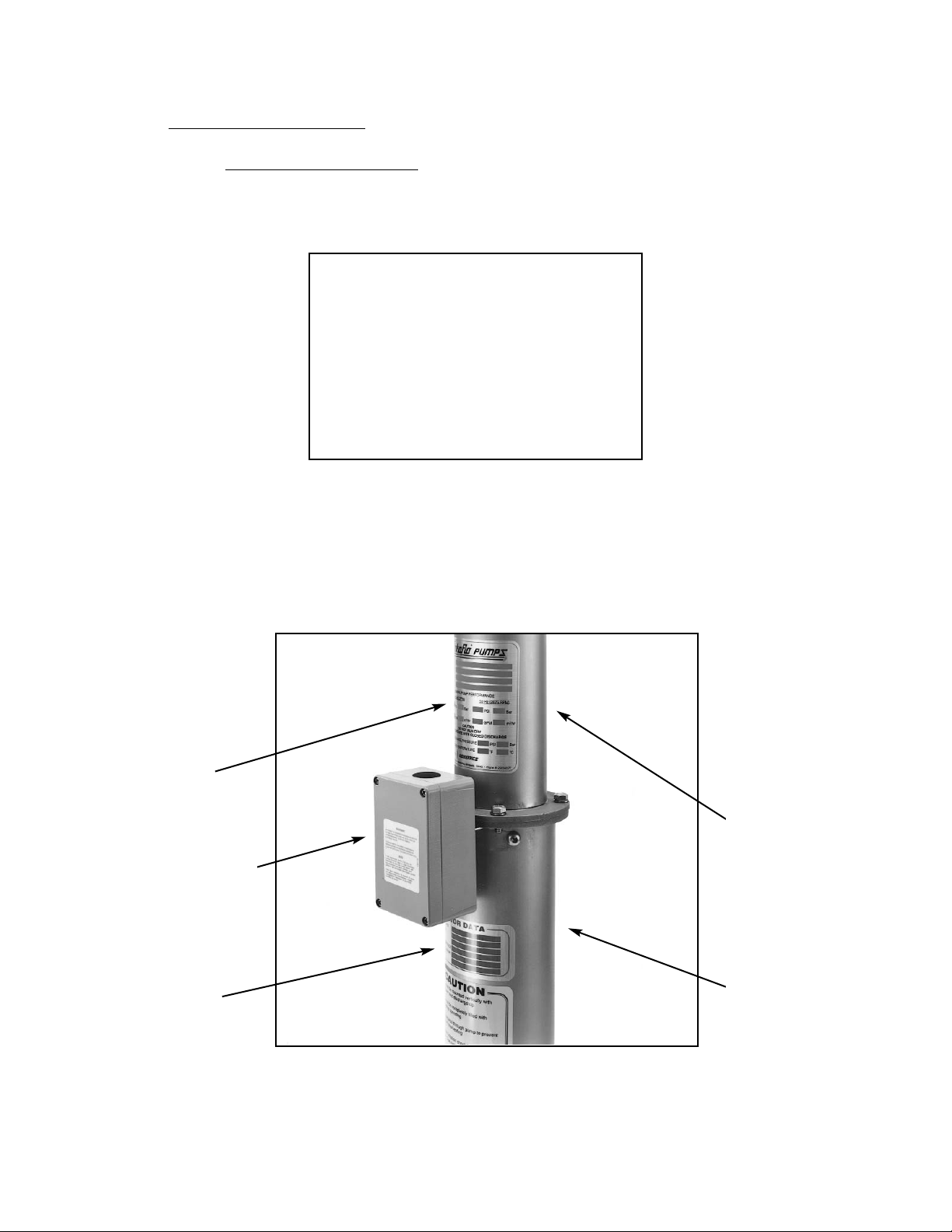
2.1 Pump Label Nomenclature
All Tonkaflo pumps use the same model number nomenclature to describe the
series name, nominal flow rate, staging and operation of the pump.
The pump label, showing model number, serial number, construction and
performance, is located immediately downstream from the electrical junction box on
the top side of the liquid end shell. The motor label, showing horsepower, voltage, Hz,
rated amp draw, service factor and service factor amps (S.F.A.), is located immediately upstream from the junction box on the top side of the motor module.
Figure 2.1 (Pump Label and Motor Label) shows these locations.
Figure 2.1
Pump and Motor Labels
2
Pump Label
Liquid End
Junction Box
Motor Label
Motor Module
Model QS2825V - 50
QS = Quiet Submersible
28 = Series 2800
25 = Stages
V = Vertical Operation Only
50 = 50 Hz Operation Only
Page 9
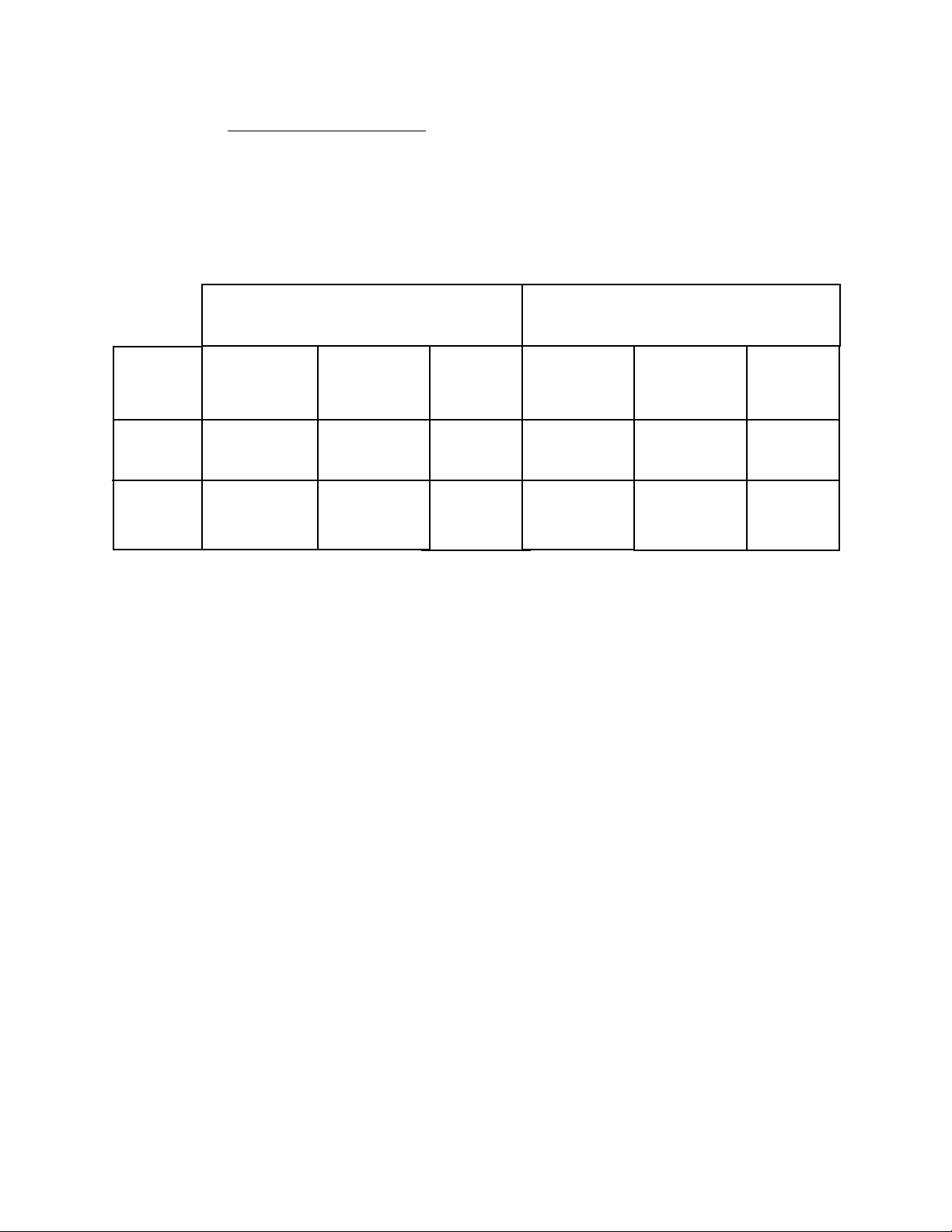
2.2 Performance Specifications
2.2.1 Pump Performance
Table 2.1
Pump Performance
Summary
*
Standard model pumps shown. Higher pressures are available upon request.
2.2.2 All QSV Pumps - IMPORTANT!
There is no limit on pumping capacity when operating QSV pumps in parallel.
The discharge pressure of your QSV pump may be increased by 100 psig (6.9
barg) by connecting another pump in series ahead of the QSV pump. Care
must be taken, however, so that the inlet pressure to any QSV pump does not
exceed the 100 psig (6.9 barg) maximum inlet pressure rating.
There must be adequate flow through the pump at all times to prevent excessive heat build-up.
3
Series
QS1800V
QS2800V
Max.
Efficiency
56%
64%
Max.
Efficiency
57%
51%
Capacity
gpm (m3/h)
5 - 21
(0.25 - 1.1)
10 - 40
(2.3 - 9.1)
Maximum
Boost*
psi (bar)
420 (29.0)
350 (24.1)
Capacity
gpm (m
3
/h)
7 - 15
(1.6 - 3.4)
9 - 34
(2.0 - 7.7)
Maximum
Boost*
psi (bar)
280 (19.3)
245 (16.9)
60 Hz Operation
(3450 rpm)
50 Hz Operation
(2875 rpm)
Page 10

2.3 Materials Specifications
Liquid End
Wetted Castings: 316 Stainless Steel
Pump Shell and Shaft: 316 Stainless Steel
Stages: Noryl*
O-Ring Seals and Shaft Bearings: Buna-N Rubber
Motor Module
Power Requirements 1-Phase
208, 230 V (60 Hz Operation)
220, 230, 240V (50 Hz Operation)
3-Phase
208, 230, 460, 575V (60 Hz Operation)
220, 380, 400, 415V (50 Hz Operation)
Motor Adapter and Inlet Flow Tube: 316 Stainless Steel
O-Ring Seals: Buna-N Rubber
Motors: Stainless steel shaft and stator shell,epoxy-
encapsulated stator, electroless nickle-plated
cast iron or Noryl plastic-covered carbon
steel stator ends, bronze filter check valve,
nitrile and neoprene rubber seals
Wire Insulation: Neoprene, chloroprene, hypalon, and/or poly-
olefin epoxy-potted
Antifreeze: 20% Propylene glycol (non-toxic)
80% Water
W
ARNING: 90°F (32°C) MAXIMUM OPERATING TEMPERATURE
Special Liquids:
Tonkaflo pumps can handle a variety of liquids. For liquids other than water; aqueous solutions or corrosive solutes, consult your local Tonkaflo distributor or factory.
Special Materials of Construction:
Ethylene propylene dimonomer (EPDM) and Teflon* pump shaft bears are available
for some models. Contact your distributor or the factory.
4
*Teflon is a trademark of E.I. DuPont de Nemours and Company, Inc.
Page 11

3.0 PUMP INSTALLATION
3.1 Inspection
Your pump was inspected and tested at the factory prior to shipment to ensure it
meets the requirements of your order. It is suggested the pump be checked upon
receipt for possible damage due to shipping. Any damage should be immediately
reported to the carrier.
3.2 Pump Mounting and Locations
The QSV Series pumps are intended for vertical mounting with the right angle inlet of
the pump down. See Figure 2 for correct orientation. The weight of the pump and
motor must be supported by setting the flat end of the outer housing on a rubber pad
supported by a plate or angle. Attach the pump to the frame work of your system
using ALL brackets included. Refer to Section 8.0 (Dimensional Drawing) for correct
bracket placement.
Figure 3.2
Right Angle Inlet and
Vertical Position
(QS2825V Shown)
5
Mounting Bracket
Right Angle Inlet
Page 12

3.3 Operation Safeguards
Quiet Submersible Vertical (QVS) Series pumps are equipped with NEMA standard
flow-cooled motors, which are cooled by the process fluid. In general, flow-cooled
motors have three requirements for long operational life. They are:
1. A suitable operating environment.
2. An adequate electrical supply.
3. An adequate flow of cooling water over the motor.
Quiet Submersible Vertical (QSV) Series pumps have been engineered to provide a
suitable mechanical operating environment and to provide an adequate flow of cooling water over the motor, provided the pump is operated between the maximum and
minimum flow rates specified for each pump series.
W
ARNING: CERTAIN SAFEGUARDS MUST BE IN PLACE TO PREVENT THE
FOLLOWING OPERATING CONDITIONS:
• Flow rate below minimum specified flow rate
• Close discharge valve (deadheaded condition)
• Dry running
• Fluid temperature greater than 90°F (32°C)
• Low voltage
• Imbalanced three-phase power
Safeguards include low-pressure switches, low-flow shutdown, switches, temperature limit switches, quick-trip circuit breakers and properly-sized motor starter
heaters. The three-phase electrical power must exhibit amperage readings in each
leg within ±5% of the average for all three legs (Section 3.6.3, Three-Phase Power
Imbalance). Consult the motor operation manual for additional information.
3.4 Inlet and Discharge -
IMP
ORTANT!
3.4.1 Inlet Piping
• Positive feed pressure is required at all flow points.
• Avoid “high points” and other areas where air may accumulate ahead of
the pump.
• The inlet piping should be at least as large as the inlet port; pipe size
changes should be tapered.
• Sizing pipe to induce 3 psi (0.21 bar) pressure drop or less per 100 feet
(30.5 m) is recommended.
• NE
VER throttle the pump on the inlet side.
• The pump inlet line should be filled and tested with 20 - 100 psi
(1.4 - 1.6 bar) pressure to detect any leaks prior to start-up.
6
Page 13

3.4.2 Discharge Piping
• Select piping to handle the maximum flow and pressure developed by
the pump.
• Sizing to induce 10 psi (0.70 bar) pressure drop or less per 100 feet
(30.5 m) is recommended.
3.4.3 Piping Connections
The standard QSV Series pump inlet and discharge connections are grooved
for Victaulic clamped-union couplings with gasket. The standard inlet and
discharge connection is 1-1/4-inch Victaulic. Victaulic couplings are available
worldwide. Contact the factory or your local industrial piping wholesaler.
3.4.4 Inlet Line Screen/Filter
This is a precision multi-stage pump with close tolerances to provide maximum efficiency. It is good practice to install a large area 30-mesh or finer
screen, or a cartridge filter in the pump inlet line to collect any foreign objects
or large particles. Size the screen or filter so as to induce a minimal pressure
drop.
W
ARNING: THE PUMP MUST NOT BE OPERATED WITH RESTRICTED SUC-
TION LINE (INLET) FLOW.
Positive gauge pressure must be maintained at the pump inlet (down stream
from the screen or filter). A clogged screen or filter will result in a greater pressure drop than a clean screen or filter. To prevent possible pump damage
from low inlet pressure, a low-pressure alarm or shut-off switch should be
located between the screen or filter and the pump. A low-flow shut-off switch
should also be located in the same area.
7
Page 14

3.4.5 Discharge Screen (Strainer)
A 30-mesh discharge screen (available as an accessory) located in the discharge piping will protect your process fluid should the pump be damaged.
The installation of the screen is shown in Figure 3.3 (Discharge Screen
Installation).
Figure 3.3
Discharge Screen
Installation
8
Pump
Victaulic
Clamp
Victaulic Gasket
Discharge Screen
(Cup Must Point
Towards Pump)
Page 15

3.5 Pump Priming - IMPORTANT!
QSV pumps are not designed to be self-priming.
WARNING: THE INLET PIPING, MOTOR MODULE AND PUMP LIQUID END MUST
BE COMPLETELY FILLED WITH LIQUID (PRIMED) BEFORE START-UP
(Figure 3.4, Priming Pump Level).
Figure 3.4
Priming Water Level
W
ARNING: THE PUMP MUST BE SHUT-OFF IMMEDIATELY IF PRIME IS LOST TO
AVOID POSSIBLE DAMAGE TO THE INTERNAL PARTS OF THE MOTOR
AND LIQUID END.
9
Discharge
Inlet
Water Level
Page 16

3.6 Motor Wiring
3.6.1 Single-Phase Motors - IMPORTANT!
Single phase three-wire motors require the use of a special controller included in a separate enclosure with each motor. The controller enclosure is not
attached to the motor. Operation of motors without the controller or using
the incorrect controller can result in failure of the motor and voids warranty.
The controller is mounted in a NEMA 4X enclosure and suitable for indoor or
outdoor applications within temperatures of 14°F (-10°C) to 122°F (50°C).
The controller should never be mounted in direct sunlight or high-temperature
locations as this will cause shortened capacitor life and unnecessary tripping
of the overload protector.
The controller enclosure is designed for vertical upright mounting only.
Mounting in other positions will affect its operation.
The controller must be electrically wired to the motor using minimum 8 AWG
for 5 horsepower motors and 10 AWG for 3 horsepower motors.
Figure 3.5
Two Sources of Power to
the Single-Phase Controller
The controller must be supplied with two sources of power. The control circuit
(motor starter coil) must be electrically wired with 110 VAC-50 Hz or 120 VAC60 Hz voltage. The power circuit must be electrically wired with single-phase
to match the motor label.
10
Page 17

3.6.2 Three-Phase Motors - IMPORTANT!
BEFORE STARTING THREE-PHASE MOTORS
STEPS
1. Prime pump before applying power to avoid damage to the pump and
motor.
2. Check the direction of rotation.
Three-phase motors can run in either direction, depending on how
they are connected to the power supply. When the three cable leads
are first connected to the power supply, there is a 50% chance that
the motor will run in the proper direction. To make sure the motor
running in the proper direction, carefully follow the next procedure:
Figure 3.6
Changing Motor Rotation
STEPS
A. Start the pump and note the pressure and flow rate developed
at the pump discharge.
B. Stop the pump and interchange any of the two leads (Figure
3.6, Changing Motor Rotation).
C. Start the pump again and re-check the flow rate and pressure.
D. Compare the results observed. The wire connection that
yielded the highest pressure and flow rate is the proper connection. Interchange the two leads again only if necessary.
11
Page 18

3.6.3 Three-Phase Power Imbalance
Current imbalance should not exceed 5% of the average three-phase
current. The current imbalance can be calculated as follows:
STEPS
1. Measure the current through each of the three legs.
2. Determine the average of the three currents.
3. Determine the difference between the current in each leg and the
average of all three legs.
4. Take the difference with the largest value, and divide it by the average
current. Multiply by 100 to obtain the current imbalance percentage.
5. If the current imbalance is greater than 5%, “roll” the leads and re-test
(Figure 3.7, “Rolling” the Leads to Balance Current Draw). If “rolling” the
leads does not correct the problem, the source of the imbalance must
be located and corrected. For more information on current imbalance, refer to the motor operation manual.
Figure 3.7
“Rolling” the Leads to
Balance Current Draw
3.6.4 Wire Sizing
For correct power lead sizing from the power source to controls and motor,
refer to the motor installation manual or local electrical codes.
12
Page 19

3.7 Electrical Grounding
W
ARNING: ELECTRICALLY GROUND THIS UNIT PRIOR TO START-UP.
Failure to do so may result in serious injury or death!
Verify there is electrical continuity between the motor module and the junction box
using a volt-ohm meter (Figure 2.1, Pump and Motor Labels). The junction box must
be grounded to an earth ground following local electrical codes. Grounding lugs are
provided within the junction box for this purpose. Check the continuity of your ground
connection to the motor module using a volt-ohm meter.
The motor module flange may also be directly connected to an earth ground.
3.8 Mot
or Protection - IMPORTANT!
Warranty on the flow-cooled motor is void unless proper quick-trip ambient compensated protection is used on all three motor lines. Subtrol may be used on pumps with
Franklin Motors. Refer to the motor installation manual.
13
Page 20

4.0 PUMP OPERATION
Review Section 2.0 (Tonkaflo Specifications) and Section 3.0 (Pump Installation) before operating your pump.
4.1 Priming
Prime the pump as noted in Section 3.5 (Pump Priming).
4.2 Operation
Operate the pump within its specified flow range. Failure to do so may damage the
motor or liquid end. Refer to the Performance Specifications (Section 2.2) or the performance curve supplied with your pump.
CA
UTION: Do not run pump dry or without sufficient heads.
The pump shall not be operated with an inlet pressure less than
20 psi (1.4 bar).
Do not deadhead pump.
The pump shall not be operated below the minimum or above the
maximum capacity specified for your particular model
(Table 2.1, Pump Performance Summary).
Do not exceed 90°F (32°C) operating fluid temperature.
The pump may be flushed with sanitizing water provided no power is
supplied to the motor.
4.3 Restarts -
IMP
ORTANT!
A maximum of 100 starts per day is recommended
Motors should be allowed to run one minute to dissipate heat build-up from starting
current
14
Page 21

5.0 GENERAL TROUBLESHOOTING
This troubleshooting guide can assist you in identifying common operating problems you
may experience with your machine. The operator can easily correct may of these problems,
however, for those that persist or are not understood you should contact the GE Customer
Support Center. Have the following information available when calling the Customer Support
Center:
1. Machine installation date
2. Model number
3. Serial number
4. Detailed description of problem.
15
REMEDIES
The pump inlet should be
piped to induce minimal pres-
sure drops through piping
diameter changes, elbows,
instrumentation, etc. QSV
pumps should NEVER be
throttled at the inlet. Check
discharge screen for
obstructions.
Verify no debris is clogging
screen or filter.
Make sure the discharge
valve is open enough to keep
the pump running on the per-
formance curve.
Fluid motion in your inlet pip-
ing may draw air into the
pump if the piping is not
sealed properly. Air bubbles
will be visible in the discharge
line.
POSSIBLE CAUSES
Restrictions in the inlet or
discharge
Inlet strainer/filter plugged
Discharge throttling valve
closed (pump deadheaded)
Air leak in inlet piping
PROBLEM
Low flow
TROUBLESHOOTING GUIDE
Page 22

16
REMEDIES
QSV pumps are not designed
to “lift” or “pull” fluid from a
tank. QSV pumps must be fed
with positive pressure [at
least 20 psi (1.4 bar)]. This
may be accomplished either
by having positive head from
the tank or incorporating a
transfer pump.
Make sure the motor is spin-
ning in the proper direction.
Prime the pump by filling all
inlet piping, including the
pump, with the process fluid.
Make sure your pump is oper-
ating within the flow range
specified by the pump per-
formance summary table or
the performance curve
included with the pump.
Verify no debris is clogging
the inlet screen or filter.
Fluid motion in your inlet pip-
ing may draw air into the
pump if the piping is not
sealed properly. Air bubbles
will be visible in the discharge
line.
Make sure the motor is spin-
ning in the proper direction.
Reverse two of the leads if
necessary.
POSSIBLE CAUSES
Suction lift too high
Reverse rotation of motor
Pump not adequately
primed
Excessive flow
Clogged suction into filter or
screen
Air leak in the inlet piping
Reverse rotation of motor
PROBLEM
Low flow
(continued)
TROUBLESHOOTING GUIDE
Page 23

17
REMEDIES
Verify the fuses are not
blown, a circuit breaker has
not tripped (also check the
breaker for controls), and the
heaters are not overloaded.
The wiring, heater switches
and starter must be inspected
for possible damage prior to
starting.
Make sure the motor is wired
across the proper voltage.
The required voltage is indi-
cated on the motor label.
With the circuit de-energized,
check for continuity using an
ohmmeter.
Confirm the circuit is wired for
single-phase or three-phase
and the motor is grounded.
Check safety shut-off circuitry
to make sure the necessary
circuit by-passes are in place
to start the motor.
Check single-phase motor
controller and verify that it is
in working order. See detailed
label inside controller box.
Check the amp draw through
each leg leading to the motor
using an ammeter. The read-
ings should not exceed the
maximum amps (S.F.A.) indi-
cated on the motor label.
POSSIBLE CAUSES
Blown fuse, tripped circuit
breaker or overloaded
Line voltage connection dif-
ferent from motor voltage
Bad connection
Motor wired improperly
Shut-off controls disabling
circuit.
Single-phase motor controller
not operational
Motor exceeding rated amp
draw
PROBLEM
Motor does not run
Motor runs, then stops
TROUBLESHOOTING GUIDE
Page 24

18
REMEDIES
Measure the current draw to
verify it is below the trip set-
ting. Increase the heater size
or adjust the trip setting to
correspond to the S.F.A. indi-
cated by the motor label.
QVS pumps are designed to
pump water. Consult the fac-
tory for liquids other than
water.
With the pump filled with the
process fluid, use a megohm
meter to measure the resist-
ance between each motor
lead and ground first at low
voltage, then at a potential
between 500 and 1000V if the
low-voltage test indicates an
open circuit. Consult the
motor installation and main-
tenance manual for accept-
able values.
With the circuit de-energized,
check for continuity using an
ohmmeter.
Confirm the circuit is wired for
single-phase or three-phase
power and the motor is
grounded.
Make sure the three legs of
your three-phase power are
balanced within ±5% of each
other.
POSSIBLE CAUSES
Motor starter heater size
too small
Specify gravity of liquid or
viscosity greater than
design
Water short in motor
electrical lead
Bad connection
Motor wired improperly
Three-phase current
imbalance
PROBLEM
Motor runs, then stops
(continued)
TROUBLESHOOTING GUIDE
Page 25

19
REMEDIES
Confirm both the pump liquid
end and motor module are
firmly secured to a rigid
structure.
QSV pumps must be fed with
positive pressure [at least
20 psi (1.4 bar). Check to
make sure there are no
obstructions, constrictions,
high points, or clogged filters
ahead of the pump.
QSV pumps must operate in
the flow range specified by
the performance summary
table or the pump perform-
ance curve.
Seal threaded fittings with
Teflon tape. Make sure gas-
kets are properly seated in
Victaulic or flanged fittings.
Replace the O-ring if possible,
or return the pump to the
factory for repair.
POSSIBLE CAUSES
Improper mounting
Starved suction line
Operating off the
performance curve
Piping not properly sealed
O-rings in pump casing or
motor module damaged
PROBLEM
Pump/motor vibrates
Pump leaks
TROUBLESHOOTING GUIDE
Page 26

6.0 FIELD MAINTENANCE
6.1 Flow-Cooled Mot
or and Liquid End - Tonkaflo Service Policy
WARNING: FIELD SERVICE OF THE FLOW-COOLED MOTOR OR LIQUID IS NOT
RECOMMENDED. If a liquid end is damaged by running the pump dry,
inadequate flow, deadheading, cavitation or other reasons, return it
with the motor to the factory for repair. The motor module and liquid
end may be separated for easier shipping. See Section 6.2 (Liquid End
Removal and Installation) for liquid end removal.
If a repair at the factory is desired, call the factory for a Return Goods Authorization
(RGA) number and follow the directions provided by a GE Customer Service representative. See Section 7.0 [Return Goods Authorization (RGA) Procedure] for more details.
6.2 Liquid End Remov
al and Installation
WARNING: DISCONNECT POWER SOURCE BEFORE ATTEMPTING ANY TYPE OF
FIELD SERVICE. FAILURE TO DO SO MAY RESULT IN SERIOUS INJURY
OR DEATH!
Figure 6.8
Liquid End and
Motor Module
(QS2825V Shown)
20
Liquid End
Remove Bolts
and Washers
(4PL)
Motor Module
Page 27

To separate the liquid end from the motor module, simply remove the four bolts joining the
two together (Figure 6.8, Liquid End and Motor Module) and carefully pull them apart (Figure
6.10, Liquid End Removal). To rejoin the liquid end to the motor module, use the following procedure: (Figures 6.9 and 6.10 detail the components and assembly).
STEPS
1. Lubricate the O-ring with petroleum or silicone grease
2. Align the splines on the liquid end coupling to the splines on the motor, and join
together using the four cap screws and lock washers. Do not over-tighten.
21
Figure 6.9
Removing Liquid End
(QS2825V Shown)
Figure 6.10
Liquid End Removal
(QS2825V Shown)
Pull Liquid End
Straight Out
Motor Module
Liquid End
Page 28

22
Figure 6.11
Component Detail
(QS2825V Shown)
Figure 6.12
Rejoining Liquid End
to Motor Module
(QS2528V Shown)
Liquid End
Coupling
O-Ring
Motor Shaft
Align Splines
and Pull
Together
Replace
Washers and Bolts
Page 29

7.0 TONKAFLO PUMP RETURN GOODS AUTHORIZATION (RGA) PROCEDURE
If you wish to return goods for repair, warranty evaluation and/or credit, please have your
original sales order or invoice available when you call GE. Call (800) 848-1750 and ask to
speak with Customer Service. A Customer Service representative will provide instructions and
a Return Goods Authorization (RGA) number which needs to be clearly written on the outside
of the box used to ship your materials. All equipment must be shipped to GE with the freight
prepaid by the customer. Call our Customer Service Center with any questions or issues concerning freight claims and a representative will discuss your situation.
All mat
erials to be returned must be rendered into a non-hazardous condition prior to
shipping.
There are two ways to handle a return: (1) send in the pump for repair and return or (2) purchase a new pump and when desired, send the defective pump to the factory for repair and
return.
7.1 Mot
or Warranty
Mot
ors must be sent to the nearest authorized motor service cent
er for repair,
replacement, and warranty disposition.
7.2 In-W
arranty Pump Failure
7.2.1 Return the defective pump to the factory for repair on an RGA within fifteen
(15) days. GE absorbs the cost of repair. The repaired pump will be returned
and remains under warranty for the remainder of the original warranty period or three months, whichever is longer.
7.2.2 GE will not restock or issue return credit against a new, non-stock, pump purchase regardless of the warranty status of the failed pump. The warranty
(Section 10.0) is 12 months from installation or 15 months from receipt,
whichever occurs first .
7.3 Out
-of-Warranty Pump Failure
Return the pump on an RGA for repair. The pump will be repaired and repair charges
invoiced to the customer. The warranty on repairs is three months.
7.4 Shipping Charges
7.4.1 In-Warranty
Customer pays for shipment to GE. GE pays one way surface freight return
to customer.
7.4.2 Out-of-Warranty When New Pump is Purchased
Customer pays all shipping charges.
23
Page 30

24
8.0 DIMENSIONAL DRA
WING
Figure 8.13
QS1800V and
QS2800V Series
Page 31

9.0 REPLACEMENT PARTS
9.1 P
arts Schematic
Figure 9.14
Parts Schematic
25
Page 32

9.2 Parts List, Standard Models
* Specify pump model.
9.3 Accessories for QS Series Tonkaflo Pumps
26
1
2
3
4
5
6
7
8
9
10
11
12
13
14
15
16
Liquid End Module
Shell Support Assembly
Clamp
Motor Module
Rubber Pad
Lock Washer
Screw
Lock Washer
Screw, Cap, Hex
Electrical Enclosure
Gasket
Nut, Electrical
Nut, PVC
Screw
Bracket
Nipple Assembly
*
1125211
1122861
*
1125199
1149629
1123200
1149629
1156215
1125267
1112276
1111878
1125312
1158439
1125268
1125313
Item
Number
QS1800V
QS2800V
Part
Number
Part Description
Part
Number
1110597
1113653
1120797
1120229
1120264
1123394
Part Description
Victaulic Coupling, 1.25-inch (31.8 mm), Style 77, Buna-N
Adapter, 1.25-inch (318. mm), Victaulic x 1.25-inch (31.8 mm), FNPT, 316SS
Adapter, 1.25-inch (318. mm), Victaulic x 1.0-inch (25.4 mm), FNPT, 316SS
Adapter, 1.25-inch (318. mm), Victaulic x 0.75-inch (19.1 mm), FNPT, 316SS
Pump Discharge Screen
QS Series Operation and Maintenance Manual
Page 33

9.4 Ordering Parts
Order parts through your local distributor or directly from:
GE Infrastructure
Water & Process Technologies
5951 Clearwater Drive
Minnetonka, MN 55343-8995
USA
Phone: (952) 933 - 2277
Fax: (952) 933 - 0141
Toll Free: (800) 848 - 1750
To order parts, the following information is necessary:
1. Pump model number
2. Pump serial number (from nameplate)
3. Other nameplate information, such as, operating temperature or material
code, and type of mechanical seal
4. Motor horsepower, motor frame size, and enclosure specifications
5. Part name
6. Part number
7. Quantity desired
8. Special materials of construction, if any.
27
Page 34

10.0 WARRANTY
GE warrants its pumps to be free from defects in design, material, or workmanship for a period of 15 months from receipt or 12 months from installation of the product, whichever occurs
first , when said products are operated in accordance with written instructions and are
installed properly. If Tonkaflo pumps are altered or repaired without prior approval of GE, all
warranties are void. If any defects or malperformance occur during the warranty period, GE's
sole obligation shall be limited to alteration, repair or replacement at GE’s expense, F.O.B. factory, of parts or equipment which, upon return to GE and upon GE’s examination, prove to be
defective. Equipment and accessories not manufactured by GE are warranted only to the
extent of and by the original manufacturer's warranty. GE shall not be liable for damage or
wear to equipment caused by abnormal conditions, excessive temperatures, vibration, failure to properly prime or to operate equipment without flow, or caused by corrosives, abrasives or foreign objects. The foregoing warranty is exclusive and in lieu of all other warranties,
whether expressed or implied including any warranty of merchantability or fitness for any
particular purpose. In no event shall GE be liable for consequential or incidental damages.
28
PUMP MODEL NUMBER:
PUMP SERIAL NUMBER:
P/N 1123394 Rev. D
Page 35

Page 36

For more information call 952-933-2277 or 800-848-1750 in the U.S., or visit www.gewater.com.
© 2005, General Electric Company. All rights reserved.
P/N 1123394 Rev. D
North American Sales Euro/Africa Sales Asia/Pacific Sales
5951 Clearwater Drive 230 rue Robert Schurman 1044/8 SOI 44/2
Minnetonka, MN ZA des Uselles Sukhumvit Road Parkanog
55343-8995 77350 Le Mée sur Seine Bangkok 10110
USA FRANCE THAILAND
(952) 933-2277 Phone +33 1 64 10 2000 Phone +66 2 38 14213 Phone
(952) 933-0141 Fax +33 1 64 10 3747 Fax +66 2 39 18183 Fax
GE Infrastructure
Water & Process Technologies
 Loading...