

Page 1
GEAppliances
ISee Bulletin TB11-15 1
I stall tio I
Bottom Freezer- Dispenser
WR02×25031
Kit Parts List:
Tank & Valve Tray
Ice Box Door Assembly
Cold Water Tank
Hot Water Tank Inlet Tube
Electrical Shock Hazard
Failure to adhere to this important safety notice
can result in serious injury or death.
• Repairs must be performed by a qualified
Se_ice Professional.
• Disconnect power before servicing this product.
• Reconnect all grounding devices after service.
, Replace all parts and panels before operating.
structio
Door Replacement Kit
6 - 1/4" hex head screws
2 - Ice Port Gasket Collars
Tank & Valve cover
Bottom Left Door Bin
Decal- Door Modification
Notice
GE & Profile - Removal of Exterior Parts
.
Disconnect power from appliance.
2.
Pull refrigerator out from wall.
3.
Place a towel on floor to absorb water.
4.
Disconnect water line from rear of refrigerator at quick connector, leaving connector on tube from
isolation valve. (in machine compartment)
.
Remove dispenser tray at the bottom of the recess.
6.
Remove tray guard (above tray if present) by removing 1/4" screw from underside.
7.
Remove User Interface and disconnect connectors.
8.
Disengage cold tube from ice chute.
9.
Ice chute removal:
a. Older models flex retaining tabs and pull ice chute forward.
b. Newer models have 2 -1/4" screws holding the ice chute.
10.
Disconnect duct door motor connector.
11.
Note location and position of duct door spring and motor then pull duct door motor forward with 2
fingers then slide to right to disengage it from recess.
12.
Flex either tab at top of dispenser paddle to release it at top, then lift up to remove.
13.
With a 1/8 in. hex key loosen 2 handle screws to remove handle.
14.
Remove 2 - T30 (3/16" hex} handle fasteners from LH door. NOTE: Profile models have a washer under
the bottom fastener.
GE Appliances
Louisville, KY 40225
GEAppliances.com
239D4772PO01 Rev. 0
Page 2
Disconnect power before performing the following service procedure.
Caf_ - Removal of Exterior Parts
.
Disconnect power from appliance.
2.
Pull refrigerator out from wall
3.
Place a towel on floor to absorb water.
4.
Disconnect water line from rear of refrigerator at quick connector, leaving connector on tube
from isolation valve. (in machine compartment)
.
Remove dispenser tray at the bottom of the recess.
6.
Remove tray guard by removing 1/4" from underside.
7.
Remove top trim from User Interface by pulling up and out on the top starting at the left side.
(Sometimes a fair amount of force may be necessary)
.
If the hot water knob or ring snap out of place push it back in.
9.
Remove 4 - 114" screws from recess housing, pull forward then disconnect the 2 connectors on
left.
10.
Disengage both cold and hot water tubes from ice chute.
11.
Ice chute removal:
a. Older models flex retaining tabs and pull ice chute forward.
b. Newer models have 2 - 114" screws holding the ice chute and retainer.
Disconnect duct door motor connector.
12.
13.
Note location and position of duct door spring and motor then pull duct door motor forward
with 2 fingers then slide to right to disengage it from recess.
14.
Flex either tab at top of dispenser paddle to release it at top, then lift up to remove.
15.
Remove the water filter access door on right edge of door. (not on all models)
16.
With a 118 in. hex key loosen 2 handle screws to remove handle.
17.
Remove 2 - T30 (3116" hex) handle fasteners from LH door.
Top of the Door (all]
i.
Remove 1A in. screws from hinge cover and roll it back to expose top hinge, electrical
connectors and inlet water line to door. On newer models with 3 piece hinge cover only remove
left hinge cover.
.
Disconnect lz_ in. ground screw from top hinge.
3.
Disconnect zz_in. screw from tubing spring clamp noting clamp's orientation.
4.
Pull water line out of conduit that runs to rear of refrigerator. Cut cable tie around harness and
inlet water tube.
.
Remove spring and clamp.
6.
Disconnect AC and DC door harness connectors.
7.
Remove 3 - T15 screws securing door board assembly.
8.
Lift up assembly to disengage door board from door.
9.
Disconnect all electrical connectors from door board
Page 3
Ice Box Disassembly (all)
.
Remove storage bins from inside of LH door. (bottom bin will not be reused)
2.
Remove ice bucket from ice box and discard ice.
3.
Close and latch ice box door.
4.
Remove 2 - T15 screws from ice box top hinge, unlatch door and lift up to remove ice box door and
discard door. Keep one of the screws for reassembly. (Lower ice box door hinge remains and will not be
used on the new door.)
.
Remove the screw holding electrical cover and pull forward then pull thermistor from inside of cover if
thermistor is still attached.
.
Disconnect electrical connectors for icemaker and auger motor.
7.
Remove 5116 in. screw at bottom of icemaker. On earlier models there is also a 5116 in. screw to the
right. Now pick up on icemaker to release it from rear tabs.
.
Remove the 2 - 5/16 in. screws holding the auger motor and pull forward.
9.
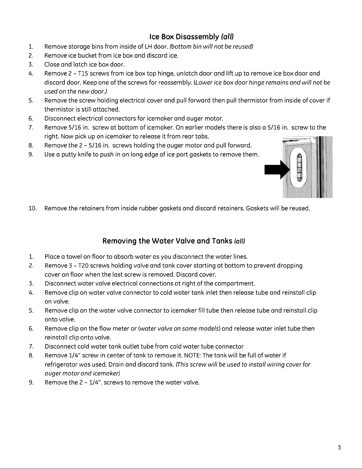
Use a putty knife to push in on long edge of ice port gaskets to remove them.
10. Remove the retainers from inside rubber gaskets and discard retainers. Gaskets will be reused.
Removing the Water Valve and Tanks lall;
.
Place a towel on floor to absorb water as you disconnect the water lines.
2.
Remove 3 - T20 screws holding valve and tank cover starting at bottom to prevent dropping
cover on floor when the last screw is removed. Discard cover.
.
Disconnect water valve electrical connections at right of the compartment.
4.
Remove clip on water valve connector to cold water tank inlet then release tube and reinstall clip
on valve.
.
Remove clip on the water valve connector to icemaker fill tube then release tube and reinstall clip
onto valve.
.
Remove clip on the flow meter or (water valve on some models) and release water inlet tube then
reinstall clip onto valve.
.
Disconnect cold water tank outlet tube from cold water tube connector
8.
Remove 1/4" screw in center of tank to remove it. NOTE: The tank will be full of water if
refrigerator was used. Drain and discard tank. (This screw will be used to install wiring cover for
auger motor and icemaker)
.
Remove the 2 - 1/4". screws to remove the water valve.
Page 4
Caf_ Hot Water Tank Removal
1. Disconnect hot water tank electrical connections at right of the compartment.
2. Use 2 small screw drivers to push down on connector collet to release hot water tank from
hot water outlet tube.
3. To complete removal of hot water tank, remove clip from hot water outlet on water valve,
then release tube by pushing up on collet.
4. Remove hot water tank inlet tube and discard.
5. Reinstall clips on valve so as not to lose it. Water lines can be installed with clips in place.
NOTE: Hold onto tank so as not to drop it. The tank will be full of water if refrigerator was used.
Door Removal (all)
.
Remove 3 - 3/8 in. bolts holding the top hinge.
2.
Remove top hinge from the door
3.
Open door to 90° and lift up on door to release it from lower hinge mounted to case.
4.
Lay door on a flat protected surface.
Final Disassembly (all)
.
Remove 2 - T15 screws from electrical connector cover of articulating mullion to expose
electrical connector disconnect.
.
Slide mullion toward top of door to remove it.
3.
Remove door gasket by pulling dart of gasket out of groove in door.
4.
Remove 2 - T20 screws to remove door stop.
5.
Remove 1/4" screw to remove door closure mechanism.
4
Page 5
Installation
Door prep (all)
.
Install door closure mechanism and door stop.
2.
Install door gasket with small flaps to the handle side of door.
3.
Align articulating mullion with top and bottom tabs and slide it toward the bottom of the door.
4.
Reconnect articulating mullion connector place cover into position and install 2 - T15 screws.
Mounting Door On The Case (all)
.
Hold door 90 °to cabinet to align bottom hinge with door closure and allow door to drop down on
hinge pin.
.
Put 2 wire bundles in slot in top hinge align door so 2 locating pins engage small holes in hinge then
start 3 - 3/8 in. hex bolts. Note: Always start these 3 bolts by hand to prevent stripping of threads
then use o driver or socket wrench to run in the bolts
.
Tighten properly with o 3/8" socket wrench.
Top of the door (all)
.
Reconnect all of electrical connectors to door board assembly starting at right end.
2.
Seat board into position and install 3 - T15 screws.
3.
Put spring and strain relief clamp on fill tube then insert tube into conduit to the rear of
refrigerator.
.
Position strain relief clamp so tubing will be routed to right of the screw.
5.
Install 1/4" screw to top hinge screw hole closest to front.
6.
Reinstall door ground wire to rear screw hole of top hinge.
7.
Reconnect both AC and DC harness connectors to connectors on hinge cover.
8.
Use cable tie around both harnesses and water line spring to route properly.
9.
Roll hinge cover over hinges into position or install left hinge cover. Watch wiring harness and
connectors making sure they stay in their proper place. Make sure there no wires at any of screw
holes to prevent driving a screw through them causing a short.
10.
Install 1/4" screws securing the hinge cover to the top.
New Ice box door Installation (all]
.
Install auger motor with 2 -5/16 inch screws
2.
Hang icemoker on the 2 tabs in ice box and install 5/16 inch screw at the bottom of mold.
3.
Connect electrical connector to icemoker and auger motor. Make sure ice box thermistor is pulled
out of junction box
.
Place ice box thermistor in molded mount in cover or mount in door liner, place cover over wiring
connectors ond instoll screw thot wos removed from originol cold woter tonk. (2"white screw with
1/4" head)
.
Set new ice box door on pre-molded bottom hinge, latch door and attach top hinge with 1 - T15
screw
.
Reinstall ice auger bucket.
7.
Install 2 new ice port gasket retainers into the 2 ice port gaskets then install gaskets.
Page 6
Caf_ User Interface and Handles
i.
Put the 2 tabs on bottom of the dispenser paddle into 2 holes in recess.
2.
Snap 2 top tabs of paddle into place keeping wires to left.
3.
Position spring on duct door then put left of shaft into hole in recess.
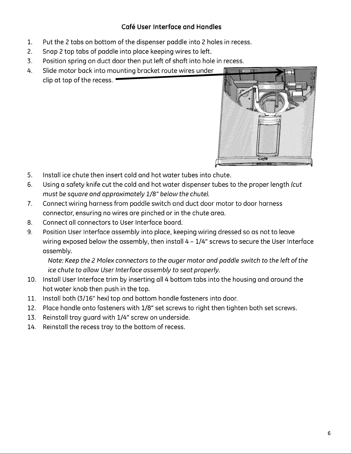
4.
Slide motor back into mounting bracket route wires under
clip at top of the recess.
5. Install ice chute then insert cold and hot water tubes into chute.
6. Using a safety knife cut the cold and hot water dispenser tubes to the proper length (cut
must be square and approximately 1/8" below the chute).
7. Connect wiring harness from paddle switch and duct door motor to door harness
connector, ensuring no wires are pinched or in the chute area.
8. Connect all connectors to User Interface board.
9. Position User Interface assembly into place, keeping wiring dressed so as notto leave
wiring exposed below the assembly, then install 4 - 114" screws to secure the User Interface
assembly.
Note: Keep the 2 Molex connectors to the auger motor and paddle switch to the left of the
ice chute to allow User Interface assembly to seat properly.
i0. Install User Interface trim by inserting all 4 bottom tabs into the housing and around the
hot water knob then push in the top.
ii. Install both (3116" hex) top and bottom handle fasteners into door.
12. Place handle onto fasteners with 118" set screws to right then tighten both set screws.
13. Reinstall tray guard with 114" screw on underside.
14. Reinstall the recess tray to the bottom of recess.
6
Page 7
GE & Profile Recess, User Interface and Handles
.
Put the 2 tabs on bottom of the dispenser paddle into 2 holes in recess.
2.
Snap 2 top tabs of paddle into place keeping wires to left.
3.
Position spring on duct door then put left side of shaft into hole in recess.
4.
Slide motor back into mounting bracket route wires.
5.
Install ice chute then insert cold and hot water tubes into chute.
6.
Route Duct door motor harness in front of ice chute.
7.
Using a safety knife cut the cold water dispenser tube to the proper length (cut must be square
and approximately 1/8" below the chute).
.
Connect wiring harness from paddle switch and duct door motor to door harness connector,
ensuring no wires are pinched or in the ice chute area.
.
Connect all connectors to User Interface board.
10.
Position User Interface assembly into place, keeping wiring dressed so as not to leave wiring
exposed below the assembly, then snap into place.
Note: Keep the 2 Molex connectors to the auger motor and paddle switch to the left of the ice
chute to allow User Interface assembly to seat properly.
10.
Install both T30 (3/16" hex) top and bottom handle fasteners into door. NOTE: Profile models
hove a washer under the bottom fastenen
11.
Place handle onto fasteners with 1/8" set screws to right then tighten both set screws.
12.
Reinstall tray guard (if present) with 1/4" screw on underside.
13.
Reinstall the recess tray to the bottom of recess.
Page 8

¢af Tank &Valve Tray
%" mounting screws
New longer Hot Water
Tank Connector
(factory installed on new door)
Front View
Unction Box for 6-pin
Hot Water Tank
Connector
Hot Water Tank
Inlet Tube
Retainer
Hot Water Tank
Wiring
Harness and
Tubing Area
Hot Water Tank
Outlet
Cold Water Tank
Outlet
Cold Water Tank Outlet
Connector
(factory installed on new door
(black tube)
Hot Water Tank Inlet
Tube Retainer
Rear View
Water Supply
Inlet Tube
(gray tube)
Hot Water Tank
Inlet Tube
New longer Hot Water Tank
Connector
(factory installed on new door)
retainers
Page 9

Caf_ Valve and Tank Installation
.
Tank & Valve tray has new cold water tank attached.
2.
Connect cold water tank outlet tube to 90 ° quick connector already installed on door.
3.
Move all of tubing and wiring harness to right to align with the slot in right side of tank tray,
place tubes and wiring in slot as connected in the following steps.
.
Pull hot water tank 6-pin DC wiring harness from upper left junction box.
5.
Using 2 supplied 1/4" screws mount Tank & Valve Tray to the door with holes at the top.
6.
Connect the cold water tank inlet tube to center outlet on water valve.
7.
Attach water valve to tray by using the slot on left then slide to right to lock in place with
tab on the right.
Slot for Triple Locking Tab
valve
.
Disconnect male to female 90° quick connector on outlet of hot water tank and discard. (do
not reuse this connector, the one already installed is longer) Installed on
Discard new door
.
Push quick connector on outlet of hot water tank onto male end of connector already
installed on hot water tube in the door making sure it is fully seated.
i0.
Place hot water tank onto tray and press downward to clip in place.
ii.
Connect 6 pin DC harness and route connector into junction box at top right of tray.
12.
Connect 3 pin AC harness and route it to right side of hot water tank.
13.
Connect water valve connector to AC harness.
14.
Connect flow meter harness to wiring harness.
15.
Connect inlet water tube to water flow meter on right end of valve.
16.
Connect IM fill tube to right angled outlet on water valve.
17.
Dress all tubing and harnesses in opening on right side of Tank & Valve tray.
18.
Install short end of new hot water inlet tube to leftmost outlet on water valve and other end
to inlet of hot water tank.
19.
Route same new hot water tube through 2 retaining clips in tray, one on bottom of tray
below the water valve and one mid-high on right side of tray.
Go to Final Steps on pg.
Page 10

GEProfileTank &ValveTray
Front View
1_,, mounting screws
Wiring
Harness and
Tubing Area
Water Supply
Inlet Tube
_gray tube)
Cold Water Tank
Outlet
Cold Water Tank Outlet
Connector
(factory installed on new door)
Outlet
_black tube)
Rear View
Water Tank retainers
10
Page 11

GE & Profile Valve and Tank Installation
.
Tank & Valve tray has new cold water tank attached.
2.
Connect cold water tank outlet tube to 90 ° quick connector.
3.
Move all of tubing and wiring harness to right to align with the slot in right side of tank tray, place
tubes and wiring in slot as connected in the following steps.
.
Using 2 supplied 1/4" screws mount Tank & Valve Tray to the door with holes at the top.
5.
Connect the cold water tank inlet tube to left port of water valve.
6.
Attach water valve to tray by using the slot on left toward the center then slide to right to lock in
place.
Slot for Locking Tab
double
7. Remove wiring harness from white clip on water valve for full use of length of harness then connect.
Water valve
clips
8. Connect water valve connector to AC harness.
9. Connect flow meter harness to wiring harness if present. (some models do not have flow meter)
10. Connect water tube to water valve inlet or flow meter on right end of valve.
11. Connect IM fill tube to right angled outlet on water valve.
12. Dress all tubing and harness in slot on right side of Tank & Valve tray.
Final Steps (all)
.
Reconnect water line to quick connector on back of refrigerator
2.
Reconnect power to refrigerator for the purposes of leak checking the Cold and Hot Water
Connections. Disconnect power to the refrigerator before performing any further repairs to the water or
electrical systems.
.
Fill cold water tank then dispense 6 large glasses of water and inspect for leaks.
4.
Fill Hot water tank.
5.
Operate the hot water feature at 185 degree or on Soup selection 3 times and inspect for leaks.
6.
Install new water valve and tank cover by:
a. Put cover in place about 1/2" down and slide up.
b. This will insert 4 tabs on the top inside of cover into slots at the top of the tray.
c. Install 2 - 1/4" screws provided into bottom screw holes.
d. Install 2 - 1/4" screws provided into side recess holes to complete cover installation.
.
Reuse 2 upper door bin modules on ice box door.
8.
Install new bottom left door bin on tank & valve cover. (New bin appearance may be different than
original)
.
Reinstall filter
10.
Reinstall filter door assembly.
11.
Ensure doors are even at the top, if not, adjust as needed so they are even.
12.
Place Door Modification Notice decal directly under the Model and Serial tag at the top right offf
interior.
11
Page 12

GEAppliances
ISee Bulletin TB11-15 1
I stall tio I
Bottom Freezer- Dispenser
WR02×25031
Kit Parts List:
Tank & Valve Tray
Ice Box Door Assembly
Cold Water Tank
Hot Water Tank Inlet Tube
Electrical Shock Hazard
Failure to adhere to this important safety notice
can result in serious injury or death.
• Repairs must be performed by a qualified
Se_ice Professional.
• Disconnect power before servicing this product.
• Reconnect all grounding devices after service.
, Replace all parts and panels before operating.
structio
Door Replacement Kit
6 - 1/4" hex head screws
2 - Ice Port Gasket Collars
Tank & Valve cover
Bottom Left Door Bin
Decal- Door Modification
Notice
GE & Profile - Removal of Exterior Parts
.
Disconnect power from appliance.
2.
Pull refrigerator out from wall.
3.
Place a towel on floor to absorb water.
4.
Disconnect water line from rear of refrigerator at quick connector, leaving connector on tube from
isolation valve. (in machine compartment)
.
Remove dispenser tray at the bottom of the recess.
6.
Remove tray guard (above tray if present) by removing 1/4" screw from underside.
7.
Remove User Interface and disconnect connectors.
8.
Disengage cold tube from ice chute.
9.
Ice chute removal:
a. Older models flex retaining tabs and pull ice chute forward.
b. Newer models have 2 -1/4" screws holding the ice chute.
10.
Disconnect duct door motor connector.
11.
Note location and position of duct door spring and motor then pull duct door motor forward with 2
fingers then slide to right to disengage it from recess.
12.
Flex either tab at top of dispenser paddle to release it at top, then lift up to remove.
13.
With a 1/8 in. hex key loosen 2 handle screws to remove handle.
14.
Remove 2 - T30 (3/16" hex} handle fasteners from LH door. NOTE: Profile models have a washer under
the bottom fastener.
GE Appliances
Louisville, KY 40225
GEAppliances.com
239D4772PO01 Rev. 0
Page 13

Disconnect power before performing the following service procedure.
Caf_ - Removal of Exterior Parts
.
Disconnect power from appliance.
2.
Pull refrigerator out from wall
3.
Place a towel on floor to absorb water.
4.
Disconnect water line from rear of refrigerator at quick connector, leaving connector on tube
from isolation valve. (in machine compartment)
.
Remove dispenser tray at the bottom of the recess.
6.
Remove tray guard by removing 1/4" from underside.
7.
Remove top trim from User Interface by pulling up and out on the top starting at the left side.
(Sometimes a fair amount of force may be necessary)
.
If the hot water knob or ring snap out of place push it back in.
9.
Remove 4 - 114" screws from recess housing, pull forward then disconnect the 2 connectors on
left.
10.
Disengage both cold and hot water tubes from ice chute.
11.
Ice chute removal:
a. Older models flex retaining tabs and pull ice chute forward.
b. Newer models have 2 - 114" screws holding the ice chute and retainer.
Disconnect duct door motor connector.
12.
13.
Note location and position of duct door spring and motor then pull duct door motor forward
with 2 fingers then slide to right to disengage it from recess.
14.
Flex either tab at top of dispenser paddle to release it at top, then lift up to remove.
15.
Remove the water filter access door on right edge of door. (not on all models)
16.
With a 118 in. hex key loosen 2 handle screws to remove handle.
17.
Remove 2 - T30 (3116" hex) handle fasteners from LH door.
Top of the Door (all]
i.
Remove 1A in. screws from hinge cover and roll it back to expose top hinge, electrical
connectors and inlet water line to door. On newer models with 3 piece hinge cover only remove
left hinge cover.
.
Disconnect lz_ in. ground screw from top hinge.
3.
Disconnect zz_in. screw from tubing spring clamp noting clamp's orientation.
4.
Pull water line out of conduit that runs to rear of refrigerator. Cut cable tie around harness and
inlet water tube.
.
Remove spring and clamp.
6.
Disconnect AC and DC door harness connectors.
7.
Remove 3 - T15 screws securing door board assembly.
8.
Lift up assembly to disengage door board from door.
9.
Disconnect all electrical connectors from door board
Page 14

Ice Box Disassembly (all)
.
Remove storage bins from inside of LH door. (bottom bin will not be reused)
2.
Remove ice bucket from ice box and discard ice.
3.
Close and latch ice box door.
4.
Remove 2 - T15 screws from ice box top hinge, unlatch door and lift up to remove ice box door and
discard door. Keep one of the screws for reassembly. (Lower ice box door hinge remains and will not be
used on the new door.)
.
Remove the screw holding electrical cover and pull forward then pull thermistor from inside of cover if
thermistor is still attached.
.
Disconnect electrical connectors for icemaker and auger motor.
7.
Remove 5116 in. screw at bottom of icemaker. On earlier models there is also a 5116 in. screw to the
right. Now pick up on icemaker to release it from rear tabs.
.
Remove the 2 - 5/16 in. screws holding the auger motor and pull forward.
9.
Use a putty knife to push in on long edge of ice port gaskets to remove them.
10. Remove the retainers from inside rubber gaskets and discard retainers. Gaskets will be reused.
Removing the Water Valve and Tanks lall;
.
Place a towel on floor to absorb water as you disconnect the water lines.
2.
Remove 3 - T20 screws holding valve and tank cover starting at bottom to prevent dropping
cover on floor when the last screw is removed. Discard cover.
.
Disconnect water valve electrical connections at right of the compartment.
4.
Remove clip on water valve connector to cold water tank inlet then release tube and reinstall clip
on valve.
.
Remove clip on the water valve connector to icemaker fill tube then release tube and reinstall clip
onto valve.
.
Remove clip on the flow meter or (water valve on some models) and release water inlet tube then
reinstall clip onto valve.
.
Disconnect cold water tank outlet tube from cold water tube connector
8.
Remove 1/4" screw in center of tank to remove it. NOTE: The tank will be full of water if
refrigerator was used. Drain and discard tank. (This screw will be used to install wiring cover for
auger motor and icemaker)
.
Remove the 2 - 1/4". screws to remove the water valve.
Page 15

Caf_ Hot Water Tank Removal
1. Disconnect hot water tank electrical connections at right of the compartment.
2. Use 2 small screw drivers to push down on connector collet to release hot water tank from
hot water outlet tube.
3. To complete removal of hot water tank, remove clip from hot water outlet on water valve,
then release tube by pushing up on collet.
4. Remove hot water tank inlet tube and discard.
5. Reinstall clips on valve so as not to lose it. Water lines can be installed with clips in place.
NOTE: Hold onto tank so as not to drop it. The tank will be full of water if refrigerator was used.
Door Removal (all)
.
Remove 3 - 3/8 in. bolts holding the top hinge.
2.
Remove top hinge from the door
3.
Open door to 90° and lift up on door to release it from lower hinge mounted to case.
4.
Lay door on a flat protected surface.
Final Disassembly (all)
.
Remove 2 - T15 screws from electrical connector cover of articulating mullion to expose
electrical connector disconnect.
.
Slide mullion toward top of door to remove it.
3.
Remove door gasket by pulling dart of gasket out of groove in door.
4.
Remove 2 - T20 screws to remove door stop.
5.
Remove 1/4" screw to remove door closure mechanism.
4
Page 16

Installation
Door prep (all)
.
Install door closure mechanism and door stop.
2.
Install door gasket with small flaps to the handle side of door.
3.
Align articulating mullion with top and bottom tabs and slide it toward the bottom of the door.
4.
Reconnect articulating mullion connector place cover into position and install 2 - T15 screws.
Mounting Door On The Case (all)
.
Hold door 90 °to cabinet to align bottom hinge with door closure and allow door to drop down on
hinge pin.
.
Put 2 wire bundles in slot in top hinge align door so 2 locating pins engage small holes in hinge then
start 3 - 3/8 in. hex bolts. Note: Always start these 3 bolts by hand to prevent stripping of threads
then use o driver or socket wrench to run in the bolts
.
Tighten properly with o 3/8" socket wrench.
Top of the door (all)
.
Reconnect all of electrical connectors to door board assembly starting at right end.
2.
Seat board into position and install 3 - T15 screws.
3.
Put spring and strain relief clamp on fill tube then insert tube into conduit to the rear of
refrigerator.
.
Position strain relief clamp so tubing will be routed to right of the screw.
5.
Install 1/4" screw to top hinge screw hole closest to front.
6.
Reinstall door ground wire to rear screw hole of top hinge.
7.
Reconnect both AC and DC harness connectors to connectors on hinge cover.
8.
Use cable tie around both harnesses and water line spring to route properly.
9.
Roll hinge cover over hinges into position or install left hinge cover. Watch wiring harness and
connectors making sure they stay in their proper place. Make sure there no wires at any of screw
holes to prevent driving a screw through them causing a short.
10.
Install 1/4" screws securing the hinge cover to the top.
New Ice box door Installation (all]
.
Install auger motor with 2 -5/16 inch screws
2.
Hang icemoker on the 2 tabs in ice box and install 5/16 inch screw at the bottom of mold.
3.
Connect electrical connector to icemoker and auger motor. Make sure ice box thermistor is pulled
out of junction box
.
Place ice box thermistor in molded mount in cover or mount in door liner, place cover over wiring
connectors ond instoll screw thot wos removed from originol cold woter tonk. (2"white screw with
1/4" head)
.
Set new ice box door on pre-molded bottom hinge, latch door and attach top hinge with 1 - T15
screw
.
Reinstall ice auger bucket.
7.
Install 2 new ice port gasket retainers into the 2 ice port gaskets then install gaskets.
Page 17

Caf_ User Interface and Handles
i.
Put the 2 tabs on bottom of the dispenser paddle into 2 holes in recess.
2.
Snap 2 top tabs of paddle into place keeping wires to left.
3.
Position spring on duct door then put left of shaft into hole in recess.
4.
Slide motor back into mounting bracket route wires under
clip at top of the recess.
5. Install ice chute then insert cold and hot water tubes into chute.
6. Using a safety knife cut the cold and hot water dispenser tubes to the proper length (cut
must be square and approximately 1/8" below the chute).
7. Connect wiring harness from paddle switch and duct door motor to door harness
connector, ensuring no wires are pinched or in the chute area.
8. Connect all connectors to User Interface board.
9. Position User Interface assembly into place, keeping wiring dressed so as notto leave
wiring exposed below the assembly, then install 4 - 114" screws to secure the User Interface
assembly.
Note: Keep the 2 Molex connectors to the auger motor and paddle switch to the left of the
ice chute to allow User Interface assembly to seat properly.
i0. Install User Interface trim by inserting all 4 bottom tabs into the housing and around the
hot water knob then push in the top.
ii. Install both (3116" hex) top and bottom handle fasteners into door.
12. Place handle onto fasteners with 118" set screws to right then tighten both set screws.
13. Reinstall tray guard with 114" screw on underside.
14. Reinstall the recess tray to the bottom of recess.
6
Page 18

GE & Profile Recess, User Interface and Handles
.
Put the 2 tabs on bottom of the dispenser paddle into 2 holes in recess.
2.
Snap 2 top tabs of paddle into place keeping wires to left.
3.
Position spring on duct door then put left side of shaft into hole in recess.
4.
Slide motor back into mounting bracket route wires.
5.
Install ice chute then insert cold and hot water tubes into chute.
6.
Route Duct door motor harness in front of ice chute.
7.
Using a safety knife cut the cold water dispenser tube to the proper length (cut must be square
and approximately 1/8" below the chute).
.
Connect wiring harness from paddle switch and duct door motor to door harness connector,
ensuring no wires are pinched or in the ice chute area.
.
Connect all connectors to User Interface board.
10.
Position User Interface assembly into place, keeping wiring dressed so as not to leave wiring
exposed below the assembly, then snap into place.
Note: Keep the 2 Molex connectors to the auger motor and paddle switch to the left of the ice
chute to allow User Interface assembly to seat properly.
10.
Install both T30 (3/16" hex) top and bottom handle fasteners into door. NOTE: Profile models
hove a washer under the bottom fastenen
11.
Place handle onto fasteners with 1/8" set screws to right then tighten both set screws.
12.
Reinstall tray guard (if present) with 1/4" screw on underside.
13.
Reinstall the recess tray to the bottom of recess.
Page 19

¢af Tank &Valve Tray
%" mounting screws
New longer Hot Water
Tank Connector
(factory installed on new door)
Front View
Unction Box for 6-pin
Hot Water Tank
Connector
Hot Water Tank
Inlet Tube
Retainer
Hot Water Tank
Wiring
Harness and
Tubing Area
Hot Water Tank
Outlet
Cold Water Tank
Outlet
Cold Water Tank Outlet
Connector
(factory installed on new door
(black tube)
Hot Water Tank Inlet
Tube Retainer
Rear View
Water Supply
Inlet Tube
(gray tube)
Hot Water Tank
Inlet Tube
New longer Hot Water Tank
Connector
(factory installed on new door)
retainers
Page 20

Caf_ Valve and Tank Installation
.
Tank & Valve tray has new cold water tank attached.
2.
Connect cold water tank outlet tube to 90 ° quick connector already installed on door.
3.
Move all of tubing and wiring harness to right to align with the slot in right side of tank tray,
place tubes and wiring in slot as connected in the following steps.
.
Pull hot water tank 6-pin DC wiring harness from upper left junction box.
5.
Using 2 supplied 1/4" screws mount Tank & Valve Tray to the door with holes at the top.
6.
Connect the cold water tank inlet tube to center outlet on water valve.
7.
Attach water valve to tray by using the slot on left then slide to right to lock in place with
tab on the right.
Slot for Triple Locking Tab
valve
.
Disconnect male to female 90° quick connector on outlet of hot water tank and discard. (do
not reuse this connector, the one already installed is longer) Installed on
Discard new door
.
Push quick connector on outlet of hot water tank onto male end of connector already
installed on hot water tube in the door making sure it is fully seated.
i0.
Place hot water tank onto tray and press downward to clip in place.
ii.
Connect 6 pin DC harness and route connector into junction box at top right of tray.
12.
Connect 3 pin AC harness and route it to right side of hot water tank.
13.
Connect water valve connector to AC harness.
14.
Connect flow meter harness to wiring harness.
15.
Connect inlet water tube to water flow meter on right end of valve.
16.
Connect IM fill tube to right angled outlet on water valve.
17.
Dress all tubing and harnesses in opening on right side of Tank & Valve tray.
18.
Install short end of new hot water inlet tube to leftmost outlet on water valve and other end
to inlet of hot water tank.
19.
Route same new hot water tube through 2 retaining clips in tray, one on bottom of tray
below the water valve and one mid-high on right side of tray.
Go to Final Steps on pg.
Page 21

GEProfileTank &ValveTray
Front View
1_,, mounting screws
Wiring
Harness and
Tubing Area
Water Supply
Inlet Tube
_gray tube)
Cold Water Tank
Outlet
Cold Water Tank Outlet
Connector
(factory installed on new door)
Outlet
_black tube)
Rear View
Water Tank retainers
10
Page 22

GE & Profile Valve and Tank Installation
.
Tank & Valve tray has new cold water tank attached.
2.
Connect cold water tank outlet tube to 90 ° quick connector.
3.
Move all of tubing and wiring harness to right to align with the slot in right side of tank tray, place
tubes and wiring in slot as connected in the following steps.
.
Using 2 supplied 1/4" screws mount Tank & Valve Tray to the door with holes at the top.
5.
Connect the cold water tank inlet tube to left port of water valve.
6.
Attach water valve to tray by using the slot on left toward the center then slide to right to lock in
place.
Slot for Locking Tab
double
7. Remove wiring harness from white clip on water valve for full use of length of harness then connect.
Water valve
clips
8. Connect water valve connector to AC harness.
9. Connect flow meter harness to wiring harness if present. (some models do not have flow meter)
10. Connect water tube to water valve inlet or flow meter on right end of valve.
11. Connect IM fill tube to right angled outlet on water valve.
12. Dress all tubing and harness in slot on right side of Tank & Valve tray.
Final Steps (all)
.
Reconnect water line to quick connector on back of refrigerator
2.
Reconnect power to refrigerator for the purposes of leak checking the Cold and Hot Water
Connections. Disconnect power to the refrigerator before performing any further repairs to the water or
electrical systems.
.
Fill cold water tank then dispense 6 large glasses of water and inspect for leaks.
4.
Fill Hot water tank.
5.
Operate the hot water feature at 185 degree or on Soup selection 3 times and inspect for leaks.
6.
Install new water valve and tank cover by:
a. Put cover in place about 1/2" down and slide up.
b. This will insert 4 tabs on the top inside of cover into slots at the top of the tray.
c. Install 2 - 1/4" screws provided into bottom screw holes.
d. Install 2 - 1/4" screws provided into side recess holes to complete cover installation.
.
Reuse 2 upper door bin modules on ice box door.
8.
Install new bottom left door bin on tank & valve cover. (New bin appearance may be different than
original)
.
Reinstall filter
10.
Reinstall filter door assembly.
11.
Ensure doors are even at the top, if not, adjust as needed so they are even.
12.
Place Door Modification Notice decal directly under the Model and Serial tag at the top right offf
interior.
11
 Loading...