

GE Dryer, PVXR373EHWW Use And Care Manual
With Installation Instructions
500A280P018
Use and Care Guide
Dryer
S afety Instruc tio ns................. 3, 4
Installatio n Instruc t io ns
E x h au st ............................................6 , 7
E le c tric D ry e r.......................................8
G as D ry e r ........................................8 , 9
R e v e rsib le D o o r In stru c tio n s .............5
O p erating Instruc tio ns,T ip s
A u to m atic D ry in g ..............................13
C o lo r L o g ic .........................................11
D ry in g Se le c tio n G u id e ..............12 , 13
E le c tro n ic Se n so r C o n tro l ................13
E x tra C are P ro g ram ....................10 , 12
K n it s D ry in g Tip s .........................11, 12
L in t F ilte r ............................................11
L o ad in g ........................................11, 16
O p e ratin g th e D ry e r..........10 , 11, 12 , 13
P e rm an e n t P re ss
D ry in g Tip s ................................11, 16
So rtin g C lo t h e s ............................11, 12
Sp e c ial In stru c tio n s ..........................12
Tim e d D ry in g ..............................12 , 13
E n d C y c le Sig n al ...............................10
Care and Cleaning
D ru m Stain le ss Ste e l........................14
D ry e r E x h au st ....................................15
E x te rio r ...............................................11
L ig h t B u lb R e p lac e m e n t ...................13
L in t F ilte r ............................................11
P ro b lem S o lv er ........................ 16
Co nsum er S erv ic es
Mabe Se rv ic e Te le p h o n e N u m b e rs ...17
M o d e l an d Se rial N u m b e rs................2
R e p air Se rv ic e .....................................2
W arran ty ............................................18
F o r serv ic e c all:
1 -8 0 0 -3 6 1 -3 4 0 0
www.g ea p p lia n c es.c a
We care about our environment.
R E C Y C L E D P A P E R
R E C Y C L A B L E
Note to Consum er:
This product was verified to be in excellent condition when it left our m anufacturing facility. If it has been
dam aged during transit or installation, please report that dam age im m ediately to the Retail Outlet where it
was purchased. Although your warranty covers m anufacturing defects in m aterial or workm anship, it does
not include coverage for delivery dam age. Please refer to your warranty section for specific inform ation
about warranty term s and conditions.
Read this book carefully.
It is in ten ded to help you op erate an d
m ain tain your n ew dryer p rop erly.
K eep it han dy for an swers to your
q uestion s.
S ave tim e an d m on ey.
B efore you req uest service...
check the P roblem S olver section , it
lists causes of m in or op eratin g
p roblem s that you can correct
yourself.
For further in form ation you can call us.
Mab e ’s service p hon e n um bers are
listed on p ag e 1 7 .
If you received a
dam ag ed dryer...
Im m ediately con tact the dealer ( or
builder) that sold you the dryer.
W rite down the m odel an d
serial n um bers.
Y ou’ll fin d them on a label on the
fron t of the dryer behin d the door.
T hese n um bers are also on the
C on sum er P roduct O wn ership
Reg istration C ard that cam e with
your dryer. B efore sen din g in this
card, p lease write these n um bers
here:
Model Number
Serial Number
U se these n um bers in an y
corresp on den ce or service calls
con cern in g your dryer.
Mab e S ervice C on tracts
Y our n ew dryer is a well desig n ed an d en g in eered p roduct.
B efore it left the factory, it wen t throug h rig orous tests,
just to m ake sure it was as p roblem -free as p ossible. A n d
you have a warran ty to p rotect you ag ain st m an ufacturin g
p roblem s durin g the p eriod of your dryer warran ty.
Mab e S ervice C on tracts are available to p rovide the
sam e trouble-free service for as lon g as you own your
ap p lian ce. S hould your ap p lian ce req uire service after the
warran ty has ex p ired, a Mab e S ervice C on tract takes
care of an y rep airs your ap p lian ce n eeds – both p arts an d
labour.
For further in form ation about Mab e ’s service p hon e
n um bers, refer to p ag e 1 7 .
2
HELP US HELP YOU
W A RN IN G : For your safety the in form ation in this m an ual m ust be followed to m in im iz e the risk of
fire or ex p losion or to p reven t p rop erty dam ag e, p erson al in jury or death.
– D o n ot store or use g asolin e or other flam m able
vap ors an d liq uids in the vicin ity of this or an y
other ap p lian ce.
– W H A T T O D O IF Y O U S M E L L G A S
• D o n ot try to lig ht an y ap p lian ce.
• D o n ot touch an y electrical switch;
do n ot use an y p hon e in your buildin g .
• C lear the room , buildin g or area of all
occup an ts.
• I m m ediately call your g as sup p lier from a
n eig hbor’s p hon e. Follow the g as sup p lier’s
in struction s.
• I f you can n ot reach your g as sup p lier, call the
fire dep artm en t.
– I n stallation an d service m ust be p erform ed by a
q ualified in staller, service ag en cy, or the g as
sup p lier.
I F YOU N EED SER V I C E...
Ple a s e C a ll: 1 -8 0 0 -3 6 1 -3 4 0 0

Warning - It is extremely important that you read and adhere to the
following instructions. Failure to do so could cause bodily injuries and /
or property damage due to fire.
Important Safety Instructions
3
IM PORT A NT SA FET Y INST RUCT IONS
Read all instructions b efore using th is appliance
• Use this appliance only for its intended purpose as
described in this Use and Care Book.
This dryer must be properly installed and
located in accordance with the Installation
Instructions before it is used.
– Properly ground to conform with Local Codes.
In the event of malfunction or breakdown, grounding
will reduce the risk of electric shock by providing a path
of least resistance for electric current. This appliance is
equipped with a cord having an equipment-grounding
conductor and a grounding plug. The plug must be
plugged into an appropriate outlet that is properly
installed and grounded in accordance with all local
codes and ordinances.
WARNING: Improper connection of the equipmentgrounding conductor can result in a risk of electric
shock. Check with a qualified electrician or service
representative or personnel il you are in doubt as to
whether the appliance is properly grounded.
Do not modify the plug provided with the appliance: if it
will not fit the outlet, have a proper outlet installed by a
qualified electrician.
Follow details in Installation
Instructions.
– Locate where the temperature is above 5 0 ˚F. (10 ˚C.) for
satisfactory operation of the dryer control system.
Do not install or store the dryer where it will be
exposed to the water and/or the weather.
– Connect to a properly rated, protected and sized
power supply circuit to avoid electrical overload.
– Exhausting to the outside is STRONGLY
RECOMMENDED to prevent large amounts of
moisture and lint from being blown into the room.
Carefully follow the Exhausting Details in the
Installation Instructions.
– A GAS DRYER MUST BE EX HAUSTED TO THE
OUTDOORS.
Do not repair or replace any part of the
appliance or attempt any servicing unless
specifically recommended in this Use and
Care Book or in published user-repair
instructions that you understand and have the skills
to carry out.
When disconnecting this appliance pull by the plug
rather than the cord to avoid damage to the
cord or junction of cord and plug. Make
sure that the cord is located so that it will
not be stepped on, tripped over or otherwise
subjected to damage or stress.
To Minimize the Possibility of a
Fire Hazard
• Exhaust Duct – See Installation Instructions. Use
only rigid metal or flexible metal 4 ” diameter
ductwork for exhausting to the outside. USE OF
PLASTIC OR OTHER COMBUSTIBLE
DUCTWORK CAN CAUSE A FIRE. FOIL OR
OTHER EASILY PUNCTURED DUCTWORK
CAN CAUSE A FIRE IF IT COLLAPSES OR
BECOMES OTHERWISE RESTRICTED IN USE
OR DURING INSTALLATION.
• Do not use heat to dry articles containing rubber,
plastic, or similar materials (such as padded bras,
tennis shoes, galoshes, bath mats, rugs, bibs, pillows,
baby pants, plastic bags, etc.) as these materials may
melt or burn. Also, some rubber materials, when
heated, can under certain circumstances produce fire
by spontaneous combustion.
• Do not store items that may burn or melt (such as
clothing, paper material, plastics or plastic
containers, etc.) on top of the dryer during the
operation.
• Garments labeled “ Dry Away from Heat” (such as
life jackets containing Kapok or foam) must not be
put in your dryer.
• Do not wash or dry articles that
have been cleaned in, washed in,
soaked in, or spotted with combustible
or explosive substances (such as wax,
paint, gasoline degreasers, dry-cleaning
solvents, kerosene, etc.) which may ignite or
explode. Do not add these substances to the wash
water. Do not use these substances around your
washer and/or dryer during operation.
• Any article on which you have used a cleaning
solvent, or which contains flammable materials (such
as cleaning cloths, mops, towels used in beauty
salons, restaurants or barber shops, etc.) must not be
placed in or near the dryer until all traces of these
flammable liquids or solids and their fumes have
been removed. There are many highly flammable
items used in homes such as: acetone, denatured
alcohol, gasoline, kerosene, some household
cleaners, some spot removers, turpentines, waxes,
wax removers and products containing petroleum
distillates.
(continued on next page)
• Clean the lint filter before each load
to prevent lint accumulation inside
the dryer or in the room.
DO NOT OPERATE THE DRYER
WITHOUT THE LINT FILTER IN
PLACE.
• Keep the area around and underneath your appliances
free from the accumulation of combustible materials,
such as lint, paper, rags, chemicals, gasoline and
other flammable vapors and liquids.
• Regularly inspect the exhaust duct to be sure it has
not been crushed or otherwise restricted.
• The interior of the dryer cabinet and the exhaust duct
connection inside the dryer should be cleaned every 2
to 3 years, or more often if needed, by a qualified
service person. (see Care & Cleaning section)
To Minimize the Possibility of Injury
• Never reach into the dryer while the drum is moving.
Before loading, unloading or adding clothes, wait
until the drum has completely stopped.
• Do not dry fiberglass articles in your dryer. Skin
irritation could result from the remaining glass
particles that may be picked up by clothing during
subsequent dryer uses.
• The laundry process can reduce the
flame retardance of fabrics. To avoid
such a result, the garment manufacturer’s
care instructions should be followed very
carefully.
• Close supervision is necessary if this
appliance is used by or near children.
Do not allow children to play inside,
on, or with this appliance or any
discarded appliance. Dispose of
discarded appliances and shipping or
packing materials properly. Before
discarding a dryer, or removing from
service, remove the door of the dryer compartment.
SAV E THESE
INSTRUCTIONS
• Keep all laundry aids (such as
detergents, bleaches, fabric softeners,
etc.) out of the reach of children,
preferably in a locked cabinet. Observe
all warnings on container labels to avoid
personal injury.
• Keep the floor around your appliances clean and dry
to reduce the possibility of slipping.
• To minimize the possibility of electric shock, unplug
this appliance from the power supply before
attempting any maintenance or cleaning
(except the removal and cleaning of the lint
filter).
• NOTE: Turning the Cycle Selector
knob to an OFF position does NOT
disconnect the appliance from the power
supply.
• Do not tamper with the controls.
• Do not operate this appliance if it is damaged,
malfunctioning, partially disassembled, or has
missing or broken parts, including a damaged cord or
plug.
• Never climb on or stand on the dryer top.
• DO NOT place items exposed to cooking oils in your
dryer. Items contaminated with cooking oils may
contribute to a chemical reaction that could cause a
clothes load to catch fire.
• If yours is a gas dryer, it is equipped with an
automatic electric ignition and does not have a pilot
light. DO NOT ATTEMPT TO LIGHT WITH A
MATCH. Burns may result from having your hand in
the vicinity of the burner when the automatic ignition
may turn on.
• Do not obstruct the flow of combustion and
ventilation air.
Dryer-applied Fabric Softeners or
Anti-static Conditioners
You may wish to soften your laundered fabrics or
reduce the static electricity in them. We recommend
you use either a fabric softener in the wash cycle,
according to the manufacturer’s instructions for those
products, or try a dryer-added product for which the
manufacturer gives written assurance on the package
that their product can be safely used in your dryer.
Service or performance problems caused by the use of
these products are the responsibility of the manufacturers
of those products and are not covered under the
warranty of this appliance.
4
IMPORTANT SAFETY INSTRUCTIONS
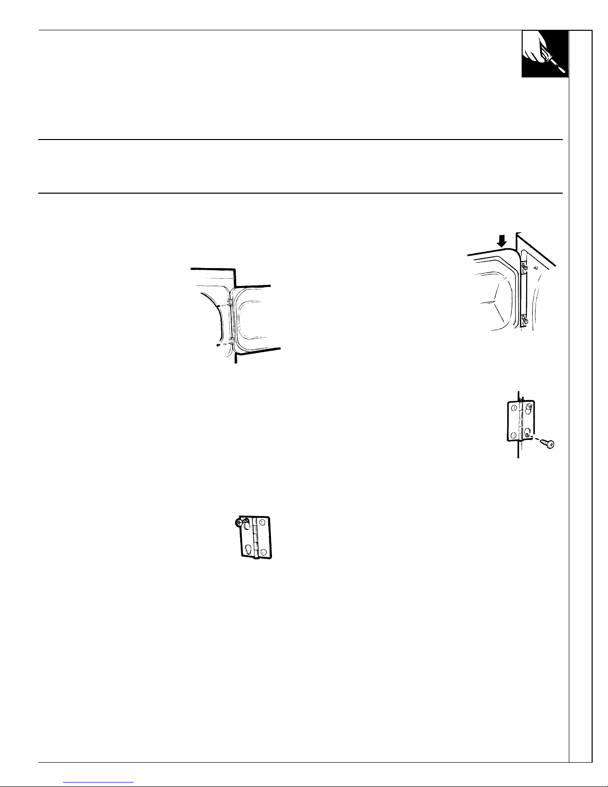
REVERSIBLE DOOR INSTRUCTIONS
These instructions are for changing the hinges from the
right side to the left side.
If you need to change the hinges from the left side to
the right side, follow these same instructions (merely
reverse all references to the left and right).
Tools Needed
Standard # 2 Phillips screwdriver
DRYER DOOR
1. Open the door and remove the filler plugs opposite the
hinges.
(A tape-tipped putty knife
or a needle-nosed plier
will help to remove the
plugs. Be careful not to
damage the paint.)
2 . With the door completely
open, remove the bottom
screw attaching each hinge
to the dryer front. (Do not
remove the screws located
on the door itself).
3. Insert these screws about half way into the top holes,
for each hinge, on the opposite side (where you
removed the filler plugs).
4. Loosen the remaining top screw
from each hinge on the dryer front,
half way.
5 . With one hand holding
the top of the door, and
the other hand holding
the bottom, remove the
door from the dryer
front by lifting it UP
and OUT.
6. Rotate the door 18 0˚.
Insert it on the opposite
door frame by moving the
door IN and DOWN until
the top hinge and the
bottom hinge are resting on
the top screws inserted in
step 3.
7 . With the other screws, secure
each hinge at the bottom.
8. Tighten the top screws of each
hinge.
9 . Reinsert the plastic plugs on the side from which the
door was removed.
5
Rev ersible Door Instructions
Installation and service must be performed by a qualified installer, service agency or the gas supplier.
IMPORTANT: Have your dryer installed properly.
NOTE: The WARNING and IMPORTANT instructions appearing in this manual are not meant to cover all possible
conditions and situations that may occur. It must be understood that common sense, caution, and carefulness are factors
that CANNOT be built into the dryer. These factors MUST BE supplied by the person(s) installing, maintaining, or
operating the dryer.
Failure to install, maintain, and/or operate this machine according to the manufacturer’s instructions may result in
conditions which can produce bodily injury and/or property damage.
6
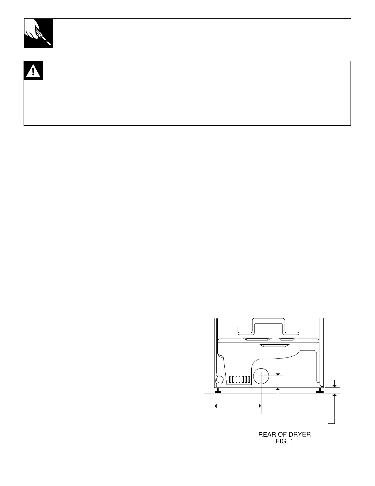
This dryer comes ready for rear exhausting (see Fig. 1).
WARNINGS
• DO NOT USE NON METALLIC FLEXIBLE DUCT.
• Never use flexible duct inside the dryer.
• Do not terminate exhaust in a chimney, range hood,
gas vent, floor or attic. The combination of lint and
grease could create a fire hazard or damages.
• Provide an access for inspection and cleaning the
exhaust system at least once a year. (See Care and
Cleaning Section.)
EXHAUST LENGTH
The MAXIMUM ALLOWABLE length of the exhaust
system depends upon the type of duct, number of turns,
the type of exhaust hood (wall cap), and all conditions
noted below. The maximum allowable length for both
rigid and flexible metal duct is shown in the table 1
(next page). More than four 9 0˚ turns is not
recommended.
EXHAUST SYSTEM CHECK LIST
HOOD or WALL CAP
• Terminate in a manner to prevent back drafts or entry
of birds or other wildlife.
• Termination should present minimal resistance to the
exhaust air flow and should require little or no
maintenance to prevent clogging.
• Wall caps must be installed at least 300 mm (12”)
above ground level or any other obstruction with the
opening pointed down.
• If roof vents or louvered plenums are used, they must
be equivalent to a 100 mm (4”) dampered wall cap in
regard to resistance to air flow, prevention of back
drafts and maintenance required to prevent clogging.
SEPARATION OF TURNS
Separate all turns by at least 1 m (3 ft.) of straight duct,
including distance between last turn and dampered wall
cap. If two turns must be closer than 1 m (3 ft.) deduct
3 m (10 ft.) from the maximum lengths shown in the
table for each occurrence.
TURNS OTHER THAN 9 0˚
• One turn of 45˚ or less may be ignored.
• Two 45˚ turns should be treated as one 9 0˚.
• Each turn over 45˚ should be treated as one 9 0˚.
SEALING OF J OINTS
• All joints should be tight to avoid leaks. The male
end of each section of duct must point away from the
dryer.
• Do not assemble the duct work with fasteners that
extend into the duct. They will serve as a collection
point for lint.
• Duct joints can be made air and moisture-tight by
wrapping the overlapped joints with duct tape.
INSULATION
• Duct work which runs through an unheated area or is
near an air conditioning duct, should be insulated to
reduce condensation and lint build up and be sloped
down toward outdoors.
NOTE: Never install screen inside exhaust duct.
CAUTION: THE DRYER MUST EXHAUST TO THE
OUTDOORS.
INSTALLATION INSTRUCTIONS
EX HAUST
298mm
(11 3/4")
91mm
(3 1/2")
NOTE: ADD TO
91mm (31/2")
THE DISTANCE
BETW EEN
CABINET BOTTO M
TO FLOOR SURFACE
Installation Instructions
7
INSTALLATION INSTRUCTIONS
EXHAUST
ALTERNATE EXHAUST DIRECTIONS
This dryer comes ready for rear exhausting. If space is limited, use the following instructions to exhaust
directly from the side or bottom of the cabinet.
GAS DRYER CAN NOT BE EXHAUSTED DIRECTLY THROUGH THE RIGHT SIDE OF THE CABINET.
WARNING: Protect your hands and arms when working inside the cabinet.
• Never use flexible duct inside dryer.
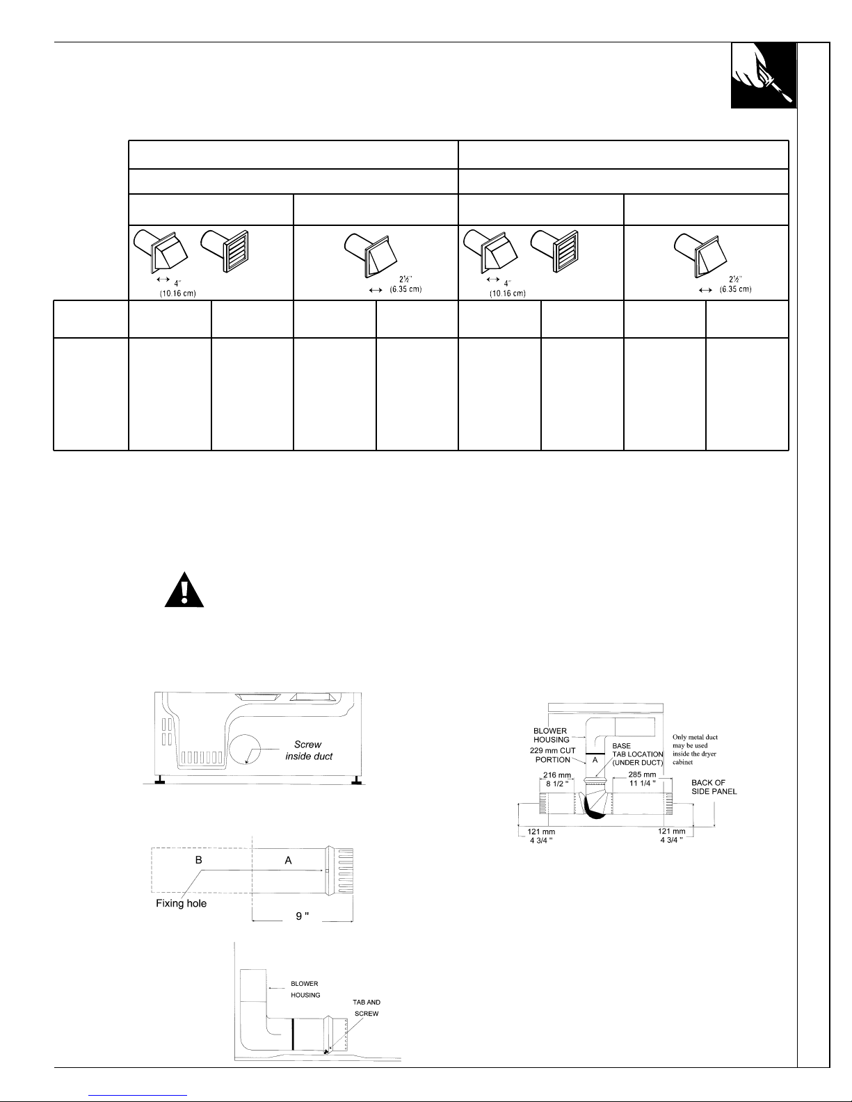
• Detach and remove the desired knockout.
• Remove the screw inside the dryer exhaust duct end.
Pull on the duct to remove it. Keep the screw for
later.
• Cut the duct as shown, 229 mm (9 inches).
Keep portion A.
• Through the rear
opening, locate the
tab in the middle of
the appliance base.
Lift the tab to about
45˚ using a flat
screwdriver.
• Reconnect and secure the cut portion (A) of the duct
to the blower housing. Make sure that the fixing
hole is aligned with the tab in the base. Use the
reserved screw to secure the duct in place through
the tab on the appliance base.
• Use a standard and adjustable metal elbow and a
metal straight duct to exhaust the dryer through the
knockout choosen. Insert standard elbow and ducts
through rear and side or bottom openings.
• Use only 100 mm (4 inch) diameter rigid metallic
duct.
• Cover the opening at the back with the plate (Kit
WE1M454) available from your Local Service
Provider.
WARNING: Nev er leav e the op ening at the back
without the p late.
Table 1: RECOMMENDED MAXIMUM LENGTH
ELECTRIC DRYERS GAS DRYERS
Weather Hood Type Weather Hood Type
Recommended
Use only for short
run installations
Recommended
Use only for short
run installations
No. of 90˚
elbows
Rigid
Metallic
Flexible*
Rigid
Metallic
Flexible*
Rigid
Metallic
Flexible*
Rigid
Metallic
Flexible*
0
1
2
3
4
27.4 m (90 ft.)
18.3 m (60 ft.)
13.7 m (45 ft.)
10.7 m (35 ft.)
7.6 m (25 ft.)
16.8 m (55 ft.)
12.2 m (40 ft.)
9.1 m (30 ft.)
6.1 m (20 ft.)
4.6 m (15 ft.)
18.3 m (60 ft.)
13.7 m (45 ft.)
10.7 m ( 35 ft.)
7.6 m (25 ft.)
4.6 m (15 ft.)
13.7 m (45 ft.)
9.1 m (30 ft.)
6.1 m (20 ft.)
4.6 m (15 ft.)
3.0 m (10 ft.)
13.7 m (45 ft.)
10.7 m (35 ft.)
7.6 m (25 ft.)
4.6 m (15 ft.)
–
9.1 m (30 ft.)
6.1 m (20 ft.)
3.0 m (10 ft.)
–
–
9.1 m (30 ft.)
6.1 m (20 ft.)
3.0 m (10 ft.)
–
–
4.6 m (15 ft.)
3.0 m (10 ft.)
–
–
–
* Do not use non metallic flexible duct.
8
INSTALLATION
IMPORTANT - OBSERVE ALL G OVERNING CODES
Dryer must be levelled and rest firmly on the floor.
SPECIAL INSTALLATION REQ UIREMENTS
ALCOVE OR CLOSET INSTALLATION
• The dryer MUST be exhausted to the outdoor. See
EXHAUST INFORMATION section.
• Minimum clearances between dryer cabinet and
adjacent walls or other surfaces are:
0 mm (0”) either side
76 mm (3”) front and rear
• Minimum vertical space from floor to overhead
cabinets, ceilings, etc. is 132 cm (52”).
NOTE: CONSIDERATION MUST BE GIVEN TO
INSTALLING AND SERVICING THE APPLIANCE.
• Closet door must be louvered or otherwise ventilated
and must contain a minimum of 387 cm
2
(60 in2) of
open area equally distributed. If this closet contains
both a washer and a dryer, doors must contain a
minimum of 774 cm
2
(120 in2) of open area equally
distributed.
• If yours is a gas dryer, the closet should be vented to
the outdoors to prevent gas pocketing in case of a gas
leak in the supply line.
• No other fuel-burning appliance shall be installed in
the same closet with the dryer.
MINIMUM CLEARANCES OTHER THAN ALCOVE
OR CLOSET INSTALLATIONS.
• Minimum clearances to combustible surfaces and for
air opening:
0 clearance both sides and 25 mm (1”) rear.
MOBILE HOME INSTALLATION
• The dryer must be exhausted to the outdoors with the
termination securely fastened to the mobile home
structure. (See EXHAUST INFORMATION section.)
• The exhaust MUST NOT be terminated beneath the
mobile home.
• The exhaust MUST NOT be connected to any other
duct, vent and chimney.
• Provisions must be made for the introduction of
outside air into the dryer room. The free air opening
shall not be less than 160 cm
2
(25 in2).
• The exhaust duct material MUST BE METAL.
• Do not connect the exhaust duct with sheet metal
screws or other fastening devices which extend to the
interior of the duct.
• The dryer must be attached to the floor following
instructions available from the dealer.
• Installation must comply with the current CAN/CSA
Z 240 MH series Mobile Home Installation Codes.
NOTE: CONSIDERATION MUST BE GIVEN TO
INSTALLING AND SERVICING THE APPLIANCE.
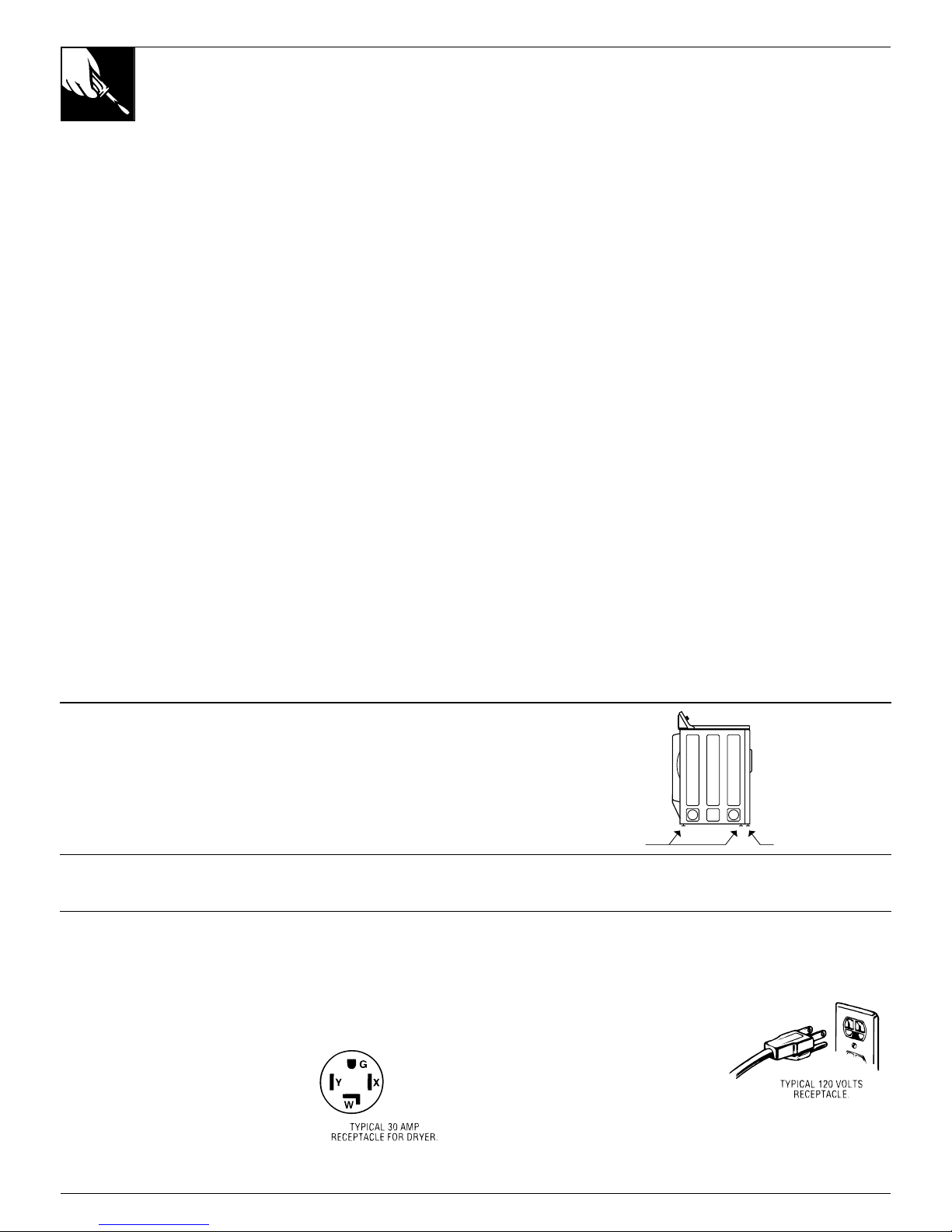
LEVELING THE DRYER
Adjust all 4 leveling legs to match washer height. Dryer
MUST BE LEVEL and rest firmly on all 4 leveling
legs.
If yours is a gas dryer, also adjust the two stabilizing
legs to contact the floor.
DUCT LENGTH
For maximum performance, refer to table for maximum allowable length of exhaust system (Exhaust section).
ELECTRICAL POWER SUPPLY
CAUTION: NEVER USE AN EXTENSION CORD WITH THIS APPLIANCE.
Note: If the electrical power supply provided does not meet the specifications listed below, call a licensed electrician.
FOR ELECTRIC DRYERS, POWER SUPPLY...
1. Must be of 120/240 volts or 120/208 volts, 60 Hz
circuit with wall receptacle as
shown beside.
2. Must be protected with 30A
FUSES OR BREAKERS.
3. Must be WELL GROUNDED.
4. Must CONFORM TO LOCAL
CODES.
FOR GAS DRYERS, POWER SUPPLY...
1. Must be of 120 volts, 60 Hz
circuit with wall receptacle as
shown beside.
2. Must be protected with 15 or
20A FUSES OR BREAKER.
3. Must be WELL GROUNDED.
4. Installation must be in accordance
with the current CSA C22.1 Canadian Electrical code
part 1 and/or local codes.
4 LEVELING
LEGS
TWO STABILIZING LEGS
(GAS DRYERS ONLY)
SIDE
VIEW
9
Installation Instructions
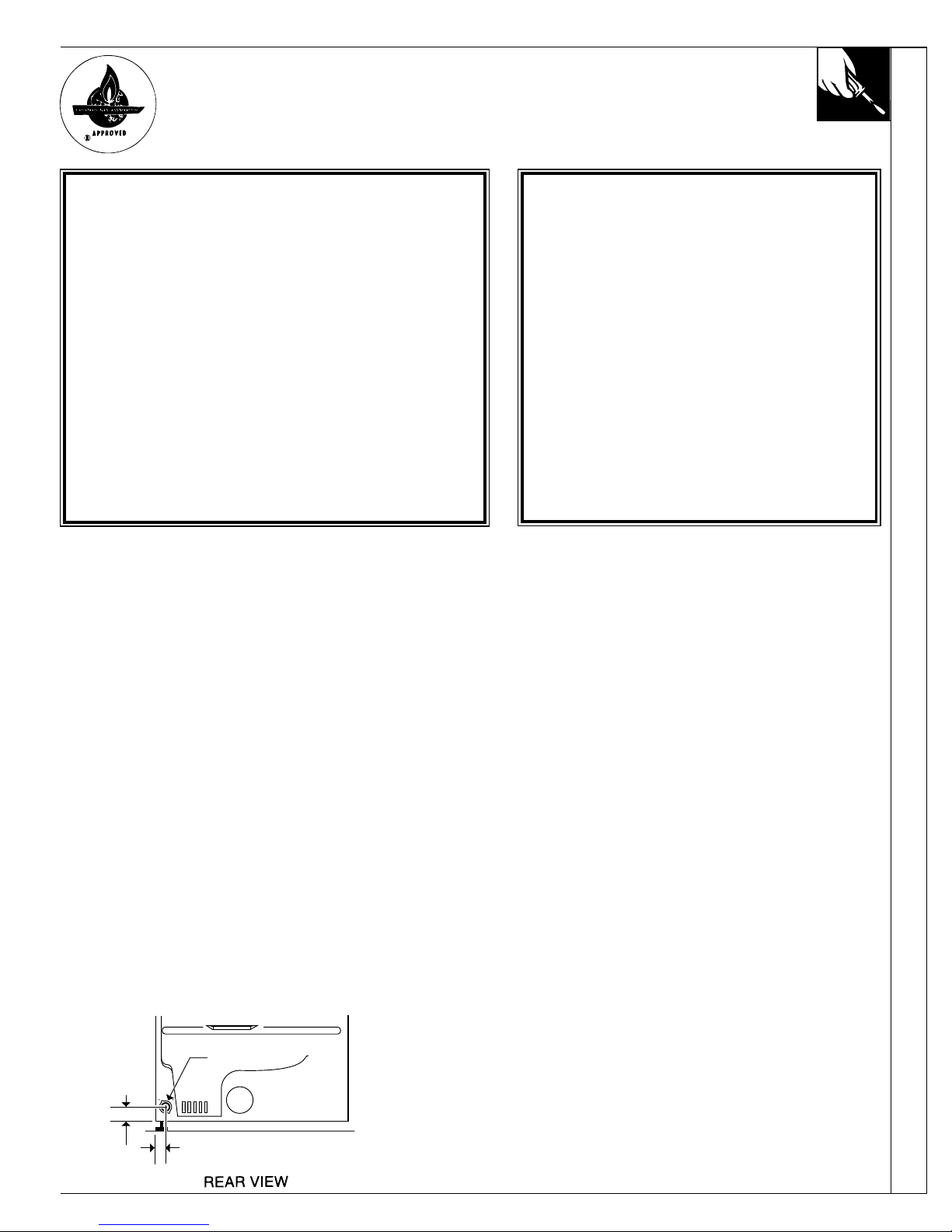
INSTALLATION – GAS DRYER
IMPORTANT - OBSERVE ALLGOVERNING CODES
Dryer must be levelled and rest firmly on the floor.
Dryer must be exhausted to the outdoors.
51mm
(2")
66 mm
(2 5/8")
MALE THREAD GAS SUPPLY
9.52 mm (3/8")
FOR YOUR SAFETY
What to do if you smell gas
• Do not try to light appliance.
• Do not touch any electrical switch ; do not use
any phone in your building.
• Clear the room, building or area of all occupants.
• Immediately call your gas supplier from a
neighbor’s phone. Follow the gas supplier’s
instructions.
• If you can not reach your gas supplier, call fire
department.
• Installation and service must be performed by
a qualified installer, service agency, or the gas
supplier.
FOR YOUR SAFETY
Do not store or use gasoline or
other flammable vapors and
liquids in the vicinity of this or
any other appliance.
GAS CONNECTION INFORMATION
Installation must conform with local Gas Codes and
with CAN/CGA-B149, Natural Gas Installation Code.
Some local codes restrict installation of gas appliances
in garages. They must be 45 cm (18”) off the ground
and protected by a barrier from vehicules.
GAS BURNER ORIFICE
This gas dryer is equipped with a Valve & Burner
Assembly for use ONLY WITH ONE TYPE OF GAS.
Using the appropriate kit, your local service
organization can convert this dryer for use with the
alternate fuel.
Use kit WE25M 35 to convert from Natural Gas to LP
Gases (Propane).
Use kit WE25M 36 to convert from LPGases to Natural
Gas.
WARNING: CONVERSION SHALL BE CARRIED
OUT IN ACCORDANCE WITH THE
REQUIREM ENTS OF THE PROVINCIAL
AUTHORITIES HAVING JURISDICTION AND/OR
ACCORDANCE WITH THE REQUIREM ENTS OF
THE CAN/CGA B149.1 AND B149.2
INSTALLATION CODE.
GAS SUPPLY
• Supply line is to be 12.7 mm (1/2 in) rigid pipe.
(9.53 mm (3/8 in) copper tubing may be used if the dryer is
operated on propane gas) and equipped with an accessible
shutoff within 6 feet (2 m) from, and in the same room with
the dryer. Increase pipe size for runs longer than 20 feet (7 m).
• During pressure test:
– When test pressure is in excess of 1/2 PSIG (3.45kPa),
disconnect dryer and its individual shutoff valve from gas
supply line prior to test.
– When test pressure is equal to or less than 1/2 PSIG
(3.45kPa), close the dryer shutoff valve prior to test.
• A 3.18 mm (1/8 in) National Pipe Taper thread plugged
tapping, accessible for test gauge connection, must be
installed immediately upstream of the gas supply connection
to the dryer. Contact your local gas utility should you have
questions on the installation of the plugged tapping.
• Pipe dope must be resistant to propane and applied sparingly
to all male threads.
• You must use with this dryer a listed gas connector in
comp liance with A N S I Z 2 1 .2 4 / C S A 6 .1 0 .
NOTE: The connector and fittings are designed for use
only on the original installation and are not to be reused for
another appliance or at another location.
CAUTION: Do not connect flexible connector nuts
directly to pipe threads. This connector must always be
installed with appropriate,and approved adapters (flare - NPT).
Keep flare end of adaptor free of grease, oil and thread sealant.
LEAK TEST
Check all connections for leaks with soapy solution or
equivalent. Leak test solutions must not contain ammonia
which could cause damage to brass fittings or pipe.
CAUTION: NEVER USE AN OPEN FLAME TO TEST
FOR GAS LEAKS.
1
3
2
4
1
3
4
2
5
10
OPERATING YOUR DRYER
W ARNING – To r e d u c e th e r is k o f f ir e , e le c tr ic s h o c k , o r in ju r y to p e r s o n s
w h e n u sin g y o u r a p p lia n c e r e a d th e IM PORTANT S AF ETY INS TRUC TIONS
b e fo re o p e r a tin g th is a p p lia n c e .
F e a tu re s a n d a p p e a ra n c e s m a y v a ry .
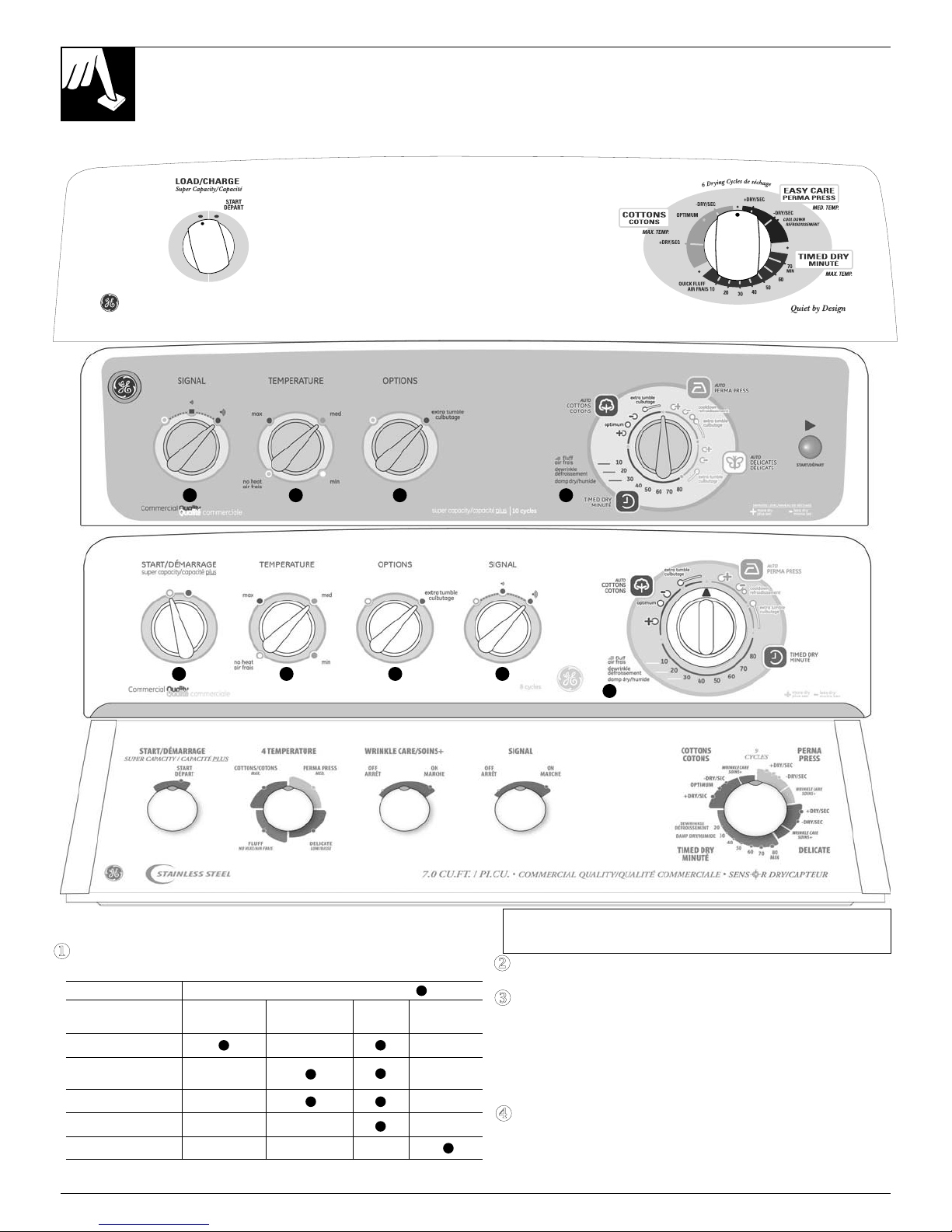
D ry in g S e le ctio n s. S e le c t th e p ro p e r h e a t o n th e F ab ric C a re se le cto r fo r y o u r
lo a d .
N O T E : D r y in g tim e s w ill v ary a c c o rd in g to th e ty p e o f h e a t u se d (E le c tric ,
N a tu ra l g a s o r L P g a s ), s iz e o f lo a d , ty p e s o f fa b ric s, w e tn ess o f c lo th e s, a n d
c o n d itio n o f e x h a u st d u cts.
C y c le S e le c to r. T u rn th e C y c le S e lec to r to th e d e sir e d c y c le settin g . T h e se le cto r
m a y b e tu rn e d in eith er d ire c tio n . S ele c t “ O p tim u m ” fo r p refe rre d e n e rg y se ttin g .
E x tr a C a re C y c le . (A v a ila b le o n so m e m o d e ls .)
T h e E x tr a C a re c y c le o p e ra te s o n ly w ith th e A u to m a tic cy cle s . T u r n th e E x tr a
C a re k n o b to S E T , a n d tu rn th e C y c le S e le c to r D ia l to th e d e sire d a m o u n t o f
h e ate d d ry in g tim e .
T o m in im iz e th e w r in k le s e ttin g in c lo th e s, th e E x tr a C a re c y c le p ro v id es fro m 15
to 20 m in u te s o f n o -h e at tu m b lin g a fte r th e c lo th es a re d ry .
U se th e E n d C y c le S ig n a l to re m in d y o u to re m o v e th e d rie d la u n d ry .
E n d C y c le S ig n a l. (A v a ila b le o n so m e m o d e ls.)
S e t E n d C y c le S ig n a l, if d e sire d . T h is s ig n a l o p e ra te s w ith a n y cy cle o n so m e
m o d e ls . T h e c o n tro l c a n b e s e t O N a n d O F F o r a n y w h e re b etw e e n O F F a n d
L O U D , d e p e n d in g o n th e m o d e l a n d d esir e d so u n d le v e l. T h e s ig n a l w ill s ta rt to
s o u n d ju s t b e fo re th e e n d o f th e c y c le to re m in d y o u to re m o v e th e c lo th es . T o sto p
th e sig n a l w h ile so u n d in g , tu rn th e sig n a l c o n tro l to O F F .
D ry in g A u to m a tic A u to m a tic
S e lec tio n s C o tto n s P e rm . P re ss T im e d U ltra C a re
(o r E a sy C a re )
C o tto n s
R e g u la r H e at
P e rm . P re ss
(o r E a sy C a re )
M e d iu m H e a t
K n its/D elica te s
L o w H e a t
F lu ff
N o H e at*
U ltra C a re
G e n tle H e a t
X
Y
Z
[
Wipe off any spills or washing
compounds. Wipe or dust with a
damp cloth. Try not to strike the
surface with sharp objects.
Dryer control panel and finishes
may be damaged by some laundry
pre-treatment soil and stain
remover products if such products
are sprayed on or have direct
contact with the dryer.
Apply these pre-treatment products
away from the dryer. The fabric
may then be washed and dried
normally. Damage to your dryer
caused by pre-treatment products is
not covered by your warranty.
Operating Instructions/Care and Cleaning
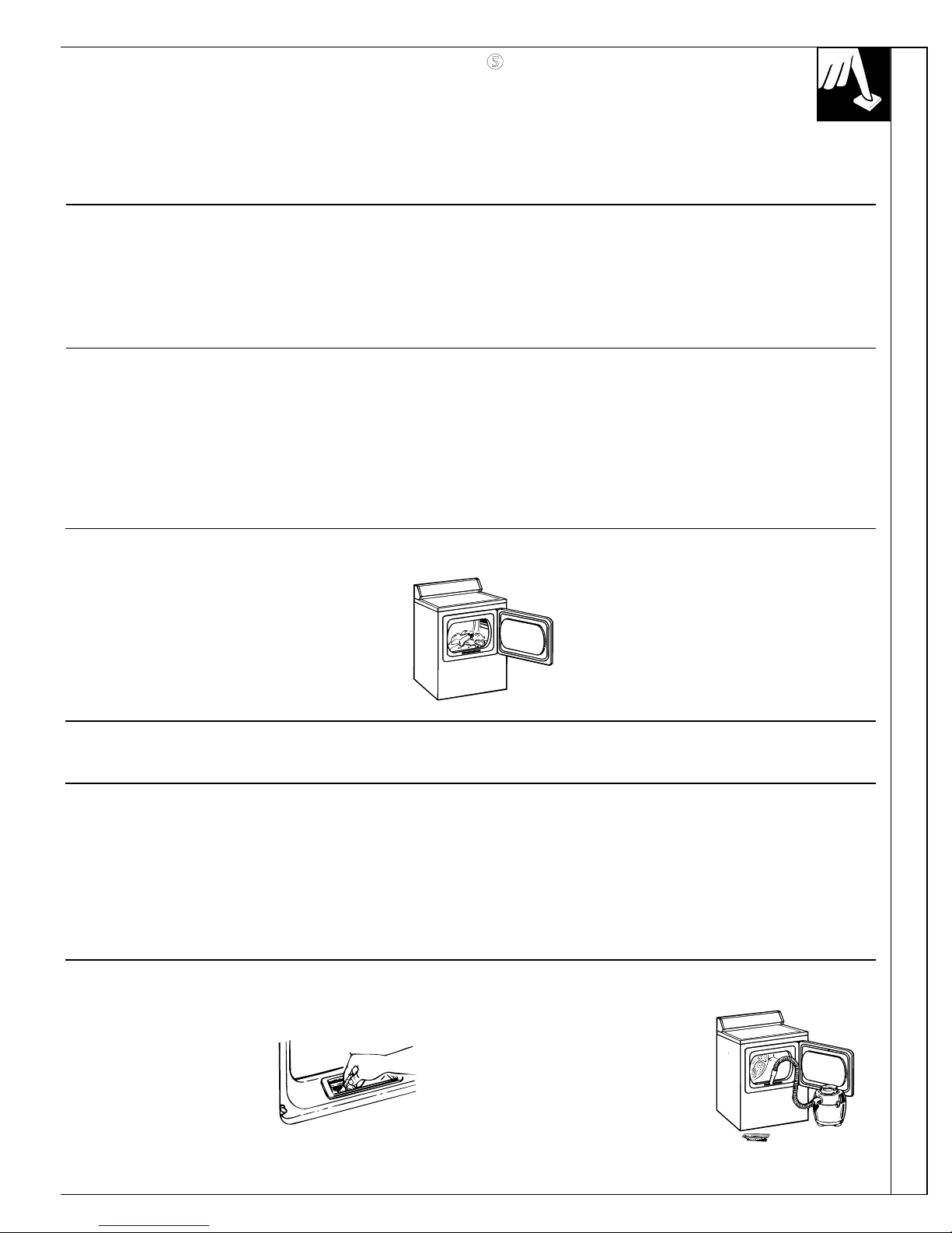
To keep your dryer
operating at peak
performance.
periodically, remove
the lint filter and
insert the suction hose
from your vacuum
cleaner into the
opening.
Polyester K nits & Perm anent Press Drying Tips
• DO NOT OV ERLOADGarments being dried or
dewrinkled should tumble
freely.
• REMOV E CLOTHES
PROMPTLY To help prevent wrinkling,
remove clothes from the dryer
promptly at the end of the
drying cycles.
• PLACE ON HANGERSPermanent press and polyester
knit garments look best if
placed on hangers after drying.
OPERATING YOUR DRYER
H OW TO L OAD TH E CL OTH ES
CARE AND CL EANING
CARE AND CL EANING
Don’t overload your dryer. Crowded
loads don’t dry efficiently and clothes
may be unnecessarily wrinkled. Loads
should look like this:
H OW TO SORT CL OTH ES
As a general rule, sort clothes by surface texture, fabric, colour and weight, as you would for your washer.
Dryer Ex terior
L int filter
B efore every
dryer use, clean the
lint filter. Put your
moistened fingers at
one side of the filter
and wipe in a sideways
motion all the way
across to the other side.
11
This signal should always be used when drying
polyester knits or permanent press items which should
be removed as soon as the dryer stops to help prevent
setting of wrinkles.
If the signal is on and you choose the Extra Care
Cycle, you will hear the signal sound on and off
throughout the cycle. This reminds you that the
clothes are dry.
Start. Turn the Start knob to start the dryer.
(Opening the door during operation stops the
dryer. To restart, close the door and follow
above directions.)
COL OR L OGIC (Av ailable on som e m odels)
Select the correct FAB RIC CARE setting. Match the
particular color below the words with the same color on the
Cycle Dial.
Example: Drying a load of clothing labeled permanent press.
1. Choose the FAB RIC CARE setting - for this load it
would be the EASY CARE MED HEAT (which is a
particular color).
2. Turn the Cycle Dial to the area that has the same color as
the FAB RIC CARE setting you have chosen - for this
load it would be the EASY CARE PERM PRESS.
\
 Loading...