

GE PVB94DT1BB, PVB94DT2BB, PVB94DT3BB, PVB94DT4BB, PVB94DT5BB Installation Guide
...
Installation
Instructions
Downdraft Vent Systems
PVB94
PVB98
ZVB30
ZVB36
Safet Information
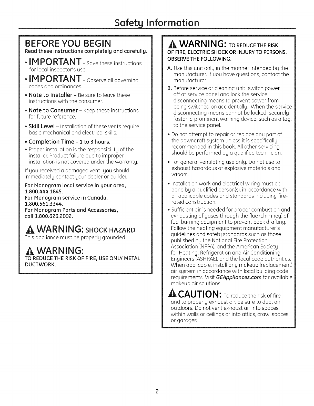
BEFORE YOU BEGIN
Read these instructions completelg and carefullg.
"IMPORTANT- Savetheseinstructions
for local inspector's use.
"IM PORTANT- Observeallgoverning
codes and ordinances.
, Note to Installer- Be sureto leavethese
instructionswiththe consumer.
, Note to Consumer - Keep these instructions
for future reference.
, Skill Level- Installation of these vents require
basic mechanical and electrical skills.
, Completion Time- 1to 3 hours.
. Proper installation is the responsibility of the
installer. Product failure due to improper
installation is not covered under the warranty.
If you received a damaged vent, you should
immediately contact your dealer or builder.
For Monogram local service in gour area,
1.800.444.1845.
For Monogram service in Canada,
1.800.561.3344.
For Monogram Parts and Accessories,
call 1.800.626.2002.
--_WARNING: SHOCKHAZARD
Thisappliancemust be properlygrounded.
A WARNING:
TO REDUCE THE RISK OF FIRE,USE ONLY METAL
DUCTWORK.
A WA RNING:TOREDUCETHERISK
OF FIRE,ELECTRIC SHOCK OR INJURY TO PERSONS,
OBSERVE THE FOLLOWING.
A. Use this unit only in the manner intended by the
manufacturer. If you have questions, contact the
manufacturer.
BoBefore service or cleaning unit, switch power
off at service panel and lock the service
disconnecting means to prevent power from
being switched on accidentally. When the service
disconnecting means cannot be locked, securely
fasten a prominent warning device, such as a tag,
to the service panel.
Do not attempt to repair or replace any part of
the downdraft system unless it is specifically
recommended in this book. All other servicing
should be performed by a qualified technician.
. For general ventilating use only. Do not use to
exhaust hazardous or explosive materials and
vapors.
Installation work and electrical wiring must be
done by a qualified person(s), in accordance with
all applicable codes and standards including fire-
rated construction.
• Sufficient air is needed for proper combustion and
exhausting of gases through the flue (chimney) of
fuel burning equipment to prevent back drafting.
Follow the heating equipment manufacturer's
guidelines and safety standards such as those
published by the National Fire Protection
Association (NFPA),and the American Societg
for Heating, Refrigeration and Air Conditioning
Engineers (ASHRAE), and the local code authorities.
When applicable, install ang makeup (replacement)
air system in accordance with local building code
requirements. Visit GEApplionces.com for available
makeup air solutions.
ACAUTION: To reduce the risk of fire
and to properly exhaust air, be sure to duct air
outdoors. Do not vent exhaust air into spaces
within walls or ceilings or into attics, crawl spaces
or garages.
CONTENTS
Design Information
Product Dimensions ................................................................3
Accessories ..................................................................................3
Advance Planning ...............................................................4, 5
Installation Preparation
Clearances ..............................................................................6, 7
Parts Supplied ............................................................................7
Tools and Materials Required .............................................7
Remove Packaging ..................................................................7
Power Supplg .............................................................................8
Venting Options .........................................................................9
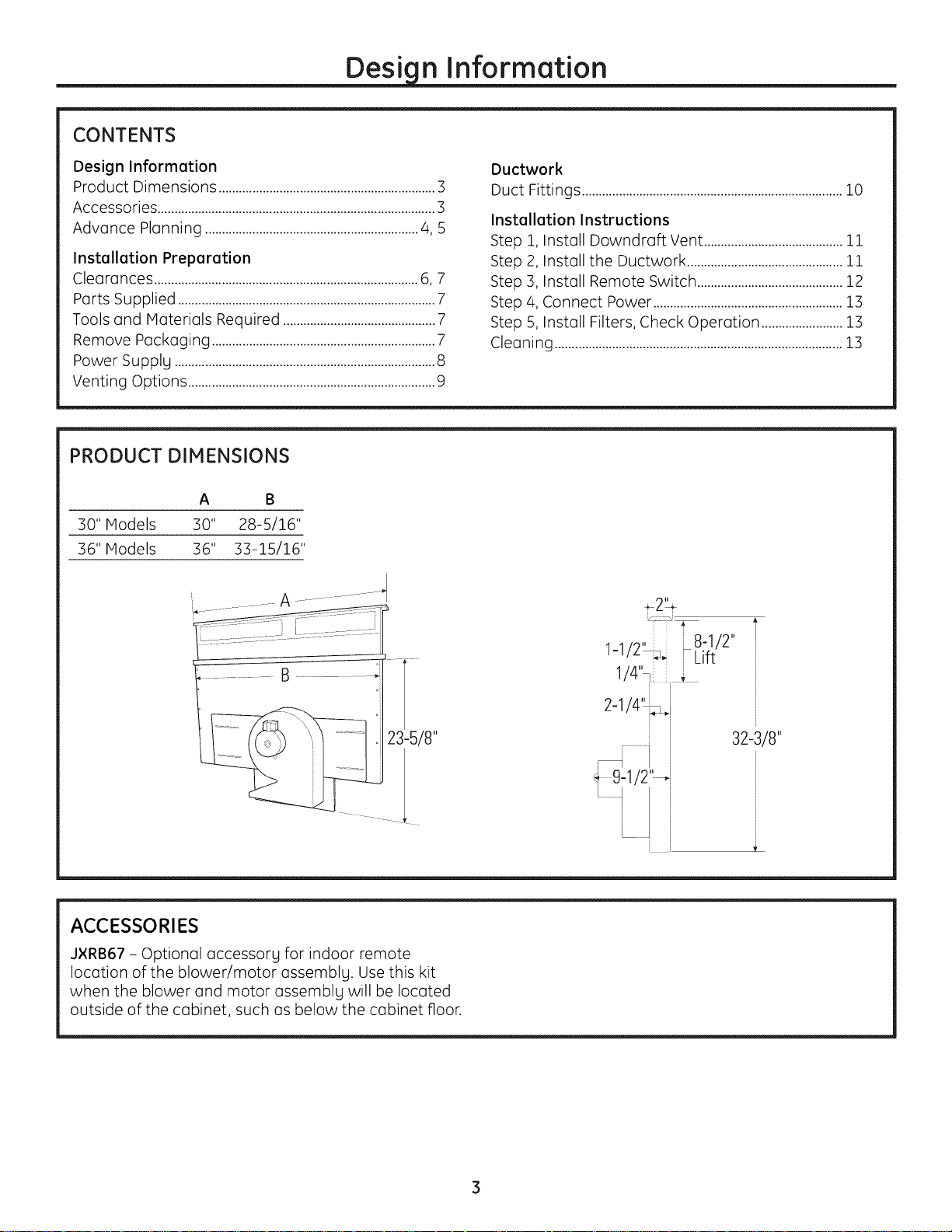
PRODUCT DIMENSIONS
A
30" Models 30"
36" Models 36"
Ductwork
Duct Fittings .............................................................................10
Installation Instructions
Step 1, Install Downdraft Vent .........................................11
Step 2, Install the Ductwork ..............................................11
Step 3, Install Remote Switch ...........................................12
Step 4, Connect Power ........................................................13
Step 5, Install Filters, Check Operation ........................13
Cleaning .....................................................................................13
23-5/8"
ACCESSORIES
J×RB67 - Optional accessorg for indoor remote
location of the blower/motor assemblg. Use this kit
when the blower and motor assemblg will be located
outside of the cabinet, such as below the cabinet floor.
; i
1-1 - 2
I/4_
,i7
2-1/4_j
_ 32-3/8"
Desi n Information
ADVANCE PLANNING
Downdraft Vent and Cooktop Cutout
The installation of these downdraft vents with ang GE
or Monogram cooktop requires careful consideration.
Before you begin, review the combination cutout
illustrations on page 6.
Countertop Requirements
The countertop must have a deep flat surface to
accommodate the cooktop and the vent. Countertops
with a rolled front edge and backsplash may not provide
the flat surface area required.
Base Cabinet Requirements
Review the installation preparation on Page 6 to ensure
the base cabinet is deep enough to accommodate the
minimum clearance and that the side and back wall
locations allow the vent to be properlg secured. Ensure
no internal structure elements (such as cabinet corner
braces) interfere with the vent or cooktop.
Before gou begin, gou must:
1. Review countertop dimension illustrations to be
sure gou will have enough flat countertop surface.
2. Check to be sure that the total countertop depth
required (including minimum cutout to front edge
depth) allows enough space for a backsplash.
3. Review the cabinet illustration. Check to be sure
the interior cabinet depth will house the cooktop
burner box, the vent and the cutout clearance from
the front.
4. When countertop and cabinet depth present a
problem, review Creative Solutions.
5. Read this book completelg to accuratelg plan the
installation location, clearances and ductwork
requirements.
With careful planning, gou can achieve acustom look
with minimal adjustments.
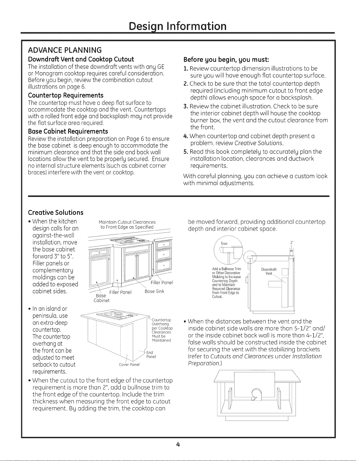
Creative Solutions
. When the kitchen
design calls for an
Maintain Cutout Clearances
to Front Edge as Specified
against-the-watt
installation, move
the base cabinet _!_i
forward 3" to 5".
Filler panels or
complementarg
moldings can be
added to exposed
cabinet sides. ' Filler Panel
Base
Cabinet
\
Filler Panel
Base Sink
. In an island or
peninsula, use
an extra-deep
countertop.
The countertop
Overhang
per Cooktop
Clearances
Must be
Maintained
overhang at
the front can be
adjusted to meet
setback to cutout
CoverPanel
-nd
Panel
requirements.
. When the cutout to the front edge of the countertop
requirement is more than 2", add a bullnose trim to
the front edge of the countertop, include the trim
thickness when measuring the front edge to cutout
requirement. Bg adding the trim, the cooktop can
be moved forward, providing additional countertop
depth and interior cabinet space.
Add a BullnoseTrim
orOtherDecorative
Moldingto Increase
CountertopDepth i
andto Maintain
RequiredClearance
FromFrontEdgeto
Cutout.
. When the distances between the vent and the
inside cabinet side walls are more than 5-1/2" and/
or the inside cabinet back wall is more than 4-1/2",
false walls should be constructed inside the cabinet
for securing the vent with the stabilizing brackets
(refer to Cutouts and Clearances under Installation
Preparation.)
I I
4

Desi n Information
Clearances
, The downdraft system with blower, motor and
ductwork will occupy the cabinet below the
countertop and cooktop.
• The blower/motor assembly can be located
below the cabinet floor. The assembly will fit
between 16" floor joists. Order JXRB67 for indoor
remote locations.
Refer to your specific cooktop installation
instruction for appropriate clearances.
, Installation must conform with local codes.
Ductwork
Prepare ductwork to vent to the outdoors.
, Use the shortest and straightest duct run possible.
, The maximum permissible equivalent length for
duct run is 100 feet.
• Refer to "Duct Fittings" chart to calculate
equivalent length for various duct configurations.
o The downdraft blower system is designed to use
3-1/4" x 10" ductwork. It can be transitioned to 6"
round.
, Ductwork MUST be vented to the outside-never
into a crawl space, attic or other enclosed space.
, Determine the need for a wall cap or roof cap.
Order the cap in advance.
• When applicable, install any makeup (replacement)
air system in accordance with local building
code requirements. Visit GEAppliances.com for
available makeup air solutions.
Electricaland Gas Locations
Plan the placement of the electrical outlet and gas
connections (if used) carefully. Electrical outlets and
gas connections cannot be placed on the back wall
of the cabinet because it may interfere with the
downdraft plenum. Refer to POWER SUPPLYsection
for information on location of electrical and gas
connections.
, Install a standard electrical outlet on the right side
of the cabinet within reach of the vent's two-foot-
long power cord.
o The vent and a GE or Monogram gas cooktop
combination can operate from the same 120-volt
standard duplex outlet.
, Electric cooktops must operate from a separate
240-volt junction box.
• A 90 ° elbow (not supplied) can be installed onto
the inlet of the gas cooktop and route the gas
connections to avoid interference when installed
with a downdraft vent or other cabinetry features.
, The hood must vent down or to the left when
installed with a GE or Monogram gas cooktop to
avoid interference with the inlet of the gas cook-
top.
 Loading...