

GE PVB94DT Specification
PVB94DT
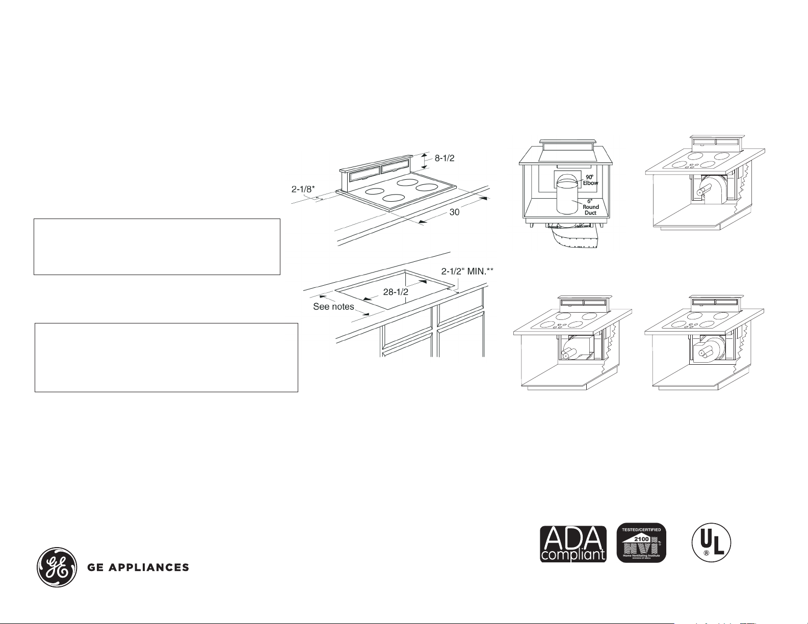
GE Profile™ Series 30" Telescopic Downdraft System
DimensiOns anD installatiOn inFOrmatiOn (in inches)
nOte: Telescopic downdraft vents are not recommended
to be installed with cooktops that are flush mounted.
Approved for use with the following GE Profile™and GE®
Series cooktops–30" electric models, 30" gas sealed
burner models and 30" induction models.
nOt apprOVeD FOr use with stanDarD
burner gas cOOktOps.
nOte: The cooktop must be at least 26" deep with
a flat surface area of 23-1/2" or more, front to back.
In addition, other clearances to the front edge of the
countertop must be considered.
nOte: Dimensions shown are for reference only.
Before cutting out countertop, refer to instructions
packed with downdraft and cooktop.
nOte: Installation on cabinets/countertops against
the wall will not be possible in most applications.
Against the wall installations are limited to dimension
requirements. Refer to installation instructions packed
with product for further details.
Venting OptiOns (in inches)
thrOugh the FlOOr
in cabinet Discharg e
(right)
in cabinet Discharg e
(DOwn)
in cabinet Discharg e
(leFt)
JXrb67 inDOOr remOte accessOry. Optional
accessory may be ordered for installation of motor and
blower assembly in an indoor remote location.
For answers to your Monogram, GE Profile™ Series
or GE® Series appliance questions, visit our website
at geappliances.com or call GE Answer Center®
service, 800.626.2000.
Listed by
Underwriters
Laboratories
Speci fication Revised 10/15
PVB94DT
6" ROUND
STRAIGHT
3-1/4" X 10"
TO 6" ROUND
6" ROUND
STRAIGHT
3-1/4" X 10"
TO 6" ROUND
TRANSITION
6" ROUND
TO 3-1/4 X 10"
TRANSITIONS
6" ROUND
STRAIGHT
3-1/4" X 10"
STRAIGHT
6"
90° ELBOW
3-1/4" X 10"
TO 6" ROUND
TRANSITION
6" ROUND
TO 3-1/4 X 10"
TRANSITIONS
90° ELBOW
3-1/4" X 10"
TO 6" ROUND
TRANSITION
90° ELBOW
6" ROUND
STRAIGHT
3-1/4" X 10"
STRAIGHT
6"
90° ELBOW
6"
45° ELBOW
3-1/4" X 10"
TO 6" ROUND
TRANSITION
6" ROUND
TO 3-1/4 X 10"
TRANSITIONS
90° ELBOW
3-1/4" X 10"
TO 6" ROUND
TRANSITION
90° ELBOW
6" ROUND
WALL CAP
WITH DAMPER
6" ROUND
STRAIGHT
3-1/4" X 10"
STRAIGHT
3-1/4" X 10"
90° ELBOW
6"
90° ELBOW
6"
45° ELBOW
3-1/4" X 10"
TO 6" ROUND
TRANSITION
6" ROUND
TO 3-1/4 X 10"
TRANSITIONS
90° ELBOW
3-1/4" X 10"
WALL CAP
WITH DAMPER
3-1/4" X 10"
TO 6" ROUND
TRANSITION
90° ELBOW
6" ROUND
WALL CAP
WITH DAMPER
6" ROUND
STRAIGHT
3-1/4" X 10"
STRAIGHT
3-1/4" X 10"
90° ELBOW
3-1/4" X 10"
45° ELBOW
6"
90° ELBOW
6"
45° ELBOW
3-1/4" X 10"
TO 6" ROUND
TRANSITION
6" ROUND
TO 3-1/4 X 10"
TRANSITIONS
90° ELBOW
6" ROUND
ROOF CAP
3-1/4" X 10"
WALL CAP
WITH DAMPER
3-1/4" X 10"
TO 6" ROUND
TRANSITION
90° ELBOW
6" ROUND
WALL CAP
WITH DAMPER
6" ROUND
STRAIGHT
3-1/4" X 10"
STRAIGHT
3-1/4" X 10"
90° ELBOW
3-1/4" X 10"
45° ELBOW
3-1/4" X 10"
45° ELBOW
6"
90° ELBOW
6"
45° ELBOW
3-1/4" X 10"
TO 6" ROUND
TRANSITION
6" ROUND
TO 3-1/4 X 10"
TRANSITIONS
90° ELBOW
6" ROUND
ROOF CAP
3-1/4" X 10"
WALL CAP
WITH DAMPER
6" ROUND
ROOF VENT
3-1/4" X 10"
TO 6" ROUND
TRANSITION
90° ELBOW
6" ROUND
WALL CAP
WITH DAMPER
6" ROUND
STRAIGHT
3-1/4" X 10"
STRAIGHT
3-1/4" X 10"
90° ELBOW
3-1/4" X 10"
45° ELBOW
3-1/4" X 10"
45° ELBOW
6"
90° ELBOW
6"
45° ELBOW
3-1/4" X 10"
TO 6" ROUND
TRANSITION
6" ROUND
TO 3-1/4 X 10"
TRANSITIONS
90° ELBOW
6" ROUND
ROOF CAP
3-1/4" X 10"
WALL CAP
WITH DAMPER
6" ROUND
ROOF VENT
3-1/4" X 10"
TO 6" ROUND
TRANSITION
90° ELBOW
6" ROUND
WALL CAP
WITH DAMPER
6" ROUND
TO 3-1/4 X 10"
TRANSITIONS
3-1/4" X 10"
TO 6" ROUND
TRANSITION
6" ROUND
TO 3-1/4 X 10"
TRANSITIONS
90° ELBOW
3-1/4" X 10"
WALL CAP
WITH DAMPER
3-1/4" X 10"
TO 6" ROUND
TRANSITION
90° ELBOW
6" ROUND
WALL CAP
WITH DAMPER
3-1/4" X 10"
TO 6" ROUND
TRANSITION
6" ROUND
TO 3-1/4 X 10"
TRANSITIONS
90° ELBOW
6" ROUND
ROOF CAP
3-1/4" X 10"
WALL CAP
WITH DAMPER
3-1/4" X 10"
TO 6" ROUND
TRANSITION
90° ELBOW
6" ROUND
WALL CAP
WITH DAMPER
3-1/4" X 10"
TO 6" ROUND
TRANSITION
3-1/4" X 10"
TO 6" ROUND
TRANSITION
6" ROUND
TO 3-1/4 X 10"
TRANSITIONS
90° ELBOW
90° ELBOW
6" ROUND
TO 3-1/4 X 10"
TRANSITIONS
90° ELBOW
3-1/4" X 10"
TO 6" ROUND
TRANSITION
90
6" ROUND
TO 3-1/4 X 10"
TRANSITIONS
90° ELBOW
3-1/4" X 10"
TO 6" ROUND
TRANSITION
90° ELBOW
6" ROUND
WALL CAP
WITH DAMPER
6" ROUND
TO 3-1/4 X 10"
TRANSITIONS
90° ELBOW
3-1/4" X 10"
WALL CAP
WITH DAMPER
3-1/4" X 10"
TO 6" ROUND
TRANSITION
90° ELBOW
6" ROUND
WALL CAP
WITH DAMPER
3-1/4" X 10"
TO 6" ROUND
TRANSITION
6" ROUND
TO 3-1/4 X 10"
TRANSITIONS
90° ELBOW
3-1/4" X 10"
TO 6" ROUND
TRANSITION
90° ELBOW
3-1/4" X 10"
TO 6" ROUND
TRANSITION
6" ROUND
TO 3-1/4 X 10"
TRANSITIONS
90° ELBOW
3-1/4" X 10"
TO 6" ROUND
TRANSITION
90° ELBOW
6" ROUND
WALL CAP
WITH DAMPER
3-1/4" X 10"
TO 6" ROUND
TRANSITION
6" ROUND
TO 3-1/4 X 10"
TRANSITIONS
90° ELBOW
3-1/4" X 10"
WALL CAP
WITH DAMPER
3-1/4" X 10"
TO 6" ROUND
TRANSITION
90° ELBOW
6" ROUND
WALL CAP
WITH DAMPER
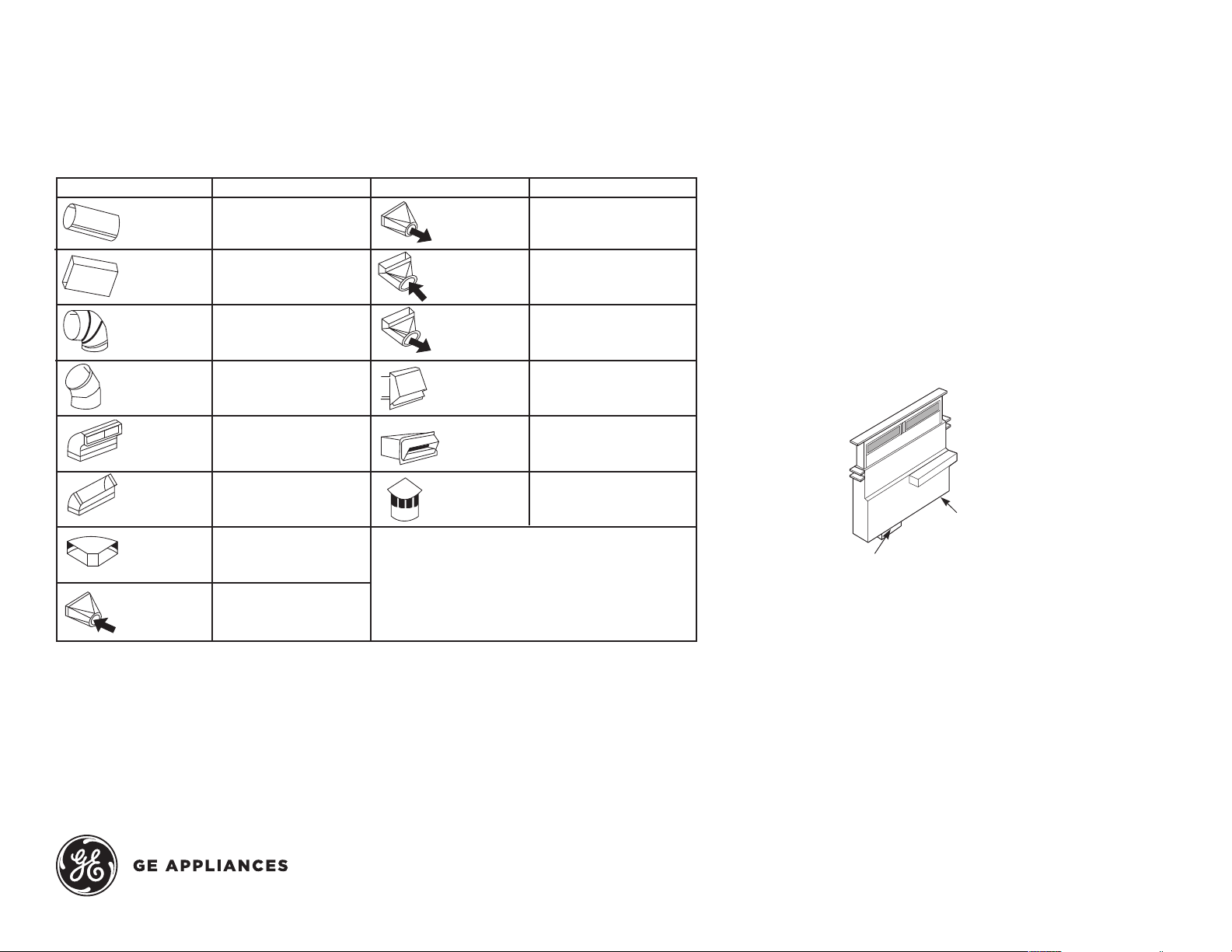
GE Profile™ Series 30" Telescopic Downdraft System
Venting Duct inFOrmatiOn
Duct pieces equiValent length* Duct pieces equiValent length*
3-1/4" X 10"
STRAIGHT
1 ft. (per foot length)
1 ft. (per foot length)
12 ft.
7 ft.
3-1/4" X 10"
TO 6" ROUND
TRANSITION
6" ROUND
TO 3-1/4 X 10"
TRANSITIONS
° ELBOW
2 ft.
4 ft.
4 ft.
24 ft.
plan the DuctwOrk
1. This downdraft blower system is designed for use with
3-1/4" x 10" ductwork (can be transitioned to 6" round). Two
different discharge directions are available with side-toside adjustment for the accurate alignment of ductwork.
2. For best performance: choose the ducting option which
allows the shortest length of ductwork and a minimum
number of elbows and transitions. Check location of floor
joists, wall joists, wall studs, electrical wiring or plumbing
for possible interference.
14 ft.
12 ft.
33 ft.
2 ft.
24 ft.
6" ROUND
ROOF CAP
33 ft.
shOulD nOt eXceeD 100 equiValent Ft.
* Equivalent length of duct pieces are based on actual
test conducted by GE Evaluation Engineering and
reflect requirements for good venting performance
with a downdraft system rated at 390 CFM
For answers to your Monogram, GE Profile™ Series
or GE® Series appliance questions, visit our website
at geappliances.com or call GE Answer Center®
service, 800.626.2000.
Right
discharge
Left discharge
(as shipped)
steps tO Determine FleXible Ducting’s
equiValent length
1. Measure the actual amount of offset (Maximum 3"
recommended). The effect upon airflow is dependent upon
the amount of offset.
2. Calculate the equivalent ducting allowances using:
(__in. offset) x (14 ft. per inch) = __ft. equivalent length.
3. Ensure that the total equivalent length of ducting does not
exceed the maximum recommendation of 100 feet.
Speci fication Revised 10/15
 Loading...