How it Works
Log In / Sign Up
Buy Points
How it Works
FAQ
Contact Us
Questions and Suggestions
Users
GE
Loading...
P
PTS9000
PTS9000BN
PTS9000BNTS
PTS9000SN
PTS9000SNSS
PTS9200
PTS9200SNSS
3
PTU427SAMR
PTU463SAMR
2
PTU527SAMR
2
PTU565SAMR
2
PTV15SAMR
PTV16SAMR
2
PTV19SAMR
2
PTV20SAMR
2
PTV440SAMR
PTV470SAMR
PTV530SAMR
PTV570SAMR
PTW600
PTW605
PTW9000
PTW9000SNSS
2
PTWN6050M
PTWN6050M0WT
2
PTWN6050MWT
2
PTWN6250M
PTWN6250M0WT
3
PTWN6250MWT
2
PTWN8050M
PTWN8050M0WW
PTWN8050MWW
2
PTWN8055M
PTWN8055M0MS
PTWN8055MMS
PTZ 100
PTZ 12X
PTZ 140
PTZ 70
Pump Motors
5
PV411A
PV970
3
PV970N1SS
PV970N2SS
PV970NSS
3
PV976
3
PV976N
PV976N1SS
PV976N2SS
PV976NSS
3
PV977
2
PV977N1SS
PV977N2SS
PV977NSS
2
PVB37
2
PVB67
2
PVB94
9
PVB94DT
PVB94DT1BB
2
PVB94DT2BB
2
PVB94DT3BB
2
PVB94DT4BB
2
PVB94DT5BB
4
PVB94DTBB
7
PVB94SN
PVB94SNSS
PVB94ST1SS
2
PVB94ST2SS
2
PVB94ST3SS
2
PVB94ST4SS
2
PVB94ST5SS
3
PVB94STSS
11
PVB98
10
PVB98DT
PVB98DT1BB
2
PVB98DT2BB
2
PVB98DT3BB
2
PVB98DT4BB
2
PVB98DT5BB
4
PVB98DTBB
9
PVB98SN
PVB98SNSS
PVB98ST
PVB98ST1SS
2
PVB98ST2SS
2
PVB98ST3SS
2
PVB98ST4SS
2
PVB98ST5SS
4
PVB98STSS
6
PVD
PVD28BYNBFS
PVD28BYNFS
3
PVH1970
PVIG940
3
PVM1790
4
PVM1790DR
PVM1790DR1BB
2
PVM1790DR1CC
2
PVM1790DR1WW
2
PVM1790DRBB
2
Loading...
Loading...
Nothing found
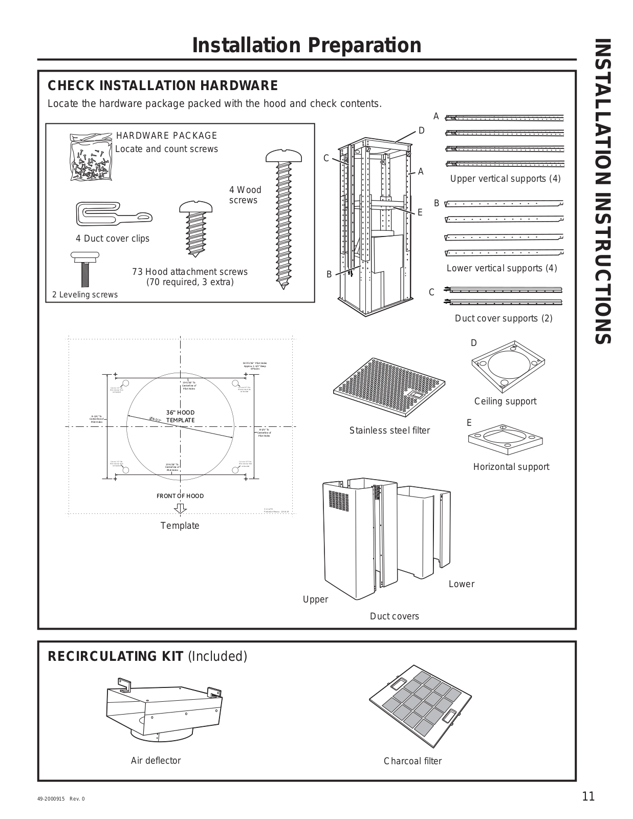
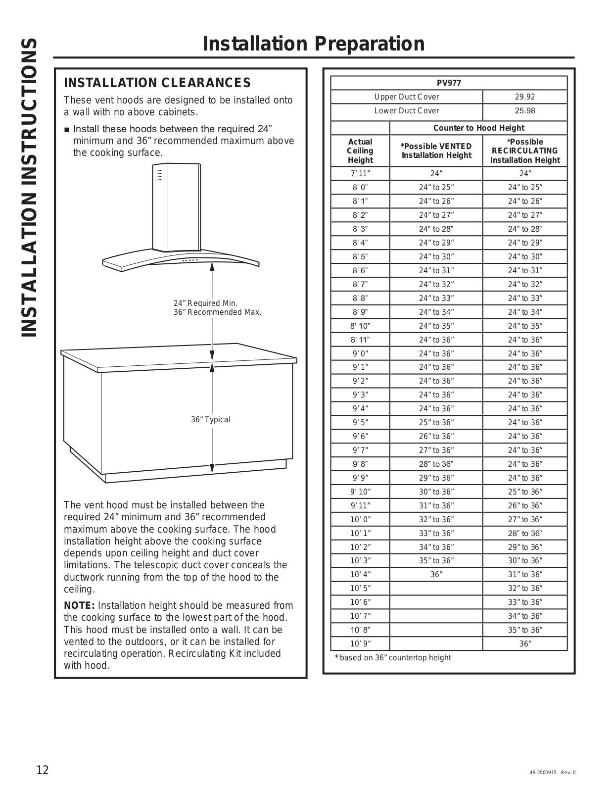
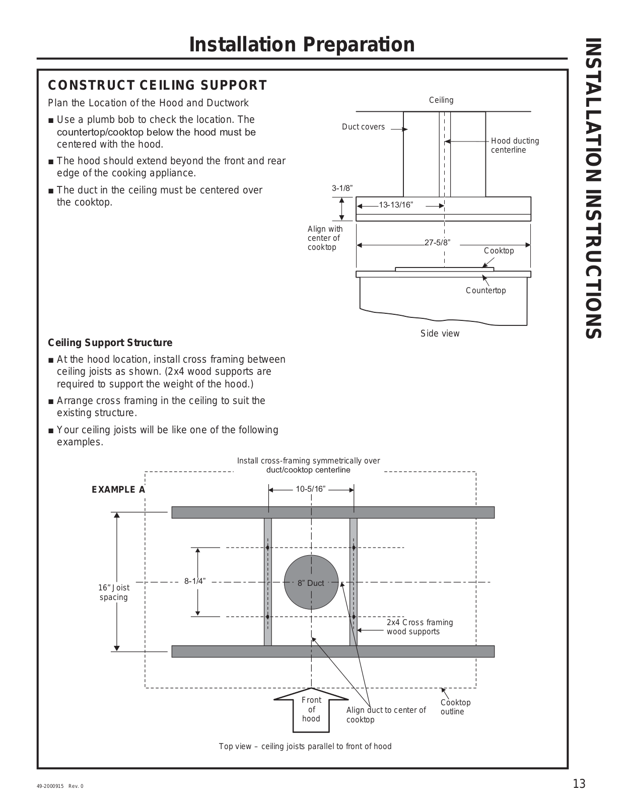
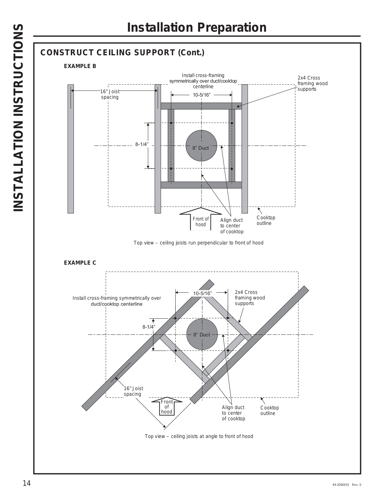
PV977
Owner's Manual And Installation Instructions
60 pgs
1.27 Mb
0
Owner’s Manual & Installation Instructions
48 pgs
2.3 Mb
0
Table of contents
Loading...
GE PV977 Owner’s Manual & Installation Instructions
...
GE Owner’s Manual & Installation Instructions
Download
Specifications and Main Features
Frequently Asked Questions
User Manual
Download
Loading...
+
hidden pages
Unhide
You need points to download manuals.
1 point = 1 manual.
You can buy points or you can get point for every manual you upload.
Buy points
Upload your manuals